
 Open Access Article
 This Open Access Article is licensed under a Creative Commons Attribution-Non Commercial 3.0 Unported Licence
ZIF-8 thin films by a vapor-phase process: limits to growth†
Virginie
Perrot
ab,
Arthur
Roussey
c,
Anass
Benayad
c,
Marc
Veillerot
a,
Denis
Mariolle
a,
Albert
Solé-Daura‡
d,
Caroline
Mellot-Draznieks
 d,
Florence
Ricoul
a,
Jérôme
Canivet
b,
Elsje Alessandra
Quadrelli
*b and
Vincent
Jousseaume
*a
d,
Florence
Ricoul
a,
Jérôme
Canivet
b,
Elsje Alessandra
Quadrelli
*b and
Vincent
Jousseaume
*a
aUniv. Grenoble Alpes, CEA, LETI, F-38000 Grenoble, France. E-mail: vincent.jousseaume@cea.fr
bUniversity of Lyon, Institut de Chimie de Lyon, IRCELYON UMR 5256–CNRS–Université Lyon 1, Institut de recherche sur la catalyse et l'environnement, Villeurbanne, France. E-mail: elsje.quadrelli@ircelyon.univ-lyon1.fr
cUniv. Grenoble Alpes, CEA, LITEN, F-38000 Grenoble, France
dLaboratoire de Chimie des Processus Biologiques, UMR CNRS 8229, Collège de France, Sorbonne Université, PSL Research University, 11 Place Marcelin Berthelot, 75231 Paris Cedex 05, France
First published on 31st March 2023
Abstract
Metal–organic frameworks are a class of porous materials that show promising properties in the field of microelectronics. To reach industrial use of these materials, gas phase techniques are often preferred and were recently introduced. However, the thicknesses achieved are not sufficient, limiting further development. In this work, an improved gas phase process allowing ZIF-8 layer formation of several hundreds of nm using cyclic ligand/water exposures is described. Then, by a combination of in-depth surface analyses and molecular dynamics simulations, the presence and role of hydroxyl defects in the ZIF-8 layer to reach this thickness are established. At the same time, this study unveils an inherent limit of the method: thickness growth is consubstantial with defect repairing upon the crystallites ripening; such defect repairing eventually leads to the decrease of the pore window below the diffusion radius of the incoming linker, thus apparently capping the maximum MOF thickness observable for this type of material topology through this growth method.
Introduction
Nanoporous hybrid organic–inorganic thin films present many distinctive properties with respect to the different materials introduced these last years for the fabrication of electronic devices, filling a large gap between fully inorganic and organic materials.1–3 For instance, porous organosilicates (SiOCH) are now industrialized as low dielectric constant insulators in integrated-circuit interconnections4 and nanoporous SiOCH thin films are used for the microfabrication of commercial integrated gas sensors based on nano-electro-mechanical systems.5 Today, one of the challenges is to extend the number and the type of porous organic–inorganic hybrids that can be deposited and integrated using processes compatible with the microelectronic industry in order to improve the current applications and to develop new ones. Vacuum-based techniques for the material deposition are often crucial in this context, since they can ensure uniform and reproducible deposition of thin films (typically a few tens to a few hundreds of nanometers) on large surfaces.Metal–Organic Frameworks (MOFs), crystalline materials made of inorganic nodes (metal ions or clusters) linked together by organic ligands with covalent bonds, are among the challenging phases for which an appropriate deposition method for these types of applications is not yet developed. MOFs are of potential interest since they have demonstrated great capabilities in many applications such as gas capture,6,7 gas separation8,9 and catalysis;10–12 they also show great potential as sensitive layers for sensors13–15 or insulators in microelectronic devices.1,16 A precursor in the field of MOFs for micro-processing-compatible applications is the ZIF-817 for which a seminal work reports its growth as thin-film by gas-phase only process,18 and which has been applied on various substrates for the preparation of gas sensors,19 membranes20–22 and supermicrocapacitors.23,24
However, the gas-phase only process, based on the exposure of ZnO thin film to the ligand 2-methyl-imidazole atmosphere, can fully convert only thin oxide layers (<15 nm).25 Generally, a residual oxide is observed underneath MOF films formed from thicker oxide layers. A similar maximum value of 10 nm of converted oxide from large ZnO nanoparticles was also reported in mechanochemistry.26 Addition of water vapor during the conversion facilitates the growth of ZIF-8 and is shown to increase the reaction rate and the final thickness, but at the expense of the surface roughness27 and with thickness remaining around 100 nm, that is below the practical threshold for most sensing applications.
In this work, a new process based on repeated exposure to the 2-methylimidazole (MeIm-H) ligand and water vapor, which allows to produce films with controllable thicknesses up to a few hundred nanometers, is reported. ZIF-8 formation is demonstrated by infrared spectroscopy, in-plane X-ray diffraction and X-ray photoelectron spectroscopy. The porosity of the layer is confirmed by ellipsometric porosimetry. Insight into the mechanism at molecular level is brought through XPS and ToF-SIMS depth profiles. With the help of atomistic molecular dynamics simulations, the importance of the presence and the role of hydroxyl defects within the ZIF-8 layer and in the ZnO are discussed, and an inherent limit on the process final layer thickness is uncovered.
Experimental
Synthesis of ZIF-8 films
First, 50 nm thick ZnO films were grown on Si wafer by atomic layer deposition (ALD) using a commercial Savannah reactor (Cambridge Nanotech). The deposition occurred at 150 °C with diethylzinc (DEZ) as the Zn-source and water as the oxidizing precursors (25 ms pulse times and 25 s purge times; 0.13 mbar reactor pressure). A home-made reactor was used for conversion of ZnO layers into ZIF-8. The reactor was composed of a heated reaction chamber (115 °C) with two samples holders (∼1.5 cm2) and connected to a pump. 1 g of 2-methylimidazole (MeIm-H) powder (99%, purchased from Sigma-Aldrich, and dried under vacuum), and around 0.5 mL of deionized water were placed and heated in separated containers, respectively at 140 °C and 100 °C. To induce ZnO conversion, vaporized MeIm-H is introduced in the closed chamber containing the ZnO samples, followed by water (PH2O = 400 mbar). After 5 minutes, the reactor was put under vacuum. The linker/water exposures were repeated up to 20 times. In the following, samples are denoted ZIF-8@N_exposures, with N the number of linker/water exposure.Activation procedure of ZIF-8 films
Physical and chemical characterizations were done before or after an activation step. Therefore, “as deposited” means without activation step and “activated” means after activation. In all cases, the ZIF-8 films once produced and once activated were stored under nitrogen. For activation, the ZIF-8 thin films were thermally treated in an oven from room temperature to 280 °C (ramp ∼5° min−1) under a nitrogen flow and kept at 280 °C for few minutes.In-plane X-ray diffraction
In-plane X-ray diffraction analysis (XRD) were performed on a Rigaku, SmartLab diffractometer equipped with Cu Kα radiation (λ = 1.5418 Å). The copper anode was operated at 30 kV and 15 mA. The diffractograms were recorded for values of 2θ between 5 and 40°.Infrared spectroscopy
Transmission FTIR measurements were performed using a Bruker IFS 55 spectrometer with a mercury–cadmium telluride (MCT) detector at the Brewster incidence from 5000 to 600 cm−1. Results were obtained by averaging 200 scans with a resolution of 4 cm−1.Morphological characterization
Cross-sectional Scanning Electron Microscopy (SEM) images were recorded on HITACHI S5500 microscope with a voltage of 3 kV. Atomic Force Microscopy (AFM) topography images (5 μm)2, (512 px)2 were recorded in intermittent contact using a Bruker Dimension Fastscan. Silicon tips (FASTSCAN-A; scan rate 27.7 μm). Data analysis (second-order flattening) was performed using the Nanoscope Analysis software.Time-of-flight secondary ion mass spectrometry
High-resolution mass depth profiles were acquired using ToF-SIMS V from ION-TOF. Negative ions were measured in a dual beam configuration using a Bi3+ (15 keV) gun for analysis and a Cs+ (500 eV) gun for sputtering. Spectra were normalized using the intensity of the 67ZnO− ions in the ZnO region.X-ray photoelectron spectroscopy
X-ray Photoelectron Spectroscopy (XPS) measurements were performed using a VersaProbe II (ULVAC-PHI) spectrometer equipped with a monochromatized micro-focused (beam size 100 μm2) X-ray source (Al Kα 1486.6 eV). More details on the experimental conditions are available in the ESI.† The data analysis was performed with Multipak software. All spectra were calibrated relatively to the contribution (C–C, C–H) of the C 1s at 284.8 eV. The peaks were fitted by a pseudo-Voigt function (sum of Gaussian and Lorentzien curves with of ratio fixed at 80/20%).Spectroscopic ellipsometry and ellipsometry–porosimetry
Thickness and refractive index of the films were estimated using a MC2000 Woollam ellipsometer, at three different angles (55°, 65° and 75°) and for wavelengths from 197 nm to 1700 nm. Results were fitted using a Cauchy model without roughness. Details on model selection can be found in the ESI.† Porosity was measured by ellipsometry porosimetry (EP) using methanol or water as adsorptive. Measurements were performed in the visible range using an EP12 ellipsometric porosimeter from SOPRA. Ellipsometric spectra were recorded simultaneously between 1.55 and 4.13 eV with a CCD detector and the angle of incidence was set at 60.15°.28Computational details
Atomistic molecular dynamics (MD) simulations were performed using the Forcite module of Materials Studio software29 and the generic UFF force field.30 A defect-free model of ZIF-8 was constructed starting from its X-ray crystal structure31 and building a 2 × 2 × 2 supercell (with a lattice constant of 33.7633 Å). Defective models of ZIF-8 (n missing linkers) were derived from the former through the protocol described in the ESI.† MD simulations were conducted for each system at 398 K using 3-D periodic boundary conditions within an NVT ensemble and starting from random velocities. All systems were simulated for 5 ns using a time step of 1 fs. The temperature of the system was controlled with the Nosé thermostat,32 using a relaxation time of 0.1 ps. Electrostatic potentials were calculated using the Ewald summation method33 with an energy cutoff of 10−3 kcal mol−1, while van der Waals interactions were calculated through an atom-based summation method, using a cutoff of 15.5 Å. Partial atomic charges were assigned using the QEq method.34Results and discussion
Synthesis and characterization of a representative ZIF-8 film
The approach reported here to produce ZIF-8 layers with controlled thicknesses relies on sequential exposures to linker and water vapor of a metallic oxide precursor deposited on a substrate. It is an all-gas-phase method to produce ZIF-8 films starting from a single layer of ZnO. The surface of the representative sample after 10 exposures (ZIF-8@10_exposures) was characterized with several complementary techniques, yielding to a multi-technique comprehensive analysis on the same sample beyond current state of the art. Scanning Electron Microscopy (SEM) confirmed the formation of a continuous layer on top of ZnO, which thickness is 80 nm on average (Fig. 1a). This approach was also successfully applied to ZnO-coated silicon micropillars a few micrometers in diameter, leading to the desired conformal deposition (Fig. 1b). ZIF-8 formation was monitored by ellipsometry, after thorough fitting of the data (see ESI† for details on the fitting).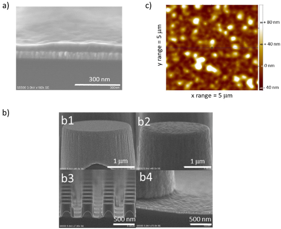 | ||
| Fig. 1 (a) SEM cross-sectional picture of ZIF-8@10_exposures. (b) SEM images of silicon pillars coated with ZnO by atomic layer deposition (b1) and the same pillars after 10 exposures of conversion in ZIF-8 (b2), (b3) and (b4). (c) AFM migrograph of ZIF-8@10_exposures (RMS of 25 nm). | ||
The AFM micrograph shows a root mean square (RMS) roughness of 25 nm (Fig. 1c), in line with roughness observed in the literature for samples with comparable thickness.18,35,36 The ZIF-8 formation is further confirmed by in-plane XRD analysis, infrared spectroscopy, XPS and TOF-SIMS. The diffraction peaks observed in the XRD analysis of the as-deposited sample after 10 exposures, ZIF-8@10_exposures, correspond to ZIF-8 sodalite type structure (Fig. 2a).37 No other polymorphs of the ZIF-8 are produced. Expected infrared vibrations of ZIF-8 are obtained in the FTIR spectra (see Fig. S3† and discussion therein). The XPS and TOF-SIMS data, discussed in the mechanism section below, further corroborate the formation of ZIF-8. When the as-deposited sample is exposed to thermal treatment under vacuum (see “activation procedure” in the Experimental section above), the relative intensity of the first peak (110) in the XRD diffractogram changes (Fig. 2a). Such phenomenon is attributed to the removal of disordered molecules from the material pores.38,39
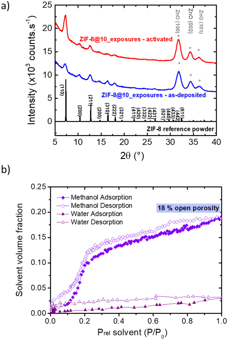 | ||
| Fig. 2 (a) In-plane XRD patterns of ZIF-8@10_exposures, as deposited (in blue) and after activation (in red), and a reference ZIF-8 signal from the data bank of DIFFRAC.EVA software (in black). (b) Adsorption and desorption methanol and water isotherms obtained by ellipsometry porosimetry at room temperature (22 °C) of the activated ZIF-8@10_exposures. | ||
Refractive Index (RI) of the layer is also modified by the activation from ∼1.50 after synthesis (see ESI† for detailed description, RI evaluated at 633 nm) to 1.36 after the thermal treatment at 280 °C. This value is close to those reported by Eslava et al. (1.34–1.35) for ZIF-8 layers between 400 nm and 1.4 μm synthetized by immersion of the substrate in a solvent containing the reagents.40 Cruz et al. evaluate the RI of thin ZIF-8 layer at 1.33 (∼30 nm).27 This low RI confirms the liberation of the porosity occurring after activation.
The porosity and adsorption properties of the films after activation were studied by ellipsometry–porosimetry (Fig. 2b). Using methanol as a probe molecule, a S-shape adsorption isotherm is observed with a maximum methanol volume fraction of 18% vol., which is in line with previous works on ZIF-8 thin films.40 The sample porosity was also probed using water adsorption, showing that a substantial amount of water is adsorbed (∼2.5% vol. at saturation pressure), even though this material is considered hydrophobic. This water adsorption capacity is higher than previously measured on ZIF-8 powder (H2O![[thin space (1/6-em)]](https://www.rsc.org/images/entities/char_2009.gif) :0.7% vol. and MeOH:38% vol. near saturation, recalculated from Zhang et al.41) and is to be correlated with the substantial presence of hydrophilic defects within the phase (see mechanism discussion below).
:0.7% vol. and MeOH:38% vol. near saturation, recalculated from Zhang et al.41) and is to be correlated with the substantial presence of hydrophilic defects within the phase (see mechanism discussion below).
Increase of ZIF-8 film thickness
Water plays an essential role in the growth of ZIF-8 from ZnO.18 Under dry conditions, the ZIF-8 thickness obtained by our process limited to a single exposure is low (∼5 nm) and can be increased with increasing water pressure, to reach 30–40 nm at pressure above 450 mbar (Fig. 3a, single exposure).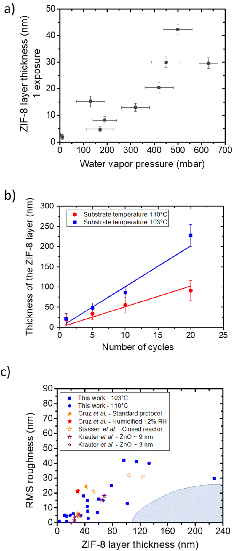 | ||
| Fig. 3 (a) ZIF-8 thicknesses obtained for reaction (1 exposure of 30 min) with different water vapor pressure at a substrate temperature of ∼103 °C. Horizontal error bars represent pressure variation during the experiment, and vertical error bars represent the fit uncertainty. (b) Evolution of the ZIF-8 layer thickness assessed by spectroscopic ellipsometry as a function of the number of exposures with PH2O = 400 mbar at a substrate temperature of 110 °C (red circles) and 103 °C (blue squares). The error bars correspond to the standard deviation of the thickness obtained from several runs (typically 2–4 samples). (c) Chart of thicknesses (nm) vs. RMS roughness (nm) of ZIF-8 layers obtained in this work (blue) and reported in the literature (from ref. 35 in red, ref. 18 in orange, and ref. 36 in purple). Shaded area highlights yet unreported samples combining thickness with smoothness. | ||
A substantial increase in the ZIF-8 thickness is observed as the number of reactive exposures is increased (10 ± 2 nm per exposure at a substrate temperature of 103 ± 4 °C, see Fig. 3b). Higher substrate temperature decreases the reaction rate (Fig. 3b), as already observed by Stassen et al.18 The best conditions we explored are 20 reactive exposures with the substrate at 103 ± 4 °C, which lead to a thickness of 230 ± 25 nm. At high H2O pressure, ellipsometric data became impossible to fit. This is linked to increased roughness, as already reported elsewhere.18 At the same time, the samples obtained herein represent an improvement with respect to the state of the art in terms of combined increased thickness and reduced roughness (Fig. 3c), although this approach does not completely limit the roughness for thick samples. Unfortunately, this significant surface roughness induces an important uncertainty on the determination of the refractive index (see details in the ESI†). This prevents a careful determination by ellipsometry-porosimetry of the impact of exposure number on the porosity.
Depth profiles of growing ZIF-8 phases
In order to investigate if this thickness limitation was connected to intrinsic mechanistic features, the depth profiles of characteristic samples were investigated by TOF-SIMS and XPS. The diffusion rate of the incoming vapor phase ligand 2-methylimidazole (MeIm-H) in the growing ZIF-8 phase was also investigated by molecular dynamics.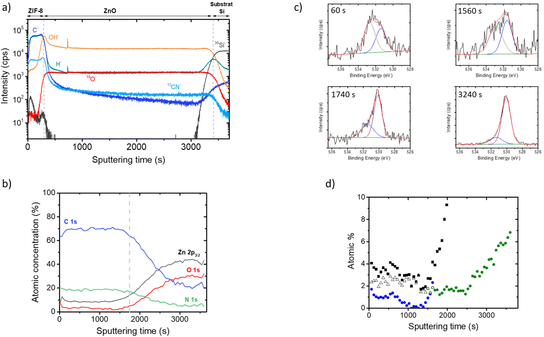 | ||
| Fig. 4 (a) TOF-SIMS profile of the stack ZIF-8/ZnO/Si in ZIF-8@3_exposures, (b) XPS atomic concentration profile of a ZIF-8/ZnO/Si in ZIF-8@5_exposures, (c) examples of the O 1s peak deconvolution at different sputtering times (60 s and 1560 s correspond to the ZIF layer, 1740 s corresponds to the appearance of ZnO and 3240 s is closer to the ZnO layer), (d) O atomic concentration profile (black squares), ZnOH2 contribution to the O 1s peak (white triangles, ∼533 eV), and ZnOH contribution to the O 1s peak (blue circles). In the ZnO region (sputtering time >1740 s), ZnOH (green circles) is detected in addition to the Zn–O bonds. | ||
In the ZnO region, fairly uniform distribution for all complexes ions can be recognized. The presence of Zn–OH indicates that the ZnO layer contained a relatively constant level of hydroxyl groups in its bulk. This result is in good agreement with previous papers showing the presence of Zn–OH bonds in a ZnO deposited by ALD at 150 °C from diethylzinc and deionized water.42 It is worth noting, that the OH− and the ZnOH− ions present a maximum enrichment at the interface between the ZIF and the ZnO layers. These signals are also present in the ZIF-8 layer: they decrease from the maximum value around the ZnO/ZIF-8 interphase to the minimum value close to the ZIF-8 surface. This minimum value is lower than that of the residual Zn–OH present in the ZnO phase grown by ALD.
For ZIF-8, all expected features are observed, including zinc, nitrogen, and carbon (see ESI† for detailed description). A low intensity O 1s region is also observed and can be decomposed into two contributions (Fig. S7†). A first one at 531.5 eV can be attributed to Zn-bonded hydroxyls (or eventually carbonates) in ZIF-8.48 A smaller contribution at a higher binding energy (533 eV) is attributed to chemisorbed species such as water or carbonates. No ZnO residue seems present at the surface of ZIF-8 as evidenced by the absence of O–Zn contribution around 530.1 eV.
The obtained atomic ratios are relatively uniform in depth and the composition is close to those detected at the surface. In this region, the oxygen content is low and the O 1s spectrum can be deconvoluted into two peaks (Fig. 4d) related to Zn–OH (∼531.5 eV) and to adsorbed water (∼532.7 eV). These different contributions are plotted as a function of the sputtering time in Fig. 4c. The Zn–OH contribution is lower than those of adsorbed water and decreases as we go deeper into the ZIF layer. After ∼1800 s of sputtering, the oxygen content increases rapidly indicating that the ZnO layer start to appears. The O 1s spectra of this interface zone can be deconvoluted into two components: one peak at 530.1 eV associated to ZnO and a peak at 531.6 eV attributed to Zn–OH (Fig. 4d). A contribution related to adsorbed water cannot be completely excluded but the use of an additional peak at high binding energy does not improve significantly the fit. Fig. 4c shows that the Zn–OH concentration increases substantially at the vicinity of the interface between ZIF-8 and ZnO. These XPS data are in good agreement with the ToF-SIMS profiles discussed previously, confirming the presence of Zn–OH groups in each region of the stack (ZIF-8 and ZnO) and a significant enrichment at the interface.
Molecular dynamics simulations
Molecular dynamics (MD) simulations were performed to investigate the impact of hydroxyl groups in the ZIF-8 phase on the rate of diffusion of imidazole through the porous structure itself. Specifically, three different MD simulations were conducted in order to compare the dynamic behavior of a single MeIm-H molecule within hydroxyl-free, that is pristine, ZIF-8 with respect to the dynamic behavior of MeIm-H within hydroxyl-rich, that is defective, ZIF-8 frameworks. These hydroxyl sites have been previously shown to be thermodynamically favored, as arising from missing-linker defects, formed by a water molecule together with an OH group replacing the MeIm linker.50 In the present work, two defective phases were investigated with 5% and 15% of missing linkers, respectively. The positions of missing linkers were randomly assigned within a 2 × 2 × 2 supercell of defect-free ZIF-8 using a Monte-Carlo approach (see ESI†). Each of the two Zn centers involved in each missing-linker defect was then saturated with a hydroxo and an aqua ligand, respectively. The two defective supercells were geometry-optimized allowing the relaxation of all atom positions before exploring the diffusion of a randomly introduced MeIm-H molecule through MD simulations (Fig. 5). Snapshots of the three simulated systems, i.e. the pristine and defective structures, are compiled in Fig. S8.† | ||
| Fig. 5 (a) Mean Square Displacement (MSD) of MeIm-H inside pristine ZIF-8 (black line) and defective ZIF-8 containing 5% and 15% missing linkers (blue and red lines, respectively), averaged over 5 ns of MD simulation. (b) Overlay of snapshots extracted from the MD simulation of MeIm-H inside the 15% defective ZIF-8, showing the migration of MeIm-H from one cage to another. Only two cages of the MOF are represented for clarity. (c) Dimensions (Å) of MeIm-H and (d and e) Dimensions of the windows connecting two cages of pristine ZIF-8 (d) and ZIF-8 (15% defects) (e), estimated from a Conolly surface analysis. The geometry of the cage in panel (e) was taken from a snapshot of the simulation in which MeIm-H is crossing through the window. | ||
Visual inspection of the MD trajectories revealed that MeIm-H is trapped inside a single cage of the defect-free MOF along the whole simulation run, whereas it diffuses through different cages (i.e. across the windows of the MOF) in the defective ZIF-8 models (Fig. 5b). This is further illustrated by the comparison of the Mean Square Displacement (MSD) of MeIm-H obtained from the simulations with the three analyzed MOF compositions (Fig. 5a). The MSD represents the deviation of the MeIm-H position (r) with respect to a reference position over time, averaged over the ensemble composed by all the time periods of Δt length obtained from the overall 5 ns of MD simulation, as shown in eqn (1):
| MSD = 〈|r(Δt) − r(0)|2〉 | (1) |
In all systems, the MSD displays a short (t < 5 ps) ballistic regime from 0 to ca. 35 Å2 (Fig. 5a), which accounts for the mobility of the imidazole molecule within a single cage of ZIF-8. In the defect-free ZIF-8 (Fig. 5a, black line), this is followed by a plateau in the MSD, showing that MeIm-H does not visit any other cage than the initial one. Conversely, a diffusive regime (MSD(Δt) linear in time with a slope >0) is observed for the two defect-containing ZIF-8 (Fig. 5a, blue and red lines).
Mechanistic insight
 | (2) |
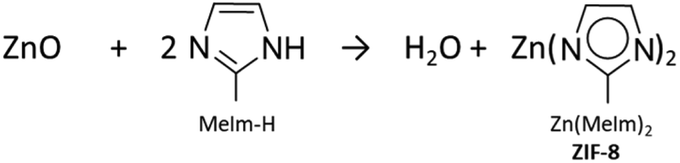
While the stoichiometry is correct, this proposal can only be read as a first and balanced equation, but is not very informative regarding the underlying growth. In fact, several points of attention become apparent when addressing the reaction from a mechanistic point of view, rather than just overall stoichiometry. Firstly, the repeating molecular motif in ZIF-8 is centered around a tetrahedral zinc coordinated to four imidazolates, not two as the eqn 2 might suggest at first reading. The reaction also suggests ZnO as a reactant. However, the MOF-CVD reaction probably takes place at the interface of the two phases, as well established for most heterogeneous gas/solid reactions. The surface zinc species, and a fortiori the most reactive ones, which are those to be considered first in a mechanistic study, are not necessarily well represented by ZnO. Several works have focused on the surface state of ZnO deposited by ALD. Boryło et al. probed the surface by XPS and found a carbon-rich composition (45%) while oxygen and zinc only represent about 22% and 33% respectively.42 Hydroxyls as well as chemisorbed species (water, carbonates) are observed in works examining the surface state of ZnO (not necessarily synthesized by ALD).18,43,47 These surface species are expected to be important in the reaction with the ligand. Khaletskaya et al. also demonstrated that the morphology of the starting ZnO influenced the growth of ZIF-8 layers.51
In contrast, the formation of Pt-ZIF-8 from Pt-doped zinc oxide powder deduced from thermogravimetric analysis (TGA) measurements shows that the conversion rate for the wet atmosphere experiment is lower than under dry conditions (about 8%), while other conditions (under air, vacuum or N2) lead to conversion rates in the range of 12–13%. The assumption given is that water competes with the ligand for the coordination of the metal centers and that excess water would shift the equilibrium of the formation reaction to Pt-doped ZIF-8.52 The effect of the addition of water vapor during the ZIF-8 formation reaction is therefore unclear. Even if some hypotheses have been proposed to justify the role of water vapor in the reaction and consider in particular that a starting ZnO layer rich in hydroxyl groups favors the conversion to ZIF-8, no fine analysis to identify and follow the evolution of these groups during the reaction has been implemented.
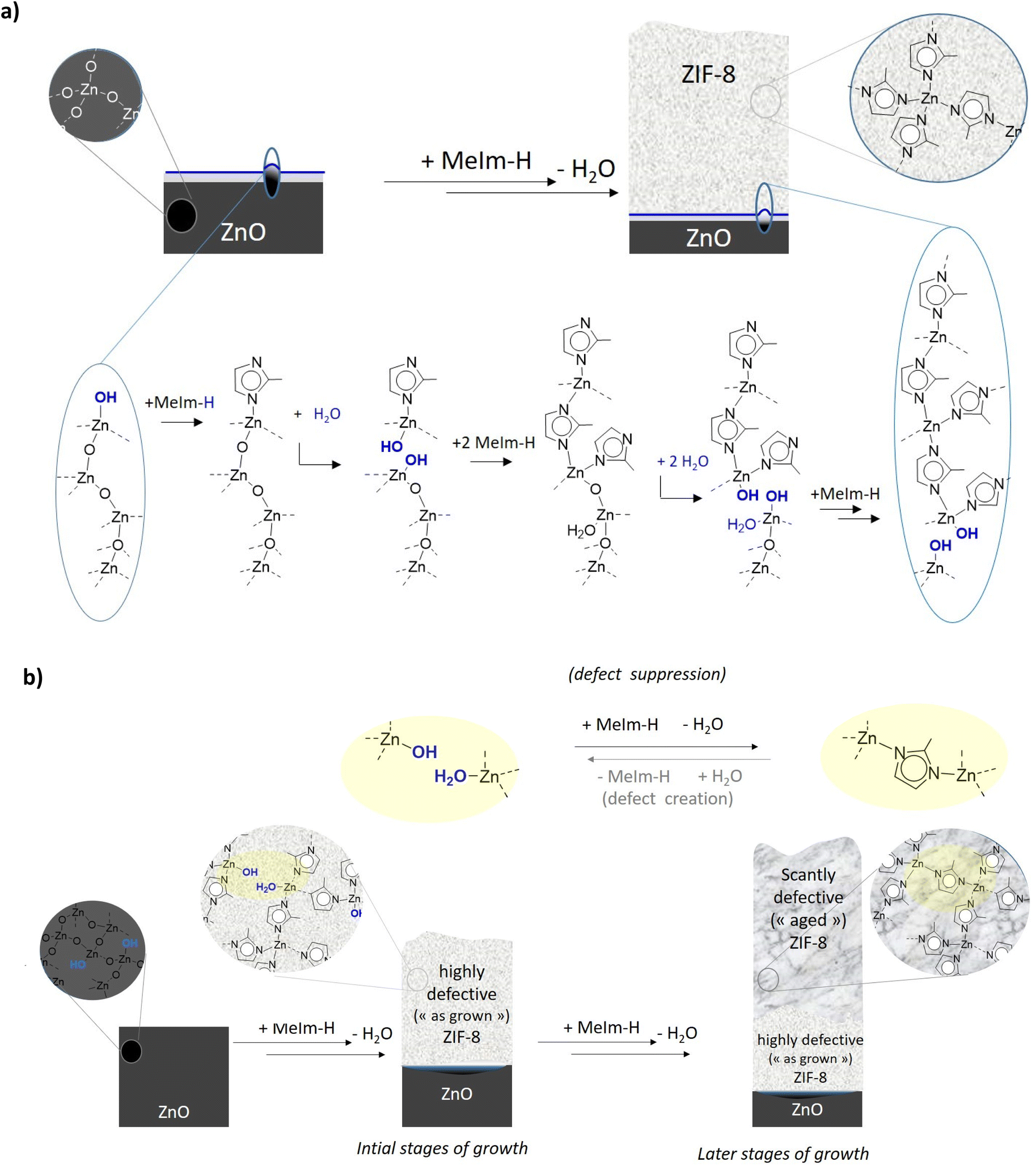 | ||
| Scheme 1 (a) Proposed idealized reaction mechanism involved in the growth of a defect-free ZIF-8 layer from exposure of a crystalline ZnO layer to vapor pressure of 2-methylimidazole linker, (b) proposed mechanism for defect curing occurring by incoming imidazole on originally defective (as grown) ZIF-8 in agreement with the experimental observed hydroxyls within the MOF layer and bulk ZnO. | ||
In agreement with the experimental impossibility to grow thick ZIF-8 layers without external water addition, molecular dynamics simulations suggest that imidazole linker cannot diffuse in pristine ZIF-8 (see black curve, Fig. 5a). A Conolly surface analysis was further done to compare the bulkiness of MeIm-H with the width of the windows that connect neighboring cages of the MOF (Fig. 5c–e). To do so, single cages of the pristine MOFs were extracted from representative snapshots of the simulations. As shown in Fig. 5d, the windows of the defect-free MOF are rather circular and too narrow to allow MeIm-H to pass through (Fig. 5c). In the presence of defects, i.e. water and –OH groups, these windows can eventually enlarge enough to allow the diffusion of MeIm-H from one cage to another (compare MeIm-H dimensions in Fig. 5c with the width of the window in Fig. 5e). The mean square displacement of imidazole in defective ZIF-8 (see red and blue curves in Fig. 5a) similarly demonstrates that MeIm-H can indeed diffuse through ZIF-8 porous network in the presence of defects as missing linkers, which may be experimentally obtained in the early stages of ZIF-8 growth close to the ZnOH/ZnO interface (or by treating the MOF with water vapor, vide supra). Importantly, as this slope is directly proportional to the diffusion coefficient, the higher slope of the MSD diffusive regime obtained for ZIF-8 with 15% of defects when compared to that with only 5% of defects indicates that indeed, the diffusion of MeIm-H through ZIF-8 increases with the number of missing linkers thanks to the increasing number of pore windows with larger openings. This is also consistent with previous computational studies, which reported that the presence of defects in ZIF-8 facilitates the window crossing of a series of adsorbates by increasing the local hoping rate for molecular diffusion.53 Here, four “crossing” events in which MeIm-H travels across the window that connects two neighboring cages were accordingly observed in the ZIF-8 model with 15% of defects (at t = 125, 800, 2120 and 2825 ps), while only two of them (at t = 1720 and 3205 ps) were found when the number of defects is decreased to 5%. Fig. 5b illustrates such a crossing event observed over the MD simulation with 15% of defects. Thus, one may conclude that one key role of defects in the growing mechanism of ZIF-8 is to provide diffusion path to MeIm-H molecules from the MOF surface to the MOF–ZnO interphase, where they then react to increase the thickness of the MOF layer. Conversely, a pure defect-free phase would hamper this diffusion of the linker toward the interphase.
While defective (hydroxyl) ZIF-8 are likely to grow close to the hydroxyl-rich interphase with Zn–O, the growth process itself which implies the diffusion of ligand vapor phase through the pores thus exposes these defects to a “repair” reaction (see Scheme 1b), whereby a H2O/OH pair is replaced by a bridging linker. This is equivalent to curing the defects and hence leading to a stunted growth. Under certain conditions, the addition of water can repristinate the defects and prolong the growth range of the ZIF-8. Yet, along the process, when the growing phase becomes sufficiently defect-free to become sufficiently hydrophobic (as pristine crystalline ZIF-8 is), to quell window crossing by water,53 external water addition is not possible and the upper limit for material growth is reached.
To agree with coordination chemistry principles as well with the known water resistance of crystalline ZIF-8, this hypothesis calls for water displaceable zinc coordinated imidazole-based linker under the form, for example, of a mono coordinated species (such as neutral imidazole Zn(NC4H5NH) or anionic imidazolate Zn(NC4H5N|) with a free doublet on the zinc-free nitrogen (N|) which offers an alternative to the water-resistant bridging linkers present in ZIF-8 (Zn(NC4H5N)Zn). Interestingly, one or both of the proposed monocoordinated species listed above are expected to be intermediates of the defect suppression reaction presented in Scheme 1b. This rationalization could lend itself to give some mechanistic explanation to the known fact that ZIF-8 growth by wet imidazole exposure of ZnO cannot be resumed by reintroducing a previously dried sample to a reactive atmosphere. Furthermore, this role could offer a rationale for the efficiency of our cyclic pulsing process, which pointedly avoids such dehydration step while offering some defect reintroduction by cycling water exposure, especially when the crystallization has not completely settled in, leaving water-displaceable zinc-coordinate imidazole still in the growing phase.
A last consequence of the introduction of water, which is mentioned in the literature but not explained, is the maturation of the crystals. This maturation or enlargement of crystals could result from the same phenomenon of creation of defects and then “repair” that is promoted by water. Water brings sufficient mobility to the 2-methylimidazole and creates Zn–OH bonds which are reactive. The coarsening and reorganization of the crystals would result in the roughness observed for layers that were synthesized with water or that were exposed to water vapor after synthesis.27
The studies presented here also tie in with the mechanistic hypotheses put forward to explain the central role played by water in the ZIF-8 phase growth. Most hypotheses in literature addressing the role of water in the ZIF growth focus on the ZIF-8/ZnO interphase as an enabler of reagent/MOF building -block mobility at interphase18,27 and/or as co-source of necessary interphase hydroxyls and hydration.18 Herein a further role for water in the growth mechanism can be proposed related to the possibility to shift the position of the equilibrium between defect-rich and defect-poor ZIF-8 phases. Water could displace zinc-coordinated imidazole-based linker and hence prevent the formation of defect-free growth-suppressant ZIF-8.
An intriguing further role of water proposed elsewhere for this process is the increase of the final roughness of the sample (Fig. S9†). A possible explanation has been offered, with the persistent presence of water formed at the ZnO/ZIF-8 interphase, due to its incapacity to leave the interphase.18 The mechanism proposed herein suggests that the incapacity for water to diffuse rapidly off the interphase is linked to the increasing crystallinity of the superior aged-hence cured-ZIF-8 layer. If it is true that the roughness is indeed due to water impossibility to diffuse from the interphase, our mechanistic proposal here suggests that the concomitant undesirable phenomena of self-limitation growth and roughness increase might be intimately intertwined and attempting to solve one without addressing the other might be an arduous, if at all possible, task. Our molecular-level mechanism does not take into account intergrain surface chemistry occurring in polycrystalline samples like ours, which could affect the final observed roughness. In summary, while thicker and as-rough-as-before layers have been obtained, the ideal targeted double goal of growing thicker and smoother layer does not appear to be within the reach of this approach for mechanistic reasons due to the approach itself.
Conclusions
In this work, an improved process for ZIF-8 thin film realization is described, based on repeated exposure to ligand and water of a ZnO sacrificial layer. This approach allows the control of the thickness of the film up to 230 nm. Molecular composition of the film was probed in depth by XPS and TOF-SIMS, highlighting the presence of Zn–OH groups in each region of the stack (ZIF-8 and ZnO) and a significant enrichment at the interface. Experimental data and molecular dynamics simulations suggested that the Zn–OH defects in the ZIF-8 layer are in fact mandatory to allow diffusion of the ligand to the growing interface. These elements tend to explain the efficiency of our cycling process. At the same time, this insight suggests a limit to growth which is consubstantial with the method proposed: upon growth, the top layer of the growing ZIF film, that is the one closer to the ultimate surface, is cured from its initial defects present closer to the ZnO/ZIF-8 interphase. Due to the topology of the ZIF-8 and in particular to the fact that the window diameter of the crystalline material is smaller than the diameter of the free ligand, such aspect of the ageing process becomes a physical barrier to the diffusion and hence the further growth of the material. The take home message is that ZIF-8 layers that can be obtained through this direct method are inherently barred from being thick and reasonably defect-free at the same time. While the water cycling that we have devised pushes back some of these limitations, it cannot overcome them. Our work suggests that more subtle approaches are necessary for this fabrication approach of this type of MOF (nanopatterning of the starting substrate, process engineering limiting the curing reaction without disrupting the growth, annealing process unlocking these limitations, etc.). This will allow to help further the development of MOF thin film deposition processes, en route to vapor phase fabrication methods capable of unlocking the potential of these materials in microelectronics.Author contributions
VJ conceptualized and managed the project with EAQ, AR and FR. V P did the material synthesis, ellipsometry, ellipsometry porosimetry, FTIR, SEM and participated to all the other experiments. MV performed ToF-SIMS experiments, AB did the XPS measurements and DM performed the AFM experiments. VP treated all experimental data under the supervision of VJ, AR and EAQ. All the authors contributed to analyze the data. The simulations were performed by AS-D and CM-D. The paper was written by VP, AR, AS-D, CM-D, EAQ and VJ. All authors have given their approval to the final version of the manuscript.Conflicts of interest
There are no conflicts to declare.Acknowledgements
The authors thank T. Julien and G. Castellan for ALD depositions, B. Assie for the technical support on the conversion reactor, C. Licitra for the support on ellipsometry measurements, N. Rochat for her help on FTIR experiments and P. Gergaud for XRD measurements. This work was initiated in the framework of the ‘nano-chemistry platform’ partnership between the C2P2 research unit, initial address of authors VP et EAQ, and the “Direction de la Recherche Technologique” (DRT) of CEA. The C2P2 unit (UMR 5265) has since merged in the CP2M research unit (UMR 5128), both under CNRS, CPE Lyon and Université Claude Bernard Lyon 1 tutelage. Part of this work, carried out on the Platform for Nanocharacterization (PFNC), was supported by the ‘Recherches Technologiques de Base’ program.References
- M. D. Allendorf, R. Dong, X. Feng, S. Kaskel, D. Matoga and V. Stavila, Chem. Rev., 2020, 120, 8581–8640 CrossRef CAS PubMed.
- M. Jenkins, D. Z. Austin, J. F. Conley, J. Fan, C. H. de Groot, L. Jiang, Y. Fan, R. Ali, G. Ghosh, M. Orlowski and S. W. King, ECS J. Solid State Sci. Technol., 2019, 8, N159 CrossRef CAS.
- C. Sanchez, B. Julián, P. Belleville and M. Popall, J. Mater. Chem., 2005, 15, 3559–3592 RSC.
- A. Grill, S. M. Gates, T. E. Ryan, S. V. Nguyen and D. Priyadarshini, Appl. Phys. Rev., 2014, 1, 011306 Search PubMed.
- V. Jousseaume, J. El Sabahy, C. Yeromonahos, G. Castellan, A. Bouamrani and F. Ricoul, Microelectron. Eng., 2017, 167, 69–79 CrossRef CAS.
- K. Sumida, D. L. Rogow, J. A. Mason, T. M. McDonald, E. D. Bloch, Z. R. Herm, T.-H. Bae and J. R. Long, Chem. Rev., 2012, 112, 724–781 CrossRef CAS PubMed.
- E. Barea, C. R. Montoro and J. A. Navarro, Chem. Soc. Rev., 2014, 43, 5419–5430 RSC.
- J.-R. Li, R. J. Kuppler and H.-C. Zhou, Chem. Soc. Rev., 2009, 38, 1477 RSC.
- S. Qiu, M. Xue and G. Zhu, Chem. Soc. Rev., 2014, 43, 6116–6140 RSC.
- U. P. N. Tran, K. K. A. Le and N. T. S. Phan, ACS Catal., 2011, 1, 120–127 CrossRef CAS.
- S. Aguado, J. Canivet and D. Farrusseng, J. Mater. Chem., 2011, 21, 7582 RSC.
- J. Liu, L. Chen, H. Cui, J. Zhang, L. Zhang and C.-Y. Su, Chem. Soc. Rev., 2014, 43, 6011–6061 RSC.
- W.-T. Koo, J.-S. Jang and I.-D. Kim, Chem, 2019, 5, 1938–1963 CAS.
- G. Lu and J. T. Hupp, J. Am. Chem. Soc., 2010, 132, 7832–7833 CrossRef CAS PubMed.
- A. Bétard and R. A. Fischer, Chem. Rev., 2012, 112, 1055–1083 CrossRef PubMed.
- I. Stassen, N. Burtch, A. Talin, P. Falcaro, M. Allendorf and R. Ameloot, Chem. Soc. Rev., 2017, 46, 3185–3241 RSC.
- K. S. Park, Z. Ni, A. P. Cote, J. Y. Choi, R. Huang, F. J. Uribe-Romo, H. K. Chae, M. O'Keeffe and O. M. Yaghi, Proc. Natl. Acad. Sci. U. S. A., 2006, 103, 10186–10191 CrossRef CAS PubMed.
- I. Stassen, M. Styles, G. Grenci, H. V. Gorp, W. Vanderlinden, S. D. Feyter, P. Falcaro, D. D. Vos, P. Vereecken and R. Ameloot, Nat. Mater., 2016, 15, 304–310 CrossRef CAS PubMed.
- P. Xu, M. Liu, X. Li, T. Xu and Y. Zhang, 2017 19th International Conference on Solid-State Sensors, Actuators and Microsystems (TRANSDUCERS), IEEE, Kaohsiung, 2017, pp. 762–765 Search PubMed.
- N. Paknameh, S. Fatemi and M. Razavian, Mater. Chem. Phys., 2019, 235, 121764 CrossRef CAS.
- W. Li, P. Su, Z. Li, Z. Xu, F. Wang, H. Ou, J. Zhang, G. Zhang and E. Zeng, Nat. Commun., 2017, 8, 406 CrossRef PubMed.
- B. Reif, J. Somboonvong, F. Fabisch, M. Kaspereit, M. Hartmann and W. Schwieger, Microporous Mesoporous Mater., 2019, 276, 29–40 CrossRef CAS.
- W. A. Amer, J. Wang, B. Ding, T. Li, A. E. Allah, M. B. Zakaria, J. Henzie and Y. Yamauchi, ChemSusChem, 2020, 13, 1629–1636 CrossRef CAS PubMed.
- Y. Li, H. Xie, J. Li, Y. Bando, Y. Yamauchi and J. Henzie, Carbon, 2019, 152, 688–696 CrossRef CAS.
- R. Bo, M. Taheri, B. Liu, R. Ricco, H. Chen, H. Amenitsch, Z. Fusco, T. Tsuzuki, G. Yu, R. Ameloot, P. Falcaro and A. Tricoli, Adv. Sci., 2020, 7, 2002368 CrossRef CAS PubMed.
- S. Tanaka, K. Kida, T. Nagaoka, T. Ota and Y. Miyake, Chem. Commun., 2013, 49, 7884 RSC.
- A. J. Cruz, I. Stassen, M. Krishtab, K. Marcoen, T. Stassin, S. Rodríguez-Hermida, J. Teyssandier, S. Pletincx, R. Verbeke, V. Rubio-Giménez, S. Tatay, C. Martí-Gastaldo, J. Meersschaut, P. M. Vereecken, S. De Feyter, T. Hauffman and R. Ameloot, Chem. Mater., 2019, 31, 9462–9471 CrossRef CAS.
- C. Licitra, F. Bertin, M. Darnon, T. Chevolleau, C. Guedj, S. Cetre, H. Fontaine, A. Zenasni and L.-L. Chapelon, Phys. Status Solidi C, 2008, 5, 1278–1282 CrossRef CAS.
- Accelrys (2016) Materials Studio. https://Accelrys.Com/Products/Collaborative-Science/Biovia-Materials-Studio/.
- A. K. Rappe, C. J. Casewit, K. S. Colwell, W. A. Goddard and W. M. Skiff, J. Am. Chem. Soc., 1992, 114, 10024–10035 CrossRef CAS.
- H. T. Kwon, H.-K. Jeong, A. S. Lee, H. S. An and J. S. Lee, J. Am. Chem. Soc., 2015, 137, 12304–12311 CrossRef CAS PubMed.
- S. A. Nosé, J. Chem. Phys., 1984, 81, 511–519 CrossRef.
- T. Darden, D. York and L. Pedersen, J. Chem. Phys., 1993, 98, 10089–10092 CrossRef CAS.
- A. K. Rappe and W. A. Goddard, J. Phys. Chem., 1991, 95, 3358–3363 CrossRef CAS.
- A. J. Cruz, G. Arnauts, M. Obst, D. E. Kravchenko, P. M. Vereecken, S. De Feyter, I. Stassen, T. Hauffman and R. Ameloot, Dalton Trans., 2021, 50, 6784–6788 RSC.
- A. J. Kräuter, T. Cruz, S. Stassin, R. Rodríguez-Hermida, R. Ameloot, R. Resel and A. M. Coclite, Crystals, 2022, 12, 217 CrossRef.
- H. McMurdie, M. Morris, E. Evans, B. Paretzkin, W. Wong-Ng, L. Ettlinger and C. Hubbard, Powder Diffr., 1986, 1, 66–76 CrossRef.
- D. Esken, H. Noei, Y. Wang, C. Wiktor, S. Turner, G. Van Tendeloo and R. A. Fischer, J. Mater. Chem., 2011, 21, 5907 RSC.
- S. B. Kalidindi, D. Esken and R. A. Fischer, Chem. – Eur. J., 2011, 17, 6594–6597 CrossRef CAS PubMed.
- S. Eslava, L. Zhang, S. Esconjauregui, J. Yang, K. Vanstreels, M. R. Baklanov and E. Saiz, Chem. Mater., 2013, 25, 27–33 CrossRef CAS.
- K. Zhang, R. P. Lively, M. E. Dose, A. J. Brown, C. Zhang, J. Chung, S. Nair, W. J. Koros and R. R. Chance, Chem. Commun., 2013, 49, 3245 RSC.
- P. Boryło, K. Matus, K. Lukaszkowicz, J. Kubacki, K. Balin, M. Basiaga, M. Szindler and J. Mikuła, Appl. Surf. Sci., 2019, 474, 177–186 CrossRef.
- C. Woll, Prog. Surf. Sci., 2007, 82, 55–120 CrossRef.
- R. Viter, I. Iatsunskyi, V. Fedorenko, S. Tumenas, Z. Balevicius, A. Ramanavicius, S. Balme, M. Kempiński, G. Nowaczyk, S. Jurga and M. Bechelany, J. Phys. Chem. C, 2016, 120, 5124–5132 CrossRef CAS.
- N. Asakuma, T. Fukui, M. Toki, K. Awazu and H. Imai, Thin Solid Films, 2003, 445, 284–287 CrossRef CAS.
- M. C. Biesinger, L. W. M. Lau, A. R. Gerson and R. S. C. Smart, Appl. Surf. Sci., 2010, 257, 887–898 CrossRef CAS.
- J. T. Newberg, C. Goodwin, C. Arble, Y. Khalifa, J. A. Boscoboinik and S. Rani, J. Phys. Chem. B, 2018, 122, 472–478 CrossRef CAS PubMed.
- F. Tian, A. M. Cerro, A. M. Mosier, H. K. Wayment-Steele, R. S. Shine, A. Park, E. R. Webster, L. E. Johnson, M. S. Johal and L. Benz, J. Phys. Chem. C, 2014, 118, 14449–14456 CrossRef CAS.
- F. Tian, A. M. Mosier, A. Park, E. R. Webster, A. M. Cerro, R. S. Shine and L. Benz, J. Phys. Chem. C, 2015, 119, 15248–15253 CrossRef CAS.
- C. Zhang, C. Han, D. S. Sholl and J. R. Schmidt, J. Phys. Chem. Lett., 2016, 7, 459–464 CrossRef CAS PubMed.
- K. Khaletskaya, S. Turner, M. Tu, S. Wannapaiboon, A. Schneemann, R. Meyer, A. Ludwig, G. Van Tendeloo and R. A. Fischer, Adv. Funct. Mater., 2014, 24, 4804–4811 CrossRef CAS.
- B. Yi, H. Zhao, Y. Zhang, X. Si, G. Zhang, Y. An, L. Su, C.-K. Tsung, L.-Y. Chou and J. A. Xie, Chem. Commun., 2021, 57, 3587–3590 RSC.
- C. Han, R. J. Verploegh and D. S. Sholl, J. Phys. Chem. Lett., 2018, 9, 4037–4044 CrossRef CAS PubMed.
Footnotes |
| † Electronic supplementary information (ESI) available. See DOI: https://doi.org/10.1039/d3nr00404j |
| ‡ Present address: Van't Hoff Institute for Molecular Sciences, University of Amsterdam, 1098 XH Amsterdam, The Netherlands. |
| This journal is © The Royal Society of Chemistry 2023 |