
 Open Access Article
 This Open Access Article is licensed under a
 Creative Commons Attribution 3.0 Unported Licence
MgO nanocube hydroxylation by nanometric water films†
N. Tan
Luong
 ,
Michael
Holmboe
and
Jean-François
Boily
*
,
Michael
Holmboe
and
Jean-François
Boily
*
Department of Chemistry, Umeå University, SE 901 87 Umeå, Sweden. E-mail: jean-francois.boily@umu.se
First published on 11th May 2023
Abstract
Hydrophilic nanosized minerals exposed to air moisture host thin water films that are key drivers of reactions of interest in nature and technology. Water films can trigger irreversible mineralogical transformations, and control chemical fluxes across networks of aggregated nanomaterials. Using X-ray diffraction, vibrational spectroscopy, electron microscopy, and (micro)gravimetry, we tracked water film-driven transformations of periclase (MgO) nanocubes to brucite (Mg(OH)2) nanosheets. We show that three monolayer-thick water films first triggered the nucleation-limited growth of brucite, and that water film loadings continuously increased as newly-formed brucite nanosheets captured air moisture. Small (8 nm-wide) nanocubes were completely converted to brucite under this regime while growth on larger (32 nm-wide) nanocubes transitioned to a diffusion-limited regime when (∼0.9 nm-thick) brucite nanocoatings began hampering the flux of reactive species. We also show that intra- and inter-particle microporosity hosted a hydration network that sustained GPa-level crystallization pressures, compressing interlayer brucite spacing during growth. This was prevalent in aggregated 8 nm wide nanocubes, which formed a maze-like network of slit-shaped pores. By resolving the impact of nanocube size and microporosity on reaction yields and crystallization pressures, this work provides new insight into the study of mineralogical transformations induced by nanometric water films. Our findings can be applied to structurally related minerals important to nature and technology, as well as to advance ideas on crystal growth under nanoconfinement.
Introduction
Mineral particles exposed to air moisture stabilize thin water films that drive solvent-mediated reactions under nanoconfinement.1–3 These films can affect chemical, structural, and functional properties of minerals in unique ways.2–7 Understanding mineralogical transformations in water films can especially be useful in addressing phenomena related to atmospheric chemistry, catalysis, electrochemistry, geochemistry, and surface science.8–12Periclase (MgO; magnesia) is an ideal hydrophilic mineral13,14 for tracking water film-driven transformations,6,15 as its rock salt structure can readily transform to brucite nanosheets (MgO + H2O → Mg(OH)2) (Fig. 1). Transformations can be topotactic16 when water diffuses through the (111) plane of MgO, forming OH groups along the (001) plane of brucite (Fig. 1a). Because these transformations can be short-range, they can even produce intralaminar spacings intermediate to those of both minerals.16,17 At the same time, solution-driven transformations at dehydroxylated surfaces can begin with the protonation of oxo groups (H2O + Mg2+–O2− → MgOH+–OH−)18–21via dissociative water adsorption.22–24 Hydroxylated surfaces produce reactive soluble (e.g. Mg2+, MgOH+) species leading to Mg(OH)2 nanosheet nucleation and stacking (Fig. 1b). Brucite growth then expands the volume of the reactive solid materials by ∼150%. Under confinement, this volumetric expansion has the thermodynamic potential of generating GPa-level crystallization pressures.25 Expansion can crack MgO-based cements26 and refractory castables,27 and is of great interest in the study of reaction-induced fracturing in Earth's crust.12,25
 | ||
| Fig. 1 Brucite growth from periclase in nanometric water films. (a) Topotactic relationship between (left) the (111) plane of periclase and (right) the (001) plane of brucite (green = Mg2+, purple = O2−, black = H+). Hydroxylation expands the 〈111〉 direction by ∼50% but only ∼5% within the (111) plane (ρpericlase = 3.5 g cm−3; ρbrucite = 2.3–2.4 g cm−3), resulting in the d001-spacing value of d001 = 4.8 Å. Solvent-driven reactions involve (b) a nucleation-controlled regime hosting Mg2+ dissolution, nucleation and stacking of brucite nanosheets, and (c) or diffusion-controlled regime caused by brucite nanocoatings (green). These nanocoatings limit the diffusion of reactive species to the reactive MgO core (grey). | ||
In water-unsaturated environments, water films formed by exposure to atmospheric moisture can be sufficiently thick to mediate brucite growth via dissolution, hydroxylation, nucleation, and crystal growth (Fig. 1b). Reactions can therefore be comparable to those occurring in aqueous solutions, except that they proceed in the nearly two-dimensional environment of water films.20,28 Variations in periclase crystallinity, microporosity, and particle size can, additionally, give rise to a surprisingly wide range of hydroxylation rates, yields, and mechanisms.29–34 Exploring these variations in the low water-to-solid environment of water films is strongly needed, especially considering the widespread importance of periclase in industry,26,27,35,36 and emerging technologies planning to use MgO-bearing wastes for direct atmospheric CO2 capture from moist air.37
Advancing knowledge about these water film-mediated reactions can be achieved by working with synthetic periclase nanocubes with contrasting properties. In particular, synthetic periclase nanocubes tailored by controlled thermal dehydroxylation (Mg(OH)2 → MgO + H2O) are of great utility. When produced below ∼600–650 °C, synthetic periclase nanocubes are more reactive towards hydroxylation compared than those produced above this value.30,31 Nobel prize laureate William Giauque, who in the late 1940s studied MgO hydroxylation to investigate the third law of thermodynamics, explained enhanced MgO nanoparticle reactivity below this threshold temperature in terms of favorable surface energetics,29 and these were finally measured experimentally over 70 years later by Hayun et al.15 In the 1960s, Feitknecht and Braun32 suggested that microporosity favored reactivity, and that it was even responsible for generating high crystallization pressures. In the 1980s, Naono31 validated this link by revealing a systematic hike in microporosity with synthesis temperature, and a near-complete loss above this threshold temperature. At the same time, experimental and theoretical studies detailed the topotactic interconversion of periclase and brucite in near in vacuo conditions,16,17,38,39 as well as morphological transformations and thermodynamics in aqueous solutions.33,40,41 More recently, water films were even shown to drive aggregation of periclase nanocubes into nanobars,3,42,43 a discovery that contributed greatly to ideas on crystal growth by (oriented) aggregation. Less remains, however, understood about mechanisms in nanometrically thin water films that can drive solution-like brucite formation, yet that are insufficiently thick to host vast pools of reactive species as in bulk water. Under these conditions, growth may be at first nucleation-controlled44 while Mg2+/MgOH+ species precipitate to brucite in water films (Fig. 1b). Growth may, however, become later diffusion-controlled45 as brucite nanocoatings hamper the flux of reactive species to growth fronts46 (Fig. 1c).
In this study, we offer new insight into the conversion of periclase by nanometrically thick water films, which were formed under environmental-relevant conditions of high humidity. This work fills a gap between previous efforts focused on low pressure/vacuum16,17,20,38,39,47 and aqueous systems,33,40,41 and by contrasting the reactivity of periclase nanocubes produced below and above the ∼600–650 °C threshold. We show that differences in nanocube size and microporosity have a direct impact on reaction yields and crystallization pressures during brucite growth. Our findings have direct implications in understanding water film-driven transformations of chemically and structurally related nanominerals (e.g. CaO, FeO). They also have broader implications for understanding mineral growth mechanisms under nanoconfinement.
Methods
Two periclase (MgO) samples of contrasting particle size and crystallinity were synthesized by thermal dehydroxylation of synthetic brucite (Mg(OH)2, Fig. S1†) at 500 °C (Pe5) and at 1000 °C (Pe10) for 2 h under ambient atmosphere. The ESI (Fig. S1–S3 and Tables S1, S2)† contains a detailed account on the synthesis procedures and physicochemical characterization results (structure, morphology, size, micropore analysis, surface composition).In this study, Pe5 and Pe10 nanocubes were exposed to a flow of 90% Relative Humidity (RH) in N2(g) at 25 °C. This gas composition was generated using a proUmid MHG32 instrument. Reactions were monitored in situ by X-ray diffraction (XRD), vibrational spectroscopy and microgravimetry, and ex situ by electron microscopy, thermal gravimetry and X-ray photoelectron spectroscopy (ESI†).
X-ray diffraction
Crystalline phase transformations were monitored by powder XRD on Pe5 and Pe10 samples exposed to a 250 mL min−1 flow of 90%RH. X-ray diffractograms were acquired with a PANalytical X'Pert3 powder diffractometer using an Anton Paar MHC-trans humidity chamber working in transmission. All diffractograms were collected within the 10–55° 2θ range because of the inherent limitations of working in transmission geometry. The sample stage was aligned along the vertical using corundum powder as a standard. This procedure was conducted prior all experiments to ensure that diffraction peaks did not shift from a misplaced sample stage. Periclase samples were thereafter placed on small cups assembled with a thin Kapton® film at the bottom for incoming X-rays. These cups were then placed on the rotatable sample stage of the transmission chamber. The samples were first dried with N2(g) for 1 h, and their XRD profile acquired. The samples were then exposed to 90%RH over 40 h period while XRD profiles were recorded every 2 h.Simulations of XRD profiles were performed using the Rietveld program BGMN®48 with the GUI software of Profex v4.1. Structure control files were converted from reference structure files from the American Mineralogist Crystal Structure database49 (0000501 for periclase50 and 0007912 for brucite51). Phase quantification by Rietveld refinement using the complete XRD profiles (10–55° 2θ) revealed considerable variations from an abnormal (001) reflection of brucite. Because attempts at using a brucite model with a broken symmetry did not extract meaningful phase quantification results, we limited our Rietveld refinement to the 30–46° 2θ range. This model converged to a stable solution with acceptable deviations (χ2 ≤ 1.5) to the data.
The resulting time-resolved Rietveld refinement results were modeled using kinetic growth models44 described in the ESI.† Briefly, an Avrami-type52,53 model was used to predict nucleation-limited growth in water films, and a Shrinking Core Model54 was used to predict diffusion-limited transport of reactive species to brucite growth fronts. These calculations were carried out using Matlab 2021b (The Mathworks).
Vibrational spectroscopy
Fourier transform infrared (FTIR) spectroscopy was used to monitor the surface hydration and hydroxylation of periclase to brucite. Thin dry periclase films were first formed by depositing, then drying, a centrifuged MgO-ethanol paste on the diamond window of an Attenuated Total Reflectance (ATR) cell (Golden Gate, a single bound diamond window). The resulting sample was then covered with a flow-through lid pressed on the ATR plate using an anvil. Liquid ethanol was thereafter removed from the paste using a stream of dry N2(g). Complete removal of ethanol was confirmed by tracking the loss of characteristic C–H stretching modes during drying. This procedure resulted in a packed solid-state film of periclase nanocubes on the ATR cell. Hydration and hydroxylation reactions were thereafter initiated by exposing the sample to 500 mL min−1 stream of 90%RH mixed with N2(g) for a period of up to 5 d.All spectra were acquired at a resolution of 4 cm−1 over the 600–4500 cm−1 range at a forward/reverse scanning rate of 10 kHz. These were obtained by coadding 500 spectra for Pe5 (7.5 min acquisition time) and 1000 spectra for Pe10 (15 min acquisition time) using a Bruker Vertex 70/V instrument. This instrument was equipped with a deuterated L-alanine doped triglycine sulfate (DLaTGS) detector.
Imaging
To image reaction products, periclase powder was reacted in a flow-through reaction vessel to a stream of 90% RH mixed with N2(g) for a period of up to 48 h. Samples were imaged by Scanning Electron Microscopy (SEM) and bright-field Transmission Electron Microscopy (TEM). SEM images were taken on a Carl Zeiss Merlin microscope while a FEI Talos L120 microscope (120 kV) was used for low-resolution TEM images. High-resolution transmission electron microscopy (HRTEM) images were taken under cryogenic conditions (−90 °C) to minimize well-known effects of electron beam damage on magnesium hydroxides.55,56 These images were acquired with a FEI Titan Krios electron microscope equipped with a field emission gun operated at 300 kV and a K2 detector.(Micro)Gravimetry
Water loadings acquired by Pe5 and Pe10 were determined by microgravimetry, using a DVS Advantage ET 2 instrument (Surface Measurement Systems). An aliquot of ∼10–20 mg periclase was first dried with N2(g) at 25 °C for 5 h. The weight of the resulting sample was then monitored in an 11-point adsorption isotherm from 0 to 95% RH, using an equilibrium period of 1 h at each preselected RH. In an additional experiment, Pe5 and Pe10 were exposed to 90% RH over a 40 h period. The reacted samples were then dried under N2(g) to determine the mass of the water film. The mass of Mg(OH)2 produced by these reactions was also determined by Thermal Gravimetry Analysis (TGA) on samples reacted under the same conditions. Samples were thermally decomposed using a Metter-Toledo TGA instrument under a stream of 20 mL min−1 N2(g) from 30–700 °C, and at a heating rate of 10 °C min−1.Results and discussion
To compare the reactivity of periclase produced below and above the ∼600–650 °C threshold, we synthesized periclase nanocubes by dehydroxylating brucite nanoparticles at 500 °C (Pe5) and 1000 °C (Pe10). Characterization results are given in Fig. 2 and in the ESI (Fig. S1–S4 and Tables S1, S2).† Pe5 nanocubes (Fig. 2a–e) were 8.2 ± 0.4 nm wide crystallites aggregated as nanobars in ∼77 ± 25 nm wide two-dimensional hexagonal casings. These casings were relicts of the brucite nanoparticles (Fig. S1†) from which Pe5 nanocubes formed in situ. The important volumetric compression undergone by the material during dehydroxylation produced a maze-like network of slit-shaped micropores which, from N2(g) adsorption/desorption (Fig. S3†), were the chief source of microporosity (26 μL g−1). Pe10 nanocubes (Fig. 2f–j) were, in contrast, 32 ± 2 nm wide monodispersed crystallites and were ∼8 times less microporous (3.3 μL g−1) than Pe5.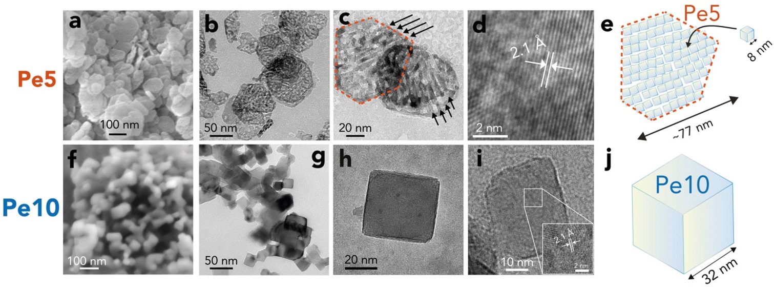 | ||
| Fig. 2 Periclase nanocube morphology and size. Electron microscopy images of (a–d) Pe5 and (f–i) Pe10, alongside (e and j) corresponding schematic representations of typical particles. Scanning Electron Microscopy (a and f) and Transmission Electron Microscopy revealed (b and c) Pe5 nanocubes clustered as nanobars in hexagonal casings, which are relicts of the synthetic brucite from which they were produced. Arrows in (c) highlight preferential arrangement of the ∼8 nm wide Pe5 nanocubes into nanobars in a fashion aligning with previous work.42,43 (g and h) Pe10 nanocubes were monodispersed. (d and i) High Resolution Transmission Electron Microscopy revealed lattice fringes expected from the crystallographic structure of periclase. See Fig. S3† for information on area and microporosity. | ||
Pe5 and Pe10 hydroxylation reactions were triggered by exposing the particles to a stream of 90% RH in N2(g) at 25 °C. Reactions were monitored in situ by XRD (Fig. 3a–c), vibrational spectroscopy (Fig. 3d–f) and microgravimetry (Fig. 4). Particle morphological changes were then resolved ex situ by electron microscopy (Fig. 5). Finally, XRD provided insight into variable nanosheet stacking as brucite nanosheets grew in water films (Fig. 6).
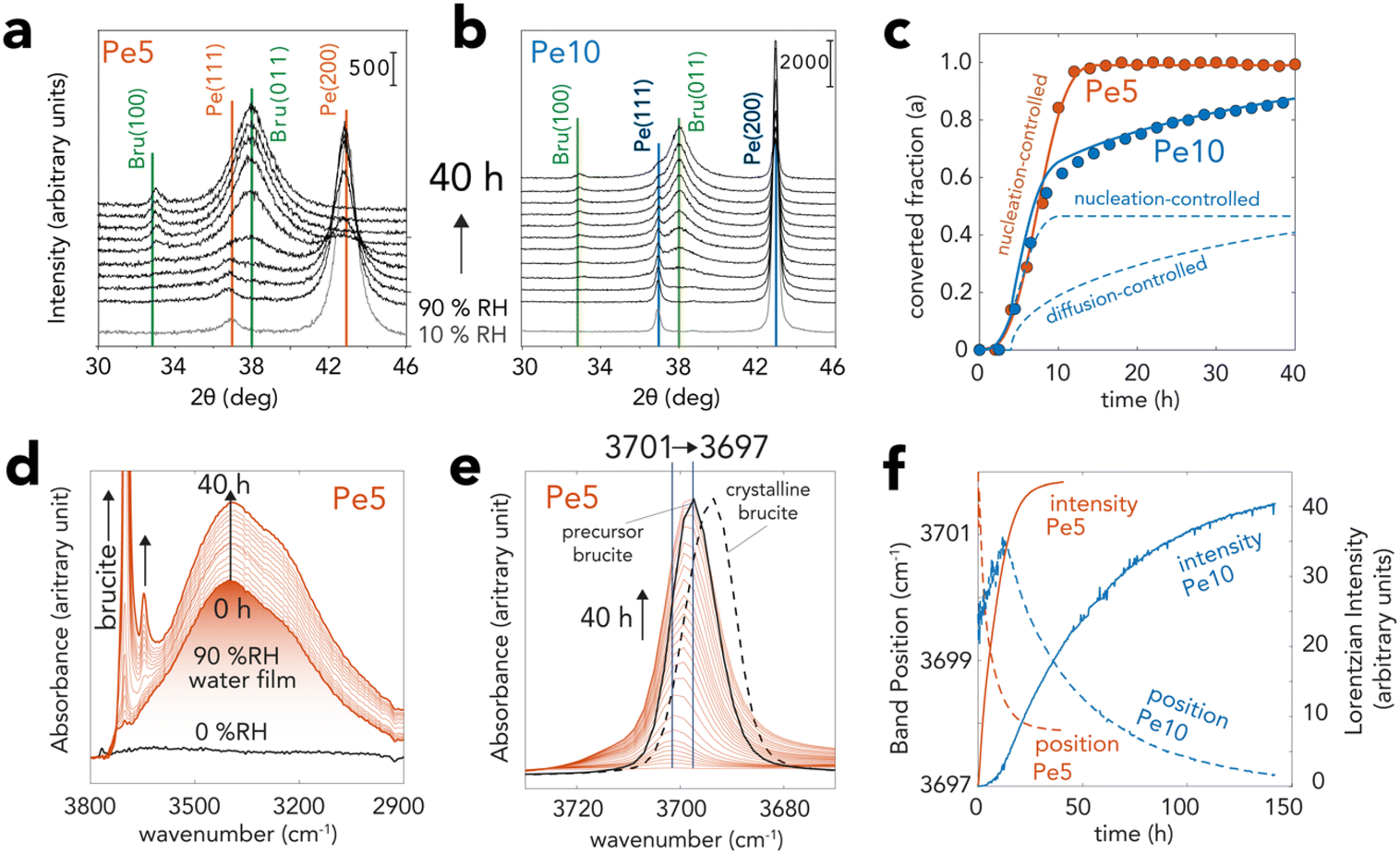 | ||
Fig. 3 XRD and vibrational spectroscopic evidence for brucite growth from periclase in nanometric water films. Pe5 and Pe10 samples were exposed to a flow of N2(g) with 90% RH at 25 °C over time. (a and b) Time-resolved X-ray diffractograms of (a) Pe5 and (b) Pe10 revealing the transformation of periclase (Fm![[3 with combining macron]](https://www.rsc.org/images/entities/char_0033_0304.gif) m space group) to brucite (Pm1 space group). (c) Converted fraction (α) of Pe5 and Pe10 resolved by Rietveld refinement of data in (a) and (b) over a 40 h reaction period. Curves were generated with the Avrami (nucleation-controlled) and Ginstling–Brounshtein (diffusion-controlled) models (ESI†). (d and e) Vibrational spectra of Pe5 during the reactions, revealing concomitant growth of brucite (two bands >3600 cm−1) and water films (∼3300 cm−1). (e) Background-corrected main band of brucite showing a progressive shift of the bulk O–H stretch from 3701 to 3697 cm−1. The black full line denotes spectrum synthetic brucite used to produce Pe5. The dashed line shows the spectrum of crystalline brucite. (f) Lorentzian fitting of the 3680–3720 cm−1 region of (e) for Pe5 (cf. Fig. S4d† for Pe10) showing comparable shapes of growth curves (intensity) as in (c) XRD as well as shifts in band position. Note that differences in sample preparation (loose MgO powders by XRD and solid MgO state films by vibrational spectroscopy) explain the contrasting reaction times between the two techniques. m space group) to brucite (Pm1 space group). (c) Converted fraction (α) of Pe5 and Pe10 resolved by Rietveld refinement of data in (a) and (b) over a 40 h reaction period. Curves were generated with the Avrami (nucleation-controlled) and Ginstling–Brounshtein (diffusion-controlled) models (ESI†). (d and e) Vibrational spectra of Pe5 during the reactions, revealing concomitant growth of brucite (two bands >3600 cm−1) and water films (∼3300 cm−1). (e) Background-corrected main band of brucite showing a progressive shift of the bulk O–H stretch from 3701 to 3697 cm−1. The black full line denotes spectrum synthetic brucite used to produce Pe5. The dashed line shows the spectrum of crystalline brucite. (f) Lorentzian fitting of the 3680–3720 cm−1 region of (e) for Pe5 (cf. Fig. S4d† for Pe10) showing comparable shapes of growth curves (intensity) as in (c) XRD as well as shifts in band position. Note that differences in sample preparation (loose MgO powders by XRD and solid MgO state films by vibrational spectroscopy) explain the contrasting reaction times between the two techniques. | ||
 | ||
| Fig. 4 Gravimetric tracking of periclase hydroxylation and dehydroxylation. (a) Microgravimetrically-measured water loadings by exposing water vapor from 0.9 to 92% RH at 10% RH intervals, each with a reaction time of 1 h. The right-hand side of (a) is a size-scaled schematic representation of the total equivalent water films thickness in relation periclase nanocube size. One water monolayer (ML) corresponds to 12 H2O per nm2. (b) Time-resolved water uptake at 95% RH by microgravimetry. Periclase was covered by a 3 ML-thick water film at the onset of the reaction. Water mass increases were driven by hydroxylation reactions and water film growth on newly formed brucite nanoparticles. Removal of water films by drying after 40 h revealed the reaction of 85% of Pe5 O groups and 75% of Pe10 O groups. (c) Thermogravimetric analysis (TGA) of brucite dehydroxylation after exposing Pe5 and Pe10 under 95% RH for 40 h. The full reconversion of Pe5-derived brucite (100% by XRD, Fig. 3c) showed that 15% of Pe5 was originally hydroxylated because (b) microgravimetry revealed 85% conversion. The 80% reconversion of Pe10-derived brucite (80% by XRD) (Fig. 3c) showed that 5% of Pe10 was originally hydroxylated because microgravimetry (b) revealed 75% conversion. Spectroscopic evidence for OH groups on Pe5 and Pe10 is provided in Fig. S5 and S6.† | ||
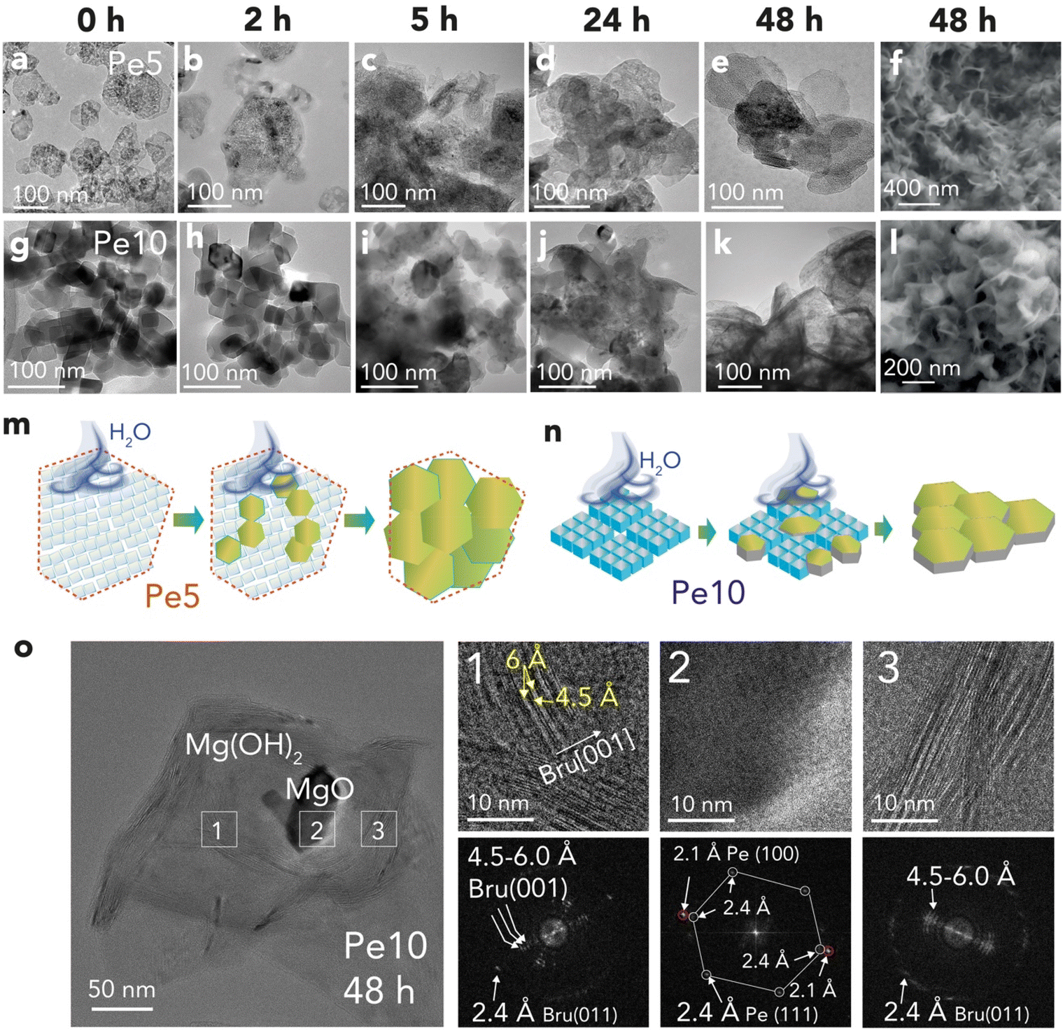 | ||
| Fig. 5 Imaging and schematic representation of periclase converted to brucite. Imaging of (a–f) Pe5 and (g–l) Pe10 reacted to 90% RH for up to 48 h by (a–e and g–k) TEM and (f and l) by SEM. (m and n) Schematic representations of (m) Pe5 nanocubes converting to brucite within the incipient casings in which they were clustered and (n) Pe10 expanding into brucite. (o) Cryogenic HTREM imaging of Pe10 reacted to 90% RH for 48 h, here showing an unreacted core (Region 2) embedded by brucite overgrowth (Regions 1 and 2). HRTEM of Regions 1–3 revealed lattice fringes of the corresponding minerals (2.1 Å for periclase (100), 2.4 Å for either brucite (011) or periclase (111)). A wider range of longer values for brucite (4.5–6.0 Å) likely arise from other, unresolved, types of interlayers in brucite booklets. | ||
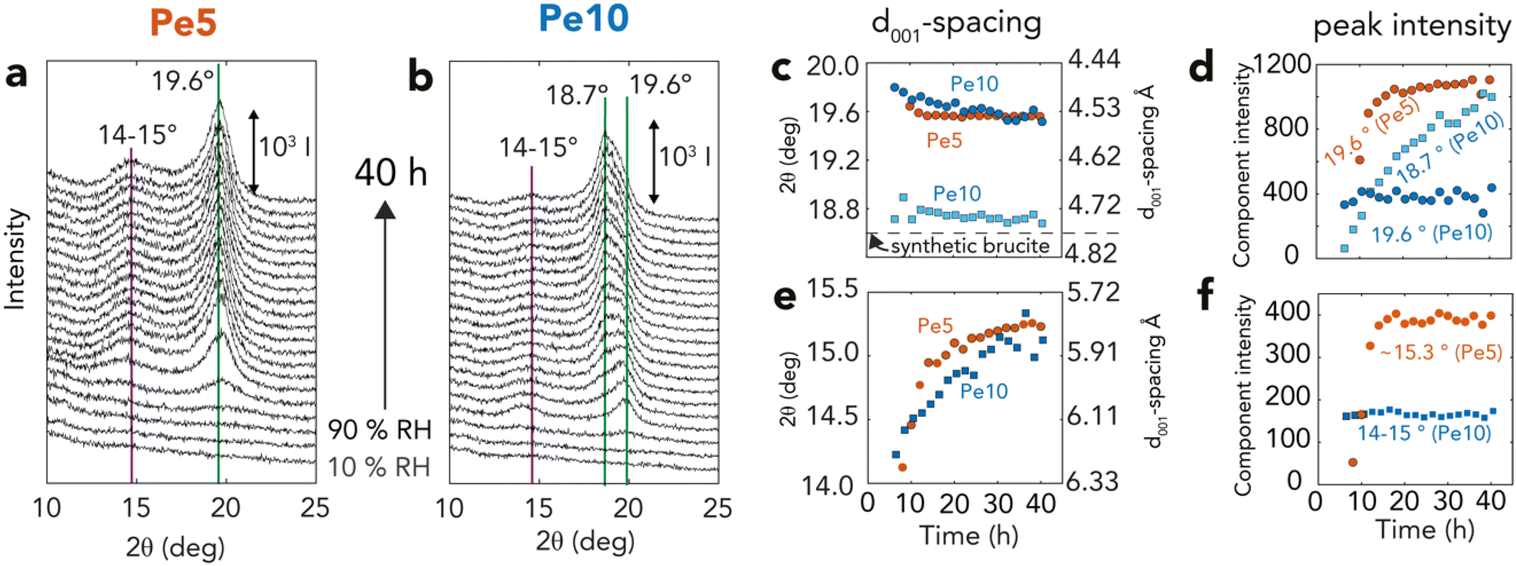 | ||
| Fig. 6 XRD (001) reflections of brucite over time (a and b) Brucite (001) reflections from time-resolved X-ray diffractograms of Fig. 3 for (a) Pe5 (orange) and (b) Pe10 (blue), highlighting dominant reflections appearing as periclase is exposed to 90% RH for 40 h. Lorentzian fitting parameters of all reflections (Fig. S7†) are shown as (c and e) peak position (2θ) and corresponding d001-spacing and (d and f) peak intensity. | ||
Brucite growth triggered by three monolayer-thick water films
XRD captured hydroxylation reactions through the progressive loss of the primary (200) and (111) reflections of periclase, and by the appearance of the (011) and (100) reflections of brucite (Fig. 3a–c). To quantify the progress of the conversion reactions, we analyzed these main reflections by Rietveld refinement57,58 (Fig. 3c). This analysis showed that the crystalline fractions of Pe5 and Pe10 reacted at identical rates in the first ∼8 h. Reactions in Pe10 however continued to progress at a slower rate than Pe5, reaching ∼85% conversion after 40 h. Pe5 was, on the other hand, fully converted only after ∼12 h of exposure to 90% RH.Vibrational spectroscopy captured the formation of bulk brucite OH groups through the growth of a O–H stretching band, first appearing at ∼3701 cm−1 (Fig. 3d and e). Time-resolved band intensities, obtained by Lorentzian fitting (Fig. 3f), showed that growth curves had comparable shapes to those obtained by XRD (Fig. 3c). The reactions were, however, slower because these measurements required MgO nanocubes in the form of packed thin solid-state films, rather than loose powders as in all other methods used for this work. From the progressive shift of this band to ∼3697 cm−1, we infer that brucite OH groups formed stronger intersheet hydrogen bonds over time. These bonds were, however, not fully established, because only thermal treatment (Fig. S4†) could shift the band to the characteristic vibrational frequency of crystalline brucite (3694 cm−1). This consequently indicated that brucite contained defects which, in the following sections, will be chiefly attributed to nanosheet dislocation.16,17
Microgravimetry (Fig. 4a) showed that periclase nanocubes exposed to 10–60%RH formed water films with steady coverages of up to 2 monolayers (MLs), at least within the first hour of reaction. Exposure to greater levels of humidity triggered, in contrast, an immediate and continuous uptake of water which signaled a rapid onset of the hydroxylation reactions. At 90%RH, reactions were triggered by ∼3 ML-thick films (Fig. 4b) and continued for up to 15 h for Pe5 and up to at least 40 h for Pe10 (Fig. 4b), in alignment with our Rietveld refinement results of the XRD data (Fig. 3c). We additionally find evidence that newly-formed brucite particles increased water film loadings over the course of the reaction. This was seen by microgravimetry through H2O![[thin space (1/6-em)]](https://www.rsc.org/images/entities/char_2009.gif) :MgO ratios exceeding the expected (1:1) reaction stoichiometry (Fig. 3b), and by vibrational spectroscopy (Fig. 3d and S4†) through the rise of the main water band (∼3300 cm−1).
:MgO ratios exceeding the expected (1:1) reaction stoichiometry (Fig. 3b), and by vibrational spectroscopy (Fig. 3d and S4†) through the rise of the main water band (∼3300 cm−1).
Drying the films off the reacted particles showed that H2O:MgO reaction ratios were of only ∼0.85 for Pe5 and ∼0.75 for Pe10 (Fig. 4b). These results thus contrasted with reaction yields obtained by XRD (Fig. 3c). To understand the implications of these results, we thermally decomposed the reaction products back to MgO using TGA (Fig. 4c). These experiments showed that dehydroxylation recovered 100% of the weight of Pe5 and ∼80% of the weight of Pe10. Because these results matched reaction yields obtained by Rietveld refinement (Fig. 3c), we conclude that unreacted Pe5 and Pe10 contained non-stoichiometric OH groups. This conclusion was supported further by vibrational (Fig. S4†) and X-ray photoelectron (Fig. S5†) spectroscopic measurements of the unreacted materials.
Nucleation- vs. diffusion-controlled brucite growth
To explain the contrasting time-dependent reaction yields of Pe5 and Pe10 (Fig. 3c and 4b, c), we modeled our Rietveld refinement results (Fig. 3c) with a hybrid kinetic growth model taken from the solid-state catalysis literature (cf. ESI† for full details on the model).44 We predicted the early stages of growth using a nucleation-limited model to account for competing ingestion and merging of nucleation sites in the water films. Later stages of growth were, on the other hand, predicted using a Shrinking Core Model54 to account for a diffusion-limited growth caused by the passivation of the reactive MgO core by brucite nanocoatings. Evidence for this passivating layer can also be appreciated by X-ray photoelectron spectroscopy (Table S2†). These results showed that Pe10 surfaces were entirely hydroxylated although XRD (Fig. 3a–c) indicated that the reactions were not completed. As such, we liken these assemblages to a biphasic MgO@Mg(OH)2 core–shell structure.The sinusoidal portions of Pe5 and Pe10 at the onset of the reactions were best described using a Avrami–Erofeyev52,53 model. This model ([−ln(1 − α)]1/3 = kAEt; where α = [0,1] is reaction progress and t reaction time) described growth in terms of the competing ingestion of nucleation sites and merging nuclei.44 It described the complete conversion (α = 0 → 1) for Pe5 and the partial conversion (α = 0 → 0.5) for Pe10 using a single growth constant (kAE = 6.6 h−1). To give additional perspective on this growth term in the context of water films, we note that a single Pe5 nanocube cannot completely dissolve into three monolayer-thick films (2.1 Mg2+ per H2O). The sustained rates of conversion must have therefore relied on the continual capture of water vapor by newly formed brucite nanoparticles. Again, evidence for this capture was detected by microgravimetry (Fig. 4b) and by vibrational spectroscopy (Fig. 3d and S4†).
The slower reactions in Pe10 after ∼4 h were predicted using a 3D Shrinking Core Model54 (Fig. 1). To this end, we used the Carter–Valensi59 adaptation of the Ginstling–Brounshtein model60 ( ; R is particle radius) to factor in the important volumetric expansion (
 ); v is molar volume) on the reaction rates (kVC). The model predicts that diffusion-limited growth (
 = 230 h−1 nm2) began after ∼4 h of reaction where ∼15% (α = 0.15) of the Pe10 transformed to brucite by nucleation-limited growth. We note that this level of conversion amounts to the consumption of the topmost ∼0.9 nm of the Pe10 surface, namely the equivalent of ∼5000 nm3 of MgO. As this volume corresponds to about ten Pe5 nanocubes, we conclude that Pe5 was completely converted to brucite under the nucleation-limited regime. This also implies that brucite nanocoatings formed on Pe5 were insufficiently thick to hamper the flux of reactive species to brucite growth fronts.
Morphological changes and co-existing phases
To identify morphological changes undergone by the nanoparticles, we imaged reacted samples using electron microscopy (Fig. 5a–l). Inspection of the larger Pe10 nanocubes provided insight into the earliest stages of the dissolution reactions (Fig. 5g–i). These images revealed a progressive increase in nanocube roundness. This aligns with previous work33,46,61 underscoring the thermodynamic drive for the conversion of the dominant (100) face to the (110) and (111) faces under hydration.18,21,62,63 These results thus support the idea that a preferential dissolution of the most reactive sites (e.g. nanocube corners and edges) triggered fluxes of Mg2+ ions in the water film, inducing the first events of brucite nucleation and growth. It is even possible that these new faces, alongside related defects, became nucleation sites for hydroxylation reactions, or even entry zones for water diffusion into the periclase bulk.Imaging of samples reacted over a period of 48 h revealed a progressive conversion of periclase nanocubes to brucite nanoflakes (Fig. 5f and l). Brucite growth from Pe5 nanocubes (Fig. 5a–f) was chiefly limited to the confines of the embedding hexagonal particles. Growth thereby occurred within the microporous interstices of aggregated Pe5 nanocubes/nanobars, as illustrated in Fig. 5m. In contrast, growth from Pe10 extended well beyond the sizes of the original nanocubes (Fig. 5g–l). This implies that a network of water films secured the flux of soluble Mg2+ species from different periclase particles to brucite growth fronts, such as represented in Fig. 5n.
Finally, to directly identify mineralogical phases by imaging, we turned to High-Resolution TEM (HRTEM). Cryogenic conditions minimized risks for electron beam damage.55 Imaging of reacted Pe10 (Fig. 5o) revealed spatially resolved lattice fringes from co-existing periclase (Region 2) and brucite (Regions 1) particles. Both Regions 1 and 3 contained a range of lattice fringes (4.5–6.0 Å) with the lowest value close to the expected d001-spacing value of brucite. In contrast, the larger values indicated that brucite contained various configurations of interstratified nanosheets. These findings consequently align with our vibrational spectra (Fig. 3e, f and S4†), and with previous imaging work,16,17 revealing weak intralayer bonding in dislocated brucite nanosheets. In the following section, we establish a link between these lattice fringes and our XRD measurements.
Contrasting nanosheet stacking
Variations in brucite nanosheet stacking were resolved by Lorentzian modeling of the main (001) reflection of brucite at 18.7–19.6° 2θ (Fig. 6a, b and S6, S7†). Applying Bragg's law (2d001 sin θ = n × λ, given n = 1 and λ = 1.54 Å) to calculate interlayer d001-spacing (Fig. 6c), we found that brucite produced from Pe5 had typically smaller interlayer d001-spacing values (∼19.6° 2θ, d001 = 4.59 Å) than in synthetic brucite (∼18.6° 2θ, d001 = 4.82 Å). This reflection was composed of a single component, and first appeared after ∼8 h, namely only near the end of the reaction (Fig. 3d). It then grew in tandem with other main brucite reflections (Fig. S7†) up to the ∼20th h of reaction (Fig. 6d). Pe10 also developed the same reflection after ∼7 h (∼19.8° 2θ, d001 = 4.54 Å), yet this component remained of fixed intensity for the remaining course of the reaction. Here, it was rather a second coexisting peak of crystalline brucite (18.7° 2θ, d001 = 4.80 Å) that grew in tandem with the other main brucite reflections (Fig. S7†).These two peaks also grew in parallel with another set of reflections at 14–15° 2θ (Fig. 6e and f). These reflections indicate d001-spacing values in the 5.91–6.33 Å range, and therefore correspond with lattice fringes seen by cryogenic HRTEM (Fig. 5o). Shifts in peak position over reaction time also revealed that these spacing values shrank (6.27 → 5.82 Å) as spacing values from the main (001) reflection expanded (4.48 → 4.53 Å). As these spacings were not sufficiently large to accommodate intercalated water (d001 + 2rH2O = 4.82 Å + 2.80 Å = 7.62 Å; where rH2O is the radius of a water molecule), we conclude that the 14–15° 2θ reflections arose from unresolved interstratified layers, and that these dynamically changed during the course of the reactions. Transient mixed oxyhydroxide (Mgx+yOx(OH)2y) intermediates, formed by water diffusion into the periclase bulk,17 could have also partially contributed to these results.
We can explain the uncharacteristically low d001-spacing values if high crystallization pressures were achieved during the reactions. This idea was already conveyed by Feitknecht and Braun32 who, in the 1960s, assigned a similar value (4.578 Å) to brucite grown under comparable conditions. Referring to pressure-resolved d001-spacing values64,65 published decades after that study, we infer crystallization pressures of ∼4 GPa could have been achieved during brucite growth.
This interpretation aligns with thermodynamic predictions12,25 for GPa-level crystallization pressures, and with our observation that removing the water film (Fig. S8†) shifted d001-spacings of reacted materials to low-pressure values. Whereas previous studies12,25 did show that reactions in compacted materials can stop at MPa-level pressures because water films are squeezed from the intergrain boundary, we can explain our findings the inherently large (26 μL g−1) microporosity of Pe5 nanocubes (Fig. 2b and c) sustained GPa-level pressures by retaining the network of water films. This was also the case for a minor portion of Pe10, which could be explained in terms of surface microporosity. These results consequently highlight the singular ability of synthetic periclase nanocubes, especially those of Pe5 aggregated in a 2D maze-like microporous network, to host high pressure reactions.
Conclusions
Two types of partially hydroxylated periclase nanocubes of contrasting size and microporosity provided an opportunity to explore the water film-driven nucleation- and diffusion-limited transformations to brucite nanosheets. Growth was triggered by three monolayer-thick water films, and autocatalyzed as water films grew onto newly formed brucite nanosheets. Nucleation-limited reactions initiated brucite growth, and completely converted (8 nm-wide) Pe5 nanocubes. Reactions however transitioned to a diffusion-limited growth regime in the larger (32 nm-wide) Pe10 nanocubes. Establishement of a biphasic MgO@Mg(OH)2 core–shell structure hampered the flux of species to growth fronts. Additionally, the microporous network between aggregated Pe5 nanocubes and pores at Pe10 surfaces hosted GPa-level crystallization pressures that compressed brucite interlayer spacings during growth. These interlayer spacings however expanded back to ambient pressure values once water films were removed.By resolving brucite growth in terms of concurrent nucleation- and diffusion-limited regimes, our work unveiled important differences caused by nanoparticle formation history on the composition and structure of reaction products. Because water films are important drivers of mineral alteration in nature and technology, consideration of these findings will be needed in studying nanomineral transformations in areas including atmospheric chemistry, catalysis, electrochemistry, geochemistry, and surface science. Considerations of these findings can even apply to broader aspects of material alteration and crystal growth by nanometric water films. This includes structurally-related materials (e.g., CaO, FeO) as well as, more generally, transformations under nanoconfinement (e.g., nanopores) in minerals (e.g., clays, zeolites) or other materials of technological interest (e.g., metal–organic frameworks, carbon nanotubes).
Data availability
All supporting data is provided in the ESL.Author contributions
TL, MH, and JFB: conceived experiments and manuscript writing. TL: all synthetic work and experiments, and Rietveld and Lorentzian analyses of XRD data. JFB: numerical analyses of vibrational spectra and kinetic modeling of Rietveld refinements of XRD data.Conflicts of interest
There are no conflicts of interest to declare.Acknowledgements
This research was supported by Vetenskapsrådet (Swedish Research Council, VR-2020-05853) and Svenska Forskningsrådet för miljö, areella näringar och samhällsbyggande (Formas, 2022-01246) to J.-F. B. The authors acknowledge the facilities and technical assistance of Cheng Choo Lee of the Umeå Core Facility Electron Microscopy (UCEM; Cheng Choo) and of Andrey Shchukarev of the X-ray photoelectron spectroscopy platform at the Chemical Biological Centre (KBC), Umeå University. The authors also thank Hussein Kanbar for assistance with X-ray diffraction work.References
- J. Hu, X.-D. Xiao, D. F. Ogletree and M. Salmeron, Science, 1995, 268, 267–269 CrossRef CAS PubMed.
- G. E. Ewing, Chem. Rev., 2006, 106, 1511–1526 CrossRef CAS PubMed.
- G. R. Bourret and O. Diwald, J. Mater. Res., 2019, 34, 428–441 CrossRef CAS.
- L. R. Merte, R. Bechstein, G. Peng, F. Rieboldt, C. A. Farberow, H. Zeuthen, J. Knudsen, E. Lægsgaard, S. Wendt, M. Mavrikakis and F. Besenbacher, Nat. Commun., 2014, 5, 4193 CrossRef CAS PubMed.
- S. E. Yalcin, B. A. Legg, M. Yeşilbaş, N. S. Malvankar and J.-F. Boily, Sci. Adv., 2020, 6, eaaz9708 CrossRef CAS PubMed.
- D. Thomele, A. R. Gheisi, M. Niedermaier, M. S. Elsasser, J. Bernardi, H. Gronbeck and O. Diwald, J. Am. Ceram. Soc., 2018, 101, 4994–5003 CrossRef CAS PubMed.
- N. T. Luong, E. S. Ilton, A. Shchukarev and J.-F. Boily, Geochim. Cosmochim. Acta, 2022, 329, 87–105 CrossRef.
- M. A. Henderson, Surf. Sci. Rep., 2002, 46, 1–308 CrossRef CAS.
- G. Rubasinghege and V. H. Grassian, Chem. Commun., 2013, 49, 3071–3094 RSC.
- M. Tang, D. J. Cziczo and V. H. Grassian, Chem. Rev., 2016, 116, 4205–4259 CrossRef CAS PubMed.
- M. Kim and D. Or, Nat. Commun., 2019, 10, 3944 CrossRef PubMed.
- M. G. Guren, H. A. Sveinsson, A. Hafreager, B. Jamtveit, A. Malthe-Sørenssen and F. Renard, Geochim. Cosmochim. Acta, 2021, 294, 13–27 CrossRef CAS.
- S. N. Kerisit and J. J. De Yoreo, J. Phys. Chem. C, 2020, 124, 5480–5488 CrossRef CAS.
- T. A. Ho, D. V. Papavassiliou, L. L. Lee and A. Striolo, Proc. Natl. Acad. Sci. U. S. A., 2011, 108, 16170–16175 CrossRef CAS PubMed.
- S. Hayun, T. Tran, S. V. Ushakov, A. M. Thron, K. van Benthem, A. Navrotsky and R. H. R. Castro, J. Phys. Chem. C, 2011, 115, 23929–23935 CrossRef CAS.
- R. Sharma, M. J. McKelvy, H. Béarat, A. V. G. Chizmeshya and R. W. Carpenter, Philos. Mag., 2004, 84, 2711–2729 CrossRef CAS.
- M. J. McKelvy, R. Sharma, A. V. G. Chizmeshya, R. W. Carpenter and K. Streib, Chem. Mater., 2001, 13, 921–926 CrossRef CAS.
- C. Chizallet, G. Costentin, M. Che, F. Delbecq and P. Sautet, J. Am. Chem. Soc., 2007, 129, 6442–6452 CrossRef CAS PubMed.
- S. Coluccia, S. Lavagnino and L. Marchese, Mater. Chem. Phys., 1988, 18, 445–464 CrossRef CAS.
- J. T. Newberg, D. E. Starr, S. Yamamoto, S. Kaya, T. Kendelewicz, E. R. Mysak, S. Porsgaard, M. B. Salmeron, G. E. Brown, A. Nilsson and H. Bluhm, Surf. Sci., 2011, 605, 89–94 CrossRef CAS.
- E. Knözinger, K.-H. Jacob, S. Singh and P. Hofmann, Surf. Sci., 1993, 290, 388–402 CrossRef.
- J. A. Mejias, A. J. Berry, K. Refson and D. G. Fraser, Chem. Phys. Lett., 1999, 314, 558–563 CrossRef CAS.
- P. Liu, T. Kendelewicz, G. E. Gordon and G. A. Parks, Surf. Sci., 1998, 412–13, 287–314 CrossRef.
- N. M. Adhikari, A. Tuladhar, Z. Wang, J. J. De Yoreo and K. M. Rosso, J. Phys. Chem. C, 2021, 125, 26132–26138 CrossRef CAS.
- X. J. Zheng, B. Cordonnier, W. L. Zhu, F. Renard and B. Jamtveit, Geochem., Geophys., Geosyst., 2018, 19, 2661–2672 CrossRef CAS.
- S. A. Walling and J. L. Provis, Chem. Rev., 2016, 116, 4170–4204 CrossRef CAS PubMed.
- T. Santos, A. P. Luz, C. Pagliosa and V. C. Pandolfelli, J. Am. Ceram. Soc., 2016, 99, 461–469 CrossRef CAS.
- G. K. Layden and G. W. Brindley, J. Am. Ceram. Soc., 1963, 46, 518–522 CrossRef CAS.
- W. F. Giauque, J. Am. Chem. Soc., 1949, 71, 3192–3194 CrossRef CAS.
- R. I. Razouk and R. S. Mikhail, J. Phys. Chem., 1958, 62, 920–925 CrossRef CAS.
- H. Naono, Colloids Surf., 1989, 37, 55–70 CrossRef.
- W. Feitknecht and H. Braun, Helv. Chim. Acta, 1967, 50, 2040–2053 CrossRef CAS.
- S. O. Baumann, J. Schneider, A. Sternig, D. Thomele, S. Stankic, T. Berger, H. Gronbeck and O. Diwald, Langmuir, 2015, 31, 2770–2776 CrossRef CAS PubMed.
- V. S. S. Birchal, S. D. F. Rocha and V. S. T. Ciminelli, Miner. Eng., 2000, 13, 1629–1633 CrossRef CAS.
- M. A. Shand, The Chemistry and Technology of Magnesia, Wiley, 2006 Search PubMed.
- C. A. Gärtner, A. C. van Veen and J. A. Lercher, ChemCatChem, 2013, 5, 3196–3217 CrossRef.
- A. L. Harrison, G. M. Dipple, I. M. Power and K. U. Mayer, Geochim. Cosmochim. Acta, 2015, 148, 477–495 CrossRef CAS.
- M. Chen and D. A. Dixon, J. Phys. Chem. C, 2017, 121, 21750–21762 CrossRef CAS.
- H.-J. Shin, J. Jung, K. Motobayashi, S. Yanagisawa, Y. Morikawa, Y. Kim and M. Kawai, Nat. Mater., 2010, 9, 442–447 CrossRef CAS PubMed.
- R. A. Wogelius, K. Refson, D. G. Fraser, G. W. Grime and J. P. Goff, Geochim. Cosmochim. Acta, 1995, 59, 1875–1881 CrossRef CAS.
- L. F. Amaral, I. R. Oliveira, R. Salomão, E. Frollini and V. C. Pandolfelli, Ceram. Int., 2010, 36, 1047–1054 CrossRef CAS.
- D. Thomele, G. R. Bourret, J. Bernardi, M. Bockstedte and O. Diwald, Angew. Chem., Int. Ed., 2017, 56, 1407–1410 CrossRef CAS PubMed.
- D. Thomele, S. O. Baumann, J. Schneider, A. K. Sternig, S. Shulda, R. M. Richards, T. Schwab, G. A. Zickler, G. R. Bourret and O. Diwald, Cryst. Growth Des., 2021, 21, 4674–4682 CrossRef CAS PubMed.
- A. Khawam and D. R. Flanagan, J. Phys. Chem. B, 2006, 110, 17315–17328 CrossRef CAS PubMed.
- S. Yagi and D. Kunii, Chem. Eng. Sci., 1961, 16, 372–379 CrossRef CAS.
- R. Schwaiger, J. Schneider, G. R. Bourret and O. Diwald, Beilstein J. Nanotechnol., 2016, 7, 302–309 CrossRef CAS PubMed.
- M. Foster, M. Dagostino and D. Passno, Surf. Sci., 2005, 590, 31–41 CrossRef CAS.
- T. Taut, R. Kleeberg and J. Bergmann, Materials Science (Bulletin of the Czech and Slovak Crystallographic Association), 1998, vol. 5, pp. 55–64 Search PubMed.
- R. T. Downs and M. Hall-Wallace, Am. Mineral., 2003, 88, 247–250 CrossRef CAS.
- R. M. Hazen, Am. Mineral., 1976, 61, 266–271 CAS.
- M. Catti, G. Ferraris, S. Hull and A. Pavese, Phys. Chem. Miner., 1995, 22, 200–206 CrossRef CAS.
- M. Avrami, J. Chem. Phys., 1939, 7, 1103–1112 CrossRef CAS.
- B. V. Erofeyev, Dokl. Akad. Nauk Ukr. SSR, 1946, 52, 511–514 Search PubMed.
- S. Yagi and D. Kunii, Chem. Eng. Sci., 1961, 16, 380–391 CrossRef CAS.
- P. A. V. Aken and F. Langenhorst, Eur. J. Mineral., 2001, 13, 329–341 CrossRef.
- M. G. Kim, U. Dahmen and A. W. Searcy, J. Am. Ceram. Soc., 1987, 70, 146–154 CrossRef CAS.
- H. Rietveld, Acta Crystallogr., 1967, 22, 151–152 CrossRef CAS.
- R. A. Young, The Rietveld Method, Oxford Science Publications, 1993 Search PubMed.
- R. E. Carter, J. Chem. Phys., 1961, 34, 2010–2015 CrossRef CAS.
- A. M. Ginstling and V. I. Brounshtein, J. Appl. Chem. USSR, 1950, 23, 1327–1338 CAS.
- M. Gajdardziska-Josifovska, R. Plass, M. A. Schofield, D. R. Giese and R. Sharma, J. Electron Microsc., 2002, 51, S13–S25 CrossRef.
- C. A. Scamehorn, N. M. Harrison and M. I. McCarthy, J. Chem. Phys., 1994, 101, 1547–1554 CrossRef CAS.
- O. Diwald, M. Sterrer and E. Knozinger, Phys. Chem. Chem. Phys., 2002, 4, 2811–2817 RSC.
- K. Shinoda and N. Aikawa, Phys. Chem. Miner., 1998, 25, 197–202 CrossRef CAS.
- M. Ma, W. Liu, Z.-Q. Chen, Z. Liu and B. Li, Am. Mineral., 2013, 98, 33–40 CrossRef CAS.
Footnote |
| † Electronic supplementary information (ESI) available. See DOI: https://doi.org/10.1039/d2nr07140a |
| This journal is © The Royal Society of Chemistry 2023 |