Open-circuit voltage loss in perovskite quantum dot solar cells

Zijin Ding a, Saisai Li a, Yuanzhi Jiang a, Di Wang a and Mingjian Yuan *ab
aKey Laboratory of Advanced Energy Materials Chemistry (Ministry of Education), Renewable Energy Conversion and Storage Center (RECAST), College of Chemistry, Nankai University, Tianjin, 300071, P. R. China
bHaihe Laboratory of Sustainable Chemical Transformations, Tianjin, 300071, P. R. China. E-mail: yuanmj@nankai.edu.cn

Received 13th December 2022 , Accepted 16th January 2023

First published on 16th January 2023


Abstract

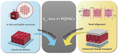
Perovskite quantum dots are a competitive candidate for next-generation solar cells owing to their superior phase stability and multiple exciton generation effects. However, given the voltage loss in perovskite quantum dot solar cells (PQDSCs) is mainly caused by various surface and interfacial defects and the energy band mismatch in the devices, tremendous achievements have been made to mitigate the Voc loss of PQDSCs. Herein, we elucidate the potential threats that hinder the high Voc of PQDSCs. Then, we summarize recent progress in minimizing open-circuit voltage (Voc) loss, including defect manipulation and device optimization, based on band-alignment engineering. Finally, we attempt to shed light on the methodologies used to further improve the performance of PQDSCs.

1 Introduction

Metal halide perovskites have drawn significant attention owing to their application in photovoltaic technologies, accompanied by a rapid increase in PCE from 3.8% to 25.7%.1–5 Despite the stunning performance of perovskite solar cells, the notorious stability issues of bulk perovskites against temperature, humidity, and illumination are potential constraints that impede the further development of perovskite solar cells.7–10 Perovskite quantum dots could be the ready solution to this dilemma. By leveraging the surface energy of quantum dots, the intrinsic stability of perovskites can be enhanced.13–15 To date, the synthesis process is well-established to obtain high-quality perovskite quantum dots owing to the broad chemical diversity of the solvent system and capping ligands.17–22 The combination of the peculiar synthetic method and layer-by-layer deposition decoupled the complicated crystallization kinetics from the deposition on the substrate and further pushed the PQDs toward application in solar cells.27 In 2016, Luther et al. successfully harnessed the potential of perovskite quantum dots and, for the first time, reported the perovskite quantum dot solar cells (PQDSCs) with PCE exceeding 10%.13 This study paved a new avenue for the perovskite solar cell and drew significant attention to the PQDSCs in the following years.24,26,36–39

The theoretical efficiency, based on Shockley–Queisser, is about 32% for a single-junction perovskite solar cell with a bandgap of 1.5 eV.43 Despite the widened bandgap for the size confinement effect and the high PLQY of PQDs, there is still an untapped opportunity to reduce the Voc loss and improve the performance of PQDSCs. Owing to the complexity of the synthesis and post-treatment process, perovskite quantum dots usually have various surface defects, even the remnant of reactants, which possibly facilitate non-radiative recombination and cause voltage deficit.16,45,46 In particular, the unclear surface chemistry, charge carrier dynamics, and inter-dot coupling make it more difficult to enhance charge carrier hopping between the dots. Moreover, a widely discussed interfacial recombination and energy level arrangement perplex the issue of Voc loss.48–52 Because of the excessive grain boundaries and interfaces introduced by layer-by-layer deposition, the PQD film inevitably contains many defects, intensifying non-radiative recombination. In addition, the unique surface properties increase the difficulty of manipulating the contact at the CTL/perovskite interface, thus causing severe degradation and deterioration of the charge transport at the interface.47,53

Considering the performance development of perovskite quantum dot solar cells, a significant amount of work is required to minimize the Voc loss and boost the PCE towards the Shockley–Queisser limit. The aforementioned issues urgently need solutions to reduce the Voc loss of PQDSCs, while a systematic review of the timely approaches to minimize the Voc loss in PQDSCs is still lacking. In this review, we discuss representative studies on reducing the Voc loss of a wide span of perovskite quantum dots with different compositions and bandgaps. We briefly introduce the theoretical background of detailed balance theory and the possible inducement of radiative recombination and non-radiative recombination loss. After that, we investigate the defect manipulation strategies of PQDs based on synthesis optimization and surface treatment. A series of studies on surface engineering is reviewed. We attempt to give instructions on screening the appropriate capping ligands and purification solvents to reduce the non-radiative recombination of the PQDs. In Section 4, we emphasize interfacial modification and band alignment to boost charge carrier transport and reduce interfacial recombination. Some judicious approaches, including homojunction and heterojunction construction and charge transport material design, are summarized to minimize the Voc loss. Finally, we raise some feasible methods to minimize the Voc loss and anticipate the developed performance and further application for PQDSCs.

2 Voltage loss in PQDSCs

2.1 The mechanism of open-circuit voltage loss

The Voc loss of perovskite quantum dot solar cells can be estimated based on detailed balance theory. In particular, the discrepancy between the bandgap and output Voc in a real PSC comprises 3 parts (Fig. 1): (1) the difference between the S–Q limit and the bandgap (ΔE1); (2) the radiative voltage loss (ΔE2/q), including ΔVoc, SC (short-circuit loss term caused by the difference between Jsc and JSQsc) and ΔVoc, rad; and (3) the non-radiative recombination caused voltage loss (ΔE3).57–59,62 We have
 
image file: d2nr06976h-t1.tif(1)

image file: d2nr06976h-f1.tif
Fig. 1 Schematic illustration of the voltage loss in a practical solar cell.

According to the optoelectronic reciprocity theorem, ΔE1 is assumed to be the energy difference between the bandgap and the S–Q limit Voc caused by the isothermal losses and optical entropy generation.60 This part of energy loss is usually in the range of 0.25–0.30 eV for a solar cell with an appropriate bandgap.61 ΔE1 can be expressed as a function of bandgap and temperature:

 
image file: d2nr06976h-t2.tif(2)
where ΦAM1.5G denotes the solar radiation spectrum with an air mass of 1.5 and ΦBB for the black body radiation. This part of voltage loss is inevitable in all kinds of solar cells.

ΔE2 originates from the energy difference between the photoluminescent emission and the bandgap. The bandgap is regarded as a step function in S–Q theory, and the absorption of a practical solar cell is usually a function of the photon energy.46 Hence, the EQEPV is introduced to correct the expression for the ΔE2, which indicates the ratio of the photons that generate the electric current of a solar cell held under short circuit conditions. ΔE2 is calculated using the following equation:

 
image file: d2nr06976h-t3.tif(3)
where ΔE3 represents the non-radiative recombination loss, which is related to the defects in the practical solar cell. This part of the voltage loss is avoidable by optimizing the crystallinity of the light absorber and device structure. By ulteriorly plugging in EQEEL, ΔE3 is defined by the following equation:
 
ΔE3 = −kBT·ln[thin space (1/6-em)]EQEEL(4)
 
image file: d2nr06976h-t4.tif(5)
where EQEEL denotes the electroluminescence external quantum efficiency.

To directly quantify radiative loss (ΔE2) and non-radiative loss (ΔE3), several electrical, electro-optical, and optical methods have been developed to examine the origin of Voc loss. As aforementioned, when a solar cell is on its radiative limit, the radiative limit dark saturation current (J0, rad) can be calculated based on the optoelectronic reciprocity theory:

 
image file: d2nr06976h-t5.tif(6)

We can simply conclude from eqn (6) that the external quantum efficiency of a solar cell allows the determination of the radiative limit current, further the Voc, rad and ΔE2. In a real solar cell, non-radiative loss comprises bulk recombination and surface recombination. The absolute PL is employed to disentangle these two kinds of energy loss, herein defined as ΔVoc, BNR and ΔVoc, SR. ΔVoc, BNR is usually regarded as the voltage loss caused by intrinsic defects that are usually electronically active and act as bulk recombination centers.38 After the assembling of solar cells, the energetics and interfacial defects introduced by the contacts trigger the ΔVoc, SR. Under working conditions, electrons are excited from the valence band to the conduction band under irradiation, resulting in the redistribution of charge carriers. The Fermi level splits into the Fermi level of electrons (EFn) and holes (EFp). The ΔVoc, SR is defined as the difference of quasi-Fermi level splitting (ΔEF = EFnEFp) of perovskite before (ΔEF, bulk) and after contacts (ΔEF, contacts), which is expressed in the following equation:

 
ΔVoc,SR = ΔEF, bulk − ΔEF, contacts = ΔEF, bulkqVoc(7)

In recent discussions, μbulk is quantified by the absolute photoluminescence spectra according to Würfel's generalized Planck's law:111

 
image file: d2nr06976h-t6.tif(8)
where a(E) denotes the absorptivity related to photon energy E; with an assumption that the absorptivity of photons with energy above the PL maximum is regarded as unity, eqn (7) can be reduced to the following equation:
 
image file: d2nr06976h-t7.tif(9)

After the above derivation (eqn (8) and (9)), the ΔEF, bulk and ΔEF, contacts can be deduced from the intercept by linear fitting of the high energy slope of PL spectra.112

After analyzing the step-by-step energy loss in the photoconversion process, we set up a holistic comprehension of the Voc loss. In the next subsection, we discuss the specific voltage loss in a practical PQDSC, which we define as (Voc, radVoc).

2.2 Non-radiative recombination in PQDSCs

The detailed balance theory demonstrates that in PQDSCs, the non-radiative recombination triggered by the defect in the whole device and the energy level mismatch of different layers are the two main reasons that cause the Voc loss. Despite the high defect tolerance and colloidal integrity of perovskite quantum dots, various issues arise in photovoltaic devices.63 Owing to the peculiar synthesis method, cyclic purification, and deposition process, the surface ligands of PQDs are peeled off and cause some surface defects, which usually act as recombination channels.46,64–66 The residual reactants serve as defects stemming from quantum dots. All latent defects can cause severe voltage loss in PQDSCs. To solve these problems, a more judicious synthesis protocol must be adopted. Moreover, capping ligands are another crucial element used in determining the quality of PQDs. Through delicate molecular design with multiple criteria, such as the ligand chemical hindrance and functional groups, the detachment and bond of the ligands could finally come to a dynamic equilibrium.22,42,67,68 The ligand-exchange process on the as-deposited film is another factor that must be considered. A polar solvent is always employed as the ligand-removal agent without sacrificing the structural and phase stability of the quantum dots.26,41 It is challenging to find appropriate anti-solvents that are the best of both worlds.

Apart from the voltage loss originating from the light absorber, interface recombination is almost a universal problem for all perovskite solar cells, which is usually caused by energy level mismatch and interfacial defects.24,29,48,69 Generally, the unfavoured band structure between the light absorber and charge transport layers would cause insufficient charge transfer and block, thus generating charge carrier recombination at the interfaces. The ill-suited energy levels and large energy offset would trigger band bending, thus narrowing the quasi-Fermi level splitting and lowering the Voc. Although several strategies and efforts have been made to optimize the fabrication of PQDs, there is still room to reduce the voltage loss in PQDSCs based on the whole device level. In Fig. 2a–c, we compared the open-circuit voltage of the reported efficient PQDSCs and their counterparts in bulk PSCs against the Shockley–Queisser limit. It is shown that the A-site alloyed Cs0.25FA0.75PbI3 QDs possess the smallest Voc loss similar to the corresponding bulk perovskite solar cell with a similar bandgap, while others still suffer from a severe Voc loss.38 Throughout the developing history of the PSCs, it is evident that Voc is regarded as the most challenging to improve. Because the fill factor (FF) highly depends on non-radiative recombination and interfacial contact, a decent Voc guarantees high FF and good efficiency. Since Luther et al. first reported PQDSCs with efficiency exceeding 10%, to date, great efforts have been devoted to elevating the performance of the PQDSCs. A significant reduction in Voc loss is achieved by multiple strategies, including but not limited to, optimizing the synthesis protocol, post-treatment, and device structure, which are discussed in the following sections.


image file: d2nr06976h-f2.tif
Fig. 2 (a) Comparison of open-circuit voltage versus bandgap of PQDSCs and their counterpart of bulk PSCs. Schematic illustration of (b) voltage loss with respect to the bandgap for bulk PSCs and (c) voltage loss with respect to bandgap for PQDSCs. The plots are based on the data listed in Table 1.2–4,70–76

3 Defect management of PQDs

The colloidal perovskite quantum dots are intrinsically defect-tolerant and always feature near-unity PLQY. However, after cyclic purification and layer-by-layer deposition process, multiple defects surely emerge that deteriorate the optoelectronic properties and cause Voc loss. Hence, it is clear that the perfection of the synthesis protocol, ligand engineering, and post-treatment are prominent in rationalizing the surface defects of the QDs. Significant approaches to surface chemistry are summarized in the following subsection.

3.1 Synthesis protocol of perovskite quantum dots

The structural nature of QDs with a perovskite core wrapped in a ligand shell is important for studying capping ligands and surface properties. The capping ligands act as stabilizing surfactants and dominate the reaction path and the quality of the QDs. According to covalent bond classification theory, the extensive surface ligand database can be divided into X-type, L-type, and A-type categories.65,77 X-type ligands are identified as one-electron donors that either interact with halide anion or Pb2+ and Cs+ cations, and zwitterionic molecules, which interact with both. L-type ligands are two-electron donors that provide a lone pair of electrons for Pb2+; z-type ligands are two-electron acceptors that accept a lone pair of electrons from the halide anions. The adhesion and functional groups varied from ligand to ligand, thus passivating various surface defects.

When we investigate the entire reaction of the synthesis process, the chemical equilibrium of the nucleation and growth stages significantly affects the properties. Qian et al. introduced a ternary precursor system and elucidated the relationship between the Pb/I ratios and QD optoelectronic properties (Fig. 3a).6 After increasing the iodide input, the authors effectively dulled the iodide vacancies and achieved a champion Voc of 1.248 V and a PCE of 13.12%. Chen et al. put forward a chemical stripping treatment, thus improving the orientation of PQD after being deposited into a solid film and suppressing the intrinsic defect of the PQDs, as shown in Fig. 3b.28 By judiciously optimizing the surface chemistry of the PQDs, the charge carrier transport is improved from dot-to-dot, and the charge carrier non-radiative recombination is inhibited. Considering the further post-synthesis process, the widely used OA/OLA ligands pair suffer from severe detachment. Based on the termination by CsX, PbX2, and AX, the perovskite quantum dots are divided into three structural models, as shown in Fig. 3c and d.42 The surface motif reveals a loose bind between the ammonium and bromide anions. The dynamic protonation and deprotonation processes of the OA ligand make PQDs even more fragile. These phenomena require urgent solutions and plenty of molecules with various carbon chain lengths and functional groups, and steric hindrances have developed over the past few years. Yang et al. prepared the CsPbBr3 QDs with dodecylbenzene sulfonic acid as a surfactant (Fig. 3e).55 This DBSA-assisted synthesis is convenient for later washing cycles because of the stronger adhesion of DBSA with lead atoms. In addition, phosphonate and other derivatives are also good options for preventing defect formation.


image file: d2nr06976h-f3.tif
Fig. 3 Synthesis protocol optimization. (a) Schematic illustration of synthesis based on binary and ternary precursor. (a) Reproduced with permission from ref. 6, Copyright 2021, John Wiley and Sons. (b) Illustration of synthesis with binary and ternary-precursor method. (b) Reproduced with permission from ref. 28, Copyright 2022, John Wiley and Sons. (c) Size-dependent X/Pb ratio of cubic CsPbX3 quantum dots with different surface motifs, where green, orange, and grey spheres represent Cs, Pb, and halide atoms, respectively. (d) The realistic termination of stabilized PQDs and some common ligands. (c and d) Reproduced with permission from ref. 42, Copyright 2019, American Chemical Society. (e) Ligand binding affinity with OA, OAm and DBSA and the corresponding exciton recombination process with the three ligand strategies. (e) Reproduced with permission from ref. 55, Copyright 2019, John Wiley and Sons. (f) Reaction scheme and overview of in situ and ex situ monitoring techniques used in the controlled synthesis of monodispersed QDs. (g) Evolution of the absorption spectra during the reaction. (h) STEM and HR-TEM images of the monodispersed spherical PQDs. (f–h) Reproduced with permission from ref. 56, Copyright 2022, American Association for the Advancement of Science.

In general, it is difficult to stabilize a small perovskite nanocrystal with strong quantum confinement owing to its soft ionic nature and low lattice formation energy. The critical role of ligands in controlling the nucleation and growth of NCs appears to be an effective method for fabricating monodispersed and shaped uniform quantum dots with strong robustness. Moreover, size uniformity is crucial for a low-voltage deficit because a broad size distribution of PQDs causes the broadening of the bandtail states and aggravates the energetic disorder.12,78,79

Recently, Akkerman and co-workers proposed a “low ionic strength” reaction by introducing a weak coordination agent and a long-chain zwitterion to separate the nucleation and growth process in the precursor-to-QD conversion.56 They proposed a facile strategy to adopt the trioctylphosphine oxide (TOPO) to form a stabilized TOPO: PbI2 solution and apply the injected cesium-diisooctylphosphinate to trigger the formation of PbBr3 ions, as depicted in Fig. 3f. The introduction of TOPO properly maintained the equilibrium between PbBr2 and [PbBr3] and significantly retarded the reaction. The entire mechanism of this reaction is fully understood and evidenced by the in situ absorption spectra (Fig. 3g). The final obtained CsPbBr3 nanocrystal is in a narrow size dispersion (Fig. 3h). It is worth mentioning that the versatility of this methodology is suited to all sorts of mainstream systems of perovskite.

The purification and isolation of PQDs is another necessary process to ensure that they are ready to be deposited onto the substrate. By cyclically rinsing the colloidal PQDs with various antisolvents, the residual reactants, by-products, and solvents can be removed. The most widely used MeOAc, first used by Luther,13 is still an integral part of the purification process. However, this rinsing process leads to severe agglomeration caused by the excessive removal of ligands. For the implementation of an efficient photovoltaic device, the monodispersity and size uniformity of PQDs are significant prerequisites. Consequently, a more delicate and mild washing process must be investigated to preserve stabilized PQDs with superior optoelectronic properties. Lim et al. attempted to improve the photovoltaic performance of all-inorganic CsPbI3 PQDSCs through a first reported size selection via gel permeation chromatography (GPC).12 The GPC is performed with the non-polar solvent toluene as the mobile phase and BioBeads as the stationary phase, as depicted in Fig. 4a. The tailored size selection improves the monodispersity of PQDs (Fig. 4b), thereby flattening the energy level and restraining the energy transfer between various bandgap compositions in the photovoltaic device. The Voc of the target device is enhanced, with a champion parameter of 1.27 V and a PCE of 15.3% (Fig. 4c).


image file: d2nr06976h-f4.tif
Fig. 4 Purification of the PQDs. (a) Schematic illustration of size selection via gel permeation chromatography. (b) HR-TEM images and the size distribution histogram of the best performed PQDs. (c) JV curves of the control and GPC size selection-based PQDSCs. (a–c) Reproduced with permission from ref. 12, Copyright 2021, American Chemical Society. (d) Schematic illustration of strategy for rational design of solvent treatment for FAPbI3 QDs. (e) JV curves of the devices based on FAPbI3 after cyclic purification. (d and e) Reproduced with permission from ref. 26, Copyright 2018, Elsevier. Schematic diagrams of the charge transport in (f) control device and (g) TBI·TOP-based devices. (h) Photovoltaic performances of control, TBI-based, and TBI·TOP-based devices. (f–h) Reproduced with permission from ref. 35, Copyright 2021, Royal Society of Chemistry.

FAPbI3 is an ideal candidate for efficient and stable photovoltaic devices; its optimal bandgap is promising for boosting performance toward the theoretical limit. However, the performance lags in the FAPbI3 PQD solar cell, which is possibly attributed to the organic FA+ cations, demonstrating softer binding with [PbI6]4− cages than inorganic cations.80 To customize the post-synthesis process, Xue et al. identified the solvents into three grades based on the polarity.26 The polarity of the antisolvent determines its ability to peel off the insulated long-chain ligand without sacrificing the integrity of the QDs (Fig. 4d). After a systematic study of various solvents, they found that long-chain alcohols with electron-donating alkyl chain can weaken the dipole of the C–O bond. In addition, the protic property can maintain the FA+ protonated, thereby stabilizing the ionic lattice of the perovskite. Finally, the surface treatment is delicately designed by 2-step washing with solvents that possess gradient polarity. The JV curve of the final PQD devices shows the highest Voc of 1.10 V (Fig. 4e).

It has been proven that some of the raw ligands detach from the PQDs during the purification process, thus inducing halide vacancies. This issue attracted the attention of Jia et al. to replenish the halide vacancies, and they induced the tert-butyl iodide (TBI) and nucleophile trioctylphosphine (TOP) to trigger a nucleophilic substitution reaction and provided iodide for the X-site vacancies (Fig. 4f and g).35 This novel strategy eliminated the uncoordinated Pb2+ on the surface of PQDs and greatly boosted the Voc to 1.27 V (Fig. 4h).

3.2 Ligand exchange

Both purification and ligand exchange processes are intended to balance nicely the charge transport and integrity of the PQDs. The raw ligands of PQDs from the crude precursor are mainly insulating OAm/OA, which impairs charge transfer and further operation of optoelectronic devices. Ligand exchange is designed to alter the density of the insulating ligands and replenish them with short-chain ligands to facilitate charge transport without compromising stability.

Based on the timing of ligand exchange, it can be divided into solution-state (in situ) and solid-state ligand exchange. Generally, solution-phase ligand exchange is more adequate for the dispersion of PQDs in solvents. A novel acid etching-driven ligand exchange is devised by Bi et al.16 The HBr is induced into the precursor to etch imperfect [PbBr6]4− octahedrons and remove excessive carboxylate ligands. Doodecylamine (DDDAM) and phenethylamine are induced for passivation and in situ ligand exchange, as depicted in Fig. 5a. This strategy successfully achieves the preparation of ultra-low defect density CsPbBr3 PQDs, which is challenging for its small-size and labile nature. Additionally, Zhang et al. first developed the pseudo-solution-phase ligand exchange (p-SPLE) strategy by simply introducing short aromatic conjugated ligands into the antisolvent during the post-purification.32 The aromatic short-chain ligands exhibit more effective electronic transfer via enhanced charge carrier delocalization (Fig. 5b). Compared with the long-chain alkyl ligand, the steric effect also suppresses the distortion of [PbI6]4− framework, thereby protecting the integrity of PQDs during ligand exchange. With well-passivated QDs, the open-circuit voltage is increased to 1.27 V with a PCE of 14.65%, as depicted in Fig. 5c. Inorganic ligands are also adopted in the in situ ligand replenishment to improve colloidal stability. Wang et al. introduced the inorganic ligand-EtOAc solution to in situ passivate the quantum dots. This strategy prevents the formation of defects with improved bandgap stability and resistance to ambient conditions (Fig. 5d).


image file: d2nr06976h-f5.tif
Fig. 5 Solution phase ligand exchange. (a) Schematic illustration of acid etching ligand exchange. (a) Reproduced with permission from ref. 16, Copyright 2021, John Wiley and Sons. (b) Schematic illustration of the p-SPLE strategy. (c) JV curves of the control and p-SPLE PQDSCs and the energy level diagram. (b and c) Reproduced with permission from ref. 32, Copyright 2021, Royal Society of Chemistry. (d) The process of in situ inorganic ligand replenishment. (d) Reproduced with permission from ref. 34, Copyright 2022, John Wiley and Sons. (e) Effects of solvents with different dielectric constant upon PQDs. (f) Common antisolvents and their ET(30) polarity and dielectric constant. (g) Photovoltaic performance of EtOAc/CI-treated and 2-PeOH/CI-treated PQDSCs. (e–g) Reproduced with permission from ref. 41, Copyright 2022, Elsevier.

The PQD solid is deposited with layer-by-layer or recently reported spray-coating methods.81 Deposition is repeated 3–5 times to gain enough thickness of the absorbance layer. The solid-state ligand exchange renders the underlying layer insoluble and increases the packing density. To partially remove the surface ligand without destructing the PQD layer below, the deposited film is immersed into Pb(NO3)2 and MeOAc solution. In detail, the dissociative Pb2+ from Pb(NO3)2 combines with the halide ions and eliminates the deep-level defects of Pb vacancies and halide interstitials, thus improving the open-circuit voltage.13 Wheeler et al. reveal that MeOAc does not simply peel off the ligand through dissolution.82 From a molecular level, they explain that the slow hydrolyzing of MeOAc with the aid of adventitious water produces acetic acid. Acetic acid then assists the ligand exchange by taking the place of the protonated oleate on the PQDs, leaving only the raw oleylammonium for further exchange. To thoroughly remove the native ligands, a post-treatment with a saturated solution of short-chain ligands in EtOAc is adopted to achieve ligand exchange. In general, the dielectric constant is considered an indicator for evaluating the polarity of the solvent. The higher the polarity, the stronger the electrostatic interaction between the solvent and surface ligands. However, the surface ligands or even the perovskite lattice are excessively peeled off if the interaction is too strong (Fig. 5e).41,83–85 Considering the above criteria, a literature survey by Jia et al. points out 2-PeOH as a moderate solvent to facilitate the release of carboxyl ligands.41 In Fig. 5f, they characterize the dual effect of the hydrogen bond acidity and polarity of the solvents. This extensive investigation eliminated 2-PeOH as an agent for solvent-mediated ligand exchange. Finally, a significant exaltation in the photovoltaic performance is observed, with up to 1.27 of Voc (Fig. 5g).

Various short-chain ligands with a chemical formula of AX were decorated onto the PQDs after constructing a thick enough PQD solid. The cations are usually Cs, FA, phenethylammonium (PEA), and guanidinium (GA) cations with counterions, such as acetates, nitrates, and halides. The ligands with various cations and counterions are investigated to improve the photovoltaic performance of the solar cells with various mechanisms, thus enhancing the Voc. It is reported that the hydrolysis product of MeOAc provides an acidic environment and causes hydroxide formation, in which both generate the band-tail and sub-bandgap trap states, resulting in the Voc loss.86,87 The acetates can address the issue mildly by a combination of passivating the A-site and halogen vacancies without introducing lattice distortion and defects. Using CsOAc, Ling et al. achieved a satisfying Voc of 1.25 and an efficiency of 14.1%.37 The surface matrix also plays an essential role in promoting the electronic interaction of QD solids. Ling et al. demonstrated a thermal annealing treatment with guanidinium thiocyanate triggering ligand exchange (LE-TA method), as illustrated in Fig. 6a.88 The corresponding devices with such a strategy show an improved packing density and narrowed FWHM in steady-state PL spectra (Fig. 6b). The champion devices exhibit an open-circuit voltage of up to 1.25 V. Additionally, Chen et al. reported a surface surgery treatment with multidentate ethylene diamine tetraacetic acid (EDTA), as depicted in Fig. 6c.11 The chelation and crosslink effects of EDTA suppress non-radiative recombination and facilitate inter-dot connectivity (Fig. 6d), improving the Voc to 1.23 V. Despite the aforementioned ligands, zwitterionic ligands have also been demonstrated to concurrently passivate both A-site and X-site vacancies. Jia et al. used glycine as a dual-passivation ligand to diminish the recombination sites on the surface of PQDs (Fig. 6e).31 Based on the SCLC measurement (Fig. 6g), the trap density of glycine-treated films is significantly reduced. The dual passivation effect of amino acids improved the Voc and PCE compared with Pb(NO)3 treated devices, as shown in Fig. 6f.


image file: d2nr06976h-f6.tif
Fig. 6 Solid-state ligand exchange. (a) Schematic diagrams of the formation of GA-matrix capped CsPbI3 PQDs using LE-TA method. (b) UV-vis absorption spectra and steady-state photoluminescence spectra of PQDs with different treatments. (a and b) Reproduced with permission from ref. 88, Copyright 2021, John Wiley and Sons. (c) Schematic diagram of the surface surgery treatments with EDTA molecules. (d) JV curves of control and EDTA-passivated devices. (c and d) Reproduced with permission from ref. 11, Copyright 2022, Elsevier. (e) Dual passivation of Glycine. (f) Photovoltaic performances of Pb(NO)3 and Glycine-treated PQDSCs. (g) SCLC measurement of the glycine-treated PQDSCs. (e–g) Reproduced with permission from ref. 31, Copyright 2020, John Wiley and Sons.

4 Band alignment and device structure engineering

The record efficiency of QDSCs increases by up to 18.1%, while PQDSCs still suffer from a considerable Voc loss. The investigation of recombination at or across the interface in PQDSCs remains obscure. Because the research on bulk perovskite solar cells has offered particular experience in tailoring the energy alignment and device structure, it can also be applied to PQDSCs for reference. This section presents various strategies for achieving a homogeneous energy landscape and eliminating interface recombination to harvest the full thermodynamic potential of PQDSCs.

4.1 Perovskite heterojunction and homojunction

The overmuch grain boundaries within the PQD film are regarded as an intractable issue because the charge carrier must traverse a number of interfaces before being extracted by the CTL. This prolonged tramp of charge carriers induces energy loss and impairs photovoltaic performance. To flatten the energy band structure, the concepts of perovskite heterojunction and homojunction within the PQD layer are commonly accepted. The perovskite heterojunction and homojunction are distinguished by whether there are compositional changes in the perovskite junction. The specific deposition method of QD layers brings convenience to building a heterojunction inside the light absorption layer.89 Moreover, the compositional tunability and size confinement effect enable the fabrication of the QDs using a continuous bandgap.38,90–92 By utilizing these abilities, the PQD layers with gradient bandgaps are integrated to facilitate a type-II energy landscape. In such a type-II band structure, the staggered heterojunction boosts the charge carrier transport and contributes to a high open-circuit voltage.93,94 Zhao et al. exploited a series of PQDs and carried out a rational design of a charge-separating interface.24 By performing ultraviolet photoelectron spectroscopy, they unveiled the anticipated type-II band structure with Cs0.25FA0.75PbI3/CsPbI3 quantum dots, as shown in Fig. 7a. The carrier dynamics are thoroughly studied with transient absorption, serving as a guideline for locating the junction spatially based on the charge carrier mobility and lifetime. The fast charge separation and well-designed structure simultaneously afford an enhanced open-circuit voltage and PCE (Fig. 7b). It is noteworthy that this concept provides a universal method for applying the heterojunction to various perovskite-based optoelectronics. Similarly, Li et al. reported a bilayer structure of CsPbI3/FAPbI3 (Fig. 7d).29 The thermal annealing triggered cation exchange between the two components at the interface. The narrow-band gap FAPbI3 QDs expand the light absorption and satisfy the band alignment, which concurrently improves the Voc to 1.22 V (Fig. 7c).
image file: d2nr06976h-f7.tif
Fig. 7 Perovskite heterojunction in PQDSCs. (a) Energy band structure of different composition. (b) JV curves of PQDSCs with different thickness ratios. (a and b) Reproduced with permission from ref. 24, Copyright 2019, Springer Nature. (c) JV curves of PQDSCs with CsPbI3, FAPbI3 and CsPbI3 + FAPbI3. (d) Schematic diagram of α-CsPbI3/FAPbI3 bilayer structure-based PQDSCs. (c and d) Reproduced with permission from ref. 29, Copyright 2019, American Chemical Society. (e) Device structure of PQDSCs with interfacial structure. (f) Photovoltaic performances of PQDSCs with PCBM@CsPbI3 interlayer. (e and f) Reproduced with permission from ref. 33, copyright 2021, Springer Nature. (g) Schematic illustration of P/N homojunction device with CsPbI3 and F6TCNNQ[thin space (1/6-em)]:[thin space (1/6-em)]CsPbI3. (g) Reproduced with permission from ref. 44, Copyright 2022, John Wiley and Sons. (h) The gradient-band alignment homojunction structure. (i) JV characteristic of PQDSCs based on control and GBA structure. (h and i) Reproduced with permission from ref. 54, copyright 2021, American Chemical Society.

To construct a uniform energy landscape and passivation interlayer, Hu et al. constructed a hybrid interfacial architecture (HIA) by introducing PCBM into the CsPbI3 QD layers.33 The cascade-like energy levels, as illustrated in Fig. 7e, accelerate exciton dissociation and electron extraction at the interface, thereby suppressing interfacial recombination. The electrochemical impedance spectroscopy and fs-TA both corroborated that the photogenerated electrons are swiftly injected into the conduction band of the hybrid layer and then the ETL. With such an HIA structure, the open-circuit voltage is enhanced to 1.26 V (Fig. 7f). It is also impressive that this structure is compatible with the fabrication of flexible devices with extraordinary stability and mechanical flexibility.

After the removal of ligands, the charge carrier diffusion length is sacrificed, limiting the film thickness to 300–400 nm. The short carrier diffusion length and low extraction efficiency cause the charge carrier to be easily trapped by the defects, thus causing severe Voc loss. Moreover, the insufficient film thickness makes the device suffer from poor Jsc. To overcome these problems, Zhang et al. developed a homojunction structure with a charge transfer doping strategy.44 This P/N homojunction broadened the depletion region, concurrently improving extraction efficiency and reducing charge carrier recombination. The dopant F6TCNNQ could achieve slight p-doping after being attached to the PQDs, thus introducing a built-in electric field (Fig. 7g). This method incorporated technical feasibility to establish one μm-thick film with an efficient charge carrier, which provides a helpful guideline for enhancing PQDSCs.

In addition to the compositional regulation-based heterojunction, Yuan et al. devised a homojunction by tuning the bandgap based on the size-dependent quantum confinement effect (Fig. 7h).54 The preparation of QDs of various sizes is accomplished by adjusting the temperature of the hot-injection method. Thereafter, the as-fabricated QDs are sequentially deposited, and the bandgap gradually widened from the bottom to the top. The homojunction with a sloping pattern of both the conduction and valence bands is conducive to drifting the charge carriers. As shown in Fig. 7i, a Voc of 1.26 V evidenced suppressed recombination with the concept of homojunction.

4.2 Interfacial modification

It is often said that the interface is the device, while PQDSCs are complicated systems that comprise diverse surfaces and interfaces. To alleviate severe interfacial recombination, interfacial passivation plays a solid foundation in boosting the photovoltaic performance of PSCs.113 The weak dot-to-dot coupling remains a significant obstacle to the transport and separation of photogenerated carriers.95 Because extraction and recombination are two competitive processes, it is challenging to achieve a good Voc with an unvarnished device. By taking advantage of the conjugated molecule 2,2′-[[6,6,12,12-tetrakis(4-hexylphenyl)-6,12-dihydrodithieno[2,3-d:2′,3′-d′]-s-indaceno[1,2-b:5,6-b′]dithiophene-2,8-diyl]bis[methylidyne(3-oxo-1H-indene-2,1(3H)-diylidene)]]bis[propanedinitrie] (ITIC), Xue and coworkers demonstrated an interfacial charge driver that provides a driving force for promoting charge separation.25 The deposition method is depicted in Fig. 8a. The hybrid heterointerface between QDs and organic molecules decreased the electron–hole pair lifetime and guaranteed better electron delocalization. From the perspective of the band structure, the ITIC is only in contact with the ETL to avoid an energy level mismatch and charge recombination. Compared with the unvarnished device, the target device achieved a better Voc of 1.10 V and a PCE of 12.7% based on FAPbI3 QDs. The problems above were also encountered by Wang et al. To promote the conductivity and charge transport of the QD film, they use high mobility μ-Graphene sheets to crosslink the CsPbI3 QDs.30 As shown in Fig. 8c, the μGR supports a more effective extraction of the electrons with an appropriate energy level and enhances the resistance of QDs against humidity. In general, the device based on the μGR crosslinked CsPbI3 QDs presents an increased Voc from 1.16 V to 1.18 V and a PCE of 11.64% (Fig. 8d).
image file: d2nr06976h-f8.tif
Fig. 8 Interfacial modification for PQDSCs. (a) FAPbI3 QDs/ITIC film fabrication. (b) JV curves of PQDSCs with and w/o ITIC. (a and b) Reproduced with permission from ref. 25, Copyright 2019, John Wiley and Sons. (c) Schematic illustrations of charge transport in μ-GR/CsPbI3 QDs-based PQDSCs. (d) Photovoltaic performance of μ-GR/CsPbI3 QDs-based PQDSCs. (c and d) Reproduced with permission from ref. 30, Copyright 2018, John Wiley and Sons. (e) Band structure of PQDs and conjugated polymers in this study. (f) Device structure of PQDSCs with bulk heterojunction structure. (e and f) Reproduced with permission from ref. 40, copyright 2020, John Wiley and Sons. (g) Device structure of PQDSCs with PMMA interlayer. (h) JV characteristic of PQDSCs with different concentrations of PMMA. (g and h) Reproduced with permission from ref. 47, Copyright 2021, Elsevier.

Owing to the large surface energy difference between the QDs and polymers, the contact between the QD film and CTL is not ideal.96 The incompatibility between the charge transport materials and QDs causes incomplete coverage of the QD layers or even polymer aggregation, which is detrimental to charge transport at the interface. Ji et al. addressed this issue with an interfacial bulk heterojunction (BHJ), as shown in Fig. 8f.40 The interfacial modifier is developed with a polymer-QD hybrid layer, which features an aligned energy level and bridge-like function. The modified device structure indicates a synergistic suppression of bimolecular recombination and interfacial trap-assisted recombination, thus diminishing the Voc loss.

Particular emphasis is also placed on the interfaces between the perovskite layer and the CTL because the interfacial defects are accountable for the Voc loss. Wei et al. utilized the insulating poly (methyl methacrylate) (PMMA) as a buffer layer between the CsPbI3 QDs film and the inorganic HTL Cu12Sb4S13 QDs.47 It is verified in this study that PMMA acts as an interfacial modifier and reduces the interface defects responsible for the monomolecular recombination process. The Voc exhibited an improvement from 1.04 to 1.14 after the intercalate of PMMA (Fig. 8h).

4.3 Charge transport layer

Apart from the preparation of well-passivated light absorbers, the energy levels of the light absorber and charge transport layers (CTL) dominate the electronic process occurring in the whole device.97 The energy level mismatch between the PQD solids and CTLs narrows the quasi-Fermi level splitting, thus leading to a Voc deficit. Concretely, it is reported that interfacial non-radiative recombination often exponentially increases in the case of considerable energy offset at the interface.48 To minimize the Voc loss, the suitability between different charge transport materials and perovskite quantum dots is considered.

To avoid recombination, an ideal CTL should function as a charge extraction layer with high mobility while blocking the opposite charge back-transfer. Among these versatile charge transport materials, mesoporous TiO2 is known to feature a large contact surface with perovskite, which is beneficial for charge transport and separation. However, the surface inhomogeneity of m-TiO2 and PQDs negatively affects the contact. To demonstrate the better incorporation of QDs into mesoporous TiO2, Chen et al. explored a novel approach using CsOAc as the surface modification agent (Fig. 9a).53 The CsOAc-modified surface of TiO2 lowered the adsorption energy, while the Cs-rich surface can also passivate the PQDs. As shown in Fig. 9b, the outcome of the devices based on m-TiO2 exhibits a PCE exceeding 14%. The SnO2 nanoparticle and polycrystalline film have provided a solid foundation for achieving the cutting-edge efficiencies of perovskite solar cells. Recently, Lim et al. found that the photoactivity and hydrophilicity of TiO2 make CsPbI3 QDs suffer from a severe phase transition (Fig. 9c).98 They systematically investigated the impact of various ETLs on the stability and demonstrated the replacement of TiO2 with Cl-passivated SnO2 quantum dots.


image file: d2nr06976h-f9.tif
Fig. 9 Charge transport layers in PQDSCs. (a) CsPbI3 PQDSCs with mesoporous structure. (b) Photovoltaic performance of the champion device. (a and b) Reproduced with permission from ref. 53, Copyright 2021, American Chemical Society. (c) Device structure of PQDSC with ETL engineering. (d) Energy band diagram of CsPbI3-PQD solar cells. (c and d) Reproduced with permission from ref. 98, Copyright 2021, American Chemical Society. (e) Schematic diagram of the device structure. (f) Band structure of CsPbI3 PQDs and polymeric hole transport materials. (g) Time-resolved confocal imaging of CsPbI3 QD films and HTMs. (h) Photovoltaic performances of PQDSCs with different HTMs. (e–h) Reproduced with permission from ref. 23, Copyright 2018, Elsevier.

Owing to the hydrophobic characteristic and band alignment (Fig. 9d), an enhancement of Voc and stability are observed.

Studies on the hole transport layer have also been widely carried out. Spiro-oMeTAD is a major competitive candidate for achieving the high efficiency of perovskite solar cells. However, the troublesome doping mechanism limited the inherent stability of Spiro-oMeTAD. The excessive tBP inside the solid film undergoes slow evaporation and results in pinholes within the HTL.99,100 The agglomeration and migration of LixOy are detrimental to the homogeneity of the whole film.101–103 The degradation over time and the de-doping process remain unexplained; hence, the need for a prompt solution arises.104 To better comprehend the problem and offer a solution, Yuan et al. employed a series of polymeric hole transport materials instead of Spiro-OMeTAD.23 The conjugated HTM does not need a sophisticated doping process, thus circumventing the instability issues caused by the Spiro-OMeTAD. A rational selection is conducted to match the energy level with the PQD film and the HTL; they proved that P3HT, PTB7, and PTB7-Th exhibit a well-aligned energy level to extract the hole while blocking the electrons. As shown in Fig. 9f, the HOMO of the conjugated polymer is almost flushed with the VB of the PQDs, which contributes to the high Voc of 1.28 V (Fig. 9h). Thereafter, to establish the in-depth function of the polymer HTL, they studied the morphology effect of the polymer on the PQD film. As expected, the PQD film with doped Spiro-oMeTAD as the top layer appears to have reduced PL emission and even quenched domains. However, the polymer-covered PQD film preserved homogeneous PL emission quenching, as shown in Fig. 9g. In this study, a reduced Voc loss and enhanced Jsc have pushed the PCE to the forefront at that time.

5 Conclusions

In the preceding paragraphs, we discussed the approaches to minimizing Voc loss through defect manipulation, energy alignment, and device structure optimization. Overcoming Voc loss always plays a prominent role in enhancing photovoltaic performance. Table 1 presents some representative studies with different perovskite compositions and device architectures. We can conclude from Table 1 that the performance of the PQDSCs still lags, probably attributed to the ambiguous relationship between the QDs and device physics. Moreover, the monotonous n–i–p structure is extensively used in PQDSCs, while the development of some novel structures and charge transport materials remains unexploited. Despite the considerable gap between the PQDSCs and the corresponding bulk perovskite solar cells, we reckon that the unique features of PQDs in structure and stability will ensure that they outstand in perovskite photovoltaics. In the following section, we give a brief perspective and attempt to shed some light on the pathway for solving the existing problems.
Table 1 Summary of photovoltaic performance and voltage loss in PQDSCs
Composition Device structure Bandgap (eV) PCE (%) J sc (mA cm−2) V oc (V) FF (%) Voltage loss (VradocVoc) (V) Ref.
CsPbI3 FTO/TiO2/PQDs/spiro-OMeTAD/MoOx/Al 1.75 10.77 13.47 1.23 0.65 0.235 13
CsPbI3 FTO/TiO2/PQDs/spiro-OMeTAD/MoOx/Al 1.77 13.43 14.34 1.2 0.78 0.284 36
CsPbI3 FTO/c-TiO2/m-TiO2/PQDs/spiro-OMeTAD/Au 1.74 14.32 17.77 1.06 0.75 0.396 53
CsPbI3 FTO/MoO3/Ag/SnO2/PQDs/spiro-OMeTAD/MoO3/Ag 1.77 14.5 16.40 1.23 0.72 0.254 98
CsPbI3 FTO/TiO2/PQDs/polymeric HTL/MoOx/Ag 1.73 12.55 12.39 1.27 0.80 0.176 23
CsPbI3 ITO/SnO2/PQDs/spiro-OMeTAD/Ag 1.74 13.66 17.66 1.22 0.64 0.236 31
CsPbI3 ITO/SnO2/PQDs/spiro-OMeTAD/Ag 1.76 16.21 17.71 1.27 0.72 0.204 35
CsPbI3 ITO/SnO2/PQDs/spiro-OMeTAD/Ag 1.75 15.25 17.49 1.19 0.65 0.275 11
CsPbI3 FTO/TiO2/PQDs/PTAA/MoO3/Ag 1.72 13.69 14.53 1.25 0.75 0.189 6
CsPbI3 ITO/SnO2/PQDs/spiro-OMeTAD/Ag 1.72 16.25 17.73 1.23 0.74 0.207 28
CsPbI3 FTO/NiO/PQDs/spiro-OMeTAD/MoOx/Ag 1.72 15.3 16.10 1.27 0.75 0.167 12
CsPbI3 FTO/TiO2/QDs/spiro-OMeTAD/Au 1.80 11.2 14.40 1.11 0.70 0.402 81
CsPbI3 ITO/SnO2/PQDs/spiro-OMeTAD/Ag 1.76 16.53 17.40 1.27 0.73 0.204 41
CsPbI3 FTO/TiO2/PQDs/spiro-OMeTAD/MoOx/Ag 1.72 13.3 15.21 1.18 0.74 0.257 86
CsPbI3 FTO/TiO2/PQDs/PTAA/MoOx/Ag 1.72 15.21 15.85 1.25 0.77 0.187 88
CsPbI3 FTO/TiO2/PQDs/PTAA/MoOx/Ag 1.76 15.33 16.34 1.26 0.74 0.210 106
CsPbI3 ITO/SnO2/PCBM-PQDs/PTB7/MoO3/Ag 1.76 15.1 15.20 1.26 0.78 0.214 33
CsPbI3 FTO/TiO2/PQDs/spiro-OMeTAD/Au 1.74 13.47 15.5 1.18 0.73 0.276 91
CsPbI3 FTO/TiO2/PQDs/spiro-OMeTAD/MoOx/Al 1.72 14.74 16.37 1.2 0.75 0.237 90
CsPbI3 FTO/TiO2/PQDs-μGR/PTAA/Au 1.74 11.4 13.59 1.18 0.73 0.276 30
CsPbI3 FTO/TiO2/PQDs/PTAA/MoOx/Ag 1.76 13.8 15.10 1.22 0.75 0.254 40
CsPbBr3 FTO/c-TiO2/PQDs/spiro-OMeTAD/Au 2.38 5.208 5.60 1.5 0.62 0.554 105
Heterojunction FTO/TiO2/PQDs/PCBM/Ag 13.2 14.90 1.25 0.71 54
Homojunction FTO/TiO2/n-CsPbI3 QDs/p-CsPbI3 QDs/PTAA/MoO3/Ag 15.29 17.12 1.25 0.71 44
Bilayer FTO/TiO2/PQDs/PTAA/MoOx/Ag 15.6 17.26 1.22 0.74 29
Heterostructure ITO/TiO2/PQDs/spiro-OMeTAD/MoOx/Al 17.39 18.91 1.20 0.76 24
Cs0.25FA0.75PbI3 ITO/SnO2/PQDs/spiro-OMeTAD/Au 1.55 16.6 18.30 1.17 0.78 0.108 38
CsPb(I0.05Br0.95)3 FTO/TiO2/PQDs/spiro-OMeTAD/MoOx/Al 2.25 1.92 2.36 1.39 0.59 0.542 90
CsPbBr1.5I1.5 FTO/c-TiO2/PQDs/spiro-OMeTAD/MoO3/Ag 2.19 7.945 11.35 1.00 0.70 0.876 107
CsPbI2.55Br0.45 FTO/m-TiO2/PQDs/spiro-OMeTAD/Au 1.80 12.88 15.47 1.17 0.71 0.342 108
CsPb0.9Zn0.1I3 FTO/c-TiO2/PQDs/spiro-OMeTAD/MoOx/Ag 1.72 16.07 17.58 1.23 0.74 0.207 109
FAPbI3 ITO/SnO2/PQDs/spiro-OMeTAD/Au 1.55 8.38 11.84 1.1 0.64 0.178 26
FAPbI3 FTO/TiO2/PQDs/spiro-OMeTAD/MoOx/Al 1.55 11.6 14.71 1.08 0.73 0.198 90
FAPbI3 ITO/SnO2/PQDs/spiro-OMeTAD/Ag 1.55 12.7 15.40 1.1 0.75 0.178 25
FAPbI3 FTO/TiO2/PQDs/PTAA/MoOx/Ag 1.52 13.2 16.70 1.12 0.71 0.130 40
FAPbI3 FTO/TiO2/PQDs/spiro-OMeTAD/Au 1.55 9.01 11.85 1.12 0.68 0.158 91
FAPbI3 ITO/PEDOT: PSS/PQDs/PCBM/Ag 1.52 10.13 14.56 0.89 0.79 0.360 110


5.1 Synthesis and ligand manipulation

It has been reported that PQDs still possess larger amounts of defects than bulk perovskites. Because the Voc loss is mostly derived from trap-assisted non-radiative recombination, it is important to manipulate the defect density of the PQDs and the whole device. Hence, a carefully designed solvent system and rational screening of the ligands are urgently needed. Alternatively, replacing the long-chain ligands with shorter ligands will be an ideal synthesis strategy to obtain the conductive QD precursor and omit further purification, which needs elaborate molecular design and thorough cognition to further optimize the synthesis protocol.27 Additionally, the surface ligands also contribute to the electronic state and energy levels of the QDs. Simultaneously, the lack of investigation into these questions makes it challenging to design the band structure. Considering the importance of flattened energy levels, it is also essential to pay attention to the size uniformity of the PQDs because the broad size distribution of the PQDs aggravates the energy disorder and causes Voc loss.12

5.2 Charge transport materials and device architecture

Charge transport layers play a prominent role in facilitating charge extraction and blocking. The selection of the charge transport layer must also fulfill the criteria that the energy levels are arranged with a type-II alignment. To minimize the Voc loss and achieve better charge carrier management at the interface, the energy offset at the CTL/perovskite interface should be as small as possible. Based on the peculiar properties of the PQDs, wettability, and surface energy will significantly influence the morphology of the upper layers. Thus, exploring various charge transport materials and the interfacial modifier is necessary to further boost the open-circuit voltage and PCE.

The limited film thickness of the PQD film is another limitation in elevating the photovoltaic performance of the PQDSCs.44 By analyzing the external quantum efficiency (EQE) of the PQDSCs, we can conclude that the film thickness is blamed for serious inadequate light absorption. To overcome this obstacle, the homojunction and heterojunction between perovskite and organic molecules are constructed to induce an extended extent of the built-in electric field.

5.3 Further commercialization and application

The continuous tunability of the bandgap makes it possible for PQDSCs to serve as top cells in tandem solar cells. Moreover, the low fabricating temperature is compatible with processing the flexible device. To demonstrate the large-area device, the as-synthesized PQD ink can also be adapted to slot-die, spray coating, and ink-jet printing. The homogeneity of the large-area PQD film is ensured by the monodispersity and size uniformity of the PQDs. The versatility of PQDs also makes them a promising candidate for semi-transparent solar cells, which tend to be a useful application in building integrated photovoltaics. Overall, it is always worthwhile to study PQD for further embodiment in more optoelectronic devices.

Conflicts of interest

There are no conflicts to declare.

Acknowledgements

This work is financially supported by National Key Research and Development Program of China (2022YFE0201500). The authors acknowledge financial support from the National Natural Science Foundation of China (No. 91956130 and 62104116). Y. Jiang acknowledges the project funded by the China Postdoctoral Science Foundation (No. 2021M701773). M. Yuan acknowledges financial support from Distinguished Young Scholars of Tianjin (No. 19JCJQJC62000).

References

  1. A. Kojima, K. Teshima, Y. Shirai and T. Miyasaka, J. Am. Chem. Soc., 2009, 131, 6050–6051 CrossRef CAS PubMed.
  2. H. Min, D. Y. Lee, J. Kim, G. Kim, K. S. Lee, J. Kim, M. J. Paik, Y. K. Kim, K. S. Kim and M. G. J. N. Kim, Nature, 2021, 598, 444–450 CrossRef CAS PubMed.
  3. M. Kim, J. Jeong, H. Lu, T. K. Lee, F. T. Eickemeyer, Y. Liu, I. W. Choi, S. J. Choi, Y. Jo and H.-B. J. S. Kim, Science, 2022, 375, 302–306 CrossRef CAS PubMed.
  4. Y. Zhao, F. Ma, Z. Qu, S. Yu, T. Shen, H.-X. Deng, X. Chu, X. Peng, Y. Yuan and X. J. S. Zhang, Science, 2022, 377, 531–534 CrossRef CAS PubMed.
  5. NREL, Best Research-cell efficiencies, https://www.nrel.gov/pv/assets/pdfs/best-research-cell-efficiencies-rev220630.pdf, (accessed December 2022).
  6. Y. Qian, Y. Shi, G. Shi, G. Shi, X. Zhang, L. Yuan, Q. Zhong, Y. Liu, Y. Wang, X. Ling, F. Li, M. Cao, S. Li, Q. Zhang, Z. Liu and W. Ma, Sol. RRL, 2021, 5, 2100090 CrossRef CAS.
  7. N. Aristidou, C. Eames, I. Sanchez-Molina, X. Bu, J. Kosco, M. S. Islam and S. A. Haque, Nat. Commun., 2017, 8, 15218 CrossRef PubMed.
  8. M. Saliba, T. Matsui, J. Y. Seo, K. Domanski, J. P. Correa-Baena, M. K. Nazeeruddin, S. M. Zakeeruddin, W. Tress, A. Abate, A. Hagfeldt and M. Grätzel, Energy Environ. Sci., 2016, 9, 1989–1997 RSC.
  9. Z. Li, M. Yang, J. Park, S. Wei, J. J. Berry and K. Zhu, Chem. Mater., 2015, 28, 284–292 CrossRef.
  10. J. A. Christians, P. A. Miranda Herrera and P. V. Kamat, J. Am. Chem. Soc., 2015, 137, 1530–1538 CrossRef CAS PubMed.
  11. J. Chen, D. Jia, J. Qiu, R. Zhuang, Y. Hua and X. Zhang, Nano Energy, 2022, 96, 107140 CrossRef CAS.
  12. S. Lim, G. Lee, S. Han, J. Kim, S. Yun, J. Lim, Y. Pu, M. J. Ko, T. Park, J. Choi and Y. Kim, ACS Energy Lett., 2021, 6, 2229–2237 CrossRef CAS.
  13. A. Swarnkar, A. R. Marshall, E. M. Sanehira, B. D. Chernomordik, D. T. Moore, J. A. Christians, T. Chakrabarti and J. M. J. S. Luther, Science, 2016, 354, 92–95 CrossRef CAS PubMed.
  14. F. Liu, Y. Zhang, C. Ding, S. Kobayashi, T. Izuishi, N. Nakazawa, T. Toyoda, T. Ohta, S. Hayase, T. Minemoto, K. Yoshino, S. Dai and Q. Shen, ACS Nano, 2017, 11, 10373–10383 CrossRef CAS PubMed.
  15. F. Krieg, S. T. Ochsenbein, S. Yakunin, S. ten Brinck, P. Aellen, A. Suess, B. Clerc, D. Guggisberg, O. Nazarenko, Y. Shynkarenko, S. Kumar, C. J. Shih, I. Infante and M. V. Kovalenko, ACS Energy Lett., 2018, 3, 641–646 CrossRef CAS PubMed.
  16. C. Bi, Z. Yao, X. Sun, X. Wei, J. Wang and J. Tian, Adv. Mater., 2021, 33, e2006722 CrossRef PubMed.
  17. L. C. Schmidt, A. Pertegas, S. Gonzalez-Carrero, O. Malinkiewicz, S. Agouram, G. Mínguez Espallargas, H. J. Bolink, R. E. Galian and J. Perez-Prieto, J. Am. Chem. Soc., 2014, 136, 850–853 CrossRef CAS PubMed.
  18. O. Vybornyi, S. Yakunin and M. V. Kovalenko, Nanoscale, 2016, 8, 6278–6283 RSC.
  19. X. Li, Y. Wu, S. Zhang, B. Cai, Y. Gu, J. Song and H. Zeng, Adv. Funct. Mater., 2016, 26, 2435–2445 CrossRef CAS.
  20. J. Shamsi, A. S. Urban, M. Imran, L. De Trizio and L. Manna, Chem. Rev., 2019, 119, 3296–3348 CrossRef CAS PubMed.
  21. G. H. Ahmed, J. Yin, R. Bose, L. Sinatra, E. Alarousu, E. Yengel, N. M. AlYami, M. I. Saidaminov, Y. Zhang, M. N. Hedhili, O. M. Bakr, J. Brédas and O. F. Mohammed, Chem. Mater., 2017, 29, 4393–4400 CrossRef CAS.
  22. L. Protesescu, S. Yakunin, M. I. Bodnarchuk, F. Krieg, R. Caputo, C. H. Hendon, R. X. Yang, A. Walsh and M. V. Kovalenko, Nano Lett., 2015, 15, 3692–3696 CrossRef CAS PubMed.
  23. J. Yuan, X. Ling, D. Yang, F. Li, S. Zhou, J. Shi, Y. Qian, J. Hu, Y. Sun, Y. Yang, X. Gao, S. Duhm, Q. Zhang and W. Ma, Joule, 2018, 2, 2450–2463 CrossRef CAS.
  24. Q. Zhao, A. Hazarika, X. Chen, S. P. Harvey, B. W. Larson, G. R. Teeter, J. Liu, T. Song, C. Xiao, L. Shaw, M. Zhang, G. Li, M. C. Beard and J. M. Luther, Nat. Commun., 2019, 10, 2842 CrossRef PubMed.
  25. J. Xue, R. Wang, L. Chen, S. Nuryyeva, T. H. Han, T. Huang, S. Tan, J. Zhu, M. Wang, Z. K. Wang, C. Zhang, J. W. Lee and Y. Yang, Adv. Mater., 2019, 31, e1900111 CrossRef PubMed.
  26. J. Xue, J. Lee, Z. Dai, R. Wang, S. Nuryyeva, M. E. Liao, S. Chang, L. Meng, D. Meng, P. Sun, O. Lin, M. S. Goorsky and Y. Yang, Joule, 2018, 2, 1866–1878 CrossRef CAS.
  27. X. Ling, J. Yuan and W. Ma, Acc. Mater. Res., 2022, 3, 866–878 CrossRef CAS.
  28. J. Chen, D. Jia, R. Zhuang, Y. Hua and X. Zhang, Adv. Mater., 2022, 34, e2204259 CrossRef PubMed.
  29. F. Li, S. Zhou, J. Yuan, C. Qin, Y. Yang, J. Shi, X. Ling, Y. Li and W. Ma, ACS Energy Lett., 2019, 4, 2571–2578 CrossRef CAS.
  30. Q. Wang, Z. Jin, D. Chen, D. Bai, H. Bian, J. Sun, G. Zhu, G. Wang and S. F. Liu, Adv. Energy Mater., 2018, 8, 180007 Search PubMed.
  31. D. Jia, J. Chen, M. Yu, J. Liu, E. M. J. Johansson, A. Hagfeldt and X. Zhang, Small, 2020, 16, e2001772 CrossRef PubMed.
  32. X. Zhang, H. Huang, Y. M. Maung, J. Yuan and W. Ma, Chem. Commun., 2021, 57, 7906–7909 RSC.
  33. L. Hu, Q. Zhao, S. Huang, J. Zheng, X. Guan, R. Patterson, J. Kim, L. Shi, C. H. Lin, Q. Lei, D. Chu, W. Tao, S. Cheong, R. D. Tilley, A. W. Y. Ho-Baillie, J. M. Luther, J. Yuan and T. Wu, Nat. Commun., 2021, 12, 466 CrossRef CAS PubMed.
  34. Y. K. Wang, K. Singh, J. Y. Li, Y. Dong, X. Q. Wang, J. M. Pina, Y. J. Yu, R. Sabatini, Y. Liu, D. Ma, J. Liu, Z. Liu, Y. Gao, O. Voznyy, W. Ma, M. K. Fung, L. S. Liao and E. H. Sargent, Adv. Mater., 2022, 34, e2200854 CrossRef PubMed.
  35. D. Jia, J. Chen, X. Mei, W. Fan, S. Luo, M. Yu, J. Liu and X. Zhang, Energy Environ. Sci., 2021, 14, 4599–4609 RSC.
  36. E. M. Sanehira, A. R. Marshall, J. A. Christians, S. P. Harvey, P. N. Ciesielski, L. M. Wheeler, P. Schulz, L. Y. Lin, M. C. Beard and J. M. Luther, Sci. Adv., 2017, 3, eaao4204 CrossRef PubMed.
  37. X. Ling, S. Zhou, J. Yuan, J. Shi, Y. Qian, B. W. Larson, Q. Zhao, C. Qin, F. Li, G. Shi, C. Stewart, J. Hu, X. Zhang, J. M. Luther, S. Duhm and W. Ma, Adv. Energy Mater., 2019, 9, 1900721 CrossRef.
  38. M. Hao, Y. Bai, S. Zeiske, L. Ren, J. Liu, Y. Yuan, N. Zarrabi, N. Cheng, M. Ghasemi, P. Chen, M. Lyu, D. He, J. Yun, Y. Du, Y. Wang, S. Ding, A. Armin, P. Meredith, G. Liu, H. Cheng and L. Wang, Nat. Energy, 2020, 5, 79–88 CrossRef CAS.
  39. L. Liu, A. Najar, K. Wang, M. Du and S. F. Liu, Adv. Sci., 2022, 9, e2104577 CrossRef PubMed.
  40. K. Ji, J. Yuan, F. Li, Y. Shi, X. Ling, X. Zhang, Y. Zhang, H. Lu, J. Yuan and W. Ma, J. Mater. Chem. A, 2020, 8, 8104–8112 RSC.
  41. D. Jia, J. Chen, J. Qiu, H. Ma, M. Yu, J. Liu and X. Zhang, Joule, 2022, 6, 1632–1653 CrossRef CAS.
  42. M. I. Bodnarchuk, S. C. Boehme, S. Ten Brinck, C. Bernasconi, Y. Shynkarenko, F. Krieg, R. Widmer, B. Aeschlimann, D. Gunther, M. V. Kovalenko and I. Infante, ACS Energy Lett., 2019, 4, 63–74 CrossRef CAS PubMed.
  43. W. Shockley and H. J. Queisser, J. Appl. Phys., 1961, 32, 510–519 CrossRef CAS.
  44. X. Zhang, H. Huang, X. Ling, J. Sun, X. Jiang, Y. Wang, D. Xue, L. Huang, L. Chi, J. Yuan and W. Ma, Adv. Mater., 2022, 34, e2105977 CrossRef PubMed.
  45. S. Seth, T. Ahmed, A. De and A. Samanta, ACS Energy Lett., 2019, 4, 1610–1618 CrossRef CAS.
  46. W. Tress, Adv. Energy Mater., 2017, 7, 1602358 CrossRef.
  47. W. Wei, W. Chen, X. Zhao, Z. Yang and Y. Liu, J. Alloys Compd., 2022, 891, 161985 CrossRef CAS.
  48. M. Stolterfoht, P. Caprioglio, C. M. Wolff, J. A. Márquez, J. Nordmann, S. Zhang, D. Rothhardt, U. Hörmann, Y. Amir, A. Redinger, L. Kegelmann, F. Zu, S. Albrecht, N. Koch, T. Kirchartz, M. Saliba, T. Unold and D. Neher, Energy Environ. Sci., 2019, 12, 2778–2788 RSC.
  49. J. P. Correa Baena, L. Steier, W. Tress, M. Saliba, S. Neutzner, T. Matsui, F. Giordano, T. J. Jacobsson, A. R. Srimath Kandada, S. M. Zakeeruddin, A. Petrozza, A. Abate, M. K. Nazeeruddin, M. Grätzel and A. Hagfeldt, Energy Environ. Sci., 2015, 8, 2928–2934 RSC.
  50. J. Correa-Baena, W. Tress, K. Domanski, E. H. Anaraki, S.-H. Turren-Cruz, B. Roose, P. P. Boix, M. Grätzel, M. Saliba, A. Abate and A. Hagfeldt, Energy Environ. Sci., 2017, 10, 1207–1212 RSC.
  51. W. Yang, Y. Yao and C. Wu, J. Appl. Phys., 2015, 117, 095502 CrossRef.
  52. D. Ompong, K. S. Ram, D. D. Y. Setsoafia, H. Mehdizadeh Rad and J. Singh, Adv. Mater. Interfaces, 2022, 10, 2201578 CrossRef.
  53. K. Chen, W. Jin, Y. Zhang, T. Yang, P. Reiss, Q. Zhong, U. Bach, Q. Li, Y. Wang, H. Zhang, Q. Bao and Y. Liu, J. Am. Chem. Soc., 2020, 142, 3775–3783 CrossRef CAS PubMed.
  54. J. Yuan, C. Bi, J. Xi, R. Guo and J. Tian, J. Phys. Chem. Lett., 2021, 12, 1018–1024 CrossRef CAS PubMed.
  55. D. Yang, X. Li, W. Zhou, S. Zhang, C. Meng, Y. Wu, Y. Wang and H. Zeng, Adv. Mater., 2019, 31, e1900767 CrossRef PubMed.
  56. Q. A. Akkerman, T. P. Nguyen, S. C. Boehme, F. Montanarella, D. N. Dirin, P. Wechsler, F. Beiglböck, G. Rainò, R. Erni, C. Katan, J. Even and M. V. Kovalenko, Science, 2022, 377, 1406–1412 CrossRef CAS PubMed.
  57. U. Rau, B. Blank, T. C. Müller and T. Kirchartz, Phys. Rev. Appl., 2017, 7, 044016 CrossRef.
  58. K. Vandewal, K. Tvingstedt, A. Gadisa, O. Inganäs and J. V. Manca, Phys. Rev. B: Condens. Matter Mater. Phys., 2010, 81, 125204 CrossRef.
  59. U. Rau, Phys. Rev. B: Condens. Matter Mater. Phys., 2007, 76, 085303 CrossRef.
  60. J.-F. Guillemoles, T. Kirchartz, D. Cahen and U. Rau, Nat. Photonics, 2019, 13, 501–505 CrossRef CAS.
  61. J. Yao, T. Kirchartz, M. S. Vezie, M. A. Faist, W. Gong, Z. He, H. Wu, J. Troughton, T. Watson, D. Bryant and J. Nelson, Phys. Rev. Appl., 2015, 4, 0141020 Search PubMed.
  62. S. Liu, J. Yuan, W. Deng, M. Luo, Y. Xie, Q. Liang, Y. Zou, Z. He, H. Wu and Y. Cao, Nat. Photonics, 2020, 14, 300–305 CrossRef CAS.
  63. J. Kang and L. W. Wang, J. Phys. Chem. Lett., 2017, 8, 489–493 CrossRef CAS PubMed.
  64. M. A. Boles, D. Ling, T. Hyeon and D. V. Talapin, Nat. Mater., 2016, 15, 364 CrossRef CAS PubMed.
  65. Y. Bai, M. Hao, S. Ding, P. Chen and L. Wang, Adv. Mater., 2022, 34, e2105958 CrossRef PubMed.
  66. G. R. Yettapu, D. Talukdar, S. Sarkar, A. Swarnkar, A. Nag, P. Ghosh and P. Mandal, Nano Lett., 2016, 16, 4838–4848 CrossRef CAS PubMed.
  67. Y. Chen, S. R. Smock, A. H. Flintgruber, F. A. Perras, R. L. Brutchey and A. J. Rossini, J. Am. Chem. Soc., 2020, 142, 6117–6127 CrossRef CAS PubMed.
  68. G. Nedelcu, L. Protesescu, S. Yakunin, M. I. Bodnarchuk, M. J. Grotevent and M. V. Kovalenko, Nano Lett., 2015, 15, 5635–5640 CrossRef CAS PubMed.
  69. T. He, S. Li, Y. Jiang, C. Qin, M. Cui, L. Qiao, H. Xu, J. Yang, R. Long, H. Wang and M. Yuan, Nat. Commun., 2020, 11, 1672 CrossRef CAS PubMed.
  70. Q. Jiang, J. Tong, Y. Xian, R. A. Kerner, S. P. Dunfield, C. Xiao, R. A. Scheidt, D. Kuciauskas, X. Wang, M. P. Hautzinger, R. Tirawat, M. C. Beard, D. P. Fenning, J. J. Berry, B. W. Larson, Y. Yan and K. Zhu, Nature, 2022, 611, 278–283 CrossRef CAS PubMed.
  71. C. Xu, S. Zhang, W. Fan, F. Cheng, H. Sun, Z. Kang and Y. Zhang, Adv. Mater., 2022, e2207172,  DOI:10.1002/adma.202207172.
  72. H. Chen, Y. Wang, Y. Fan, Y. Chen, Y. Miao, Z. Qin, X. Wang, X. Liu, K. Zhu, F. Gao and Y. Zhao, Natl. Sci. Rev., 2022, 9, nwac127 CrossRef PubMed.
  73. R. Chen, S. Liu, X. Xu, F. Ren, J. Zhou, X. Tian, Z. Yang, X. Guanz, Z. Liu, S. Zhang, Y. Zhang, Y. Wu, L. Han, Y. Qi and W. Chen, Energy Environ. Sci., 2022, 15, 2567–2580 RSC.
  74. S. Gharibzadeh, P. Fassl, I. M. Hossain, P. Rohrbeck, M. Frericks, M. Schmidt, T. Duong, M. R. Khan, T. Abzieher, B. A. Nejand, F. Schackmar, O. Almora, T. Feeney, R. Singh, D. Fuchs, U. Lemmer, J. P. Hofmann, S. A. L. Weber and U. W. Paetzold, Energy Environ. Sci., 2021, 14, 5875–5893 RSC.
  75. Y. Cui, J. Shi, F. Meng, B. Yu, S. Tan, S. He, C. Tan, Y. Li, H. Wu, Y. Luo, D. Li and Q. Meng, Adv. Mater., 2022, 34, e2205028 CrossRef PubMed.
  76. Y. Che, Z. Liu, Y. Duan, J. Wang, S. Yang, D. Xu, W. Xiang, T. Wang, N. Yuan, J. Ding and S. F. Liu, Angew Chem., Int. Ed., 2022, 61, e202205012 CrossRef CAS PubMed.
  77. J. J. S. Owen, Science, 2015, 347, 615–616 CrossRef CAS PubMed.
  78. J. Wong, S. T. Omelchenko and H. A. Atwater, ACS Energy Lett., 2020, 6, 52–57 CrossRef.
  79. D. Zhitomirsky, I. J. Kramer, A. J. Labelle, A. Fischer, R. Debnath, J. Pan, O. M. Bakr and E. H. Sargent, Nano Lett., 2012, 12, 1007–1012 CrossRef CAS PubMed.
  80. Q. A. Akkerman, G. Raino, M. V. Kovalenko and L. Manna, Nat. Mater., 2018, 17, 394–405 CrossRef CAS PubMed.
  81. J. Yuan, C. Bi, S. Wang, R. Guo, T. Shen, L. Zhang and J. Tian, Adv. Funct. Mater., 2019, 29, 1906615 CrossRef CAS.
  82. L. M. Wheeler, E. M. Sanehira, A. R. Marshall, P. Schulz, M. Suri, N. C. Anderson, J. A. Christians, D. Nordlund, D. Sokaras, T. Kroll, S. P. Harvey, J. J. Berry, L. Y. Lin and J. M. Luther, J. Am. Chem. Soc., 2018, 140, 10504–10513 CrossRef CAS PubMed.
  83. J. W. Lee, H. S. Kim and N. G. Park, Acc. Chem. Res., 2016, 49, 311–319 CrossRef CAS PubMed.
  84. K. Hoshi, T. Chiba, J. Sato, Y. Hayashi, Y. Takahashi, H. Ebe, S. Ohisa and J. Kido, ACS Appl. Mater. Interfaces, 2018, 10, 24607–24612 CrossRef CAS PubMed.
  85. T. Chiba, Y. Hayashi, H. Ebe, K. Hoshi, J. Sato, S. Sato, Y.-J. Pu, S. Ohisa and J. Kido, Nat. Photonics, 2018, 12, 681–687 CrossRef CAS.
  86. J. Kim, B. Koo, W. H. Kim, J. Choi, C. Choi, S. J. Lim, J. Lee, D. Kim, M. J. Ko and Y. Kim, Nano Energy, 2019, 66, 104130 CrossRef CAS.
  87. R. Azmi, S. Sinaga, H. Aqoma, G. Seo, T. K. Ahn, M. Park, S. Ju, J. Lee, T.-W. Kim, S. Oh and S. Jang, Nano Energy, 2017, 39, 86–94 CrossRef CAS.
  88. X. Ling, J. Yuan, X. Zhang, Y. Qian, S. M. Zakeeruddin, B. W. Larson, Q. Zhao, J. Shi, J. Yang, K. Ji, Y. Zhang, Y. Wang, C. Zhang, S. Duhm, J. M. Luther, M. Grätzel and W. Ma, Adv. Mater., 2020, 32, e2001906 CrossRef PubMed.
  89. C. H. Chuang, P. R. Brown, V. Bulovic and M. G. Bawendi, Nat. Mater., 2014, 13, 796–801 CrossRef CAS PubMed.
  90. M. Suri, A. Hazarika, B. W. Larson, Q. Zhao, M. Vallés-Pelarda, T. D. Siegler, M. K. Abney, A. J. Ferguson, B. A. Korgel and J. M. Luther, ACS Energy Lett., 2019, 4, 1954–1960 CrossRef CAS.
  91. A. Hazarika, Q. Zhao, E. A. Gaulding, J. A. Christians, B. Dou, A. R. Marshall, T. Moot, J. J. Berry, J. C. Johnson and J. M. Luther, ACS Nano, 2018, 12, 10327–10337 CrossRef CAS PubMed.
  92. Q. Zhao, A. Hazarika, L. T. Schelhas, J. Liu, E. A. Gaulding, G. Li, M. Zhang, M. F. Toney, P. C. Sercel and J. M. Luther, ACS Energy Lett., 2019, 5, 238–247 CrossRef.
  93. J. Liu, K. Xian, L. Ye and Z. Zhou, Adv. Mater., 2021, 33, e2008115 CrossRef PubMed.
  94. J. Qing, X. Liu, M. Li, F. Liu, Z. Yuan, E. Tiukalova, Z. Yan, M. Duchamp, S. Chen, Y. Wang, S. Bai, J. Liu, H. J. Snaith, C. Lee, T. C. Sum and F. Gao, Adv. Energy Mater., 2018, 8, 1800185 CrossRef.
  95. C. Xiao, Q. Zhao, C. Jiang, Y. Sun, M. M. Al-Jassim, S. U. Nanayakkara and J. M. Luther, Nano Energy, 2020, 78, 105319 CrossRef CAS.
  96. J. Yuan, A. Gallagher, Z. Liu, Y. Sun and W. Ma, J. Mater. Chem. A, 2015, 3, 2572–2579 RSC.
  97. I. Gelmetti, N. F. Montcada, A. Pérez-Rodríguez, E. Barrena, C. Ocal, I. García-Benito, A. Molina-Ontoria, N. Martín, A. Vidal-Ferran and E. Palomares, Energy Environ. Sci., 2019, 12, 1309–1316 RSC.
  98. S. Lim, J. Kim, J. Y. Park, J. Min, S. Yun, T. Park, Y. Kim and J. Choi, ACS Appl. Mater. Interfaces, 2021, 13, 6119–6129 CrossRef CAS PubMed.
  99. H. Yang, Y. Shen, R. Zhang, Y. Wu, W. Chen, F. Yang, Q. Cheng, H. Chen, X. Ou, H. Yang, F. Gao, Y. Li and Y. Li, Adv. Energy Mater., 2022, 12, 2202207 CrossRef CAS.
  100. F. Lamberti, T. Gatti, E. Cescon, R. Sorrentino, A. Rizzo, E. Menna, G. Meneghesso, M. Meneghetti, A. Petrozza and L. Franco, Chem, 2019, 5, 1806–1817 CAS.
  101. J. Y. Seo, S. Akin, M. Zalibera, M. A. R. Preciado, H. S. Kim, S. M. Zakeeruddin, J. V. Milić and M. Grätzel, Adv. Funct. Mater., 2021, 31, 2102124 CrossRef CAS.
  102. S. Wang, Q. Wei, K. Wang, Z. Zhang, D. Zhao, C. Liang, T. Liu, J. Guo, C. Su, Y. Li and G. Xing, Small, 2020, 16, e1907513 CrossRef PubMed.
  103. C. Ding, R. Huang, C. Ahläng, J. Lin, L. Zhang, D. Zhang, Q. Luo, F. Li, R. Österbacka and C. Ma, J. Mater. Chem. A, 2021, 9, 7575–7585 RSC.
  104. T. Zhang, F. Wang, H. Kim, I. Choi, C. Wang, E. Cho, R. Konefal, Y. Puttisong, K. Terado and L. J. S. Kobera, Science, 2022, 377, 495–501 CrossRef CAS PubMed.
  105. Q. A. Akkerman, M. Gandini, F. Di Stasio, P. Rastogi, F. Palazon, G. Bertoni, J. M. Ball, M. Prato, A. Petrozza and L. Manna, Nat. Energy, 2016, 2, 16194 CrossRef.
  106. Y. Shi, L. Yuan, Z. Liu, Y. Lu, B. Yuan, W. Shen, B. Xue, Y. Zhang, Y. Qian, F. Li, X. Zhang, Y. Liu, Y. Wang, L. Wang, J. Yuan, L. S. Liao, B. Yang, Y. Yu and W. Ma, ACS Nano, 2022, 16, 10534–10544 CrossRef CAS PubMed.
  107. D. Ghosh, M. Y. Ali, D. K. Chaudhary and S. Bhattacharyya, Sol. Energy Mater. Sol. Cells, 2018, 185, 28–35 CrossRef CAS.
  108. Y. Liu, Q. Li, W. Zhang, Z. Yang, S. Zhao and W. Chen, ACS Appl. Energy Mater., 2021, 4, 6688–6696 CrossRef CAS.
  109. L. Zhang, C. Kang, G. Zhang, Z. Pan, Z. Huang, S. Xu, H. Rao, H. Liu, S. Wu, X. Wu, X. Li, Z. Zhu, X. Zhong and A. K. Y. Jen, Adv. Funct. Mater., 2020, 31, 2005930 CrossRef.
  110. Y. Xu, H. Li, S. Ramakrishnan, D. Song, Y. Zhang, M. Cotlet and Q. Yu, ACS Appl. Energy Mater., 2022, 5, 9858–9869 CrossRef CAS.
  111. P. Wurfel, J. Phys. C: Solid State Phys., 1982, 15, 3967 CrossRef.
  112. M. Stolterfoht, C. M. Wolff, J. A. Márquez, S. Zhang, C. J. Hages, D. Rothhardt, S. Albrecht, P. L. Burn, P. Meredith, T. Unold and D. Neher, Nat. Energy, 2018, 3, 847–854 CrossRef CAS.
  113. S. Wang, P. Wang, B. Chen, R. Li, N. Ren, Y. Li, B. Shi, Q. Huang, Y. Zhao, M. Grätzel and X. Zhang, eScience, 2022, 2, 339–346 CrossRef.

This journal is © The Royal Society of Chemistry 2023