Tiny spots to light the future: advances in synthesis, properties, and application of perovskite nanocrystals in solar cells

Lucas Scalon a, Flavio Santos Freitas b, Francisco das Chagas Marques *c and Ana Flávia Nogueira *a
aInstitute of Chemistry, University of Campinas, Campinas, São Paulo 13083-970, Brazil. E-mail: anafla@unicamp.br
bCentro Federal de Educação Tecnológica de Minas Gerais, Minas Gerais 30421-169, Brazil
cInstituto de Física Gleb Wataghin, University of Campinas, São Paulo 13083-970, Brazil

Received 13th September 2022 , Accepted 18th December 2022

First published on 20th December 2022


Abstract

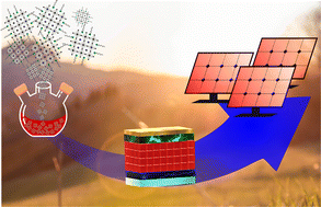
Perovskites are in the hotspot of material science and technology. Outstanding properties have been discovered, fundamental mechanisms of defect formation and degradation elucidated, and applications in a wide variety of optoelectronic devices demonstrated. Advances through adjusting the bulk-perovskite composition, as well as the integration of layered and nanostructured perovskites in the devices, allowed improvement in performance and stability. Recently, efforts have been devoted to investigating the effects of quantum confinement in perovskite nanocrystals (PNCs) aiming to fabricate optoelectronic devices based solely on these nanoparticles. In general, the applications are focused on light-emitting diodes, especially because of the high color purity and high fluorescence quantum yield obtained in PNCs. Likewise, they present important characteristics featured for photovoltaic applications, highlighting the possibility of stabilizing photoactive phases that are unstable in their bulk analog, the fine control of the bandgap through size change, low defect density, and compatibility with large-scale deposition techniques. Despite the progress made in the last years towards the improvement in the performance and stability of PNCs-based solar cells, their efficiency is still much lower than that obtained with bulk perovskite, and discussions about upscaling of this technology are scarce. In light of this, we address in this review recent routes towards efficiency improvement and the up-scaling of PNC solar cells, emphasizing synthesis management and strategies for solar cell fabrication.


image file: d2nr05043a-p1.tif

Lucas Scalon

Lucas Scalon graduated in Chemistry from the Federal Technical University of Parana in 2018. Since 2019, he is a Ph.D. student in Chemistry at the University of Campinas, with an exchange internship at the Integrated Center for Applied Physics and Photonic Materials (IAPP) at the Technische Universität Dresden. His current research is focused on chiral perovskites and interface engineering of perovskite solar cells.

image file: d2nr05043a-p2.tif

Flavio Santos Freitas

Flavio Santos Freitas received his Bachelor degree in Chemistry from the Federal University of Uberlandia (2007), Master (2009) and PhD (2013) degrees in Chemistry from the University of Campinas. Since 2019, he is a Professor at CEFET-MG, Brazil. His current research is focused on metal chalcogenides for solar energy conversion.

image file: d2nr05043a-p3.tif

Francisco das Chagas Marques

Francisco das Chagas Marques is Full professor at the Gleb Wataghin Physics Institute, University of Campinas (UNICAMP), from where he received his Ph.D. degree in physics in 1989. He was a postdoctoral fellow at Harvard University, visiting professor at the University of Utah, and visiting researcher at SCIRO, Melbourne. He has published over one hundred research papers working in the development and study of optoelectronic, structural, and thermomechanical properties of amorphous, microcrystalline, and nanostructured materials and in the manufacture of photovoltaic devices.

image file: d2nr05043a-p4.tif

Ana Flávia Nogueira

Bachelor's degree in Chemistry from the University of São Paulo (1996), Master (1998), and PhD degrees in Chemistry from the University of Campinas (2001). She worked as a postdoctorate fellow at the Imperial College, UK, in 2001–2002 and as visiting researcher at Stanford University from 2017–2018. At the moment, Ana Flavia is Full Professor at the Institute of Chemistry at UNICAMP and Director of the Center for Innovation on New Energies (CINE). Prof. Nogueira's research focuses on the development of functional (nano)materials and their application in solar energy conversion. She has experience in the field of perovskite solar cells, perovskite quantum materials, and dense energy carriers.


1. Introduction

Since the first communication on the perovskites applied in solar cells1 the scientific community has initiated a true revolution in several fields. From the search for new perovskite-based materials2–7 to attempts to understand the formation, self-assembly, and crystallization,8–10 the mechanisms of charge generation and charge transfer10,11 perovskites already have their place in the development of optoelectronics. When we take a look at the advance in solar cells, many scientific works have presented numerous ways and possibilities to bring the benefits of perovskites into products for the industrial community through studies with different architectures,1,12–14 small to large area devices,13,15–22 and stability tests.17,23,24 Predictably, perovskite nanocrystals (PNCs) have not been slow to enter this race. Their high quantum confinement regime, achieved by decreasing the dimensionality of perovskite from 3D (bulk) to 0D (quantum dots), has been shown to be excellent for application in light-emitting diodes (LED) and, more recently, in photovoltaic devices. When comparing PNC-based vs. bulk-perovskite-based solar cells, the first displays significant benefits for the photovoltaic technology establishment, as it demonstrates improved stability of the photo-active phase, greater bandgap control, and high photovoltages for solar cells. In addition, modern deposition technologies are compatible with PNCs, since solution-based methods are the most suitable for industrialization using roll-to-roll technology.15,18,21,25

Despite the benefits, the integration of PNCs in solar cells is recent. The first report dates from 2016,26 and the efficiency of these devices still lack far behind the conventional perovskite bulk-based solar cells. As a matter of comparison, the record efficiency for bulk-based devices is 25.7%,27 whereas for PNC-based ones is ∼16%.28 The progress in this area toward improved efficiency and further upscaling requires advances in terms of synthesis protocols, comprehension of surface chemistry, the understanding of the fundamental mechanisms of nanocrystal growth and degradation, as well as device manufacture. When we consider upscaling strategies, several studies and reviews have addressed bulk perovskite-based devices13,15–17,19,20,22,29,30 and PNCs in LED applications31–34 or perspectives regarding their use in solar cells,18,25 leaving a gap in scientific reports about these materials applied in large-area solar cells. Here, we contribute to this discussion by emphasizing the application of PNCs in solar cells and approaches to integrating them into large-area modules. To reach this goal, we start to discuss the main properties of PNCs, the state-of-art of synthetic routes, and strategies to fabricate efficient and stable photovoltaic devices. This background information provides a basis to draw a path toward the upscaling of PNC-based solar cells.

2. Metal halide perovskite nanocrystals

2.1 Fundamental properties of the nanocrystals

Metal halide perovskites (MHP) have the general chemical formula ABX3, in which A is a monovalent organic or inorganic cation (e.g. methylammonium (MA+), formamidinium (FA+), cesium (Cs+)), B is a divalent metal (Pb2+ or Sn2+) and X is a halide anion (Cl, Br, and/or I). Three-dimensionally and ideally, it organizes as a cubic structure comprised of a share-corning lead (or tin) octahedron ([Pb(Sn)I6]4−) with the A-site cation in the cubo-octahedral void formed by eight octahedrons (see Fig. 1a). By varying the A, B, and X species, it is possible to obtain a plethora of different perovskite compositions, allowing fine control of the MHP structural, optoelectronic and photophysical properties.2,35–40
image file: d2nr05043a-f1.tif
Fig. 1 (a) Crystal structure of an ABX3 perovskite. (b) Dependence of the bandgap on the size of the material. The quantum confinement increases the bandgap going from bulk 3D to the quantum dot 0D. (c) Schematic illustration of the de Broglie wavelength confinement with the decrease in the material's size. (d) Schematic illustration of the micelles formed by the capping ligands: the polar head of the molecule interacts with the perovskite QD while the apolar tail interacts with the solvent. (e) Chemical structures commonly used capping ligands.

Another method to control the MHP's properties is changing its dimensionality rather than composition. Going from bulk 3D to 0D quantum dots (QD) the energy band structure changes from continuous to discrete (i.e., quantized) (Fig. 1b),41–43 in which the electron can only occupy specific energies in the system. The effect of the quantization can be visualized in the electronic absorption spectra of the QDs as sharp and well-defined peaks,44,45 a feature that becomes less prominent as the size increases and the material assumes a bulk-like behavior. Another particularity is the dependence of the bandgap (Eg) on the NC size. This happens because as the material's size becomes smaller than the Bohr radius (the average separation length between electron–hole pairs generated by photoexcitation), the de Broglie wavelength of a free electron (or hole) becomes highly confined inside the particle (Fig. 1c),46 making the Eg of the QD dependent on the size: decreasing the size, increases the Eg.47 The explanation for this phenomenon lies in the solution of the Schrödinger equation for a particle confined in a three-dimensional system (case of a 0D QD), which tell us that the energy of the levels is inversely proportional to the square of the wall thickness, i.e., the nanoparticle size. In other words, narrow walls have more wide-spaced levels, resulting in higher Eg.48,49 In this sense, the variation of the NC size can be used to control the confinement regime, which ultimately affects the material's bandgap. Let us take the CsPbBr3 NC as an example. Its exciton Bohr radius is about 7 nm.50 As size decreases to <7 nm, the electron energy levels assume a discrete rather than continuous energy landscape (see Fig. 1b), causing the material to fall into the quantum confinement regime.51 Based on the size, we can classify these materials in two different regimes: a high confinement regime when the NC dimensions are ≪7 nm, and a low confinement regime when the NC dimensions are ≫7 nm,48,52 which will affect the optoelectronic properties of the material.

Because of its small size, the surface/volume ratio of NC is large. Considering a spheric NC, its surface area can be expressed as 4πr2, and its volume 4/3πr3; here r is the radius of the sphere. Therefore, the surface/volume ratio is 3/r. In this sense, a 7 nm diameter particle will have a surface area equal to 154 nm2, and the surface/volume ratio is ∼8 × 10⁸ m2/m3. For this reason, there are much more atoms on the surface than in the interior of the NC, which is opposite to bulk materials, in which the surface is only a tiny fraction of the whole.53 As a consequence, the chemical potential (i.e., reactivity) of the surface is very high. To decrease the surface's reactivity, the NC tends to agglomerate with time to form large domains, which causes loss of the quantum confinement regime (note that, in this situation, the material's size will increase). To avoid this natural tendency of agglomeration, capping ligands are required to stabilize the material by forming micelles, as schematized in Fig. 1d. Commonly, alkylamines, carboxylic acids, and phosphonic-based ligands are used (Fig. 1e).54–58 These molecules are composed of a polar head that binds to the NC surface, and a long hydrocarbon tail that interacts with the solvents.

2.2 Size-dependent properties beyond bandgap

Besides bandgap, several other properties can be affected by size variations. For instance, the Stokes shift (energy difference between the emission maxima and the excitonic peak in the absorption spectra) was observed to be large for low-size NC; this seems to be independent of the composition, at least regarding the halide for CsPbX3 NC-series, as shown in Fig. 2a.59–62 First-principle calculation revealed the presence of a confined hole state (CHS), with a size-dependent energetic separation in respect to the valence band (VB) edge states,63 which explains the dependence of Stokes shift with the NC size. It was verified that the absorption from CHS to the conduction band (CB) is dark (not seen in the UV-Vis absorption spectra) due to the low density of state (DOS). As a result, the absorption spectrum is dominated by only VB → CB edge state transitions. Nevertheless, non-radiative relaxation can occur from CB edge states to CHS, which causes CHS to be analyzed through emission spectra rather than absorption. The net result is that the photoexcited electrons lose the absorbed energy and populate a state with higher energy (i.e. CHS) compared to the state from where they were excited (that is, VB edge states). In this way, the emission spectra will be red-shifted, which in turn increases the Stokes shift. The possibility to obtain materials with a large Stokes shift is particularly interesting for solar cell applications, due to avoiding reabsorption losses,64 and also has application in luminescent solar concentrators,65 which is attractive to improve solar cell performance.
image file: d2nr05043a-f2.tif
Fig. 2 (a) Dependence of the Stokes shift with the variation of NC size from three compositions of PNC: CsPbCl3, CsPbBr3, and CsPbI3.62 (b) Simulated XRD of α-, β-, and γ-phase of CsPbI3 PNC; (c) experimental XRD of CsPbI3 with different NC phases.66 (d) Calculated (empty symbols) and experimental (filled symbols) charge separation (CS) and charge recombination (CR) rates of CsPbI3 QD-rhodamine and their variation with the NC size.68 (a) Reproduced with permission from ref. 62. Copyright 2020 American Chemical Society. (b and c) Reproduced with permission from ref. 66. Copyright 2019 American Chemical Society. (d) Reproduced with permission from ref. 68. Copyright 2019 AIP Publishing.

Additionally, the size was revealed to impact the lattice strain and crystal phase of the PNC.66 For instance, as the CsPbI3 size increases from 5.7 to 15.3 nm, it loses the α-phase cubic symmetry, approaching γ-phase symmetry with an orthorhombic structure for larger NC, as can be seen from the XRD patterns in Fig. 2b and c. The results also showed that small NC experiences higher tensile strain and revealed octahedra tilt as the size increases. Small NC also seems to be less prone to cubic-to-tetragonal phase transitions at low temperatures (120 K), whereas the large ones suffer from phase transition because of changes in electrical polarization.67

Furthermore, Shang et al. revealed a size dependence on the charge separation (CS) and charge recombination (CR) rates from CsPbI3 QD to rhodamine (electron acceptor) by varying the NC size from 11.8 to 6.5 nm, as depicted in Fig. 2d.68 In this regime of weak to moderate quantum confinement regime, the authors found that the size dependence of the rates is mainly controlled by the orbital overlap between the QD and the rhodamine.69 As a result, the electron transfer is not dependent on the energy level matching between the donor (in this case the QD) and the acceptor (rhodamine) lowest-unoccupied molecular orbital (LUMO), as observed for QD with a strong quantum confinement regime (i.e., small NC size).69 These findings are particularly interesting for optoelectronic applications, in which charge separation and charge recombination dictate the main working mechanism of the devices. It should be highlighted that this study investigated the dynamics of charge transfer in the solution state. Translating those findings to the thin-film state should be analyzed carefully, since the solvent may play a role in the charge transfer mechanism.

2.3 Tuning PNC composition and the impact on the material's properties

In a lead halide perovskite material, the valence and conduction bands are mainly formed by Pb 6s and X np (where n is an integer) and Pb 6p and X np orbitals, respectively. Therefore, tuning the composition of the PNC results in a change in the position of both CB and VB.70,71 In addition to the direct impact of the composition on the bandgap, other properties of the material can be influenced. For example, for mixed halide composition in CsPbBrxI3−x NCs, an increase in the iodide content causes additional centers for hole trapping.72 This occurs because of the presence of Br and I-rich regions,73,74 which causes the holes created in the Br-rich NC, which has a higher bandgap, to move to the I-rich NC, which has a lower bandgap.72 Similarly, alloying Cl/Br and Br/I leads to a bathochromic shift of the emission spectra as the bromide or iodide content increases due to the formation of large particles and because of the influence of the anion in the electronic structure of the perovskite.2,75 This is an excellent alternative to tuning the color emitted by the material. Furthermore, we demonstrated recently that the presence of an absorption tail in low-temperature absorption spectra of CsPbX3 (X: Cl, Br, I) is indicative that iodide-based NC is less defect tolerant than the bromide and chloride,76 which suggests that iodide may be generating more shallow levels near the band edges when compared to the other two halides. Another interesting impact of the halide anion is in the coherent vibration of the wave packets generated upon photoexcitation, which was found to be dependent on the halide anion for the case of FAPbX3 NC (X: Br and I).77 This happens because the FA rotation in the Br-base NC is higher compared to the I-based, which means that there is a stronger interaction between FA and [PbBr6]4−.77

In addition to the halide anion, the A-site cation may also influence the nature and properties of the PNCs. In the APbBr3 series, in which A: Cs, MA, and FA, the NC size is larger for the ones based on the organic cations.78Fig. 3a shows TEM images of CsPbBr3, MAPbBr3, and FAPbBr3. The NC size goes from 9.2 nm for the inorganic-NC, to 17.3 and 12.9 nm for MA-, and FA-based NC, respectively, which directly impacts the absorption and emission features.78 The energy separation between dark and bright states decreases from Cl to Br and I, and with the replacement of Cs by FA (Fig. 3b).79 This is important because the thermalization of the excitons towards dark states reduces the light emission efficiency, mainly because of the spin and momentum-forbidden transition to the ground state.80 In this sense, having a large energy separation between the bright and the dark excitonic states should, in principle, improve the radiative recombination of the NC. However, the impact of the dark exciton on the performance of optoelectronic devices based on MHP NC is still understudied.


image file: d2nr05043a-f3.tif
Fig. 3 (a) TEM images, and absorption and emission features of a series of APbBr3 PNC (A = Cs, MA or FA).78 (b) Schematic illustration of energy separation between the dark (spin-forbidden transition to ground state) and bright (allowed the transition to ground state) and its dependence on the X-site cation specie.79 (a) Reproduced with permission from ref. 78. Copyright 2018 American Chemical Society. (b) Reproduced with permission from ref. 79. Copyright 2018 American Chemical Society.

2.4 Surface-dependent properties

It is well-known that PNCs are tolerant to typical defects found in perovskite materials as vacancies, surface states, and grain boundaries.81 In a 10 nm PNC, for instance, it is estimated one defect per ∼102–107 cm−3,82 whereas bulk perovskites have defect densities in the range of 1011–1016 cm−3.83,84 For a nanoscale regime, these point defects are mostly at the surface of the NC because of the huge number of atoms exposed and the ionic nature that allow halide atoms to escape from the surface.81 Also, stability may drive bulk-type defects in the core towards the surface,82 which is explained by the structural instability and the high ionicity of PNCs.81 This characteristic is also responsible for the occurrence of ion exchange reactions for halide anions85 and bivalent cations.86 The intrinsic defect tolerance of PNC is predominantly ascribed to its electronic band structure. For example, in CsPbX3 NCs, the valence band maximum (VBM) consists of the antibonding interaction between the X np orbitals (n = 5, 4 and 3 for X = I, Br, Cl, respectively) and the Pb 6s orbitals, while the conduction band minimum (CBM) results of antibonding interaction between X np and Pb 6p orbitals.87 This means that the VBM has antibonding features, and the CBM, has a strong spin–orbit coupling. As a consequence, the defect states of PNCs are within (or near) the VBM or CBM rather than in the bandgap, leaving it free of trap states.81 The proximity to the band edges makes the thermal energy, kBT, enough to the defect states become filled with charge carriers at room temperature.

Regarding the defect tolerance, ten Brinck et al.82 found that the interstitials defects in CsPbBr3 nanocrystals are energetically favored and the PNC tends to accommodate ionic pairs (i.e. CsBr or PbBr2) in the lattice. The authors noticed that midgap states can arise only from halide species independently of the interstitial defect, either cationic or anionic. These localized states triggered by the halide ion only cause trap states if the anion occupies surface positions that point outward the surface. The excess of halide species against the available halide surface sites exemplifies this situation, where its nonbonding lone electron pairs produce trap states. Since surface passivation can form halide-hydrogen bonds on the surface, this treatment, beyond avoiding agglomeration, could inhibit the capture of the excited electrons by the surface traps.87,88 Vacancy defects by removing ions from either the surface or the core have negligible densities since the energy required to create vacancies is in the range of 1.4 to 2.3 eV. It means that ionic extraction must be induced from species around PNC, which is more effective at the surface, and denotes how surface chemistry plays an important role in the NCs’ stability.82

As will be addressed in the next sections, surface ligands are molecules that bind to the surface and drive the synthesis through tunable sizes, dimensionalities, morphologies, and the related aspects of PNC including stability and optoelectronic properties. Stability is improved when surface passivation is carefully selected, although an effective surface shelling may inhibit the charge transport and deteriorate the device's performance.78,88–90 Furthermore, surface ligands are labile and the detachment of these species can be promoted by organic solvents used in the synthesis or purification due to moderate solubility, and also through neutralization, e.g., oleylammonium bromide being converted into oleylamine and HBr. The detachment mechanisms lead to the elimination of ion pairs from the PNC surface, leaving vacancies and exposing undercoordinated halide ions, which are responsible to trap states and the reduced optical response.90

An elegant way to reduce surface defects associated with an appropriated surface coverage is to interconnect the PNCs to form crosslinks. This strategy not only enhances the PNC stability but also influences optical and solubility properties.81 Li et al.,91 for example, used butylphosphonic acid and 4-ammonium chloride in MAPbI3 NCs, and demonstrated that hydrogen bonds through N–H⋯I and P-OH⋯I are intermolecular interactions sufficient to link PNCs. The solution was then spin-coated onto TiO2 and annealed at 100 °C giving rise to a homogeneous layer and solar cells with an efficiency of 16.55%.91 The use of ligands able to form stronger bonds, i.e. covalent bonds, between PNCs is another interesting approach to reaching/improving PNC-PNC connections. Liu et al.,92 used nitrene radicals from the photochemistry of bisazide under UV irradiation to form covalent C–N bonds with long alkyl chains from ligands on neighboring PNCs, creating PNC networks and retaining their morphological properties. This method for direct optical patterning of perovskite NCs with ligand cross-linkers (DOPPLCER) does not require ligand exchange and is universal to PNCs with various compositions, sizes, surface chemistry and synthesized by different methods. The multicolored patterning of various PNCs via DOPPLCER, retained their size-defined, and emission features before and after patterning (CsPbBr3 and CsPbCl3−xBrx, except for the unstable red-emitting CsPbI3−xBrx).92 Post-patterning anion exchange with iodide salts converts CsPbBr3 NCs to CsPbI3−xBrx patterns and suggests that the PNC cores remain reactive and accessible probably due to the low degree of cross-linking, in contrast to cross-linked ligands via X-ray irradiation or with polymeric ligands.93–95 Furthermore, the method shows the preservation of optical absorption and emission characteristics before and after cross-linking at mild conditions92 without a high-energy source or a ligand exchange process. UV irradiation has promoted crosslinking reactions between PNCs using a polymer backbone containing a cinnamoyl group95 or 2,2-dimethoxy-2-phenylacetophenone (DMPA).96

2.5 Mechanism of charge generation and dissociation in PNCs

A great attribute of PNCs is their tunable composition of cations and anions delivering a wide spectral emission range (400–700 nm with CsPbX3 and MAPbX3, and up to 800 nm with FAPbI3 NCs), typically with a full width at half-maximum (FWHM) of 12–50 nm.97 The A-site cation (e.g. FA, MA and Cs) does have a subtle effect on the bandgap due to the distortion of the cubic crystal structure, but it does not contribute expressively to the conduction and valence bands in terms of density of states.98

From computational calculation based on MAPbI3 NCs, the VBM and CBM are characterized by the same k-vector, giving to PNCs a direct bandgap nature with an abrupt absorption onset at the bandgap energy, Eg. Moreover, the bands around the VBM and CBM exhibit a similar curvature. Upon photoexcitation, electron–hole pairs are generated and remain coulombically bounded forming an exciton that required activation energy on the order of the thermal energy, kBT, to be dissociated into mobile charges.99 The single exciton formation involves an electron in the conduction band coulombically bound to a hole in the valence band with four temporal regimes. In the first three, the electron stays within the CB in intraband processes (coherent, non-thermal, and hot excitation regime), followed by one last isothermal regime which involves an interband transition from CB to VB, the exciton recombination.

Prior to electron–hole recombination, a strong spin–orbit interaction, or L–S coupling, between the spin and the orbital motion of the carriers caused by the presence of heavy atoms like Pb in their crystal structure results in the triplet and singlet exciton states, with the last having the lowest energy. However, when L–S coupling is combined with the crystal or inversion symmetry breaking (i.e., Rashba effect), it reduces the triplet state energy to below the singlet state, leading to bright triplet states with high photoluminescence quantum yield (PLQY) and fast radiative lifetimes. These low excitonic states are nearly mixed and not distinguishable at room temperature, but experimentally observed at cryogenic temperatures.11,100,101 Therefore, the energetic order of bright and dark states is still under debate, since bright-to-dark relaxation can be induced by magnetic field, leading to the interpretation that the bright-to-dark spin relaxation is inhibited due to the faster radiative decay from the bright state than their relaxation to the dark state.102

PNC composition influences exciton binding energy since the atomic orbital of the species contributes to both valence and conduction bands. As the halide species changes from Cl, to Br and to I in PNCs, due to contribution to the VBM, the exciton binding energy decreases, while the exciton recombination, carrier trapping, and hot carrier cooling times become longer. When the A-site cation is changed from FA to MA, and Cs, an increase in the carrier cooling time due to the decrease in the strength of the carrier-phonon interaction is observed. Quantum confinement also affects exciton dynamics, on account of their small Bohr exciton diameters,102 estimated to be 5, 7, and 12 nm for CsPbX3 NCs, respectively to Cl, Br and I.2 Thus, the photo-excited electrons and holes in PNC are physical manifestations of “particles in a box”, which promotes fast and efficient radiative recombination due to spatial confinement within the NC.103

The time-resolved spectroscopy studies provide a comprehensive understanding of photoinduced processes, such as the excited-state lifetimes and charge carrier transfer kinetics. Especially, transient absorption spectroscopy (TAS) shows that the radiative lifetimes of CsPbX3 go from 1 to 29 ns with accelerated decays from I-based toward Cl-based PNCs. For ligand-capped PNCs, a long-lived exciton lifetime is attributed to a lower density of trap states.81

In addition to single excitons, the generation of multiexcitons is expected to boost the photocurrent and performance of photovoltaic devices, overcoming the Shockley–Queisser efficiency limit. Bi/multiexcitons can be produced by an energy excess released by a photon with energy at least twice the bandgap, creating additional electron–hole pairs instead of being dissipated through thermalization. However, these bi/multiexctions recombine non-radiatively through the Auger process, in which the recombination energy of one exciton is transferred to another charge carrier of the same PNC, therefore their extraction using an electron/hole acceptor prior to the Auger recombination is mandatory.104 If a multiple exciton generation is observed for the PNC, all of the four temporal regimes previously discussed may overlap. Thus, the mechanism of multiple exciton generation is not an instantaneous process, that is, the energy excess of the hot carrier is not transferred directly to the lowest state. It starts with the excitation energies just above the energy limit of 2Eg. Then, the additional carriers appear after those initially generated upon photon absorption in a state with longer cooling time, probed by studies with FAPbI3 NCs with sizes of 7.5 and 9.8 nm, and CsPbI3 with 11.5 nm, using an excitation energy of ∼2.25Eg and ∼2.4Eg, respectively.102

When the presence of mixed halides is evaluated in PNCs with Cl doping (CsPbI3−yCly and FAxCs1−xPbI3−yCly) the average photoluminescence (PL) lifetime was found to be ∼3 times longer compared to CsPbI3. The authors attributed the increased PL lifetime to the return of the photogenerated charge carriers to the band-edge state by thermal excitation after the decay to the trap states. In this work, suppression of the Auger recombination rate and consequent lengthening of biexciton lifetime was demonstrated using C60 as an electron acceptor, with single exciton dissociation followed by electron transfer from CsPbI3−yCly to C60 revealed by a biexponential dynamics with a fast component of 18–45 ps. The multiple exciton transfer was observed for CsPbI3−yCly and FAxCs1−xPbI3−yCly NCs, and it was found that the biexciton lifetime is long enough (∼195–205 ps) to be extracted by fullerene as well.104 Studies with PNC in contact with redox-active molecules, e.g. the CsPbBr3-rhodamine B, showed that the Föster mechanism (related to energy transfer over larger distances (up to 12 nm)) is dominant, in agreement with the expected and measured rate constant of energy transfer (kET). For Cl-rich nanocrystals, the measured kET is higher, indicating that the Dexter mechanism over shorter distances (1–2 nm) in these systems becomes dominant. These results demonstrate that PNCs present a unique susceptibility to chemical transformations able to access a range of energy and electron transfer process.100 Different hetero and homojunction architectures could be employed to facilitate efficient charge extraction, e.g. PEDOT:PSS and/or metal oxides.105 Terahertz kinetics of MAPbI3 show that, in presence of a metal oxide with a high electron affinity like TiO2, the charge mobility is ∼7.5 cm2 V−1 s−1, lower than in neat MAPbI3 (∼20 cm2 V−1 s−1), supporting the electron injection from MAPbI3 to TiO2.106

3. Synthesis of perovskite nanocrystals

Bulk-perovskite thin films can be prepared through a precursor solution containing the lead and A-site cation salts in the desired solvent, and deposited by a large variety of techniques such as spin-coating,98,107 spray,108 inkjet printing,109,110 blade-coating,111,112 thermal evaporation,113,114 rf-sputtering,114–118 slot-die coating,119 chemical vapor deposition,120 and atomic layer deposition.121 2D layered perovskite solar cells have been mainly deposited by solution processes, and also involve the preparation of a precursor solution.122,123 In contrast, the deposition of PNC thin films requires the previous synthesis of the nanocrystals prior to deposition using one-step wet processes. On account of that feature, we will introduce three methods used to fabricate PNC: (i) hot injection, (ii) ligand-assisted reprecipitation, and (iii) ultrasonication, underlying the strengths and weaknesses of each one.

3.1 Hot injection method

The hot injection method (Fig. 4a) is one of the most used because of the high quality of the materials obtained, with a good size and shape distribution, besides established synthesis protocol for various MHP compositions. It consists in injecting the A-site cation precursor, such as CsOAc, MAI, or FAI, into a hot solution containing the Pb source, e.g. PbCl2, PbBr2, or PbI2, dissolved in a high-boiling point solvent, such as octadecene, in the presence of capping ligands, e.g. oleylamine (OLA) and oleic acid (OA) (see Fig. 1e).2 Besides conferring colloidal stability, these ligands help to dissolve the PbX2 precursor and passivate some defects present on the NC surface. The solution containing the lead-precursors and ligands is heated to dissolve the materials, and when it reaches the desired temperature, the A-site cation precursor solubilized in a high-boiling point solvent is added, resulting in the formation of APbX3 NCs in a matter of seconds. Usually, high temperatures (>150 °C) are required to solubilize PbX2, but the choice of the proper synthesis temperature will depend on the solubility of the precursors, the rate of growth, the nucleation of the NC, and also the thermal stability of the materials formed.124 Synthesis temperature will also influence the final properties of the NC, as we will illustrate in the following sections.
image file: d2nr05043a-f4.tif
Fig. 4 (a) Schematic illustration of the hot-injection method used to produce perovskite quantum dots (QD). HPB is for high-boiling point solvents. (b) Dependence of the PLQY with the dielectric constant of different solvents used to wash the NC in the purification step.125 (c) Variation on the emission peak and photoluminescence quantum efficiency (PLQE) with the concentration of octyl phosphonic acid (OPA) at a fixed reaction time (300 s).126 (d) Variation of nanocrystal size and PLQE with the reaction time at a fixed concentration of OPA (0.3 M).125,126 (a and b) Adapted with permission from ref. 125 Copyright 2018 American Chemical Society. (c and d) Adapted with permission from ref.126 Copyright 2021 American Chemical Society.

Purification is the next step after synthesis. It is required to remove unreacted precursors and the excess ligands present on the surface, which otherwise can act as trap centers for photogenerated charge carriers.127 Usually, the purification is performed by redispersing the NC in polar solvents (e.g. methanol, acetone, or ethyl acetate), known as “poor solvents”, which do not have the ability to solubilize the NC. This dispersion is then centrifuged to recover the powder – the centrifugation speed can be adjusted to collect the NCs based on their size. These solvents will solubilize the unreacted precursors whereas the NC will precipitate after centrifugation. The number of washing steps should be optimized since it can lead to ligand desorption, compromising the colloidal stability, and elemental composition changes, modifying the optoelectronic properties of the NC.128 The choice of solvent is also important since it influences the optical properties of the PNC. Fig. 4b correlates the PLQY of CsPbBr3 NC dispersed in toluene after washing it with solvents of varied dielectric constant (ε).125 As can be seen, the region with the highest PLQY values is between 5 < ε < 10, and, among the solvents used, the best one was diglyme (ε = 7.23).125 The authors found that poor solvents with low dielectric constant can allow multiple steps of NC washing without compromising the properties of the material. An interesting alternative to the centrifuge purification method was proposed by Tong et al.129 They used lauryl methacrylate (LMA) as a solvent during the synthesis of CsPbBr3 NC. It possesses a high boiling point, and a hydrophobic chain to stabilize the colloidal material. Adding polyurethane acrylate oligomer, and applying UV-light it can be polymerized, yielding a green-emissive composite material comprised of the CsPbBr3 NC embedded into the polymeric network with PLQE as high as 85%, which keeps stable for 100 h.

One of the main challenges of the hot-injection method is the high temperature required for the synthesis, which makes the scalability difficult and very energetically expensive. Nevertheless, room-temperature alternatives to the hot injection method have been studied.126,130,131 For example, a room temperature strategy for synthesizing CsPbBr3 NC was proposed by using octyl phosphonic acid (OPA) and didodecyldimethylammonium bromide.126 The first can control the nucleation of the NC, while the last is employed to quench the growth. By controlling the concentration of OPA and the reaction time, it was possible to tune the size of the NC, as shown in Fig. 4c and d.126 Another alternative is reducing the solvent's boiling point through pressure reduction, which decreases the synthesis temperature by ∼40 °C.132 All of these alternatives facilitate the process's scalability and the industrial manufacture of PNC in solar cells and other optoelectronic devices.

3.2 Ligand-assisted reprecipitation method (LARP)

One of the major advantages of this method compared to the hot injection is the possibility to fabricate PNC at room temperature. It consists in dropping a solution containing the perovskite precursors (A-, B-, and X-site precursors) solubilized in a good solvent (i.e., a solvent that dissolves the precursors), e.g. dimethylformamide (DMF) or dimethylsulfoxide (DMSO), into a solution of the capping-ligands in a poor solvent (i.e., a solvent that does not dissolve the precursors), e.g., hexane, diethyl ether, chloroform, or toluene, as schematically illustrated in Fig. 5a.133 Conversely, it is also possible to inject the solution of the amines in the poor solvent into the precursor solution. Note that the main difference here compared to the hot injection method is the existence of a precursor solution for the PNC, similar to the preparation of thin films of 3D perovskites.
image file: d2nr05043a-f5.tif
Fig. 5 (a) Scheme of the ligand-assisted reprecipitation (LARP) method: a solution containing the PNC precursors dissolved in polar solvents is dropped into a solution of the capping ligands, leading to the precipitation of the NC, which is recovered and purified by centrifugation.133 (b) Schematic illustration of the NC size variation through the tuning of FA/Pb ratio, and the different morphologies obtained for low and high FA/Pb ratio.139 (c) Enhancement of the solubility of MAPbI3 perovskite in acetonitrile (ACN) by bubbling into methylamine (MA) gas, resulting in a clear yellow solution.140 (d)–(f) CsPbBr3 nanocubes obtained from a synthesis using PbBr2 dissolved in toluene. The complete dissolution of this salt in the apolar solvent was assisted by tetraoctylammonium bromide (TOAB), yielding high fluorescent PNC.141 (g) Illustration of the method used for the in situ synthesis of FAPbBr3 NC directly into the desired substrate.142 (a) Reprinted with permission from ref. 133 Copyright 2015 American Chemical Society. (c) Reprinted with permission from ref. 140 Copyright 2019 American Chemical Society. (d–f) Reprinted with permission from ref. 141. Copyright 2017 American Chemical Society. (g) Reprinted with permission from ref. 142. Copyright 2018 American Chemical Society.

The heart of this technique lies in the different solubility of the perovskite precursors in the solvent mixture. Strictly speaking, the precursors are highly stable (soluble) in the polar solvents, but when in contact with a poor apolar solvent it precipitates immediately, forming the NC stabilized by the capping ligands that coordinate Pb-sites on the surface.134 To achieve small NCs with expressive quantum confinement effect, the chain length of the capping ligands should be optimized.133,135 Capping ligands with a very small chain, for instance, will cause NC aggregation, thereby compromising the quantum confinement-dependent properties. On the other side, long-chain molecules will preclude the NC-to-NC electronic coupling and difficult charge extraction in the system. In addition to capping ligands, several other parameters will impact the final properties of the NCs, including the synthesis temperature, ligand/precursor concentration, and choice of solvents.134–137

Typically, the purification is performed by multiple centrifugation steps of the solids suspended in the poor solvent, which is analogous to the described in the hot injection method. This allows the removal, at least partially, of the unreacted capping ligands, A- and B-site precursors. The choice of the solvent in this step is also crucial since it can change the emission profile and, as a consequence, the properties of the PNC.138 The purification with toluene and chlorobenzene, for instance, results in a broad and multiple peak emission due to a large size distribution. In contrast, hexane, a low polarity solvent (polarity equals 0.06), yields a single and narrow emission peak as a result of the narrow size distribution.

One of the major issues of this technique is the use of highly coordinated polar solvents to solubilize the perovskite precursors.130,134,140,143 The strong coordination ability between those solvents and PbX2 precursors results in the crystallization of the perovskite phases from PbX2-solvent complex intermediates, causing the solvent molecules to remain in the final product.144 These defective perovskites are more prone to degrade in the presence of water or oxygen. Strategies to circumvent this issue have been reported. For example, PbX2 (X = Br, I) was dissolved in toluene with the addition of small amounts of oleic acid (OA) and oleylamine (OLA).139 Concomitantly, the A-site source (FA-acetate) was dissolved in OA using ultrasonication. By mixing both solutions, the crystallization of the NC occurs spontaneously at room temperature, and the size can be controlled by adjusting the ratio between the A-site cation and the Pb2+ precursors (Fig. 5b). Acetonitrile saturated with methylamine has also been used to solubilize the MAPbI3 precursors (Fig. 5c).140 This solution was then added into a mixture of toluene, OA, and OLA, yielding cubic NC of MAPbI3 with 10–15 nm size, and PLQY >90%. This was possible because methylamine can form a liquid perovskite phase with the MAPbI3 perovskite with the chemical formula CH3NH3PbI3·xCH3NH2, improving the solubility of the perovskite in the acetonitrile (ACN), which is a less coordinated solvent when compared to DMF and DMSO, for instance.145 Besides, PbBr2 was found to be completely soluble in toluene in the presence of tetraoctylammonium bromide (TOAB).141 The subsequent swift injection of this solution into a Cs2CO3 solution in oleic acid and toluene resulted in the formation of highly emissive CsPbBr3 nanocubes with ∼13 nm (Fig. 5d–f).

Using the LARP method it is also possible to fabricate in situ PNC films. The process is quite similar to the ex situ mentioned in the lasts paragraphs, the difference is that the perovskite precursor solution containing the capping ligand is coated into a substrate, and then the poor solvent is dropped, causing the supersaturation of the film due to the removal of the polar good solvent and the consequent precipitation of the NC (Fig. 5g).142,146

3.3 Ultrasonication method

The use of ultrasound to synthesize colloidal PNC was introduced by Tong et al.147 for the synthesis of CsPbX3 perovskite NC from tip sonication of CsCO3 and PbX2 in the presence of organic ligands, OA and OLA, using mineral oil or octadecene as solvents. A scheme of the synthesis is depicted in Fig. 6a. The formation of a Cs-oleate complex soluble in nonpolar solvents triggers the formation of the PNC. This synthesis approach yielded NCs with cubic and rectangular shapes, sizes in the range of 8–15 nm and varied emission colors depending on the composition (Fig. 6b). From X-ray diffraction (XRD) and transmission electron microscopy (TEM) measurements, it was found that by lowering the Cs content the reaction rate is decreased, favoring a shapeshift from cubic to nanoplatelets (NPLs). The authors investigated the effect of the CsCO3/PbI2 ratio in the PL features of the CsPbI3 NC and found an excellent way to produce NPLs with controlled thicknesses from three to six [PbX]4 octahedra (see Fig. 6c). Almost concomitantly with the previous report, Jang et al.,148 in 2016, used the ultrasonication method to produce APbBr3−xClx PNC by sonicating AX (X = Cl, Br or I), i.e A-site cation precursor, with the lead source (PbX2) and OA (1[thin space (1/6-em)]:[thin space (1/6-em)]1[thin space (1/6-em)]:[thin space (1/6-em)]3 proportion, respectively) in toluene. It was found that the sonication time depends on the solubility of the precursors in the solvent mixture (toluene + OA) and can vary from 30 to 150 min, as indicated in Fig. 6d.148
image file: d2nr05043a-f6.tif
Fig. 6 (a) Schematic illustration of the PNC synthesis, and (b) absorption and emission spectra of the different compositions obtained using the ultrasonication method.147 (c) Variation of the energy gap with the number of layers of CsPbI3 NC prepared from ultrasonication, achieved by controlling the CsCO3/PbI2 ratio.147 (d) Variation of the PL intensity from various times of ultrasonication; the time required to achieve the high PL intensity is dependent on the NC composition.148 (a–c) Reproduced with permission from ref. 147. Copyright 2016 Wiley-VCH. (d) Reproduced with permission from ref. 148. Copyright 2016 Royal Chemical Society.

When compared to the hot injection method, the ultrasonication procedure uses room temperature for the synthesis. This is possible because ultrasonication promotes the formation of bubbles with a high temperature inside.148 Those bubbles help the dissolution of the precursor's salts and cause supersaturation, nucleation, and consequent growth of the PNC. Another advantage is that it is not necessary to use an inert atmosphere during the synthesis to obtain high-quality materials.149 In addition, it can be used to synthesize PNC without the use of polar solvents, such as octadecene and dimethylformamide (DMF). For instance, liquid paraffin was used to obtain CsPbBr3 PNC with shapes varying from 3D nanocubes to 0D QD by adjusting the ratio of the capping ligands and the ultrasound power and time.150,151 Furthermore, the PNCs can be prepared directly from the perovskite powders (e.g., MAPbBr, MAPbI) and PbX2 using OLA and OA as both capping ligands and solvents. The ultrasound breaks the bulk perovskite into NC which, in the presence of the capping ligands, stabilizes the small particles formed.152–154 Although promising, the scaling-up of this process is challenging. The tip of the sonicator has a small size (<1 cm), which could difficult the homogeneity of the reaction, decrease the reaction yield and purity, and affect the NC properties. The scaling up of the ultrasonication method would require, for instance, multiples ultrasound tips into the reaction reservoir to allow a synthesis with appreciable yield.

4. The role of ligand chemistry, and strategies to control perovskite nanocrystals’ size and shape

After introducing the main properties of the PNC and some common methods used to prepare them, we will deepen the discussion on the importance of ligand chemistry, and some opportunities that have been used to control the size and morphology of the PNC through the management of the synthesis conditions.

4.1 Surface ligands

As mentioned in the previous section, the surface ligands decrease the surface chemical potential of the NC and, consequently, improve the stability of the material due to avoiding the aggregation and loss of quantum confinement effect.148 Furthermore, they play a key role in the passivation of defects present on the surface, which are demonstrated to cause midgap states in the energetic landscape of the PNC.82,155,156 Because of this, it is always important to take into consideration the nature of the surface ligand, and their management has been used to control the NC properties as, for instance, the environmental, temperature, light, powder, and suspension stability, as well as the NC size and uniformity.157,158 In addition to the aforementioned effects, the surface ligands can also impact the electronic structure of the NC.155,156 This occurs because the interaction between the ligands and the atoms on the surface of NC changes due to the presence of the capping molecules, which means that the ligand and core experience the electric field of one another.159

The most common ligands used for the synthesis of PNCs are oleic acid and oleylamine. When this acid–base pair is mixed, a chemical equilibrium takes place, with the carboxylic acid protonating the amine to ammonium according to the reaction: R-COOH + R-NH2 ⇌ R-COO + R-NH3+. The –NH3+ group is able to interact with the A-site of the PNCs at the surface, and stabilizes the NC by the formation of three hydrogen bonds with the X ions.160 On the other hand, OA does not bind to the surface of the NC, being present as a free ligand in the solution even after the washing steps of purification.160,161 Since the binding between the ligand and the PNC surface is very dynamic,162 the presence of free OA helps to maintain the colloidal stability of the system. It should be highlighted that despite the role of OLA being well understood by the scientific community, the role of OA is still under constant debate, and it is not clear the mechanisms for the colloidal stability conferred by this molecule.

Several types of surface ligands have been used. We can divide them into monodentate, bidentate, branched, and zwitterions (Fig. 7). The monodentate ligands, which include both OA and OLA, are comprised of one polar head that can interact with the PNC or its precursors, and an aliphatic or aromatic moiety that interacts with the solvent. Bidentate ligands, such as 2,2′-iminodibenzoic acid and 12-aminododecanoic acid, have two polar heads, allowing them to bind at two NCs at the same time. They have been reported to reduce structural disorder at the NC surface,163 and lead to a beneficial passivating effect.164 In these molecules, tailoring the alkyl/aromatic chain is a good alternative to improve the optoelectronic properties of the material, benefiting charge injection and transport.165,166 Another class of ligands are the branched ones, e.g. 2-hexyldecanoic acid, trioctylphosphine oxide (TOPO) and (3-aminopropyl)triethoxysilane (APTES). They are bulky molecules with a large steric hindrance, which is suggested to benefit the formation of small and more uniform NCs.54,158,167 Finally, zwitterionic ligands such as amino acids and phosphocholine have at least two functional groups in their structure: one with a positive charge and another with a negative charge. The use of these molecules as ligands in PNCs has been reported to increase chemical stability and PLQY.168–170


image file: d2nr05043a-f7.tif
Fig. 7 Classes of ligands to be used during the synthesis of PNCs: monodentate, bidentate, branched, and zwitterionic ligands.

As can be seen, there is a plethora of molecules that can be used as surface ligands in PNCs, and it is quite hard to state universal rules for the choice of a proper ligand. In general, what is aimed is a stable and cheap ligand, capable of passivating the surface defects, and conferring colloidal stability to the NCs. In this sense, it is important to know the surface composition of the NC in order to perform modulations in the interaction strength between the ligand and the NC surface, which can be achieved by inserting electron donating or withdrawing groups to tune the electron density over the interacting polar head. This type of modification can also tune the van der Waals interactions among the ligand molecules, which can facilitate the NC-to-NC electronic coupling. The electronic coupling between the nanocrystals is an important aspect to be considered for their application in solar cells. This is because a long hydrocarbon chain can hinder proper electronic coupling and also imposes issues for charge transfer, because of its insulating nature. Therefore, short alkyl/aryl chains are preferred. However, it should be highlighted using these short-chain ligands it is more difficult to obtain small-size NC since they are less effective to prevent aggregation when compared to long alkyl/aryl chains. Therefore, the selection of the proper ligand depends on a plethora of aspects, including the synthetic methodology used, the composition of the NC surface, the density of defects, the morphology aimed, and the desired application for the material.

There is a huge floor for the exploration of new ligands, in particular, the use of functionalized molecules endowed with groups that can properly interact and passivate surface defects on the NC should be considered; we will return to this discussion later on. However, as we will discuss in section 5, attention should be taken to selecting the proper ligand when applying the NC to solar cells is aimed. The reason for this is that the insulating nature of the vast majority of capping ligands decreases the NC-to-NC electronic coupling, hampering the efficient charge separation in the system. At this point, it is clear that the ligand's nature is a crucial part of the integration of PNC into solar cells. Just to mention, short-chain molecules are reported to have a long exciton diffusion length compared to those with long-chain,171 which directly impacts the charge extraction efficiency of the PNC solar cells. However, direct synthesis using short alkyl chain molecules can be challenging, especially because of the decreased solubility conferred by these molecules when compared to the long-chain ones. To circumvent this issue, post-synthetic strategies are used to replace the long-chain molecules that came from the synthesis with small ones, a process known as “ligand exchange reaction”.

4.2 Size and size dispersity control strategies

As suggested before, size control has a tremendous impact on NC's properties due to affecting the quantum confinement of the material. In addition, obtaining a sample homogeneous in terms of size is crucial for its application in solar cells. This is because having particles of different sizes will result in slightly different Eg, which introduces energetic disorder in the system, triggering non-radiative recombination losses and trap centers for the photogenerated charge carriers. Several strategies have been reported to control the size and size distribution and include mostly the adjustment of the synthesis condition in terms of ligands and temperature.

Regarding the ligands, it was found that the number of carbons in the alkylic chain of the carboxylic acid and amine ligands can influence the size and shape of PNCs at a given temperature.165,172,173 For instance, amines with a long alkylic chain in combination with oleic acid results in nanoplatelets with larger length compared to short amines.173,174 The explanation for this phenomenon lies in the van der Waals interactions between the ligands, which are stronger for molecules with a long alkylic chain.174 As a consequence of this interaction, the surface energy of the NC is higher for long-chain molecules, resulting in a natural tendency of the NCs to grow with a large size in order to minimize their surface-to-volume ratio and have better stability.174 Another aspect to be considered is the higher solubility of long alkylic chain amines, which facilitates the growth of large-size NCs.175 In addition to this chemical aspect regarding the nature of the ligands, the concentration of the ligands and Pb-source is also capable of modulating the size of the NCs.134,139,176 Considering PNCs prepared from the LARP method, as the concentration of the Pb-source increases, more precursors are available in the reaction medium, allowing the formation of large NCs. Conversely, at a low concentration regime, the Pb-source becomes soluble in both polar and apolar solvents, so it is not observed in the precipitation of NCs. In the case of the ligands, a high concentration slows down the growth of the NC due to a decrease in the reactivity of the precursors since the ligand forms complexes with Pb2+.134

The temperature of the synthesis also impacts the size, with higher temperatures resulting in larger NC. For instance, Otero-Martínez and collaborators showed that from 175 °C to 100 °C the MHP NC shape changes from 3D, with bulk-like properties, to 0D nanocubes, with a strong quantum confinement effect (Fig. 8a).177 This is also valid for other NC compositions, such as FAPbBr3, and CsPbX3 (X = Cl, Br, I). As a consequence of the NC size variation, different emission peaks (corresponding to different Eg) were obtained.177 Because of this intimate relationship between the NC size and the reaction temperature, controlling this parameter during the synthesis is crucial and it can be one of the causes of batch-to-batch non-reproducibility. The size dependence on the temperature can be explained in terms of the solubility of the PNCs precursors: as the temperature increases, their solubility increases, facilitating the formation of bigger nanocrystals due to reducing the supersaturation degree.134 Other works also reported that temperature impacts the products obtained, the morphology, crystal phase, and purity of the PNC,178–180 reinforcing the importance of fine control of the reaction temperature.


image file: d2nr05043a-f8.tif
Fig. 8 (a) The dependence of the emission peak on the thickness/size of the NP can be controlled through the synthesis temperature.177 (b) Influence of ZnBr2 treatment on the NC size and size distribution for CsPbBr3 PNC.181 (c) Schematic illustration, scanning electron microscopy (SEM) image, and photography of the APbX3 NC powder grown inside mesoporous SiO2, that acts as a template for the NC grow.182 (d) Schematic illustration of the NC growth inside the cavities of metal–organic framework (MOF).184 In both (c) and (d) the size of the NC is controlled by the pore size of the template used, here mp-SiO2 and MOF. (e) TEM images and size distribution diagram of the CsPbBrxCl3−x NC obtained at different cooling methods.185 (f) Schematic illustration of the purification using gel permeation chromatography. The sample and the solvent are added in the stationary phase (ii). As the solvent evolves, products A, B, and C are separated (iii) due to the differences in their interaction with the mobile/stationary phases. (b) Reproduced with permission from ref. 181. Copyright 2018 American Chemical Society. (c) Reproduced with permission from ref. 182. Copyright 2016 American Chemical Society. (d) Reproduced with permission from ref. 184. Copyright 2016 American Chemical Society. (e) Reproduced with permission from ref. 147. Copyright 2016 Wiley-VCH.

In addition to controlling the size and shape, the application of PNCs in solar cells also depends on the size distribution of the NCs. Having a sample with a broad size distribution means the existence of NCs with different bandgaps, which can result in charge funneling from the higher to the lower bandgap material and trap centers, which decreases the maximum photovoltage delivered by the device. Several strategies have been reported to control PNCs size distribution. Dong et al.,181 for instance, introduced ZnBr2 as an additional source of bromide and demonstrated that Br-rich condition in the synthesis of CsPbX3 NC through the hot-injection method helps to obtain narrow size distribution (<1 nm) and small size (<7 nm), as shown in Fig. 8b. Furthermore, an approach to prepare fixed-size NCs is growing them inside porous materials. Several porous materials have been tested, including silica,182 nanoporous silicon, alumina,183 and metal–organic frameworks184 (Fig. 8c and d). In addition, the cooling rate of the reaction prepared from the hot-injection method can also impact the size distribution. The slow cooling of the reaction at room temperature, for instance, can prolong the nucleation and growth process, yielding wide-size distribution (Fig. 8e). To circumvent this issue, Luo et al. introduced an ultrafast thermodynamic control (UTC) strategy for CsPbBrxCl3−x NCs.185 This method consists of quickly cooling the reaction using liquid nitrogen at 77 K inserted directly into the reaction flask, immediately ceasing the NC growth, which allows a narrow size distribution, as shown in Fig. 8e. The authors combined the UTC strategy with the defect passivation of PbX64− octahedra using Pb(BrCl)2 salt to obtain strongly blue-emitting CsPbBrxCl3−x NC with PLQY of 98%.

An elegant way to obtain samples of PNCs with a controlled size distribution is by employing gel permeation chromatography (GPC) (Fig. 8f). This method is routinely used in organic chemistry laboratories to separate mixtures of different products obtained from a reaction. A stationary phase, such as SiO2 or Al2O3, and a mobile phase, e.g. chloroform, ethyl acetate, toluene, and diethyl ether, are used to provide the separation of the reaction's products. Each compound from the reaction mixture will interact differently with the stationary and mobile phases. Those that interact strongly with the stationary phase will be more retained, and will eluate from the column at later times. Conversely, those that interact strongly with the solvent, i.e. less interaction with the stationary phase, will eluate in early times. By collecting small aliquots of the solvent from the column it is possible to separate the mixture into (more) pure products. Translating this to PNC, GPC allows the narrowing of the polydispersity in a mixture of NC of different sizes, because of the different interactions that the small and the large NCs have with the stationary/mobile phase. This strategy has also been successfully used for the removal of unreacted materials from PNC synthesis,186 the optimization of ligand binding strength with the outer shell of the NC, and ligand exchange.187

4.3 Morphology control strategies

The morphology of the nanocrystals can influence their stability, besides impacting the optoelectronic properties due to changes in the electronic structure.188,189 Therefore, it is important to find ways to control the morphology of the NC during synthesis. The variation of solvent, ligand concentration, and reaction time, for instance, can tune the NC shape from quantum dots to nanoplates, nano bars, nanocubes, nanorods, and nanowires.190 Besides, Zhang et al.191 demonstrated that water content during the synthesis could change the NC shape: from spherical to square-shaped rectangular nanoplatelets and then nanowires of the CsPbBr3 (Fig. 9a).191 Since water can affect the morphology of the material, the control over the water level in the solvents used during the synthesis is a fundamental aspect. The shape variation comes with changes in the size, and the increase in the NC size is reflected as a red-shift of the absorption band, loss of the excitonic features, and increased PL lifetime (Fig. 9b and c). The increased size and shape caused by water was attributed to the decomposition of the small NC into their precursors, while other NC act as a seed to grow large ones.
image file: d2nr05043a-f9.tif
Fig. 9 (a), (b), and (c) Show the transmission microscopy images, absorption features, and PL decay curves, respectively, of CsPbBr3 NCs prepared with different amounts of water.191 (d) and (e) TEM images of CsPbBr3 and the CsPbI3 NC obtained after the halide ion exchange reaction with PbI2.193 (a–c) Reproduced with permission from ref. 147. Copyright 2018 Wiley-VCH. (d and e) Reproduced with permission from ref. 193 Copyright 2018 Wiley-VCH.

The shape control is also possible through the adjustment of reaction temperature and the amount of Cs-precursor in the case of CsPbBr3 PNC.192 By increasing the Cs[thin space (1/6-em)]:[thin space (1/6-em)]Pb ratio, the NC shape evolves from 2D nanoplatelets to 0D nanocrystals, with dimensions of (8.6 × 10) nm and a diameter of 17.4 nm, respectively. Fixing the Cs[thin space (1/6-em)]:[thin space (1/6-em)]Pb ratio and increasing the reaction temperature from 120 to 185 °C, the morphology goes from thin nanoplatelets with (7.5 × 2.5) nm dimension to a cubic shape with 10.5 nm length. Also, the anion exchange reaction was demonstrated to change the morphology of the NC.193 Anion exchange reaction is used to change the composition of the pre-synthesized NC and occurs through the diffusion from an ion in solution to the interior of the material, a process controlled by the diffusion both outwards and inwards, and the ion exchange rate.194 Generally, this methodology retains the morphology of the MHP NC,195,196 but this was not what Tong and collaborators demonstrated.193 By replacing Br with I, or Cl in CsPbBr3 NC, the authors verified that morphology changes from nanowires with 1–2 μm and width of 12 nm, to nanorods with a low aspect ratio (Fig. 9d and e). The morphology change causes a blueshift in the absorption and emission spectra, and also increases the PLQY from 10% in the CsPbBr3 nanowires to 47% in CsPbI3 nanorods. This shape variation is attributed to the excess of ligands present in the PbX2 precursor solution, which causes the random fragmentation of the nanowires forming the nanorods.

5. PNC solar cells

After discussing the main characteristics of the PNCs as well as the common methods to prepare them, we will address the application of these materials in solar cells. In a typical PNC solar cell, the photoactive layer, comprised of the PNCs, is deposited between the hole and electron extraction layer, allowing selective collection of the photogenerated charge carriers (electrons and holes) and further extraction to the cathode and anode, top and bottom electrode, respectively. The most common architecture used to fabricate PNC solar cells is the nip-type (Fig. 10a), in which the photoactive layer is deposited onto the electron transport material (ETM, e.g. SnO2 or TiO2), and covered by a hole transport material (HTM, e.g. Spiro-OMeTAD or PTAA).
image file: d2nr05043a-f10.tif
Fig. 10 (a) Schematic illustration of a PNC solar cell with a nip-type architecture. Here, TCO is the transparent conductive oxide (e.g., ITO or FTO); ETM is the electron transport material (e.g., SnO2, TiO2); and HTM is the hole transport material (e.g., Spiro-OMeTAD, PTAA). (b) Scheme of the PNCs deposition by spin-coating for solar cell fabrication. In the first step, a solution containing the PNC is deposited onto the desired substrate. Following this, the ligand exchange step is realized. (c) Scheme of a PNC solar cell and the resultant current density vs. voltage (JV curve) obtained after 1, 2, 3, 4, and 5 successive cycles of solution deposition and ligand exchange.214 (d) Proposed mechanism of the effect of the MeOAc treatment on the PNC surface.214 (c and d) Reproduced with permission from ref. 214 Copyright 2021 American Chemical Society.

The first report on PNCs applied in solar cells dates from 2016, when Swarnkar et al.26 used 9 nm cubic α-CsPbI3 QDs to fabricate a nip-type solar cell with TiO2, as the ETM, and Spiro-OMeTAD, as the HTM. The device delivered an efficiency of 10.77%, with an open-circuit voltage (VOC) of 1.23 V, short-circuit current (JSC) of 13.47 mA cm−2, and fill factor (FF) of 65.0%. Since then, numerous strategies have been proposed to improve solar cell efficiency, either by management of the PNC synthesis and deposition or by passivation of device interfaces. In Table 1 we provide a summary of the recent achievement in PNC solar cells together with the method used to prepare the NC and the solar cell architecture, and the bandgap of the active layer, which will influence the photon absorption. We can see that most of the devices are prepared using the regular nip-type architecture, with TiO2 and Spiro-OMeTAD being the ETM and HTM materials, respectively. Also, the NCs of the photoactive layer are usually synthesized from the hot injection method, probably because this is an established procedure for NC synthesis, and allows versatility in terms of NC composition and shape, which can influence the optoelectronic properties of the material and, consequently, the photovoltaic efficiency of the solar cell. Among the works reported in Table 1, we highlight the efforts made by Hao et al.197 and by Li et al.198 obtaining efficiencies of 16.6% and 16.2%, respectively, for nip-type architecture with Cs0.5FA0.5PbI3 and CsPbI3 QD as the active layer, respectively. To the best of our knowledge, these are the highest efficiencies for PNC solar cells reported so far. Compared to the first report in 2016,26 the performance gain in only six years is superior to 60%.

Table 1 Summary of the photovoltaic parameters of some perovskite nanocrystal solar cells reported from 2018 to 2022
Solar cell architecture Synthesis method E g (eV) V OC (V) J SC (mA cm−2) FF (%) PCE (%) Year Ref.
a Active layer prepared with NC with different sizes.
FTO/TiO2/CsPbI3 NC/PTB7/MoO3/Ag Hot injection 1.73 1.27 12.39 80.0 12.55 2018 199
ITO/SnO2/FAPbI3 NC/Spiro-OMeTAD/Au Hot injection 1.55 1.10 11.83 64.42 8.38 2018 200
ITO/ZnO/Ba(OH)2/FAPbI3 NC + conductive polymer/MoOx/Ag LARP 0.56 15.22 65.41 5.51 2018 201
FTO/TiO2/α-CsPbI3 + FAPbI3 NCs/PTAA/MoO3/Ag Hot injection 1.30 (α-CsPbI3) 1.36 (FAPbI3) 1.22 17.26 74.0 15.6 2019 198
FTO/TiO2/CsPbBr3 NC/Spiro-OMeTAD/Au Hot injection 2.30 1.34 9.41 36.0 4.57 2020 202
FTO/TiO2/CsPbI3 NC/PTAA/MoO3/Ag Hot injection 1.29 1.22 75.0 15.1 13.8 2020 203
FTO/TiO2/FAPbI3 NC/PTAA/MoO3/Ag Hot injection 1.37 1.12 16.7 71.0 13.2 2020 203
FTO/TiO2/CsPbI3 NC/PTAA/MoO3/Ag Hot injection 1.24 15.84 75.50 14.9 2020 204
ITO/SnO2/CsPbI3 NC/Spiro-OMeTAD/Ag Hot injection ∼1.75 1.22 17.66 63.38 13.66 2020 205
FTO/TiO2/α-CsPbBr3 NC/PTAA/MoO3/Ag Hot injection 2.38 1.54 4.49 72.45 5.01 2020 206
FTO/NiOx/CsPbI3 NC/C60/ZnO/Ag Hot injection 1.76 1.19 14.25 77.6 13.10 2020 207
ITO/SnO2/Cs0.5FA0.5PbI3 QD/Spiro-OMeTAD/Au Hot injection 1.64 1.17 18.3 78.3 16.6 2020 197
FTO/TiO2/CsPbI3 NC/Spiro-OMeTAD/MoO3/Ag Hot injection 1.27 16.1 74.8 15.3 2021 208
ITO/SnO2/PCBM@CsPbI3/CsPbI3 NC/PTB7/MoO3/Ag Hot injection 1.77 1.26 15.2 78.0 15.1 2021 209
FTO/TiO2/CsPbI3 NC/PTAA/MoO3/Ag Hot injection 1.77 1.26 15.81 75.3 15.05 2021 210
FTO/TiO2/CsPbI3 NC/CsPbI3 NC:F6TCNNQ/PTAA/MoO3/Ag Hot injection 1.77 1.25 16.90 71.0 15.01 2021 211
FTO/TiO2/MAPbI3 NC@SiO2/Spiro-OMeTAD/Au In situ synthesis @SiO2 matrix 1.02 16.42 56.1 9.3 2021 212
FTO/TiO2/CsPbI3 NC/Spiro-OMeTAD/Ag Hot injection 1.80, 1.79, 1.78a 1.25 14.9 71.0 13.2 2021 213
FTO/TiO2/CsPbI3 NC/Spiro-OMeTAD/MoO3/Ag Hot injection 1.19 14.59 73.85 12.85 2021 214
FTO/m-TiO2 + CsPbI2.25Br0.75 QD/CsPbI2.25Br0.75 QD/Spiro-OMeTAD/Au Hot injection 1.87 1.20 14.21 72.1 12.31 2021 215
ITO/SnO2/CsPbI3 QD/Spiro-OMeTAD/Ag Hot injection 1.27 17.71 72.0 16.21 2021 216
PET/ITO/SnO2/CsPbI3 QD/PTB7/MoO3/Ag Hot injection 1.77 1.24 13.6 73.0 12.3 2021 209
FTO/TiO2/Ag:CsPbBr1.5I1,5/Spiro-OMeTAD/MoO3/Ag Hot injection 2.12 1.04 12.51 74.0 9.67 2021 217
ITO/PEDOT:PSS/α-CsPbI3 NC/C60/BCP/Al Colloidal synthesis 1.93 0.98 16.21 67.3 10.06 2022 218
FTO/c-TiO2/CsPbI3 QD/Spiro-OMeTAD/MoOx/Ag Hot-injection method ∼1.77 1.24 15.4 71.3 13.7 2022 219
ITO/SnO2/CsPbI3 QD/Spiro-OMeTAD/Ag Modified hot-injection method 1.77 1.23 17.73 74.5 16.25 2022 28
ITO/PEDOT:PSS/FAPbI3 QD/PCBM/BCP/Ag Modified hot-injection method 1.55 0.89 14.56 89.0 10.13 2022 220
FTO/TiO2/Cs0.5FA0.5PbI3 QD/PTAA/MoO3/Ag Hot-injection method ∼1.63 1.19 16.82 72.4 14.58 2022 221
FTO/c-TiO2/m-TiO2/CsPbI3 QD/PMMA/Cu12Sb4S13 QD/Au Hot injection 1.14 16.14 53.1 10.99 2022 222


5.1 Preparation of PNC solar cells

The preparation of PNCs thin film for application in solar cells is not as straightforward as it may seem. It requires sequential deposition of layers of the material from a solution in an apolar solvent, e.g. octane, using spin-coating (or other) technique (Fig. 10b). Besides, the insulating nature of the capping ligands that came from the synthesis, e.g. OA and OLA, preclude the proper charge separation inside the NC layer and the charge extraction to the charge selective contacts in the device. Therefore, it is necessary to replace these long and insulating chains with short ones (Fig. 10b), aiming to improve the NC-NC electronic coupling.223 From one side, this ligand exchange step introduces additional complications to the device manufacture but, on the other side, it is an excellent opportunity to heal defects present on the NC surface. Indeed, defect passivation is a key point of any solar cell technology. In the case of PNC solar cells, both the defects present on the NC surface and on the device's interfaces (e.g., interface ETM/active layer and active layer/HTM) should be passivated. These defects can induce non-radiative recombination of charge carriers, and the physical/electronic mismatch between the PNC layer and the other layers of the device can compromise FF and JSC.224 In this section, we will discuss the fabrication of PNC solar cells and emphasize how the ligand exchange step and interfacial treatments on the device can be used to improve its efficiency and stability.
5.1.1 Active layer preparation. The deposition of the PNC onto the electron, for nip-architecture, or hole transport material, for pin-architecture, starts with a dispersion of the NCs in an appropriate solvent, typically, octane or hexane.225–228 Sometimes this solution is filtered using nylon filters to avoid the presence of large-size NC in the final film, which could result in a non-homogeneous film, compromising photovoltaic performance. Next, the ink solution is deposited onto the substrate. Several techniques can be employed, highlighting spin-coating, drop-cast, dip-coating, inkjet printing, blade coating, and slot die coating.18 Commonly, to obtain a layer thick enough to generate appreciable photocurrent (in the range of ∼300–400 nm), several steps of PNC ink solution deposition are required. After that, the hole transport layer is deposited, and finally, metallic contact is thermally evaporated.
5.1.2 The ligand exchange step. After the PNC solution deposition, it is necessary to remove/replace the long capping agents that are used in the synthesis since the insulating nature of these organic chains will preclude the efficient charge separation and extraction in the device. Usually, this is made by a ligand exchange process, which consists of, after each step of PNC layer deposition, dipping the film into (or dripping onto the film) a solution of methyl acetate (MeOAc) containing Pb(OAc)2 or Pb(NO3)2; this is the most classical procedure used.26 The mechanism of this exchange lies in the hydrolysis of the MeOAc to generate acetic acid and free methanol molecules. The first can protonate the NC-oleate bonding, replacing the oleate ligands from the NC surface, and generating free oleic acid as a subproduct that is washed out from the film.229

There are several effects of this treatment on solar cell performance. From one side the short alkyl chain replaces the long ligands coming from the synthesis, improving the electronic coupling between the NCs, which in turn improves the charge separation in the device, allowing higher values of VOC and JSC.229,230 On the other side, lead salts are a source of Pb2+ ions, which passivates Lewis base defects present on the NC surface.26 Using this protocol, devices based on CsPbI3 NC with efficiencies of ∼10% can be obtained.26 The sequential repetition of the spin-coating deposition and washing steps can yields thin films with thicknesses varying from 100 to 400 nm, conferring the possibility to fabricate films thin enough to be integrated into flexible and semitransparent devices.

Although the ligand exchange improves the efficiency of the PNC solar cell when compared to the device fabricated using NC with large alkyl chains, it is necessary to control the number of MeOAc dipping steps.214 As shown in Fig. 10c and d, the number of washing steps can significantly impact the device's performance. For instance, the current density versus voltage (JV) curve in Fig. 10c shows that only one step of washing (1-cycle) results in low VOC, JSC, and FF compared to 3-cycles. Further increase in the number of washing cycles above three causes the decrease of all photovoltaic parameters. A proposed explanation is that a few steps will not remove an appreciable amount of long-chain ligands, while excessive steps can cause the formation of the yellow perovskite phase;214 both will compromise the device's efficiency and stability. In this sense, a balance is necessary, and three washing steps seem to be the most appropriate to replace the long capping ligands with short ones and improve the PNC solar cell performance.

As can be inferred from the last paragraphs, the ligand exchange is one of the most important steps in the PNC solar cell assembly, as it will influence the coupling between the NC, impact the defect density of states on the surface, and affect the device efficiency. Given its importance, several strategies based on ligand exchange modifications have been used to improve the performance and stability of the PNC solar cell, with the possibility to add different molecules to confer passivation of the NC surface; some examples of the molecules are shown in Fig. 11a. It should be highlighted that the choice of the molecule and type of treatment realized on the NC to replace the ligands will depend on the nature of the capping ligands, and on the composition of the NC since it influences the binding strengths between the ligand-NC surface.


image file: d2nr05043a-f11.tif
Fig. 11 (a) Molecular structure of some passivating molecules used for the surface passivation of PNC. (b) Schematic illustration of the defect passivation ability of amino acids vs. methyl acetate (MeOAc) used during ligand exchange.205 (c) Comparison of JV curves of control PNC solar cell using Pb(NO3)2 in MeOAc and using amino acids dissolved in MeOAc.205 (d) Evolution of the PNC solar cell performance with time in an environment with 20–30% of humidity and temperature of 20–30 °C. Here is shown the effect of the mercapto group position in the mercaptopyridine (MP) molecule used during the ligand exchange step.232 (b and c) Reproduced with permission from ref. 205. Copyright 2020 Wiley-VCH. (d) Reproduced with permission from ref. 232. Copyright 2020 American Chemical Society.

An alternative to the conventional Pb(NO3)2/MeOAc mixture was demonstrated using hexane/ethyl acetate (EtOAc).231 This solvent mixture was able to remove ∼57% of the long capping ligands, causing an increase in the NC size from 7.8 to 10.1 nm, and leading to a PCE improvement from 5.9% to 12.2%, respectively. This is possible since the coordinating ability of the ethyl acetate molecule, which is capable of replacing some ligands from the nanocrystal surface. In addition, it is possible to use functionalized ligands, such as amino acids. These bidentate ligands are shorter than OA and OLA ligands, causing a better electronic coupling between the NC and conferring a dual passivation effect on the surface due to the presence of carboxyl (–COOH) and ammonium (–NH3+) groups in the same molecule.205Fig. 11b shows a schematic illustration of this passivation effect conferred by the amino acids when compared to MeOAc, in which we can see the passivation of Cs+ and I-related defects. Applying these molecules during the ligand exchange process resulted in PNC solar cells with the architecture ITO/SnO2/CsPbI3 NC/Spiro-OMeTAD/Ag with efficiency up to 13.7%, presenting improvements in VOC, JSC, and FF when compared to the ligand exchange performed with Pb(NO3)2, as indicated in Fig. 11c.205 This value is 2% higher than the obtained for the ligand exchange using Pb(NO3)2/MeOAc mixture, which evidences the key role of the short and functionalized ligands. Another alternative is the use of pyridine derivatives, such as mercaptopyridine (MP) in MeOAc solution.232 This approach resulted in solar cells (FTO/TiO2/CsPbI3 NC/PTAA/MoO3/Ag) with efficiencies of ∼14% (versus 12% for the control devices), and negligible hysteresis. It is interesting to stress that the position of the mercapto (–SH) group in MP impacts both device performance and stability: in the ortho position, –SH experiences hysterical hindrance to binding on the NC surface, difficulting the defect passivation and negatively impacting the device's stability (Fig. 11d) and efficiency (which decreases to 13.09%). Conversely, when the mercapto group is in the para position both efficiency and stability were increased, highlighting the importance of molecular engineering strategies in the design of new passivating candidates. This type of treatment, which includes both improvements in performance and stability, is of central importance, since, with time, the ligand desorption in the thin film can difficult the maintenance of stable photoactive phases,161,233 induces aggregation, and consequent loss (or attenuation) of the quantum confinement effects, compromising the device performance. Therefore, it is important to look carefully not only at the nature of the functional group present on the molecule and its isolated interaction strength with the NC surface defects, but also at its position on the molecule and the steric hindrance for the interaction with the NC. Other functionalized molecules can also be explored to be used during the ligand exchange step, including chiral ligands,234 methoxy silane-based molecules,235 potassium bromide,236 zinc methacrylate (ZnMA), trioctylphosphine oxide (TOPO) co-passivation,237 and zwitterions, as sulfobetaine and phosphocholine.

A different approach for the photoactive layer was proposed by Zhao et al.227 They used the versatility of PNCs to be synthesized in a giant plethora of compositions to prepare an active layer consisting of a QD heterojunction. That is, each layer was deposited with a different ratio of CsPbI3 and FAPbI3 QD, forming Cs1−xFAxPbI3 QD. The controlled composition of each layer allows a boosting of the charge separation extraction inside the QD layer, achieving efficiencies of nearly 17%. Similar control of the band alignment on the PNC layers was reported by Yuan et al.213 The authors used layer-by-layer deposition of CsPbI3 NC with different sizes to prepare the photoactive PNC layer, which allows gradient band alignment, improving the device performance from 10.3 to 13.2%, with VOC of 1.25 V.

5.1.3 Device interface passivation strategies. As briefly mentioned before, most of the PNC solar cells are fabricated using the regular nip-type architecture, probably because of the better adhesion of the NC in the conductive metal oxide layer, e.g. TiO2, which acts as a support for the NC. Usually, TiO2 is the ETM whereas Spiro-OMeTAD is the HTM; see Table 1. The adoption of mesoporous (mp) TiO2 typically results in higher device performance because of the larger contact area for electron extraction. However, its integration in PNC solar cells is tricky, and interface engineering strategies are required. This is because the PNC deposited onto mp-TiO2 forms a very irregular film that can cause efficiency loss due to inefficient charge separation and the formation of defects in the photoactive layer, compromising VOC, JSC, and FF.238,239 Chen et al.,238 treated the mp-TiO2 film with a solution of CsOAc in MeOAc before the deposition of the PNC layer. They found that MeOAc is capable of reconstructing the (001) surface of the TiO2 layer by breaking Ti–O bonds, facilitating the entrance of the PNC into the mesoporous layer, as depicted in Fig. 12a. In addition, Cs+ coordinates with the TiO2 surface and removes trap states on the surface of the NC, as evidenced by the lower trap-filled limited voltage (VTFL) obtained from space charge limited current (SCLC) measurements (Fig. 12b). This strategy allowed the efficiency of solar cells based on FTO/c-TiO2/mp-TiO2/PNC/Spiro-OMeTAD/Au to increase from 5% to 14% upon CsOAc/MeOAc treatment. Furthermore, it was found that the electron transfer from the PNC to TiO2 can be controlled by changing the nature of the ligands used to prepare the NCs.240 Liu et al. used aromatic ligands, e.g. naphthoic acid (NCA), in CsPbBr3 NC and verified an increased electron transfer to mp-TiO2 when compared to alkyl chains (oleic acid (OA) and oleylamine (OAm)), and cross-linked ((3-aminopropyl)triethoxysilane (APTES)) ligands.240 They attributed this effect to a deeper LUMO energy level of the aromatic ligand (Fig. 12c), providing a better energy match with the conduction band of mp-TiO2. Also, the electron wave function is more spread out over NCA compared to OA, OAm, and APTES, which facilitates charge separation and extraction (Fig. 12c). This finding evinces the importance of ligand nature management to obtain more efficient devices.
image file: d2nr05043a-f12.tif
Fig. 12 (a) Schematic illustration of the effect of CsOAc treatment on mp-TiO2 layer to facilitate the penetration of the PNC.238 (b) Space-charge limited current (SCLC) measurements of electron-only devices with a structure of ITO/TiO2/CsPbI3 PNC/PCBM/Ag.238 (c) Distribution of the ligand's energy level and energetic position of the respective HOMO and LUMO. (3-Aminopropyl)triethoxysilane (APTES), oleic acid (OA), oleylamine (OAm), naphthoic acid (NCA).240 (d) Schematic diagram of the PNC solar cell assembled with the PCBM:PNC blend and the respective JV curve.209 (e) Comparison between the energy level of the CsPbI3 QD and a series of Y6 molecules. On the right side, it is shown a comparison between the JV curves obtained for QD:Y6 blend and the control device.210 (a and b) Reproduced with permission from ref. 238. Copyright 2020 American Chemical Society. (c) Reproduced with permission from ref. 240. Copyright 2021 De Gruyter. (d) Reproduced with permission from ref. 209. Copyright 2021 Nature. (e) Reproduced with permission from ref. 210. Copyright 2021 Wiley-VCH.

Tin dioxide (SnO2) is an alternative to TiO2. It offers a good energy level match with the perovskite layer, high electron mobility, and conductivity, and less photocatalytic activity, which can help improve the device's stability.241 Usually, this layer is deposited onto the conductive transparent oxide, e.g. indium tin oxide (ITO) or fluorine-doped tin oxide (FTO), from a SnO2 QD dispersion in water. The Cl-doping of SnO2 QD solution through the use of Cl-based salts, for example, KCl, was found to promote the passivation of oxygen vacancies on the film and improve the cubic-phase stability of CsPbI3 QD that is deposited on top due to reducing VOC loss.242 The benefits of the Cl-passivated SnO2 layer resulted in a champion efficiency of 14.5% (against 13.8% of the TiO2-based PNC solar cell), which can keep 80% of the initial efficiency after 8 h of light soaking in an environment with 50% of relative humidity. Another alternative for SnO2 passivation is the use of hybrid interfacial architecture. Hu et. al,209 deposited a blend of CsPbI3 QD (10 nm size) and PCBM electron acceptor onto the SnO2 layer. The integration of this blend in a solar cell based on ITO/SnO2/PCBM@CsPbI3-QD/CsPbI3-QD/PTB7/MoO3/Ag caused an efficiency improvement from 12% (without the blended active layer) to 15.1% (Fig. 12d).209 The reason behind the improvement is the coordinating effect of the ester groups present on the PCBM, allowing the passivation of Pb2+ defects on the surface. Moreover, the energy level of the small molecule provides an energy level cascade, helping the charge extraction to the ETM. Also, it should be considered that PCBM has an electron acceptor character, which can help the electron extraction from the NC layer to the SnO2. The same strategy was also demonstrated to be efficient in TiO2/PNC interface using non-fullerene acceptors (e.g., Y6 (Fig. 12e)).210 It was found that by blending CsPbI3 with Y6 a type-II energy level alignment is obtained, and the organic molecule passivates Pb2+ defects on the surface of the NC. PSC based on the architecture FTO/TiO2/blended active layer/thin QD layer/PTAA/MoO3/Ag yielded efficiencies as high as 15%, with main improvements observed in JSC and VOC, outperforming the 13.2% efficiency obtained for the device based only in CsPbI3 QD.

Post-passivation of the PNC layer has also been demonstrated to passivate defects. This strategy consists in modifying the surface of the PNC layer after its deposition, being efficient to improve the PLQY,243 photostability,244 and external quantum efficiency (EQE).245 In general, the mechanism of passivation conferred by this approach lies in the improved electronic coupling between the NCs and surface passivation conferred by surface-layer post-treatment.246 For example, cesium salts, such as cesium acetate, in EtOAc solution, can increase the PNC solar cell efficiency from 12.6% (control) to 14.1% when used as a post-passivation at the NC layer.247 This improved performance is due to a synergetic effect of both Cs-salt and EtOAc: the first fill Cs-vacancies on the surface caused during the ligand-exchange step, and the second helps in the additional remotion of capping ligands on the surface of the QD. Another strategy is to use hydrophobic conjugated molecules on the surface, such as phenylethylamine and its derivatives, which will replace some ligands on the NC surface.219,248,249 These molecules are capable of improving the charge carrier delocalization in the PNC, which in turn improves the charge separation efficiency.250 Also, AX salts (A = guanidinium, formamidinium) have been used in the post-passivation of the PNC layer.207,251 The efficiency improvement achieved by using these salts comes from an improved charge extraction, enhanced electronic coupling, and their ability to maintain the cubic-NC phase unaltered.

5.2 Perovskite nanocrystals vs. bulk perovskites

We will focus here on two advantages of the PNCs compared to the bulk perovskite solar cell (PSC): (i) the high VOC that can be achieved,230 and (ii) the possibility to stabilize certain perovskite phases that are not stable in bulk form.252

Regarding VOC, small losses have been observed for higher bandgap (>1.7 eV) materials, which benefits the achievement of high open-circuit voltages; the mechanism behind will be explained later on. The widening of the bandgap can be obtained, for instance, by alloying Br with I in the X-site of PNC (Fig. 13a) yielding VOC as high as 1.31 V, and delivering 5.3% efficiency.253 However, the inclusion of bromide usually increases the non-radiative recombination loss in the system. To circumvent this issue it was found that the concomitant incorporation of FA+ and Br in CsPbI3 NC is beneficial to decrease photovoltage loss (Fig. 13b).215,254,255 Devices assembled with the architecture FTO/TiO2/FAxCs1−xPb(I1−xBrx)3 PNC/Spiro-OMeTAD/MoOx/Al yielded VOC as high as 1.25 V and 1.27 V, for Eg equals 1.82 eV and 2.03 eV, respectively, and maximum PCE of 5.3% and 2.5%, respectively.254 Additional advances were obtained for CsPbBr3 NC-based solar cells; this perovskite composition can be prepared with bandgaps in the range of 2.38 to 2.46 eV, depending on the synthesis temperature employed.256 For CsPbBr3 NCs, Cho et al.257 reported a solvent engineering strategy during the ligand exchange step consisting in mixing carboxylate solvents, such as EtOAc and butyl acetate (BuOAc), that resulted in an improved electronic coupling between the QDs. This approach yielded PNC solar cells with an efficiency of 4.2%, and an impressive 1.6 V of VOC. As a matter of comparison, the VOC of bulk CsPbI3 or CsPbI3−xBrx-based solar cells is typically <1.10 V. The possibility of obtaining wide bandgaps makes PNCs particularly interesting for application as the bottom layer in the perovskite-perovskite, or perovskite-silicon tandem solar cells.258 One of the origins of the high VOC in PNC solar cells is the formation of surface traps during the ligand exchange step.255 These traps increase the background free charge carrier in the QD, which maximizes the quasi-Fermi level splitting, decreasing VOC losses.255 However, it should be highlighted that the bandgap opening is a double-edged sword: if from one side it increases the maximum VOC delivered by the solar cell, it dislocated the material's absorption towards the high-energy region of the solar spectrum, causing consequent JSC loss.254


image file: d2nr05043a-f13.tif
Fig. 13 (a) Variation of the PNC bandgap by alloying Br and I X-site,253 and (b) by alloying concomitantly Br and I in the X-site and FA+ and Cs+ in the A-site.254 (c) Spontaneous conversion of the photoactive to the non-photoactive phase of CsPbI3.269 (a) Reproduced with permission from ref. 253. Copyright 2018 American Chemical Society. (b) Reproduced with permission from ref. 254. Copyright 2019 American Chemical Society. (c) Reproduced with permission from ref. 269. Copyright 2019 American Chemical Society.

Concerning phase stability, the use of NC with composition analog to perovskite bulk materials allows stabilization of given phases otherwise unstable. For instance, the photoactive (α-phase) and the non-photoactive (δ-phase) of 3D CsPbI3 are metastable at room temperature, which means that these two phases coexist and are interchangeable (Fig. 13c).254,259 The stabilization of the desired bulk α-CsPbI3 phase is only achieved at high temperatures (>150 °C),260–262 and this material is prone to oxygen and moisture degradation, which can be attributed to its low tolerance fact or (0.803).263 For that reason, it is quite hard to obtain long-term stability in bulk CsPbI3-based solar cells, and the exposure of the unencapsulated device to ambient air results in the irreversible formation of the yellow non-photoactive phase.264,265 On the other hand, PSCs prepared using CsPbI3 NCs (Eg ∼ 1.72 eV, excellent for top-cell in tandem solar cells), are not only more stable under ambient conditions compared to the bulk analog, but also allow stabilization of the photoactive phase at room temperature.266,267 A decrease in the NC size accompanied by an increase in the CsI content during the synthesis can help further stabilize the α- concerning the δ-phase.252 This improved stability is attributed to the high surface/volume ratio, which increases the contribution of the surface energy to the total Gibbs-free energy of the material.268 Since the surface is passivated in the NC, improved phase stability is expected compared to the bulk material.

5.3 Impacts of the size and size dispersivity on solar cell efficiency

One of the main challenges for applying PNCs to solar cells is size dispersivity. Since the bandgap is dependent on this parameter, the existence of NC with various sizes, inherent to the synthesis procedure, will introduce energetic disorder forming energy states near the band edges which can act as a trap for the charge carrier, compromising the charge separation and extraction in the device. In this sense, strategies to optimize the dispersivity of PNC are required. In section 4.2 we discussed some strategies used to control the size dispersivity or separate the NCs based on their size, as is the case of GPC. Lim et al.208 verified that, after GPC purification, the polydispersity of the PNC decreased from 0.067 to 0.031.208 They further assembled solar cells comprised of FTO/TiO2/PNCs/Spiro-OMeTAD/MoOx/Ag, and observed that the efficiency of the device increased from 13.5% (high polydispersity) to 14.7% (low polydispersity), as a result of VOC, JSC, and FF improvements. This work demonstrates the importance of narrow size distribution to obtain efficient devices. However, we recognize that traditional GPC methodology is time-consuming and introduces an additional challenge to the fabrication of PNCs solar cells. Nevertheless, automated systems for GPC separation are available, in which the steps of column packing, solvent addition, and sample collection are automatic. This can help to save time and, therefore, the cost of the device preparation.

In section 4.2 we also mentioned the growth of PNCs inside porous matrixes – an approach that used the porosity of material to physically restrict the growth. MAPbI3 NC was grown in a porous SiO2 matrix through the impregnation of a precursor solution in a thin film of SiO2 NP of 30 nm average size.212 This was further used as the active layer of a solar cell (FTO/TiO2/PNC embedded in SiO2 matrix/Spiro-OMeTAD/Au). The best efficiency was achieved when 45% of the SiO2 pores were filled (NC size equals 10 nm), yielding VOC, JSC, FF, and PCE equal to 1.02 V, 16.42 mA cm−2, 56.1%, and 9.3%, respectively, being stable for 5 h under illumination. It is important to note that using a porous template to grow the NCs can avoid the use of capping ligands, and save steps of purification and ligand exchange that are necessary for the proper operation of the conventional colloidal NC-based solar cells.

5.4 Exploring other solar cell architectures

To date, the number of reports with the inverted pin-type structure is considerably lesser compared to the regular nip-type structure.16,207 A plausible reason is that devices fabricated using the inverted architecture usually deliver lower efficiencies when compared to the nip devices with the same QD composition. The lower performance has been attributed to the solvation of the PTAA layer (employed as hole transport material) by the octane (a nonpolar solvent used in the deposition of the QD layer) and by the organic ligands used to stabilize the QD structure.270 This compromises the electron-blocking ability of the PTAA and increases the bimolecular charge carrier recombination at the PTAA/QD interface.270 Another factor that can explain the lower performance of the inverted configuration devices is the higher interfacial recombination at the interface between the perovskite and the electron transport material (in most cases, fullerenes derivatives).271 The use of inorganic p-type semiconductors, such as NiOx, can circumvent these issues and leads to a pin-type device with efficiency closer to the nip-type analog.

Some recent works demonstrated the fabrication of pin-type PNC solar cells. In 2019, Tavakoli et al.,272 used the inverted architecture based on ITO/PTAA/CsPbI3 NC/C60/BCP/graphene (Fig. 14a) to prepare solar cells with 6.8% efficiency. This work showed the chemical vapor deposition of graphene to act as a transparent electrode, being a possible alternative to expensive metals such as silver and gold, commonly used as electrodes, and offering the possibility to fabricate all-transparent solar cells. In 2020, Shivarudraiah et al.,207 used the device architecture FTO/NiOx/CsPbI3 NC/C60/ZnO/Ag (Fig. 14b) and obtained efficiencies up to 13%. They used NiOx as the HTM, which is, in principle, more stable than PTAA, and the electron transport layer was a combination of C60 and ZnO. The authors also introduced a ligand exchange step using FAI in MeOAc, instead of Pb(NO3)2/MeOAc, which they found to benefit the NC-NC electronic coupling and cause surface passivation. Recently, Mahato et al.218 verified that adding 5% of DMSO into PEDOT:PSS HTM can increase the contact potential difference (CPD) of the PNC film, benefiting the hole extraction. The effect of DMSO-doping of PEDOT:PSS layer on the solar cell was verified by assembling an inverted device with the architecture: ITO/PEDOT:PSS/CsPbI3 NC/C60/BCP/Al. By increasing the amount of DMSO from 2.5 to 5%, VOC improves from 0.908 to 0.978 V, and the PCE goes from 7.02 to 10.2%, respectively. The author attributed this improvement to the better interchain coupling between PEDOT units and better π–π stacking of PSS, which improves film conductivity.273


image file: d2nr05043a-f14.tif
Fig. 14 Schematic diagram, cross-section scanning electron microscopy, and photography of the correspondent inverted pin-type PNC solar cells fabricated by (a) Tavakoli et al., in 2019,272 and (b) Shivarudraiah et al., in 2020.207 (a) Reproduced with permission from ref. 272. Copyright 2019 Wiley-VCH. (b) Reproduced with permission from ref. 207. Copyright 2020 American Chemical Society.

6. Progress and challenges for scaling up

Considering the synthesis methods mentioned in section 3, it is still challenging to obtain perovskite nanocrystals in a facile, reproducible, and scalable process. In addition, it is technically difficult to be sure that the fabrication process of the device would not decompose the nanocrystals or cause defective surfaces.274 Moreover, for the scaling up of PNC solar cell technology, it must be considered the manufacturing cost, and the toxicity of polar solvents.274 An approach to evaluate the cost impact of synthesis yield, economies-of-scale (EoS), solvent recycling, and automation for scaling up PNCs for optoelectronic applications has been presented by Kirmani et al.275 The techno-economic model investigated by the authors denotes a cost decrease of more than 50% in a PNC film area of 107 m2 when the synthesis yield reaches 50%, instead of 12% from the current hot-injection synthesis protocol for CsPbI3 QDs.2 This is impressive and emphasizes how PNC synthesis is a key aspect of the upscaling of PNC solar cells. When EoS and solvent recycling are added up, costs drop by more than one-third.275 It reinforces how the optimization of synthesis protocol and solvent reuse can affect NC solar cell upscaling. Also, developing a flow synthesis process is essential for the industrial scale-up of optoelectronic-grade PNC, avoiding batch-to-batch variations, and establishing a roll-to-roll coating system for large-area deposition of perovskite solar modules (PSM).275

While different deposition methods, including evaporation, have already been applied to produce perovskite layers in bulk PSC, only solution-based methods are compatible with PNC solar cells. These methods include spin coating, blade coating, slot-die coating, bar coating, spray coating, inkjet printing, and screen printing. Nevertheless, spin coating is not the ideal method for PSC scaling up because of its incompatibility with roll-to-roll systems. Blade coating, slot-die coating, bar coating, and screen printing are suitable for PNC deposition and they can be described as a tool that spreads the solution onto the substrate while removing the excess. All these methods were already explored in bulk-perovskite-based PSM,16 however, other PSM techniques like spray coating and inkjet printing, drive a better prospectus to be extended to PNC solar cells.

6.1 Timeline of perovskite nanocrystal modules

As confirmed in the previous section, we can find plenty of works related to PNC solar cells. However, when the search is refined to “large-area”, the results obtained are hugely reduced, in which a few articles are reviews that only report bulk-based PSC large-area.19,20 A great portion of the results are related to LED devices.31,276–278 At the same time, solar cells based on perovskite nanocrystals are restricted to lab cells (<1.0 cm2), even when the authors mention a method compatible with large-area devices, e.g. scalable synthesis and film deposition methods. Besides, most of the presented processes are compatible with spray-coating deposition techniques, flexible substrates, etc., and a scalable prototype with PNC as an active layer has not been shown yet.18,25,279

The upscaling of photovoltaic devices based on perovskite materials is relatively new looking back in the timeline of perovskite technology, as demonstrated in Fig. 15. Large area (>1 cm2) bulk-perovskite-based cells were first fabricated in 2015,16 the same year that first monodisperse PNC was prepared by Protesescu et al.2 Only one year later, a PNC solar cell was reported by Swarnkar et al.,26 while PSM has been already reported in the literature for bulk PSC.16 Since then, PNC in large-area devices was only reported using PNC as an interlayer for bulk-based PSM to improve photovoltaic (PV) parameters, but not as a light-harvesting layer.17,23 To our knowledge, PNC solar cells have only been fabricated in small areas as lab cells and probed some techniques that might be compatible with large-area deposition.18 However, it is interesting to note that advances in fabrication processes from bulk PSC and quantum dot solar cells (QDSC), especially with PbS and PbSe QD, are expected to benefit the upscaling of PNC solar cells.


image file: d2nr05043a-f15.tif
Fig. 15 Timeline of main developments in perovskite technology for PSC upscaling.

6.2 Large-area perovskite nanocrystal modules

The energy produced by a single cell might be insufficient for many practical applications. To increase the produced energy in photovoltaic devices, two options are available: (i) increasing the active area of the single cell or, more conventional, (ii) connecting single cells, in which each one is treated as a pixel. These pixels could be connected either in series or parallel. Series connection is the most frequently used for PSM structure for bulk PSC. Such configuration increases the voltage of modules by series-connecting small cells, summing the voltages produced by each one while retaining photocurrent in every single pixel. Parallel connection modules are more appropriate for tandem solar cells in which photocurrent must match between individual cells and add them up while maintaining voltage.16

Although PNC has not been applied over a large area as an active layer, it has been successfully applied as an interlayer between the bulk-based perovskite film and the HTM, as introduced before. Large-area devices in a nip-type architecture have been demonstrated by Cheng et al.17 and Mali et al.,23 showing that PNC plays a significant role in the surface passivation of bulk perovskite films.280–283 Cheng et al.17 reported a PSM with (6 × 6) cm2 dimensions comprised of eight separated cells with an active area of 18.0 cm2 (Fig. 16a, b, and c). They used spin-coated perovskite QDs as interlayers in the device architecture FTO/c-TiO2/mp-TiO2/MAPbI3/PNC/o-HTM/Au (o-HTM is P3HT, PTAA or Spiro-OMeTAD). The device was encapsulated and stored for 24 h to improve the sealing effect. Different PNC compositions were optimized firstly in small devices, including CsPbI2Br, CsPbI1.85Br1.15, CsPbI1.5Br1.5, CsPbI1.15Br1.85, and CsPbIBr2, with a maximum PCE of 21.1% obtained with CsPbI1.85Br1.15 NC as an interlayer between bulk-MAPbI3 film and dopant-free-P3HT.17 All PNCs capped by OLA and OA in octane solution were synthesized according to the one-pot hot-injection method in α-phase, uniform in size, nearly cubic shape, and demonstrated stability in ambient air with 30–40% relative humidity, maintaining 46.1% of PLQY after five months. Using the optimized conditions obtained for the small-area devices (0.12 cm2), an 18.0 cm2 lab module connected in series with the architecture FTO/c-TiO2/mp-TiO2/MAPbI3/CsPbI1.85Br1.15/P3HT/Au was constructed, yielding an efficiency of 17.6% using P3HT as o-HTM (Fig. 16c). It is worth mentioning that P3HT is preferable in front of Spiro-OMeTAD and PTAA, because of its lower cost and improved oxygen and moisture stability.


image file: d2nr05043a-f16.tif
Fig. 16 (a) Schematic device architecture and (b) the cross-section SEM images of P3HT-based PSC with PNC interlayer. (c) JV curve showing the PCE of dopant-free P3HT-based PSMs with and without a PNC interlayer at an active area of 18.0 cm2. (d) Stable output measurement at maximum power point under constant 1-sun illumination for the P3HT-based PSMs with and without a PNC interlayer.17 (a–d) Reproduced with permission from ref. 17. Copyright 2020 American Chemical Society.

PNCs were able to passivate the bulk-perovskite surface, promoting hole extraction from MAPbI3 to HTM by forming a cascade of the energy levels (valence band alignment) and regulating polymer/molecule orientation for improved hole mobility without dopants in the HTM layer. This successful outcome of the PNCs multifunctional interlayer was probed by atomic force microscopy (AFM) images and grazing incidence X-ray diffraction (GIXRD).17 It was found that the P3HT film deposited onto the perovskite/QD layer has a smooth morphology, a decreased pinhole density, and improved crystallinity. This translates into a boosted efficiency and stability for more than 10[thin space (1/6-em)]000 h under constant 1-sun illumination (Fig. 16d). As a matter of comparison, the module without the surface treatment with PNC showed an initial PCE equal to 11.6%, with an expressive efficiency drop in the first 2000 h over 1-sun illumination. The presence of PNC is believed to reduce tail and trap states, promoting an increase of VOC and FF, leading to an enhancement of more than 50% in PCE. Compared with single cells (active area = 0.12 cm2), PSM has preserved more than 80% of PCE. By changing P3HT to PTAA and Spiro-OMeTAD, PCE of 15.9 and 16.0% was obtained in the modules, respectively. Also, the modules with PTAA and Spiro-OMeTAD maintained 80% of PCE when compared to small area devices (0.12 cm2).17

In another work, Mali et al.23 used a similar strategy with CsPb0.95Tb0.05I2Br QDs to stabilize the bulk and surface of CsPbI2Br film. In the bulk passivation, PNC was spin-coated onto the as-deposited CsPbI2Br film before thermal annealing, causing the mixing between the PNC and the γ-CsPbI2Br phase during its formation. Then, a surface treatment with CsPb0.95Tb0.05I2Br QDs was realized by spin-coating a solution of this material onto the CsPbI2Br-CsPb0.95Tb0.05I2Br film after the annealing. Subsequently, this film was quickly dipped in ethyl acetate. Un-encapsulated PSM with the architecture FTO/c-TiO2/mp-TiO2/CsPbI2Br + CsPb0.95Tb0.05I2Br/CsPb0.95Tb0.05I2Br/P3HT/Au and an active area of 19.80 cm2 was constructed with series connection, reaching a PCE of 10.94%. Moreover, 80% of its initial efficiency was kept over a 30 days stability test (720 h) under continuous illumination (100 mW cm−2) in the open atmosphere. The improved performance is because the PNC with Tb3+ is able to improve charge carrier lifetime and mobility under ambient conditions. Density functional theory (DFT) calculations suggested that Tb3+ doping benefits CsPbI2Br stability by lowering the binding energy. Also, the Tb d-orbital contributes to the conduction band edge of the material, shifting the Fermi level closer to the CB and introducing donor states at the bottom of the CB.23 It corroborates the assumption that PNCs as an interlayer are able to improve charge mobility either through cascade energy levels17 or by tuning the Fermi level.23

Spray-coated technology has been shown as an important deposition method for large areas in PSC. Yuan et al.21 reported the spray-coated deposition of monodisperse CsPbI3 PNC films (average size of 10 nm, synthesized by the conventional hot-injection method). The long-chain ligands from synthesis were partially removed using phenyltrimethylammonium bromide (PTABr) previously. The ligand exchange reaction was conducted by adding PTABr powder to the PNC in the hexane solution under stirring, then the residual PTABr was removed by centrifugation. The authors demonstrated an automated spray-coating process in the air (Fig. 17) where two nitrogen pipelines are responsible for atomizing and spraying PNC dispersed in octane, respectively. A uniform and pinhole-free PNC film on a (10 × 10) cm2 substrate was obtained and the homogeneity was confirmed by overlapping UV-vis absorption spectra obtained for different regions of the film. The authors presented a proof-of-concept that spray-coating can cover large areas with a PNC solution, removing insulating ligands, passivating defects using Pb(NO3)2 in methyl acetate solution, and aiding in solvent drying of QD films.21


image file: d2nr05043a-f17.tif
Fig. 17 Process of an automated spray-coating deposition developed by Yuan et al.21 Adapted with permission from ref. 21. Copyright 2019 Wiley-VCH.

An extension of the automated spray-coating process to an all-sprayed process, in which all the layers are deposited from spray-based techniques, is expected to speed up PSM to industrial scale-up. A proposal that addresses this approach has been idealized in modules for bulk-based PSC, as proposed by Lee et al.;22 this technology can be transplanted to PNC solar cells. The authors demonstrated a PCE of 10.08% for an all-sprayed PSM with the architecture FTO/c-TiO2/CsPbI2Br/MoO2-PTAA/Carbon black, and an active area of 25 cm2 (the small-area cells, with 0.12 cm2, showed PCE of 14.25%). Spray-coating technology as much as inkjet printing seems to be a very interesting way to scale up PNC solar cells.

7. Conclusions and outlook

Much progress has been made in terms of synthesis and the fundamental understanding of the reaction and degradation mechanisms of PNCs. These outcomes helped to increase the efficiency of PNC solar cells. However, it is important to highlight that most of the reports in the literature are based on CsPbI3 or CsPbBr3 NC, probably because of the well-established synthesis protocol for these materials, their appropriate bandgap for solar cells, stability, and the possibility to obtain stable and optically active phases that are challenging to stabilize in their bulk analogs. Since one of the advantages of the PNC is the composition tunability, there is still room for exploring other materials, which is interesting for the fabrication of colored solar cells or active layers comprising of a heterojunction of materials with different bandgaps. In addition, the nip-type architecture has been the most used in PNC solar cells with remarkable PCE. Nevertheless, pin devices can also deliver comparable efficiencies. To reach this goal, the understanding of band alignment between the different materials that comprise the device, and the working mechanism of the charge transfer from the PNC to the charge extraction layers is key to the advance of pin-type PNC solar cells. The elucidation of this mechanism can be useful not just for solar cells based on PNC, but also for other quantum dots materials such as CdTe, CdS, PbS and AgBiS2.

Additionally, reports about the long-term stability of PNC solar cells are scarce, and very little is known about the intrinsic mechanism that leads to device degradation, which includes not only the PNC but also the other device's layers. This degradation can be triggered by both external and internal factors. As external we can mention moisture, oxygen, and light exposure. As intrinsic, the loss of capping ligands, aggregation, and phase conversion plays an important role. Despite knowing what causes the PNC solar cell degradation, we do not know how the device interfaces behave in front of these extrinsic and intrinsic factors. Knowing about the interface dynamics may allow the discovery of methods to retard or prevent the efficiency loss of the device. Further, there is no consensus about a standard protocol for evaluating the degradation of PNC solar cells, as we have for organic284 and bulk-based perovskite solar cells.285 The existence of a standard protocol can facilitate the literature data analysis, providing a way to compare how different approaches can impact the shelf life of the PNC solar cell. Along with it, it is imperative to probe the power conversion efficiency of the device over time by tracking the maximum power point, allowing identify the stabilized efficiency of the device.

Furthermore, there is room for improvement in the device's performance and fabrication process. Using short-chain organic molecules during the ligand exchange step endowed by different functional groups seems to be an alternative to improve efficiency. In this context, the design of new molecules plays an important role. By identifying the type of defect present on the NC surface, by means of DFT, for instance, and using Lewis acid–base chemistry it is possible to design and synthesize appropriate passivating molecules. This approach has been used for bulk-based perovskite solar cells, demonstrating meaningful results.286–288

In addition, new strategies for PNC solar cell assembly are necessary. Firstly, it is urgent to find substitutes for the commonly used HTM for nip-type devices: Spiro-OMeTAD and PTAA. The cost of these materials is very high, and not compatible with industrial manufacturing. In addition, Spiro-OMeTAD requires dopants agents (e.g. tert-butylpyridine and lithium bis(trifluoromethanesulfonyl)imide) to be properly oxidized and perform well as an HTM. However, these dopants can accelerate the degradation due to their hydrophobic nature, and compromise the long-term stability of the device. Replacing those HTMs with cheaper ones, such as P3HT and polyaniline, is necessary for the manufacturing viability of any perovskite-based technology. However, P3HT and polyaniline and their derivatives have been less applied in PNC-based solar cells. Furthermore, thinking about scalability, the complexity introduced by the deposition of subsequent PNC layers and the ligand exchange reaction, can enhance the fabrication cost when compared to bulk-based perovskite solar cells, in which no ligand-exchange process is required. As discussed, in situ methods to grow the NCs directly into the conductive substrate can be an alternative, but this approach is in a very early development stage. Moreover, production costs have been cited as a challenging step in the industrialization of this technology. In this sense, research focusing on improving the synthesis yield, solvent recycling, and the use of environmentally friendly and less expansive reactants225 are encouraged to push forward the upscaling of PNC solar cells. Cost studies related to higher production volumes are believed to be more cost-effective, but the impact of lower-grade solvents and precursors is expected to help the attractiveness of this technology. Furthermore, efforts are needed in the development of lead-free PNCs-based solar cells. Recent advances are obtained for the replacement of lead with tin, germanium, bismuth, and antimony; however, the efficiency is far behind the Pb-based-PNC solar cells.289 Beyond PNC, other lead-free materials have been investigated, for instance, silver bismuth sulfide (AgBiS2) demonstrating a record efficiency of 9.17%.290

As can be seen in this Review, there is a long way toward the commercialization of PNC solar cells, and several questions about the fundamental properties of the material and the device are still open. We hope that the discussions brought here encourage the community to find suitable solutions for the up-scaling of PNC-based solar cells.

Author contributions

L. Scalon: Conceptualization, investigation, writing original draft, review, and editing. F. S. Freitas: Writing and review. F. C. Marques: Conceptualization, review, editing, and supervision. A. F. Nogueira: Conceptualization, review, supervision, and funding acquisition.

Conflicts of interest

The authors declare no competing interests.

Acknowledgements

The authors gratefully acknowledge support from FAPESP (São Paulo Research Foundation, Grant Numbers 2017/11631-2 and 2018/21401-7), Shell, and the strategic importance of the support given by ANP (Brazil's National Oil, Natural Gas, and Biofuels Agency) through the R&D levy regulation. We also thank the National Council for Scientific and Technological Development (CNPq), the Coordination for the Improvement of Higher Education Personnel (Capes), and the Center for Innovation on New Energies (CINE). L. S. acknowledges FAPESP grant numbers 2020/04406-5, and 2021/12104-1. F. C. M. acknowledges CNPq grants numbers 435260/2018-9, 465423/2014-0 and 313703/2021-3.

References

  1. A. Kojima, K. Teshima, Y. Shirai and T. Miyasaka, J. Am. Chem. Soc., 2009, 131, 6050–6051 CrossRef CAS PubMed.
  2. L. Protesescu, S. Yakunin, M. I. Bodnarchuk, F. Krieg, R. Caputo, C. H. Hendon, R. X. Yang, A. Walsh and M. V. Kovalenko, Nano Lett., 2015, 15, 3692–3696 CrossRef CAS PubMed.
  3. K. Gahlot, S. de Graaf, H. Duim, G. Nedelcu, R. M. Koushki, M. Ahmadi, D. Gavhane, A. Lasorsa, O. De Luca, P. Rudolf, P. C. A. van der Wel, M. A. Loi, B. J. Kooi, G. Portale, J. Calbo and L. Protesescu, Adv. Mater., 2022, e2201353 CrossRef PubMed.
  4. T. Liu, X. Zhao, P. Wang, Q. C. Burlingame, J. Hu, K. Roh, Z. Xu, B. P. Rand, M. Chen and Y. Loo, Adv. Energy Mater., 2022, 2200402 CrossRef.
  5. L. Dou, A. B. Wong, Y. Yu, M. Lai, N. Kornienko, S. W. Eaton, A. Fu, C. G. Bischak, J. Ma, T. Ding, N. S. Ginsberg, L.-W. Wang, A. P. Alivisatos and P. Yang, Science, 2015, 349, 1518–1521 CrossRef CAS PubMed.
  6. H. Deng, D. Dong, K. Qiao, L. Bu, B. Li, D. Yang, H.-E. Wang, Y. Cheng, Z. Zhao, J. Tang and H. Song, Nanoscale, 2015, 7, 4163–4170 RSC.
  7. J. M. C. da Silva Filho and F. C. Marques, MRS Adv., 2018, 3, 1843–1848 CrossRef.
  8. A. Jana, A. Meena, S. A. Patil, Y. Jo, S. Cho, Y. Park, V. G. Sree, H. Kim, H. Im and R. A. Taylor, Prog. Mater. Sci., 2022, 129, 100975 CrossRef CAS.
  9. S.-T. Ha, R. Su, J. Xing, Q. Zhang and Q. Xiong, Chem. Sci., 2017, 8, 2522–2536 RSC.
  10. G. Ghosh, K. Marjit, S. Ghosh, D. Ghosh and A. Patra, ChemNanoMat, 2022, 8, e202200172 CrossRef CAS.
  11. A. Liu, D. B. Almeida, L. G. Bonato, G. Nagamine, L. F. Zagonel, A. F. Nogueira, L. A. Padilha and S. T. Cundiff, Sci. Adv., 2021, 7, eabb3594 CrossRef CAS PubMed.
  12. E. Raza and Z. Ahmad, Energy Rep., 2022, 8, 5820–5851 CrossRef.
  13. B. Huang, X. Xia, X. Wang and F. Li, Sol. Energy Mater. Sol. Cells, 2022, 240, 111682 CrossRef CAS.
  14. H.-S. Kim, C.-R. Lee, J.-H. Im, K.-B. Lee, T. Moehl, A. Marchioro, S.-J. Moon, R. Humphry-Baker, J.-H. Yum, J. E. Moser, M. Grätzel and N.-G. Park, Sci. Rep., 2012, 2, 591 CrossRef PubMed.
  15. H. Li, C. Zuo, D. Angmo, H. Weerasinghe, M. Gao and J. Yang, Nano-Micro Lett., 2022, 14, 79 CrossRef CAS PubMed.
  16. D. Li, D. Zhang, K. Lim, Y. Hu, Y. Rong, A. Mei, N. Park and H. Han, Adv. Funct. Mater., 2021, 31, 2008621 CrossRef CAS.
  17. F. Cheng, R. He, S. Nie, C. Zhang, J. Yin, J. Li, N. Zheng and B. Wu, J. Am. Chem. Soc., 2021, 143, 5855–5866 CrossRef CAS PubMed.
  18. Q. Zhao, R. Han, A. R. Marshall, S. Wang, B. M. Wieliczka, J. Ni, J. Zhang, J. Yuan, J. M. Luther, A. Hazarika and G.-R. Li, Adv. Mater., 2022, 34, e2107888 CrossRef PubMed.
  19. E. Berger, M. Bagheri, S. Asgari, J. Zhou, M. Kokkonen, P. Talebi, J. Luo, A. F. Nogueira, T. Watson and S. G. Hashmi, Sustainable Energy Fuels, 2022, 6, 2879–2900 RSC.
  20. P. Liu, G. Tang and F. Yan, Sol. RRL, 2022, 6, 2100683 CrossRef CAS.
  21. J. Yuan, C. Bi, S. Wang, R. Guo, T. Shen, L. Zhang and J. Tian, Adv. Funct. Mater., 2019, 29, 1906615 CrossRef CAS.
  22. D. S. Lee, M. J. Ki, H. J. Lee, J. K. Park, S. Y. Hong, B. W. Kim, J. H. Heo and S. H. Im, ACS Appl. Mater. Interfaces, 2022, 14, 7926–7935 CrossRef CAS PubMed.
  23. S. S. Mali, J. V. Patil, S. R. Rondiya, N. Y. Dzade, J. A. Steele, M. K. Nazeeruddin, P. S. Patil and C. K. Hong, Adv. Mater., 2022, 34, e2203204 CrossRef PubMed.
  24. H. Liu, C. Geng, P. Wei, H. Chen, S. Zheng, H. Wang and Y. Xie, J. Alloys Compd., 2022, 912, 165123 CrossRef CAS.
  25. J. A. Dias, S. H. Santagneli, S. J. L. Ribeiro and Y. Messaddeq, Sol. RRL, 2021, 5, 2100205 CrossRef CAS.
  26. A. Swarnkar, A. R. Marshall, E. M. Sanehira, B. D. Chernomordik, D. T. Moore, J. A. Christians, T. Chakrabarti and J. M. Luther, Science, 2016, 354, 92–95 CrossRef CAS PubMed.
  27. The National Renewable Energy Lavoratory, Best Research-Cell Efficiency Chart, https://www.nrel.gov/pv/cell-efficiency.html.
  28. J. Chen, D. Jia, R. Zhuang, Y. Hua and X. Zhang, Adv. Mater., 2022, e2204259 CrossRef PubMed.
  29. J. M. C. da Silva Filho, A. D. Gonçalves, F. C. Marques and J. N. de Freitas, Sol. RRL, 2021, 2100865 Search PubMed.
  30. R. L. Z. Hoye, P. Schulz, L. T. Schelhas, A. M. Holder, K. H. Stone, J. D. Perkins, D. Vigil-Fowler, S. Siol, D. O. Scanlon, A. Zakutayev, A. Walsh, I. C. Smith, B. C. Melot, R. C. Kurchin, Y. Wang, J. Shi, F. C. Marques, J. J. Berry, W. Tumas, S. Lany and T. Buonassisi, Chem. Mater., 2017, 29, 1964–1988 CrossRef CAS.
  31. Y.-H. Kim, J. Park, S. Kim, J. S. Kim, H. Xu, S.-H. Jeong, B. Hu and T.-W. Lee, Nat. Nanotechnol., 2022, 17, 590–597 CrossRef CAS PubMed.
  32. K. Wang and L. Dou, Nat. Nanotechnol., 2022, 17, 562–563 CrossRef CAS PubMed.
  33. X. Shen, H. Wu, X. Zhang, M. Xu, J. Hu, J. Zhu, B. Dong, W. W. Yu and X. Bai, J. Phys. Chem. Lett., 2021, 12, 94–100 CrossRef CAS PubMed.
  34. H. Wang, X. Gong, D. Zhao, Y.-B. Zhao, S. Wang, J. Zhang, L. Kong, B. Wei, R. Quintero-Bermudez, O. Voznyy, Y. Shang, Z. Ning, Y. Yan, E. H. Sargent and X. Yang, Joule, 2020, 4, 1977–1987 CrossRef CAS.
  35. S. A. Kulkarni, T. Baikie, P. P. Boix, N. Yantara, N. Mathews and S. Mhaisalkar, J. Mater. Chem. A, 2014, 2, 9221–9225 RSC.
  36. D. Chi, S. Huang, M. Zhang, S. Mu, Y. Zhao, Y. Chen and J. You, Adv. Funct. Mater., 2018, 28, 1804603 CrossRef.
  37. W. Ke, I. Spanopoulos, Q. Tu, I. Hadar, X. Li, G. S. Shekhawat, V. P. Dravid and M. G. Kanatzidis, J. Am. Chem. Soc., 2019, 141, 8627–8637 CrossRef CAS PubMed.
  38. H. A. Schwartz, H. Laurenzen, A. Marzouk, M. Runkel, K. O. Brinkmann, D. Rogalla, T. Riedl, S. Ashhab and S. Olthof, ACS Appl. Mater. Interfaces, 2021, 13, 4203–4210 CrossRef CAS PubMed.
  39. T. Kodalle, R. F. Moral, L. Scalon, R. Szostak, M. Abdelsamie, P. E. Marchezi, A. F. Nogueira and C. M. Sutter-Fella, Adv. Energy Mater., 2022, 2201490 CrossRef.
  40. P. E. Marchezi, E. M. Therézio, R. Szostak, H. C. Loureiro, K. Bruening, A. Gold-Parker, M. A. Melo, C. J. Tassone, H. C. N. Tolentino, M. F. Toney and A. F. Nogueira, J. Mater. Chem. A, 2020, 8, 9302–9312 RSC.
  41. H. Shi and M.-H. Du, Phys. Rev. Appl., 2015, 3, 054005 CrossRef.
  42. D. Sumanth Kumar, B. Jai Kumar and H. M. Mahesh, Synthesis of Inorganic Nanomaterials: Advances and Key Technologies, Elsevier, 2018, pp. 59–88 Search PubMed.
  43. F. W. Wise, Acc. Chem. Res., 2000, 33, 773–780 CrossRef CAS PubMed.
  44. A. De, N. Mondal and A. Samanta, J. Phys. Chem. C, 2018, 122(25), 13617–13623 CrossRef CAS.
  45. W. Zheng, P. Huang, Z. Gong, D. Tu, J. Xu, Q. Zou, R. Li, W. You, J.-C. G. Bünzli and X. Chen, Nat. Commun., 2018, 9, 3462 CrossRef PubMed.
  46. A. M. Fox, Contemp. Phys., 1996, 37, 111–125 CrossRef CAS.
  47. S. Baskoutas and A. F. Terzis, J. Appl. Phys., 2006, 99, 013708 CrossRef.
  48. J. Butkus, P. Vashishtha, K. Chen, J. K. Gallaher, S. K. K. Prasad, D. Z. Metin, G. Laufersky, N. Gaston, J. E. Halpert and J. M. Hodgkiss, Chem. Mater., 2017, 29, 3644–3652 CrossRef CAS.
  49. G. Schmid, Nanotechnology: Volume 1: Principles and Fundamentals (Nanotechnology (VCH)), Wiley-VCH, Weinheim, 1st edn, 2008 Search PubMed.
  50. E. Hanamura, Opt. Quantum Electron., 1989, 21, 441–450 CrossRef CAS.
  51. J. Li and J.-J. Zhu, Analyst, 2013, 138, 2506–2515 RSC.
  52. J. A. Sichert, Y. Tong, N. Mutz, M. Vollmer, S. Fischer, K. Z. Milowska, R. García Cortadella, B. Nickel, C. Cardenas-Daw, J. K. Stolarczyk, A. S. Urban and J. Feldmann, Nano Lett., 2015, 15, 6521–6527 CrossRef CAS PubMed.
  53. C. Giansante and I. Infante, J. Phys. Chem. Lett., 2017, 8, 5209–5215 CrossRef CAS PubMed.
  54. L. Wu, Q. Zhong, D. Yang, M. Chen, H. Hu, Q. Pan, H. Liu, M. Cao, Y. Xu, B. Sun and Q. Zhang, Langmuir, 2017, 33, 12689–12696 CrossRef CAS PubMed.
  55. Y. Yao, H. Yu, Y. Wu, Y. Lu, Z. Liu, X. Xu, B. Ma, Q. Zhang, S. Chen and W. Huang, ACS Omega, 2019, 4, 9150–9159 CrossRef CAS PubMed.
  56. Y. Liu, D. Li, L. Zhang, Y. Chen, C. Geng, S. Shi, Z. Zhang, W. Bi and S. Xu, Chem. Mater., 2020, 32, 1904–1913 CrossRef CAS.
  57. B. Zhang, L. Goldoni, J. Zito, Z. Dang, G. Almeida, F. Zaccaria, J. de Wit, I. Infante, L. De Trizio and L. Manna, Chem. Mater., 2019, 31, 9140–9147 CrossRef CAS.
  58. B. Zhang, L. Goldoni, C. Lambruschini, L. Moni, M. Imran, A. Pianetti, V. Pinchetti, S. Brovelli, L. De Trizio and L. Manna, Nano Lett., 2020, 20, 8847–8853 CrossRef CAS PubMed.
  59. M. C. Brennan, J. Zinna and M. Kuno, ACS Energy Lett., 2017, 2, 1487–1488 CrossRef CAS.
  60. Y. Tang, D. Poonia, M. van der Laan, D. Timmerman, S. Kinge, L. D. A. Siebbeles and P. Schall, ACS Appl. Energy Mater., 2022, 5, 5415–5422 CrossRef CAS PubMed.
  61. F. Krieg, P. C. Sercel, M. Burian, H. Andrusiv, M. I. Bodnarchuk, T. Stöferle, R. F. Mahrt, D. Naumenko, H. Amenitsch, G. Rainò and M. V. Kovalenko, ACS Cent. Sci., 2020, 7(1), 135–144 CrossRef PubMed.
  62. M. C. Brennan, A. Forde, M. Zhukovskyi, A. J. Baublis, Y. V. Morozov, S. Zhang, Z. Zhang, D. S. Kilin and M. Kuno, J. Phys. Chem. Lett., 2020, 11, 4937–4944 CrossRef CAS PubMed.
  63. M. C. Brennan, J. E. Herr, T. S. Nguyen-Beck, J. Zinna, S. Draguta, S. Rouvimov, J. Parkhill and M. Kuno, J. Am. Chem. Soc., 2017, 139, 12201–12208 CrossRef CAS PubMed.
  64. P. Della Sala, N. Buccheri, A. Sanzone, M. Sassi, P. Neri, C. Talotta, A. Rocco, V. Pinchetti, L. Beverina, S. Brovelli and C. Gaeta, Chem. Commun., 2019, 55, 3160–3163 RSC.
  65. C. Li, W. Chen, D. Wu, D. Quan, Z. Zhou, J. Hao, J. Qin, Y. Li, Z. He and K. Wang, Sci. Rep., 2015, 5, 17777 CrossRef CAS PubMed.
  66. Q. Zhao, A. Hazarika, L. T. Schelhas, J. Liu, E. A. Gaulding, G. Li, M. Zhang, M. F. Toney, P. C. Sercel and J. M. Luther, ACS Energy Lett., 2020, 5, 238–247 CrossRef CAS.
  67. L. Liu, R. Zhao, C. Xiao, F. Zhang, F. Pevere, K. Shi, H. Huang, H. Zhong and I. Sychugov, J. Phys. Chem. Lett., 2019, 10, 5451–5457 CrossRef CAS PubMed.
  68. Q. Shang, A. L. Kaledin, Q. Li and T. Lian, J. Chem. Phys., 2019, 151, 074705 CrossRef PubMed.
  69. H. Zhu, Y. Yang, K. Hyeon-Deuk, M. Califano, N. Song, Y. Wang, W. Zhang, O. V. Prezhdo and T. Lian, Nano Lett., 2014, 14, 1263–1269 CrossRef CAS PubMed.
  70. S. Meloni, G. Palermo, N. Ashari-Astani, M. Grätzel and U. Rothlisberger, J. Mater. Chem. A, 2016, 4, 15997–16002 RSC.
  71. F. Hao, C. C. Stoumpos, D. H. Cao, R. P. H. Chang and M. G. Kanatzidis, Nat. Photonics, 2014, 8, 489–494 CrossRef CAS.
  72. N. Mondal and A. Samanta, Nanoscale, 2017, 9, 1878–1885 RSC.
  73. A. Haque, V. K. Ravi, G. S. Shanker, I. Sarkar, A. Nag and P. K. Santra, J. Phys. Chem. C, 2017, 122(25), 13399–13406 CrossRef.
  74. I. Karimata and T. Tachikawa, Angew. Chem., Int. Ed., 2021, 60, 2548–2553 CrossRef CAS PubMed.
  75. B. T. Diroll, G. Nedelcu, M. V. Kovalenko and R. D. Schaller, Adv. Funct. Mater., 2017, 27, 1606750 CrossRef.
  76. A. Liu, L. G. Bonato, F. Sessa, D. B. Almeida, E. Isele, G. Nagamine, L. F. Zagonel, A. F. Nogueira, L. A. Padilha and S. T. Cundiff, J. Chem. Phys., 2019, 151, 191103 CrossRef PubMed.
  77. T. Debnath, D. Sarker, H. Huang, Z.-K. Han, A. Dey, L. Polavarapu, S. V. Levchenko and J. Feldmann, Nat. Commun., 2021, 12, 2629 CrossRef CAS PubMed.
  78. P. Ijaz, M. Imran, M. M. Soares, H. C. N. Tolentino, B. Martín-García, C. Giannini, I. Moreels, L. Manna and R. Krahne, J. Phys. Chem. Lett., 2020, 11, 2079–2085 CrossRef CAS PubMed.
  79. L. Chen, B. Li, C. Zhang, X. Huang, X. Wang and M. Xiao, Nano Lett., 2018, 18, 2074–2080 CrossRef CAS PubMed.
  80. T. Mueller and E. Malic, npj 2D Mater. Appl., 2018, 2, 29 CrossRef.
  81. M. Liu, H. Zhang, D. Gedamu, P. Fourmont, H. Rekola, A. Hiltunen, S. G. Cloutier, R. Nechache, A. Priimagi and P. Vivo, Small, 2019, 15, e1900801 CrossRef PubMed.
  82. S. ten Brinck, F. Zaccaria and I. Infante, ACS Energy Lett., 2019, 4, 2739–2747 CrossRef CAS.
  83. D. Meggiolaro, E. Mosconi and F. De Angelis, ACS Energy Lett., 2018, 3, 447–451 CrossRef CAS.
  84. T. Leijtens, G. E. Eperon, A. J. Barker, G. Grancini, W. Zhang, J. M. Ball, A. R. S. Kandada, H. J. Snaith and A. Petrozza, Energy Environ. Sci., 2016, 9, 3472–3481 RSC.
  85. Q. A. Akkerman, V. D'Innocenzo, S. Accornero, A. Scarpellini, A. Petrozza, M. Prato and L. Manna, J. Am. Chem. Soc., 2015, 137, 10276–10281 CrossRef CAS PubMed.
  86. W. van der Stam, J. J. Geuchies, T. Altantzis, K. H. W. van den Bos, J. D. Meeldijk, S. Van Aert, S. Bals, D. Vanmaekelbergh and C. de Mello Donega, J. Am. Chem. Soc., 2017, 139, 4087–4097 CrossRef CAS PubMed.
  87. I. du Fossé, J. T. Mulder, G. Almeida, A. G. M. Spruit, I. Infante, F. C. Grozema and A. J. Houtepen, J. Am. Chem. Soc., 2022, 144, 11059–11063 CrossRef PubMed.
  88. D. Yang, X. Li and H. Zeng, Adv. Mater. Interfaces, 2018, 5, 1701662 CrossRef.
  89. Q. A. Akkerman, G. Rainò, M. V. Kovalenko and L. Manna, Nat. Mater., 2018, 17, 394–405 CrossRef CAS PubMed.
  90. Y. Dong, Y. Zhao, S. Zhang, Y. Dai, L. Liu, Y. Li and Q. Chen, J. Mater. Chem. A, 2018, 6, 21729–21746 RSC.
  91. X. Li, M. I. Dar, C. Yi, J. Luo, M. Tschumi, S. M. Zakeeruddin, M. K. Nazeeruddin, H. Han and M. Grätzel, Nat. Chem., 2015, 7, 703–711 CrossRef CAS PubMed.
  92. D. Liu, K. Weng, S. Lu, F. Li, H. Abudukeremu, L. Zhang, Y. Yang, J. Hou, H. Qiu, Z. Fu, X. Luo, L. Duan, Y. Zhang, H. Zhang and J. Li, Sci. Adv., 2022, 8, eabm8433 CrossRef CAS PubMed.
  93. X. Jin, K. Ma and H. Gao, J. Am. Chem. Soc., 2022, 144(44), 20411–20420 CrossRef CAS PubMed.
  94. F. Palazon, Q. A. Akkerman, M. Prato and L. Manna, ACS Nano, 2016, 10, 1224–1230 CrossRef CAS PubMed.
  95. J. Ko, K. Ma, J. F. Joung, S. Park and J. Bang, Nano Lett., 2021, 21, 2288–2295 CrossRef CAS PubMed.
  96. S. Shin, Y. Kim, N. Gwak, I. Jeong, M. Lee, K. Kang, S. Yeon, S. Kim, T. A. Kim and N. Oh, Appl. Surf. Sci., 2023, 608, 155016 CrossRef CAS.
  97. H. Huang, M. I. Bodnarchuk, S. V. Kershaw, M. V. Kovalenko and A. L. Rogach, ACS Energy Lett., 2017, 2, 2071–2083 CrossRef CAS PubMed.
  98. J. Shamsi, A. S. Urban, M. Imran, L. De Trizio and L. Manna, Chem. Rev., 2019, 119, 3296–3348 CrossRef CAS PubMed.
  99. J. Shi, Y. Li, Y. Li, D. Li, Y. Luo, H. Wu and Q. Meng, Joule, 2018, 2, 879–901 CrossRef CAS.
  100. J. T. DuBose and P. V. Kamat, Chem. Rev., 2022, 122, 12475–12494 CrossRef CAS PubMed.
  101. L. Hou, P. Tamarat and B. Lounis, Nanomaterials, 2021, 11, 1058 CrossRef CAS PubMed.
  102. R. Ahumada-Lazo, R. Saran, O. Woolland, Y. Jia, M.-E. Kyriazi, A. G. Kanaras, D. Binks and R. J. Curry, J. Phys. Photonics, 2021, 3, 021002 CrossRef CAS.
  103. A. Forde, E. Hobbie and D. Kilin, MRS Adv., 2019, 4, 1981–1988 CrossRef CAS.
  104. N. Mondal, A. De and A. Samanta, J. Phys. Chem. Lett., 2018, 9, 3673–3679 CrossRef CAS PubMed.
  105. Q. Lin, A. Armin, P. L. Burn and P. Meredith, Acc. Chem. Res., 2016, 49, 545–553 CrossRef CAS PubMed.
  106. C. S. Ponseca, T. J. Savenije, M. Abdellah, K. Zheng, A. Yartsev, T. Pascher, T. Harlang, P. Chabera, T. Pullerits, A. Stepanov, J.-P. Wolf and V. Sundström, J. Am. Chem. Soc., 2014, 136, 5189–5192 CrossRef CAS PubMed.
  107. A. K. Jena, A. Kulkarni and T. Miyasaka, Chem. Rev., 2019, 119, 3036–3103 CrossRef CAS PubMed.
  108. A. T. Barrows, A. J. Pearson, C. K. Kwak, A. D. F. Dunbar, A. R. Buckley and D. G. Lidzey, Energy Environ. Sci., 2014, 7, 2944 RSC.
  109. F. Mathies, H. Eggers, B. S. Richards, G. Hernandez-Sosa, U. Lemmer and U. W. Paetzold, ACS Appl. Energy Mater., 2018, 1, 1834–1839 CrossRef CAS.
  110. Z. Wei, H. Chen, K. Yan and S. Yang, Angew. Chem., 2014, 126, 13455–13459 CrossRef.
  111. M.-C. Tang, Y. Fan, D. Barrit, X. Chang, H. X. Dang, R. Li, K. Wang, D.-M. Smilgies, S. (Frank) Liu, S. De Wolf, T. D. Anthopoulos, K. Zhao and A. Amassian, J. Mater. Chem. A, 2020, 8, 1095–1104 RSC.
  112. R. Wu, C. Wang, M. Jiang, C. Liu, D. Liu, S. Li, Q. Kong, W. He, C. Zhan, F. Zhang, X. Liu, B. Yang and W. Hu, J. Renewable Sustainable Energy, 2021, 13, 012701 CrossRef CAS.
  113. M. Liu, M. B. Johnston and H. J. Snaith, Nature, 2013, 501, 395–398 CrossRef CAS PubMed.
  114. N. F. V. Borrero, J. M. C. da Silva Filho, N. F. Coutinho, J. N. Freitas and F. C. Marques, J. Inorg. Organomet. Polym., 2021, 32, 1259–1265 CrossRef.
  115. C. Borri, N. Calisi, E. Galvanetto, N. Falsini, F. Biccari, A. Vinattieri, G. Cucinotta and S. Caporali, Nanomaterials, 2020, 10, 60 CrossRef CAS PubMed.
  116. J. M. C. da Silva Filho, V. A. Ermakov and F. C. Marques, Sci. Rep., 2018, 8, 1563 CrossRef PubMed.
  117. J. M. C. da Silva Filho, N. F. V. Borrero, G. A. Viana, R. B. Merlo and F. C. Marques, Cryst. Growth Des., 2020, 20, 1531–1537 CrossRef.
  118. J. M. C. da Silva Filho, R. Landers and F. C. Marques, J. Inorg. Organomet. Polym. Mater., 2019, 1–7 Search PubMed.
  119. R. Patidar, D. Burkitt, K. Hooper, D. Richards and T. Watson, Mater. Today Commun., 2020, 22, 100808 CrossRef CAS.
  120. L. Qiu, S. He, Y. Jiang and Y. Qi, J. Mater. Chem. A, 2021, 9, 22759–22780 RSC.
  121. B. R. Sutherland, S. Hoogland, M. M. Adachi, P. Kanjanaboos, C. T. O. Wong, J. J. McDowell, J. Xu, O. Voznyy, Z. Ning, A. J. Houtepen and E. H. Sargent, Adv. Mater., 2015, 27, 53–58 CrossRef CAS PubMed.
  122. Y. Chen, S. Tan, N. Zhou, N. Yang, W. Zhou, Y. Wu, K. Weber, Q. Chen and H. Zhou, Sol. RRL, 2019, 3, 1900083 CrossRef.
  123. M. S. Holanda, R. F. Moral, P. E. Marchezi, F. C. Marques and A. F. Nogueira, EcoMat, 2021, 3(4), e12124 CrossRef.
  124. Y. Zhang, T. D. Siegler, C. J. Thomas, M. K. Abney, T. Shah, A. De Gorostiza, R. M. Greene and B. A. Korgel, Chem. Mater., 2020, 32, 5410–5423 CrossRef CAS.
  125. K. Hoshi, T. Chiba, J. Sato, Y. Hayashi, Y. Takahashi, H. Ebe, S. Ohisa and J. Kido, ACS Appl. Mater. Interfaces, 2018, 10, 24607–24612 CrossRef CAS PubMed.
  126. A. A. M. Brown, P. Vashishtha, T. J. N. Hooper, Y. F. Ng, G. V. Nutan, Y. Fang, D. Giovanni, J. N. Tey, L. Jiang, B. Damodaran, T. C. Sum, S. H. Pu, S. G. Mhaisalkar and N. Mathews, Chem. Mater., 2021, 33, 2387–2397 CrossRef CAS.
  127. M. Han and Y.-Y. Noh, Phys. Status Solidi A, 2021, 218, 2100366 CrossRef CAS.
  128. R. Grisorio, M. E. Di Clemente, E. Fanizza, I. Allegretta, D. Altamura, M. Striccoli, R. Terzano, C. Giannini, M. Irimia-Vladu and G. P. Suranna, Nanoscale, 2019, 11, 986–999 RSC.
  129. J. Tong, J. Wu, W. Shen, Y. Zhang, Y. Liu, T. Zhang, S. Nie and Z. Deng, ACS Appl. Mater. Interfaces, 2019, 11, 9317–9325 CrossRef CAS PubMed.
  130. F. Ambroz, W. Xu, S. Gadipelli, D. J. L. Brett, C. Lin, C. Contini, M. A. McLachlan, J. R. Durrant, I. P. Parkin and T. J. Macdonald, Part. Part. Syst. Charact., 2020, 37, 1900391 CrossRef CAS.
  131. A. Kirakosyan, Y. Kim, M. R. Sihn, M. Jeon, J. Jeong and J. Choi, ChemNanoMat, 2020, 6, 1863–1869 CrossRef CAS.
  132. S. R. Pathipati, J. Lumin., 2021, 239, 118345 CrossRef CAS.
  133. F. Zhang, H. Zhong, C. Chen, X. Wu, X. Hu, H. Huang, J. Han, B. Zou and Y. Dong, ACS Nano, 2015, 9, 4533–4542 CrossRef CAS PubMed.
  134. H. Huang, J. Raith, S. V. Kershaw, S. Kalytchuk, O. Tomanec, L. Jing, A. S. Susha, R. Zboril and A. L. Rogach, Nat. Commun., 2017, 8, 996 CrossRef PubMed.
  135. A. Jancik Prochazkova, M. C. Scharber, C. Yumusak, J. Jančík, J. Másilko, O. Brüggemann, M. Weiter, N. S. Sariciftci, J. Krajcovic, Y. Salinas and A. Kovalenko, Sci. Rep., 2020, 10, 15720 CrossRef CAS PubMed.
  136. M. Chen, Y. Yuan, Z. Wang, X. Shen, Y. Liu and D. Cao, Cryst. Growth Des., 2020, 20, 4855–4860 CrossRef CAS.
  137. I. Levchuk, P. Herre, M. Brandl, A. Osvet, R. Hock, W. Peukert, P. Schweizer, E. Spiecker, M. Batentschuk and C. J. Brabec, Chem. Commun., 2016, 53, 244–247 RSC.
  138. S. Zhou, RSC Adv., 2021, 11, 28410–28419 RSC.
  139. H. Huang, Y. Li, Y. Tong, E.-P. Yao, M. W. Feil, A. F. Richter, M. Döblinger, A. L. Rogach, J. Feldmann and L. Polavarapu, Angew. Chem., Int. Ed., 2019, 58, 16558–16562 CrossRef CAS PubMed.
  140. Y. Hassan, O. J. Ashton, J. H. Park, G. Li, N. Sakai, B. Wenger, A.-A. Haghighirad, N. K. Noel, M. H. Song, B. R. Lee, R. H. Friend and H. J. Snaith, J. Am. Chem. Soc., 2019, 141, 1269–1279 CrossRef CAS PubMed.
  141. S. Wei, Y. Yang, X. Kang, L. Wang, L. Huang and D. Pan, Inorg. Chem., 2017, 56, 2596–2601 CrossRef CAS PubMed.
  142. D. Han, M. Imran, M. Zhang, S. Chang, X.-G. Wu, X. Zhang, J. Tang, M. Wang, S. Ali, X. Li, G. Yu, J. Han, L. Wang, B. Zou and H. Zhong, ACS Nano, 2018, 12, 8808–8816 CrossRef CAS PubMed.
  143. Z. Zhenfu, J. Liang, W. Zhihai, C. Jiong, Z. Miaomiao and H. Yafei, J. Mater. Sci., 2018, 53, 15430–15441 CrossRef CAS.
  144. B. McKenna, A. Shivkumar, B. Charles and R. C. Evans, Nanoscale, 2020, 12, 11694–11702 RSC.
  145. N. K. Noel, S. N. Habisreutinger, B. Wenger, M. T. Klug, M. T. Hörantner, M. B. Johnston, R. J. Nicholas, D. T. Moore and H. J. Snaith, Energy Environ. Sci., 2017, 10, 145–152 RSC.
  146. H. Cho, S.-H. Jeong, M.-H. Park, Y.-H. Kim, C. Wolf, C.-L. Lee, J. H. Heo, A. Sadhanala, N. Myoung, S. Yoo, S. H. Im, R. H. Friend and T.-W. Lee, Science, 2015, 350, 1222–1225 CrossRef CAS PubMed.
  147. Y. Tong, E. Bladt, M. F. Aygüler, A. Manzi, K. Z. Milowska, V. A. Hintermayr, P. Docampo, S. Bals, A. S. Urban, L. Polavarapu and J. Feldmann, Angew. Chem., Int. Ed., 2016, 55, 13887–13892 CrossRef CAS PubMed.
  148. D. M. Jang, D. H. Kim, K. Park, J. Park, J. W. Lee and J. K. Song, J. Mater. Chem. C, 2016, 4, 10625–10629 RSC.
  149. X. Xu, H. He, Z. Fang, H. Lou, C. Lin, L. Chen and Z. Ye, ACS Appl. Nano Mater., 2019, 2, 6874–6879 CrossRef CAS.
  150. L. Rao, Y. Tang, C. Song, K. Xu, E. T. Vickers, S. Bonabi Naghadeh, X. Ding, Z. Li and J. Z. Zhang, Chem. Mater., 2018, 31, 365–375 CrossRef.
  151. L. Rao, X. Ding, X. Du, G. Liang, Y. Tang, K. Tang and J. Z. Zhang, Beilstein J. Nanotechnol., 2019, 10, 666–676 CrossRef CAS PubMed.
  152. H. Huang, Q. Xue, B. Chen, Y. Xiong, J. Schneider, C. Zhi, H. Zhong and A. L. Rogach, Angew. Chem., Int. Ed., 2017, 56, 9571–9576 CrossRef CAS PubMed.
  153. V. A. Hintermayr, A. F. Richter, F. Ehrat, M. Döblinger, W. Vanderlinden, J. A. Sichert, Y. Tong, L. Polavarapu, J. Feldmann and A. S. Urban, Adv. Mater., 2016, 28, 9478–9485 CrossRef CAS PubMed.
  154. Y. Tong, B. J. Bohn, E. Bladt, K. Wang, P. Müller-Buschbaum, S. Bals, A. S. Urban, L. Polavarapu and J. Feldmann, Angew. Chem., Int. Ed., 2017, 56, 13887–13892 CrossRef CAS PubMed.
  155. C. Giansante, J. Phys. Chem. C, 2018, 122, 18110–18116 CrossRef CAS.
  156. M. A. Boles, D. Ling, T. Hyeon and D. V. Talapin, Nat. Mater., 2016, 15, 141–153 CrossRef CAS PubMed.
  157. Q. Xie, D. Wu, X. Wang, Y. Li, F. Fang, Z. Wang, Y. Ma, M. Su, S. Peng, H. Liu, K. Wang and X. W. Sun, J. Mater. Chem. C, 2019, 7, 11251–11257 RSC.
  158. B. Luo, Y.-C. Pu, S. A. Lindley, Y. Yang, L. Lu, Y. Li, X. Li and J. Z. Zhang, Angew. Chem., Int. Ed., 2016, 55, 8864–8868 CrossRef CAS PubMed.
  159. C. Giansante, Chem. – Eur. J., 2021, 27, 14359–14369 CrossRef CAS PubMed.
  160. V. K. Ravi, P. K. Santra, N. Joshi, J. Chugh, S. K. Singh, H. Rensmo, P. Ghosh and A. Nag, J. Phys. Chem. Lett., 2017, 8, 4988–4994 CrossRef CAS PubMed.
  161. J. De Roo, M. Ibáñez, P. Geiregat, G. Nedelcu, W. Walravens, J. Maes, J. C. Martins, I. Van Driessche, M. V. Kovalenko and Z. Hens, ACS Nano, 2016, 10, 2071–2081 CrossRef CAS PubMed.
  162. B. Fritzinger, I. Moreels, P. Lommens, R. Koole, Z. Hens and J. C. Martins, J. Am. Chem. Soc., 2009, 131, 3024–3032 CrossRef CAS PubMed.
  163. Y. Li, M. Cai, M. Shen, Y. Cai and R.-J. Xie, J. Mater. Chem. C, 2022, 10, 8356–8363 RSC.
  164. J. Pan, Y. Shang, J. Yin, M. De Bastiani, W. Peng, I. Dursun, L. Sinatra, A. M. El-Zohry, M. N. Hedhili, A.-H. Emwas, O. F. Mohammed, Z. Ning and O. M. Bakr, J. Am. Chem. Soc., 2018, 140, 562–565 CrossRef CAS PubMed.
  165. S. Kumar, J. Jagielski, T. Marcato, S. F. Solari and C.-J. Shih, J. Phys. Chem. Lett., 2019, 10, 7560–7567 CrossRef CAS PubMed.
  166. C.-H. Kuan and S.-H. Yang, Adv. Mater., 2022, 3, 7824 RSC.
  167. T. Morris and T. Zubkov, Colloids Surf., A, 2014, 443, 439–449 CrossRef CAS.
  168. F. Krieg, S. T. Ochsenbein, S. Yakunin, S. ten Brinck, P. Aellen, A. Süess, B. Clerc, D. Guggisberg, O. Nazarenko, Y. Shynkarenko, S. Kumar, C.-J. Shih, I. Infante and M. V. Kovalenko, ACS Energy Lett., 2018, 3, 641–646 CrossRef CAS PubMed.
  169. R. Grisorio, F. Fasulo, A. B. Muñoz-García, M. Pavone, D. Conelli, E. Fanizza, M. Striccoli, I. Allegretta, R. Terzano, N. Margiotta, P. Vivo and G. P. Suranna, Nano Lett., 2022, 22, 4437–4444 CrossRef PubMed.
  170. C. Cueto, C. Donoghue, K. Bolduc and T. Emrick, Chem. – Eur. J., 2022, 28, e202200409 CrossRef CAS PubMed.
  171. Y. Luo, S. Zhou, Z. Dang and P. Gao, J. Phys. Chem. C, 2021, 125, 27638–27646 CrossRef CAS.
  172. M. Imran, P. Ijaz, D. Baranov, L. Goldoni, U. Petralanda, Q. Akkerman, A. L. Abdelhady, M. Prato, P. Bianchini, I. Infante and L. Manna, Nano Lett., 2018, 18, 7822–7831 CrossRef CAS PubMed.
  173. A. Pan, B. He, X. Fan, Z. Liu, J. J. Urban, A. P. Alivisatos, L. He and Y. Liu, ACS Nano, 2016, 10, 7943–7954 CrossRef CAS PubMed.
  174. S. Aharon, M. Wierzbowska and L. Etgar, ACS Energy Lett., 2018, 3, 1387–1393 CrossRef CAS.
  175. H. Huang, L. Polavarapu, J. A. Sichert, A. S. Susha, A. S. Urban and A. L. Rogach, NPG Asia Mater., 2016, 8, e328 CrossRef CAS.
  176. J. Huang, Y.-H. Wu, Z.-G. Zhu, W. Y. Shih and W.-H. Shih, Chem. Phys. Lett., 2018, 702, 21–25 CrossRef CAS.
  177. C. Otero-Martínez, D. García-Lojo, I. Pastoriza-Santos, J. Pérez-Juste and L. Polavarapu, Angew. Chem., Int. Ed., 2021, 60, 26677–26684 CrossRef PubMed.
  178. A. Dutta, R. K. Behera, S. K. Dutta, S. das Adhikari and N. Pradhan, J. Phys. Chem. Lett., 2018, 9, 6599–6604 CrossRef CAS PubMed.
  179. T.-H. Le, S. Lee, H. Jo, G. Jeong, M. Chang and H. Yoon, J. Phys. Chem. Lett., 2021, 12, 5631–5638 CrossRef CAS PubMed.
  180. Y. Bekenstein, B. A. Koscher, S. W. Eaton, P. Yang and A. P. Alivisatos, J. Am. Chem. Soc., 2015, 137, 16008–16011 CrossRef CAS PubMed.
  181. Y. Dong, T. Qiao, D. Kim, D. Parobek, D. Rossi and D. H. Son, Nano Lett., 2018, 18, 3716–3722 CrossRef CAS PubMed.
  182. D. N. Dirin, L. Protesescu, D. Trummer, I. V. Kochetygov, S. Yakunin, F. Krumeich, N. P. Stadie and M. V. Kovalenko, Nano Lett., 2016, 16, 5866–5874 CrossRef CAS PubMed.
  183. S. Demchyshyn, J. M. Roemer, H. Groiß, H. Heilbrunner, C. Ulbricht, D. Apaydin, A. Böhm, U. Rütt, F. Bertram, G. Hesser, M. C. Scharber, N. S. Sariciftci, B. Nickel, S. Bauer, E. D. Głowacki and M. Kaltenbrunner, Sci. Adv., 2017, 3, e1700738 CrossRef PubMed.
  184. S. Mollick, T. N. Mandal, A. Jana, S. Fajal, A. V. Desai and S. K. Ghosh, ACS Appl. Nano Mater., 2019, 2, 1333–1340 CrossRef CAS.
  185. C. Luo, C. Yan, W. Li, F. Chun, M. Xie, Z. Zhu, Y. Gao, B. Guo and W. Yang, Adv. Funct. Mater., 2020, 30, 2000026 CrossRef CAS.
  186. D. Parobek, B. J. Roman, Y. Dong, H. Jin, E. Lee, M. Sheldon and D. H. Son, Nano Lett., 2016, 16, 7376–7380 CrossRef CAS PubMed.
  187. S. L. Abiodun, P. J. Pellechia and A. B. Greytak, J. Phys. Chem. C, 2021, 125, 3463–3471 CrossRef CAS.
  188. S. Sun, D. Yuan, Y. Xu, A. Wang and Z. Deng, ACS Nano, 2016, 10, 3648–3657 CrossRef CAS PubMed.
  189. M. V. Kovalenko, L. Manna, A. Cabot, Z. Hens, D. V. Talapin, C. R. Kagan, V. I. Klimov, A. L. Rogach, P. Reiss, D. J. Milliron, P. Guyot-Sionnnest, G. Konstantatos, W. J. Parak, T. Hyeon, B. A. Korgel, C. B. Murray and W. Heiss, ACS Nano, 2015, 9, 1012–1057 CrossRef CAS PubMed.
  190. S. Seth and A. Samanta, Sci. Rep., 2016, 6, 37693 CrossRef CAS PubMed.
  191. X. Zhang, X. Bai, H. Wu, X. Zhang, C. Sun, Y. Zhang, W. Zhang, W. Zheng, W. W. Yu and A. L. Rogach, Angew. Chem., Int. Ed., 2018, 57, 3337–3342 CrossRef CAS PubMed.
  192. T.-H. Le, S. Lee, E. Heo, U. Lee, H. Lee, H. Jo, K. S. Yang, M. Chang and H. Yoon, Chem. Eng. J., 2021, 416, 128045 CrossRef CAS.
  193. Y. Tong, M. Fu, E. Bladt, H. Huang, A. F. Richter, K. Wang, P. Müller-Buschbaum, S. Bals, P. Tamarat, B. Lounis, J. Feldmann and L. Polavarapu, Angew. Chem., Int. Ed., 2018, 57, 16094–16098 CrossRef CAS PubMed.
  194. H. Jiang, S. Cui, Y. Chen and H. Zhong, Nano Sel., 2021, 2, 2040–2060 CrossRef CAS.
  195. E. G. Ripka, C. R. Deschene, J. M. Franck, I.-T. Bae and M. M. Maye, Langmuir, 2018, 34, 11139–11146 CrossRef CAS PubMed.
  196. Q. A. Akkerman, S. G. Motti, A. R. Srimath Kandada, E. Mosconi, V. D'Innocenzo, G. Bertoni, S. Marras, B. A. Kamino, L. Miranda, F. De Angelis, A. Petrozza, M. Prato and L. Manna, J. Am. Chem. Soc., 2016, 138, 1010–1016 CrossRef CAS PubMed.
  197. M. Hao, Y. Bai, S. Zeiske, L. Ren, J. Liu, Y. Yuan, N. Zarrabi, N. Cheng, M. Ghasemi, P. Chen, M. Lyu, D. He, J.-H. Yun, Y. Du, Y. Wang, S. Ding, A. Armin, P. Meredith, G. Liu, H.-M. Cheng and L. Wang, Nat. Energy, 2020, 5, 79–88 CrossRef CAS.
  198. F. Li, S. Zhou, J. Yuan, C. Qin, Y. Yang, J. Shi, X. Ling, Y. Li and W. Ma, ACS Energy Lett., 2019, 4, 2571–2578 CrossRef CAS.
  199. J. Yuan, X. Ling, D. Yang, F. Li, S. Zhou, J. Shi, Y. Qian, J. Hu, Y. Sun, Y. Yang, X. Gao, S. Duhm, Q. Zhang and W. Ma, Joule, 2018, 2, 2450–2463 CrossRef CAS.
  200. J. Xue, J.-W. Lee, Z. Dai, R. Wang, S. Nuryyeva, M. E. Liao, S.-Y. Chang, L. Meng, D. Meng, P. Sun, O. Lin, M. S. Goorsky and Y. Yang, Joule, 2018, 2, 1866–1878 CrossRef CAS.
  201. R. Soltani, B. M. D. Puscher, A. A. Katbab, I. Levchuk, N. Kazerouni, N. Gasparini, N. Camaioni, A. Osvet, M. Batentschuk, R. H. Fink, D. M. Guldi and T. Ameri, Phys. Chem. Chem. Phys., 2018, 20, 23674–23683 RSC.
  202. L. Zhang, T. Hu, J. Li, L. Zhang, H. Li, Z. Lu and G. Wang, Front. Mater., 2020, 6, 330 CrossRef.
  203. K. Ji, J. Yuan, F. Li, Y. Shi, X. Ling, X. Zhang, Y. Zhang, H. Lu, J. Yuan and W. Ma, J. Mater. Chem. A, 2020, 8, 8104–8112 RSC.
  204. Y. Wang, J. Yuan, X. Zhang, X. Ling, B. W. Larson, Q. Zhao, Y. Yang, Y. Shi, J. M. Luther and W. Ma, Adv. Mater., 2020, 32, e2000449 CrossRef PubMed.
  205. D. Jia, J. Chen, M. Yu, J. Liu, E. M. J. Johansson, A. Hagfeldt and X. Zhang, Small, 2020, 16, e2001772 CrossRef PubMed.
  206. X. Zhang, Y. Qian, X. Ling, Y. Wang, Y. Zhang, J. Shi, Y. Shi, J. Yuan and W. Ma, ACS Appl. Mater. Interfaces, 2020, 12, 27307–27315 CrossRef CAS PubMed.
  207. S. B. Shivarudraiah, M. Ng, C.-H. A. Li and J. E. Halpert, ACS Appl. Energy Mater., 2020, 3, 5620–5627 CrossRef CAS.
  208. S. Lim, G. Lee, S. Han, J. Kim, S. Yun, J. Lim, Y.-J. Pu, M. J. Ko, T. Park, J. Choi and Y. Kim, ACS Energy Lett., 2021, 2229–2237 CrossRef CAS.
  209. L. Hu, Q. Zhao, S. Huang, J. Zheng, X. Guan, R. Patterson, J. Kim, L. Shi, C.-H. Lin, Q. Lei, D. Chu, W. Tao, S. Cheong, R. D. Tilley, A. W. Y. Ho-Baillie, J. M. Luther, J. Yuan and T. Wu, Nat. Commun., 2021, 12, 466 CrossRef CAS PubMed.
  210. J. Yuan, X. Zhang, J. Sun, R. Patterson, H. Yao, D. Xue, Y. Wang, K. Ji, L. Hu, S. Huang, D. Chu, T. Wu, J. Hou and J. Yuan, Adv. Funct. Mater., 2021, 31, 2101272 CrossRef CAS.
  211. X. Zhang, H. Huang, X. Ling, J. Sun, X. Jiang, Y. Wang, D. Xue, L. Huang, L. Chi, J. Yuan and W. Ma, Adv. Mater., 2022, 34, e2105977 CrossRef PubMed.
  212. A. Rubino, L. Caliò, M. E. Calvo and H. Míguez, Sol. RRL, 2021, 5, 2100204 CrossRef CAS.
  213. J. Yuan, C. Bi, J. Xi, R. Guo and J. Tian, J. Phys. Chem. Lett., 2021, 12, 1018–1024 CrossRef CAS PubMed.
  214. R. Han, Q. Zhao, J. Su, X. Zhou, X. Ye, X. Liang, J. Li, H. Cai, J. Ni and J. Zhang, J. Phys. Chem. C, 2021, 125, 8469–8478 CrossRef CAS.
  215. Y. Liu, Q. Li, W. Zhang, Z. Yang, S. Zhao and W. Chen, ACS Appl. Energy Mater., 2021, 4, 6688–6696 CrossRef CAS.
  216. D. Jia, J. Chen, X. Mei, W. Fan, S. Luo, M. Yu, J. Liu and X. Zhang, Energy Environ. Sci., 2021, 14, 4599–4609 RSC.
  217. D. Ghosh, Md. Y. Ali, A. Ghosh, A. Mandal and S. Bhattacharyya, J. Phys. Chem. C, 2021, 125, 5485–5493 CrossRef CAS.
  218. S. Mahato, A. Ghorai, A. Mondal, S. K. Srivastava, M. Modak, S. Das and S. K. Ray, ACS Appl. Mater. Interfaces, 2022, 14, 9711–9723 CrossRef PubMed.
  219. J. Kim, S. Han, G. Lee, J. Choi, M. Jae Ko and Y. Kim, Chem. Eng. J., 2022, 448, 137672 CrossRef CAS.
  220. Y. Xu, H. Li, S. Ramakrishnan, D. Song, Y. Zhang, M. Cotlet and Q. Yu, ACS Appl. Energy Mater., 2022, 5, 9858–9869 CrossRef CAS.
  221. C. Zhao, X. Zhang, H. Huang and J. Yuan, J. Chem. Phys., 2022, 157, 031101 CrossRef CAS PubMed.
  222. W. Wei, W. Chen, X. Zhao, Z. Yang and Y. Liu, J. Alloys Compd., 2022, 891, 161985 CrossRef CAS.
  223. G. Almeida, I. Infante and L. Manna, Science, 2019, 364, 833–834 CrossRef CAS PubMed.
  224. Z. Ni, C. Bao, Y. Liu, Q. Jiang, W.-Q. Wu, S. Chen, X. Dai, B. Chen, B. Hartweg, Z. Yu, Z. Holman and J. Huang, Science, 2020, 367, 1352–1358 CrossRef CAS PubMed.
  225. L. Hu, Q. Li, Y. Yao, Q. Zeng, Z. Zhou, C. Cazorla, T. Wan, X. Guan, J.-K. Huang, C.-H. Lin, M. Li, S. Cheong, R. D. Tilley, D. Chu, J. Yuan, S. Huang, T. Wu and F. Liu, ACS Mater. Lett., 2022, 4, 120–127 CrossRef CAS.
  226. A. Hazarika, Q. Zhao, E. A. Gaulding, J. A. Christians, B. Dou, A. R. Marshall, T. Moot, J. J. Berry, J. C. Johnson and J. M. Luther, ACS Nano, 2018, 12, 10327–10337 CrossRef CAS PubMed.
  227. Q. Zhao, A. Hazarika, X. Chen, S. P. Harvey, B. W. Larson, G. R. Teeter, J. Liu, T. Song, C. Xiao, L. Shaw, M. Zhang, G. Li, M. C. Beard and J. M. Luther, Nat. Commun., 2019, 10, 2842 CrossRef PubMed.
  228. S. Han, J. Kim, D. E. Kim, M. J. Ko, J. Choi, S.-W. Baek and Y. Kim, J. Mater. Chem. A, 2022, 10, 8966–8974 RSC.
  229. L. M. Wheeler, E. M. Sanehira, A. R. Marshall, P. Schulz, M. Suri, N. C. Anderson, J. A. Christians, D. Nordlund, D. Sokaras, T. Kroll, S. P. Harvey, J. J. Berry, L. Y. Lin and J. M. Luther, J. Am. Chem. Soc., 2018, 140, 10504–10513 CrossRef CAS PubMed.
  230. C. Liu, Q. Zeng, H. Wei, Y. Yu, Y. Zhao, T. Feng and B. Yang, Small Methods, 2020, 4, 2000419 CrossRef.
  231. C. Liu, Q. Zeng, Y. Zhao, Y. Yu, M. Yang, H. Gao, H. Wei and B. Yang, Sol. RRL, 2020, 4, 2000102 CrossRef CAS.
  232. J. Khan, X. Zhang, J. Yuan, Y. Wang, G. Shi, R. Patterson, J. Shi, X. Ling, L. Hu, T. Wu, S. Dai and W. Ma, ACS Energy Lett., 2020, 5, 3322–3329 CrossRef CAS.
  233. M. V. Kovalenko, L. Protesescu and M. I. Bodnarchuk, Science, 2017, 358, 745–750 CrossRef CAS PubMed.
  234. S. Jiang, Y. Song, H. Kang, B. Li, K. Yang, G. Xing, Y. Yu, S. Li, P. Zhao and T. Zhang, ACS Appl. Mater. Interfaces, 2022, 14, 3385–3394 CrossRef CAS PubMed.
  235. X. Wang, W. Li, X. Zhao, J. Fu, G. Zhang, W. Ma, W.-H. Zhang and H. W. Choi, Appl. Phys. Lett., 2022, 120, 011903 CrossRef CAS.
  236. Q. Liao, Q. Meng, L. Jing, J. Pang, Q. Pang and J. Z. Zhang, J. Phys. Chem. C, 2021, 125, 18372–18379 CrossRef CAS.
  237. D. Li, Y. Liu, S. Shi, Y. Li, C. Geng and S. Xu, J. Mater. Chem. C, 2021, 9, 2873–2881 RSC.
  238. K. Chen, W. Jin, Y. Zhang, T. Yang, P. Reiss, Q. Zhong, U. Bach, Q. Li, Y. Wang, H. Zhang, Q. Bao and Y. Liu, J. Am. Chem. Soc., 2020, 142, 3775–3783 CrossRef CAS PubMed.
  239. F. C. Marques and J. J. Jasieniak, Appl. Surf. Sci., 2017, 422, 504–508 CrossRef CAS.
  240. X. Liu, H. Zhao, L. Wei, X. Ren, X. Zhang, F. Li, P. Zeng and M. Liu, Nanophotonics, 2021, 10, 1967–1975 CrossRef CAS.
  241. Q. Jiang, X. Zhang and J. You, Small, 2018, e1801154 CrossRef PubMed.
  242. S. Lim, J. Kim, J. Y. Park, J. Min, S. Yun, T. Park, Y. Kim and J. Choi, ACS Appl. Mater. Interfaces, 2021, 13, 6119–6129 CrossRef CAS PubMed.
  243. G. H. Ahmed, J. K. El-Demellawi, J. Yin, J. Pan, D. B. Velusamy, M. N. Hedhili, E. Alarousu, O. M. Bakr, H. N. Alshareef and O. F. Mohammed, ACS Energy Lett., 2018, 3, 2301–2307 CrossRef CAS.
  244. H. Li, Y. Qian, X. Xing, J. Zhu, X. Huang, Q. Jing, W. Zhang, C. Zhang and Z. Lu, J. Phys. Chem. C, 2018, 122, 12994–13000 CrossRef CAS.
  245. S. Geng, Y. Wen, B. Zhou, Z. Wang, Z. Wang, P. Wang, Y. Jing, K. Cao, K. Wang and R. Chen, ACS Appl. Electron. Mater., 2021, 3, 2362–2371 CrossRef CAS.
  246. J. Chen, D. Jia, E. M. J. Johansson, A. Hagfeldt and X. Zhang, Energy Environ. Sci., 2020, 14, 224–261 RSC.
  247. X. Ling, S. Zhou, J. Yuan, J. Shi, Y. Qian, B. W. Larson, Q. Zhao, C. Qin, F. Li, G. Shi, C. Stewart, J. Hu, X. Zhang, J. M. Luther, S. Duhm and W. Ma, Adv. Energy Mater., 2019, 1900721 CrossRef.
  248. J. Kim, S. Cho, F. Dinic, J. Choi, C. Choi, S. M. Jeong, J.-S. Lee, O. Voznyy, M. J. Ko and Y. Kim, Nano Energy, 2020, 75, 104985 CrossRef CAS.
  249. Z.-L. Tseng, L.-C. Chen, L.-W. Chao, M.-J. Tsai, D. Luo, N. R. Al Amin, S.-W. Liu and K.-T. Wong, Adv. Mater., 2022, 34, e2109785 CrossRef PubMed.
  250. E. T. Vickers, T. A. Graham, A. H. Chowdhury, B. Bahrami, B. W. Dreskin, S. Lindley, S. B. Naghadeh, Q. Qiao and J. Z. Zhang, ACS Energy Lett., 2018, 3, 2931–2939 CrossRef CAS.
  251. X. Ling, J. Yuan, X. Zhang, Y. Qian, S. M. Zakeeruddin, B. W. Larson, Q. Zhao, J. Shi, J. Yang, K. Ji, Y. Zhang, Y. Wang, C. Zhang, S. Duhm, J. M. Luther, M. Grätzel and W. Ma, Adv. Mater., 2020, 32, e2001906 CrossRef PubMed.
  252. R. X. Yang and L. Z. Tan, J. Chem. Phys., 2020, 152, 034702 CrossRef CAS PubMed.
  253. S. Christodoulou, F. Di Stasio, S. Pradhan, A. Stavrinadis and G. Konstantatos, J. Phys. Chem. C, 2018, 122, 7621–7626 CrossRef CAS.
  254. M. Suri, A. Hazarika, B. W. Larson, Q. Zhao, M. Vallés-Pelarda, T. D. Siegler, M. K. Abney, A. J. Ferguson, B. A. Korgel and J. M. Luther, ACS Energy Lett., 2019, 4, 1954–1960 CrossRef CAS.
  255. B. M. Wieliczka, J. A. Márquez, A. M. Bothwell, Q. Zhao, T. Moot, K. T. VanSant, A. J. Ferguson, T. Unold, D. Kuciauskas and J. M. Luther, ACS Nano, 2021, 15, 19334–19344 CrossRef CAS PubMed.
  256. S. Kim, K.-D. Park and H. Lee, Energies, 2021, 14, 275 CrossRef CAS.
  257. S. Cho, J. Kim, S. M. Jeong, M. J. Ko, J.-S. Lee and Y. Kim, Chem. Mater., 2020, 32, 8808–8818 CrossRef CAS.
  258. D. P. McMeekin, G. Sadoughi, W. Rehman, G. E. Eperon, M. Saliba, M. T. Hörantner, A. Haghighirad, N. Sakai, L. Korte, B. Rech, M. B. Johnston, L. M. Herz and H. J. Snaith, Science, 2016, 351, 151–155 CrossRef CAS PubMed.
  259. R. J. Sutton, M. R. Filip, A. A. Haghighirad, N. Sakai, B. Wenger, F. Giustino and H. J. Snaith, ACS Energy Lett., 2018, 3, 1787–1794 CrossRef CAS.
  260. S. Tan, J. Shi, B. Yu, W. Zhao, Y. Li, Y. Li, H. Wu, Y. Luo, D. Li and Q. Meng, Adv. Funct. Mater., 2021, 31, 2010813 CrossRef CAS.
  261. Y. Wang, M. I. Dar, L. K. Ono, T. Zhang, M. Kan, Y. Li, L. Zhang, X. Wang, Y. Yang, X. Gao, Y. Qi, M. Grätzel and Y. Zhao, Science, 2019, 365, 591–595 CrossRef CAS PubMed.
  262. J. H. Heo, F. Zhang, C. Xiao, S. J. Heo, J. K. Park, J. J. Berry, K. Zhu and S. H. Im, Joule, 2021, 5, 481–494 CrossRef CAS.
  263. Y. Zhao, K. Zhao, L. Wan, Y. Tan and Z.-S. Wang, ACS Appl. Mater. Interfaces, 2022, 14, 6906–6915 CrossRef CAS PubMed.
  264. S. Xiang, Z. Fu, W. Li, Y. Wei, J. Liu, H. Liu, L. Zhu, R. Zhang and H. Chen, ACS Energy Lett., 2018, 3, 1824–1831 CrossRef CAS.
  265. W. Ahmad, J. Khan, G. Niu and J. Tang, Sol. RRL, 2017, 1, 1700048 CrossRef.
  266. A. Dutta, S. K. Dutta, S. Das Adhikari and N. Pradhan, Angew. Chem., Int. Ed., 2018, 57, 9083–9087 CrossRef CAS PubMed.
  267. M. Kim, D. Cortecchia, T. Borzda, W. Mróz, L. Leoncino, D. Dellasega, S.-H. Lee and A. Petrozza, Chem. Mater., 2021, 33, 547–553 CrossRef CAS.
  268. Q. Wang, X. Zheng, Y. Deng, J. Zhao, Z. Chen and J. Huang, Joule, 2017, 1, 371–382 CrossRef CAS.
  269. B. Wang, N. Novendra and A. Navrotsky, J. Am. Chem. Soc., 2019, 141, 14501–14504 CrossRef CAS PubMed.
  270. C. Xiao, Q. Zhao, C.-S. Jiang, Y. Sun, M. M. Al-Jassim, S. U. Nanayakkara and J. M. Luther, Nano Energy, 2020, 78, 105319 CrossRef CAS.
  271. M. Stolterfoht, P. Caprioglio, C. M. Wolff, J. A. Márquez, J. Nordmann, S. Zhang, D. Rothhardt, U. Hörmann, Y. Amir, A. Redinger, L. Kegelmann, F. Zu, S. Albrecht, N. Koch, T. Kirchartz, M. Saliba, T. Unold and D. Neher, Energy Environ. Sci., 2019, 12, 2778–2788 RSC.
  272. M. M. Tavakoli, M. Nasilowski, J. Zhao, M. G. Bawendi and J. Kong, Small Methods, 2019, 3, 1900449 CrossRef CAS.
  273. S. Mahato, J. Puigdollers, C. Voz, M. Mukhopadhyay, M. Mukherjee and S. Hazra, Appl. Surf. Sci., 2020, 499, 143967 CrossRef CAS.
  274. Y. Bai, M. Hao, S. Ding, P. Chen and L. Wang, Adv. Mater., 2022, 34, e2105958 CrossRef PubMed.
  275. A. R. Kirmani, M. Woodhouse and J. M. Luther, ACS Energy Lett., 2022, 7, 1255–1259 CrossRef CAS.
  276. F. Yan and H. V. Demir, Opt. Mater. Express, 2022, 12, 256 CrossRef CAS.
  277. Y. Miao, X. Liu, Y. Chen, T. Zhang, T. Wang and Y. Zhao, Adv. Mater., 2021, 33, e2105699 CrossRef PubMed.
  278. C.-G. Lu, X.-F. Hu, S.-H. Xu, H.-G. Liu, J.-K. Xu, Y.-P. Cui and C.-L. Wang, RSC Adv., 2020, 10, 25480–25486 RSC.
  279. M. Michalska, M. A. Surmiak, F. Maasoumi, D. C. Senevirathna, P. Chantler, H. Li, B. Li, T. Zhang, X. Lin, H. Deng, N. Chandrasekaran, T. A. N. Peiris, K. J. Rietwyk, A. S. R. Chesman, T. Alan, D. Vak, U. Bach and J. J. Jasieniak, Sol. RRL, 2021, 2100342 CrossRef CAS.
  280. L. Xie, P. Vashishtha, T. M. Koh, P. C. Harikesh, N. F. Jamaludin, A. Bruno, T. J. N. Hooper, J. Li, Y. F. Ng, S. G. Mhaisalkar and N. Mathews, Adv. Mater., 2020, 32, e2003296 CrossRef PubMed.
  281. S. Akin, Y. Altintas, E. Mutlugun and S. Sonmezoglu, Nano Energy, 2019, 60, 557–566 CrossRef CAS.
  282. W. Yang, R. Su, D. Luo, Q. Hu, F. Zhang, Z. Xu, Z. Wang, J. Tang, Z. Lv, X. Yang, Y. Tu, W. Zhang, H. Zhong, Q. Gong, T. P. Russell and R. Zhu, Nano Energy, 2020, 67, 104189 CrossRef CAS.
  283. X. Zheng, J. Troughton, N. Gasparini, Y. Lin, M. Wei, Y. Hou, J. Liu, K. Song, Z. Chen, C. Yang, B. Turedi, A. Y. Alsalloum, J. Pan, J. Chen, A. A. Zhumekenov, T. D. Anthopoulos, Y. Han, D. Baran, O. F. Mohammed, E. H. Sargent and O. M. Bakr, Joule, 2019, 3, 1963–1976 CrossRef CAS.
  284. M. Hermenau, S. Scholz, K. Leo and M. Riede, Sol. Energy Mater. Sol. Cells, 2011, 95, 1278–1283 CrossRef CAS.
  285. M. V. Khenkin, E. A. Katz, A. Abate, G. Bardizza, J. J. Berry, C. Brabec, F. Brunetti, V. Bulović, Q. Burlingame, A. Di Carlo, R. Cheacharoen, Y.-B. Cheng, A. Colsmann, S. Cros, K. Domanski, M. Dusza, C. J. Fell, S. R. Forrest, Y. Galagan, D. Di Girolamo and M. Lira-Cantu, Nat. Energy, 2020, 5, 35–49 CrossRef.
  286. L. Scalon, R. Szostak, F. L. Araújo, K. F. Adriani, J. F. R. V. Silveira, W. X. C. Oliveira, J. L. F. Da Silva, C. C. Oliveira and A. F. Nogueira, JACS Au, 2022, 2, 1306–1312 CrossRef CAS PubMed.
  287. X. Luo, Z. Shen, Y. Shen, Z. Su, X. Gao, Y. Wang, Q. Han and L. Han, Adv. Mater., 2022, 34, e2202100 CrossRef PubMed.
  288. T. Zhang, B. Zhao, Z. Li, S. Liu, C. Liu, X. Li, H. Liu, Y. Chen, Z. Liu and X. Li, J. Mater. Chem. C, 2022, 10, 1357–1364 RSC.
  289. S. Aina, B. Villacampa and M. Bernechea, Adv. Mater., 2021, 2, 4140–4151 RSC.
  290. Y. Wang, S. R. Kavanagh, I. Burgués-Ceballos, A. Walsh, D. O. Scanlon and G. Konstantatos, Nat. Photonics, 2022, 16, 235–241 CrossRef CAS.

This journal is © The Royal Society of Chemistry 2023