Transfer of multi-DNA patches by colloidal stamping

Rawan Khalaf a, Andrea Viamonte a, Etienne Ducrot *a, Rémi Mérindol *b and Serge Ravaine *a
aCNRS, Univ. Bordeaux, CRPP, UMR 5031, 33600 Pessac, France. E-mail: etienne.ducrot@crpp.cnrs.fr; serge.ravaine@crpp.cnrs.fr
bCNRS, Univ. Montpellier, L2C, UMR 5221, 34095 Montpellier, France. E-mail: remi.merindol@umontpellier.fr

Received 12th September 2022 , Accepted 25th November 2022

First published on 25th November 2022


Abstract

Patchy particles have received great attention due to their ability to develop directional and selective interactions and serve as building units for the self-assembly of innovative colloidal molecules and crystalline structures. Although synthesizing particles with multiple dissimilar patches is still highly challenging and lacks efficient methods, these building blocks would open paths towards a broader range of ordered materials with inherent properties. Herein, we describe a new approach to pattern functional DNA patches at the surface of particles, by the use of colloidal stamps. DNA inks are transferred only at the contact zones between the target particles and the stamps thanks to selective strand-displacement reactions. The produced DNA-patchy particles are ideal candidates to act as advanced precision/designer building blocks to self-assemble the next generation of colloidal materials.

Introduction

Over the past few decades, scientists have aspired to fabricate functional materials by colloidal self-assembly.1 Although many beautiful examples of self-assembled colloidal molecules2 or colloidal crystals3 from particles with well-defined shapes and compositions have been reported so far, colloidal systems cannot be targeted towards most of the sophisticated structures that nature has built. Indeed, the latter requires encoding the building units with information to guide their self-assembly by programming their geometry as well as their directionality, valence, and range of pairing interactions. Several strategies have been developed to address this challenge, including the attachment of molecules that recognize one another on the surface of particles.4 Among the wide range of binding groups that have been employed, synthetic DNA strands have been proven to be very versatile and promising as a tremendous number of orthogonal interactions can be programmed based on the design of nucleotide sequences, giving access to highly specific programmable interactions. DNA-coated particles have thus been extensively employed as building blocks for the self-assembly of clusters with precise symmetries5 and crystalline lattices.6 To further control both the valence of the particles and the directionality of the bonds they form with their partners, a number of groups have recently proposed strategies to regioselectively pattern particles with DNA patches.7 Sleiman et al. successfully transferred DNA motifs from a parent 3D DNA template to gold8 and polymeric nanoparticles.9 Two-10 and three-dimensional11 DNA origami structures were used as stamping platforms to transfer DNA inks onto gold nanoparticles. In both cases, the printed nanoparticles were released from the frame by a strand-displacement reaction.12

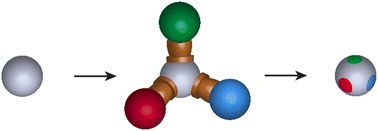
In order to create micron-sized particles with several dissimilar patches, we translated this strategy by using colloidal particles coated with DNA inks as stamps. The colloidal stamps can assemble with support colloids via DNA hybridization. The injection of eject strands allowed us to transfer the DNA inks at the contact zones between the support and stamp particles (Fig. 1a) leading to patchy particles. We also took advantage of packing constraints to control the number of stamp particles that can park around support particles,5a which finally defines the number of transferred patches.


image file: d2nr05016a-f1.tif
Fig. 1 General scheme and key steps. (a) General schematic representation of the preparation of particles with DNA patches by colloidal stamping following sequentially the subsequent steps. (b) Inking: the ink, formed by the association of T–X–A* and X*–B*, is hybridized at the surface of the bare stamp particle decorated with an A* DNA brush. (c) Assembly: in the contact zone, formation of duplexes between the support particle decorated by B strands and the stamp thanks to the B* domain exposed by the ink. (d) Passivation: the surface of the support particle, outside of the contact zone is passivated by hybridization between the B strands of the surface and Y*–B* strands. (e) Eject: strand displacement reaction to separate the stamp from the support particle, leading to the formation of an X*–B* patch at the contact zone and the recovery of patchy particles exposing the stand Y* on the surface with patches of X*. (f) Schematic representation of the DNA strands and assemblies used in this study.

Experimental

Synthesis of DNA-coated particles

Azidated 3-(trimethoxysilyl)propyl methacrylate (TPM) particles were prepared through the azidation of chlorine groups present at the surface of particles previously synthesized according to the protocol developed by Wang et al.6e (see the ESI). After synthesis the particles were imaged by TEM and SEM. Fig. S1 shows that they are spherical and monodisperse in size. Their surface is smooth, which has been shown to be required to allow homogeneous distribution of DNA strands during the former step.13 In order to functionalize monodisperse polystyrene (PS) particles with azide groups, we followed the protocol developed by Oh et al.,6d which relies on the physical entrapment of an azidated PS-b-PEO copolymer (PS-b-PEO-N3). For this, the PS particles are swollen with tetrahydrofuran (THF) to allow the PS block of the copolymer to penetrate the PS particles (see the ESI). After the evaporation of THF, the PS block of the copolymer is physically trapped in the PS particles while the PEO block and the terminal azide group form a brush at the surface, swollen by water and exposed to the surrounding media. Azidated particles were further functionalized with DNA following the protocol described by Wang et al.6e that ensures a dense surface coverage of the colloids with DNA (see the ESI). The process relies on the strain-promoted azide–alkyne cycloaddition (SPAAC) to graft DNA strands end-functionalized with a dibenzocyclooctyne moiety (DBCO) onto azide functionalized particles.

Characterization

Transmission electron microscopy (TEM) images were taken using a Hitachi H600 microscope operating at an acceleration voltage of 75 kV. The samples for TEM observation were supported on conventional carbon-coated copper grids. Scanning electron microscopy (SEM) images were taken using a Hitachi S4500 microscope at an accelerating voltage of 5 kV. Confocal fluorescence microscopy images were taken using a Leica SP2 confocal laser scanning microscope as well as a ZEISS LSM980 equipped with an Airyscan detector.

Results and discussion

DNA strands A and B (Table S1) have first been grafted onto azidated TPM and PS particles, respectively. The coated particles are referred to as TPMA and PSB. We then functionalized/inked the stamp TPMA particles with the Ink565 (see Table S1 for details) by adding a large excess of ink to a suspension of particles (Fig. 1b). The ink consists of two hybridized DNA strands, T–X–A* and X*565–B*, the latter being modified with the fluorescent dye Atto565. As the domain A* is complementary to sequence A at the surface of the TPM particles, the ink sticks to their surface due to the formation of A/A* duplexes. The particles and strands were maintained in a buffer enriched in magnesium ions at low temperature in order to strengthen the DNA duplexes and prevent strand migration (see ESI). Excess ink was subsequently washed away by centrifugation/dispersion steps. As Ink565 is also complementary to strands B, the TPMA ∼ Ink565 stamp particles were mixed with a 40[thin space (1/6-em)]:[thin space (1/6-em)]1 excess of PSB particles to form preferentially small clusters with only one TPMA particle at the core and PSB satellites (Fig. 1c). This ultimately maximizes the number of one-patch PS particles produced in the process. When the assembly is completed, Y*488–B* strands (labelled with Alexa488) are added to hybridize with the remaining B strands available on the PSB particles and passivate their surface (Fig. 1d). Fig. 2a shows that clusters made of one TPMA particle surrounded by PSB particles were obtained. A detailed analysis reveals that the number of PSB particles in the clusters varies from 1 to 7. Their relative amounts have been determined by a statistical analysis performed over 100 clusters (Fig. 2c–i). Some rare clusters (∼5%) formed from one PSB particle in contact with two TPMA particles could be observed as well as a large amount of free PSA particles. Thanks to the density difference between TPM (1.2 g cm−3 (ref. 14)) and PS (1.06 g cm−3), we successfully removed most of these free PS particles (Fig. 2b) by sedimentation in a PBS-based buffer solution of intermediate density (1.07 g cm−3) prepared by mixing H2O and D2O (see ESI). The relative proportions of different clusters remained unchanged during this purification stage, as indicated in Fig. 2c–i, proving that the clusters are sufficiently robust and do not break during centrifugation. The final step to form patchy particles consists of disassembling the clusters formed by the stamp and support particles leaving the fluorescent part of the ink on the support particle only at the contact point between them. To do so, we injected the EjectX strand, which binds to the toehold T of Ink565 and replaces the strand X*565–B*. This breaks the duplex X/X* that was holding the stamp and support particles and results in the release of the support particle, which still carries the red fluorescent strands X*565–B* at the former contact point with the stamp (Fig. 1e and S2). Fig. 2j and Movie S1 show that PS particles with one red fluorescent patch are mostly obtained, validating the developed strategy.
image file: d2nr05016a-f2.tif
Fig. 2 Confocal fluorescence microscopy images of clusters obtained by incubating 1.6 μm TPMA ∼ Ink565 and 1.5 μm PSB particles in a 1[thin space (1/6-em)]:[thin space (1/6-em)]40 ratio (a) before and (b) after purification. (c)–(i) Zoom images of the different clusters containing 1 to 7 PS particles. Their relative amounts (in %) in the sample before/after purification are given at the top right corner of each image. (j) Confocal fluorescence microscopy image of the patchy PS particles resulting from the strand-displacement disassembly of TPMA ∼ Ink565 ∼ PSB clusters. Scale bar of 10 μm for (a), (b) and (j), and 5 μm for (c) to (i).

Some non-patchy PS particles that were not completely removed by centrifugation, and a few two-patch particles (∼5%), which result from the disassembly of the clusters in which one PS particle is in contact with two TPM particles, are also observed.

We firstly extended our strategy to prepare particles with multiple identical patches precisely located at their surface. To do so, we prepared clusters with different controlled morphologies by the random parking5a of an excess of large PS spheres functionalized with DNA strands A and Ink565 on smaller TPM particles functionalized with DNA strands B. Due to packing constraints inherent in the ratio of radii between large and small spheres, only a fixed number of large spheres can park, leading to a population of clusters with a well-defined coordination. When the assembly is completed, the Y*488–B* strands, complementary to DNA strands B, are added to passivate the surface of TPMB particles. Fig. 3a–c show confocal images of the DNA-colloidal clusters obtained when TPM particles with diameters of 1.1, 1.6, and 2 μm are employed, respectively. Different clusters made of one TPM core and different numbers of PS satellites are observed (Fig. 3d–g and S3). The relative proportions of each type of cluster obtained for different values of the size ratio α of PS/TPM, are listed in Table 1. One can note that when α is 4.39, clusters made of one or two PS particles attached to one TPM sphere are mainly formed. Decreasing α to 3.02 and 2.42 led to the formation of higher proportions of clusters containing 3 and 4 PS particles, as expected.


image file: d2nr05016a-f3.tif
Fig. 3 Confocal fluorescence microscopy images of the clusters obtained by incubating TPMB and PSA ∼ Ink565 in a 1[thin space (1/6-em)]:[thin space (1/6-em)]40 ratio followed by the addition of the Y*488–B* passivation strand. The diameters of TPM particles are: (a) 1.1 μm (α = 4.39), (b) and (d)–(g) 1.6 μm (α = 3.02), and (c) 2 μm (α = 2.42). (h) Confocal fluorescence microscopy image (Alexa488, green channel; Atto565, red channel) with transmission microscopy (grey channel) of PSA ∼ Ink565 ∼ TPMB and Y*488–B* (α = 3.02) clusters after the strand-displacement reaction using the EjectX strand. (i)–(l) Zoom images of the patchy TPM particles with an increasing number of patches obtained after the strand-displacement reaction using EjectX (α = 3.02). Scale bar of 10 μm for (a) to (h) and 2 μm for (i) to (l).
Table 1 Compositions of the batches resulting from the mixing of TPMB of different sizes with PSA ∼ Ink565 in a 1[thin space (1/6-em)]:[thin space (1/6-em)]40 number ratio determined by statistical analysis of confocal fluorescence images over about 100 clusters
α

image file: d2nr05016a-u1.tif

image file: d2nr05016a-u2.tif

image file: d2nr05016a-u3.tif

image file: d2nr05016a-u4.tif

image file: d2nr05016a-u5.tif

4.39 3 39 50 8 0
3.02 0 20 29 44 7
2.42 0 3 27 39 31


After the injection of the eject strands EjectX in the cluster suspension, non-fluorescent PS particles and TPM particles with red fluorescent patches are observed, proving the transfer of the fluorescent DNA from PSA ∼ Ink565 (Fig. 3h and S3). More precisely, Fig. 3i–l show that 1.6 μm TPM particles with one to four patches are obtained. Similar results were obtained with 1.1 μm and 2 μm TPM particles (Fig. S5), validating the strategy based on the combination of colloidal parking and colloidal stamping.

Finally, we further extended our strategy to prepare particles with multiple dissimilar patches. We first divided the PS particles into two batches, and coated one batch with Ink565 and the other with Ink647 (Table S1). The two batches were then mixed together and TPMB particles functionalized with B strands were added in a number ratio TPMB[thin space (1/6-em)]:[thin space (1/6-em)]PSA ∼ Ink565[thin space (1/6-em)]:[thin space (1/6-em)]PSA ∼ Ink647 of 1[thin space (1/6-em)]:[thin space (1/6-em)]20[thin space (1/6-em)]:[thin space (1/6-em)]20. The sample was kept in the fridge at 4 °C for 24 h to maximize the formation of clusters. Then, Y*488–B* strands were added to hybridize with the B strands outside the contact zones and passivate the surface of the TPMB particles.

Different clusters made of one TPM core and different numbers of PSA ∼ Ink565 and PSA ∼ Ink647 are observed (Fig. 4a–j). The relative proportions of each type of cluster are listed in Table 2. After injection of the eject strands EjectX and EjectZ in the suspension of clusters, non-fluorescent PS particles and TPM particles with red and/or blue fluorescent patches are observed, proving the transfer of the fluorescent DNA from PSA ∼ Ink565 and PSA ∼ Ink647 (Fig. 4k and S6 and Movie S2). When we worked with three batches of PSA particles coated with Ink488, Ink565 and Ink647, respectively, and mixed them with TPMB particles in a number ratio TPMB[thin space (1/6-em)]:[thin space (1/6-em)]PSA ∼ Ink488[thin space (1/6-em)]:[thin space (1/6-em)]PSA ∼ Ink565[thin space (1/6-em)]:[thin space (1/6-em)]PSA ∼ Ink647 of 1[thin space (1/6-em)]:[thin space (1/6-em)]13[thin space (1/6-em)]:[thin space (1/6-em)]13[thin space (1/6-em)]:[thin space (1/6-em)]13, we observed the formation of a few clusters made of one TPM particle surrounded by varying numbers of PSA ∼ Ink488, PSA ∼ Ink565 and PSA ∼ Ink647 particles (Fig. 4l). After the injection of EjectX, EjectY and EjectZ, TPM particles with red and/or blue and/or green fluorescent patches are observed, proving once again the efficiency of our approach (Fig. 4m and Movie S3).


image file: d2nr05016a-f4.tif
Fig. 4 Confocal fluorescence microscopy images (a–j) of the clusters obtained by incubating TPMB, PSA ∼ Ink565 and PSA ∼ Ink647 in a 1[thin space (1/6-em)]:[thin space (1/6-em)]20[thin space (1/6-em)]:[thin space (1/6-em)]20 number ratio followed by the addition of the passivation strand Y*488–B*. The diameter of the TPM particles is 1.6 μm (α = 3.02). (k) Confocal fluorescence microscopy image of the patchy particles obtained after injection of EjectX and EjectZ. The inset shows a TPM particle with one red and one blue fluorescent patch. (l) Confocal fluorescence microscopy image of a cluster made of one TPM particle surrounded by one PSA ∼ Ink488, one PSA ∼ Ink565 and one PSA ∼ Ink647 particle. (m) Confocal fluorescence microscopy image of the patchy 1.6 μm TPM particles obtained after injection of EjectX, EjectY and EjectZ. Scale bar of 10 μm for (a), 5 μm for (b) to (m), and 2 μm for (k) in the inset.
Table 2 Compositions of the batches resulting from the mixing of TPMB with PSA ∼ Ink565 and PSA ∼ Ink647 in a 1[thin space (1/6-em)]:[thin space (1/6-em)]20[thin space (1/6-em)]:[thin space (1/6-em)]20 number ratio determined by statistical analysis of confocal fluorescence images over about 100 clusters
image file: d2nr05016a-u6.tif image file: d2nr05016a-u7.tif image file: d2nr05016a-u8.tif image file: d2nr05016a-u9.tif image file: d2nr05016a-u10.tif image file: d2nr05016a-u11.tif image file: d2nr05016a-u12.tif image file: d2nr05016a-u13.tif image file: d2nr05016a-u14.tif image file: d2nr05016a-u15.tif
7 22 26 8 19 13 0 2 2 1


Conclusions

In conclusion, we have synthesized micron-sized particles with one or several identical and distinct DNA patches by combining colloidal parking and the transfer of DNA strands at the contact zones with colloidal stamps thanks to strand-displacement reactions. Our strategy is versatile and can be extended to a gallery of hard particles and soft systems whose shape and size could be independently varied, opening the way to the synthesis of new DNA-patchy building blocks and the comprehensive study of their assembly into novel structures, such as alternating polymers or rings, dendrimers or gyroid crystals.

Author contributions

R. Mérindol, E. Ducrot and S. Ravaine conceived this research. R. Mérindol and E. Ducrot designed the experimental process and revised the manuscript. R. Khalaf performed most of the experiments. A. Viamonte helped R. Khalaf to perform some of the experiments. R. Khalaf, E. Ducrot and S. Ravaine performed data analysis. S. Ravaine wrote the manuscript.

Conflicts of interest

There are no conflicts to declare.

Acknowledgements

The authors thank S. Yao and I.-S. Jo for the functionalization of the copolymer. R. Khalaf thanks the French Ministry of Higher Education, Research and Innovation and Campus France for her PhD grant. This work was supported by the Agence Nationale de la Recherche (POESY project, ANR-18-CE09-0019). We acknowledge funding from IdEx Bordeaux, a program of the French government managed by the Agence Nationale de la Recherche (ANR-10-IDEX-03-02), and Région Nouvelle-Aquitaine (AAPR 2020-2019-8330510).

References

  1. (a) X. Bouju, E. Duguet, F. Gauffre, C. R. Henry, M. L. Kahn, P. Mélinon and S. Ravaine, Adv. Mater., 2018, 30, 1706558 CrossRef PubMed; (b) G. M. Whitesides and M. Boncheva, Proc. Natl. Acad. Sci. U. S. A., 2002, 99, 4769–4774 CrossRef CAS PubMed; (c) D. Frenkel, Science, 2002, 296, 65–66 CrossRef CAS PubMed.
  2. (a) R. Mérindol, E. Duguet and S. Ravaine, Chem. – Asian J., 2019, 14, 3232–3239 CrossRef PubMed; (b) W. Li, H. Palis, R. Mérindol, J. Majimel, S. Ravaine and E. Duguet, Chem. Soc. Rev., 2020, 49, 1955–1976 RSC.
  3. (a) H. Zheng and S. Ravaine, Crystals, 2016, 6, 54 CrossRef; (b) Z. Cai, Z. Li, S. Ravaine, M. He, Y. Song, Y. Yin, H. Zheng, J. Teng and A. Zhang, Chem. Soc. Rev., 2021, 50, 5898–5951 RSC.
  4. E. Elacqua, X. Zheng, C. Shillingford, M. Liu and M. Weck, Acc. Chem. Res., 2017, 50, 2756–2766 CrossRef CAS PubMed.
  5. (a) N. B. Schade, M. C. Holmes-Cerfon, E. R. Chen, D. Aronzon, J. W. Collins, J. A. Fan, F. Capasso and V. N. Manoharan, Phys. Rev. Lett., 2013, 110, 148303 CrossRef PubMed; (b) K.-T. Wu, L. Feng, R. Sha, R. Dreyfus, A. Y. Grosberg, N. C. Seeman and P. M. Chaikin, Proc. Natl. Acad. Sci. U. S. A., 2012, 109, 18731–18736 CrossRef CAS PubMed; (c) M. Dwivedi, S. L. Singh, A. S. Bharadwaj, V. Kishore and A. V. Singh, Micromachines, 2022, 13, 1102 CrossRef PubMed; (d) J. Lowensohn, B. Oyarzún, G. N. Paliza, B. M. Mognetti and W. B. Rogers, Phys. Rev. X, 2019, 9, 041054 CAS.
  6. (a) N. Geerts and E. Eiser, Soft Matter, 2010, 6, 4647–4660 RSC; (b) W. B. Rogers, W. M. Shih and V. N. Manoharan, Nat. Rev. Mater., 2016, 1, 16008 CrossRef CAS; (c) J. T. McGinley, I. Jenkins, T. Sinno and J. C. Crocker, Soft Matter, 2013, 9, 9119–9128 RSC; (d) J. S. Oh, Y. Wang, D. J. Pine and G.-R. Yi, Chem. Mater., 2015, 27, 8337–8344 CrossRef CAS; (e) Y. Wang, Y. Wang, X. Zheng, É. Ducrot, M.-G. Lee, G.-R. Yi, M. Weck and D. J. Pine, J. Am. Chem. Soc., 2015, 137, 10760–10766 CrossRef CAS PubMed.
  7. (a) X. Zheng, Y. Wang, Y. Wang, D. J. Pine and M. Weck, Chem. Mater., 2016, 28, 3984–3989 CrossRef CAS; (b) Y. Wang, Y. Wang, D. R. Breed, V. N. Manoharan, L. Feng, A. D. Hollingsworth, M. Weck and D. J. Pine, Nature, 2012, 491, 51–56 CrossRef CAS PubMed; (c) L. Feng, R. Dreyfus, R. Sha, N. C. Seeman and P. M. Chaikin, Adv. Mater., 2013, 25, 2779–2783 CrossRef CAS PubMed; (d) G. Yao, J. Li, Q. Li, X. Chen, X. Liu, F. Wang, Z. Qu, Z. Ge, R. P. Narayanan, D. Williams, H. Pei, X. Zuo, L. Wang, H. Yan, B. L. Feringa and C. Fan, Nat. Mater., 2020, 19, 781–788 CrossRef CAS PubMed; (e) S. Ravaine and E. Duguet, Curr. Opin. Colloid Interface Sci., 2017, 30, 45–53 CrossRef CAS; (f) E. Duguet, C. Hubert, C. Chomette, A. Perro and S. Ravaine, C. R. Chim., 2016, 19, 173–182 CrossRef CAS; (g) M. Y. Ben Zion, X. He, C. C. Maass, R. Sha, N. C. Seeman and P. M. Chaikin, Science, 2017, 358, 633–636 CrossRef CAS PubMed; (h) Y. Zhang, X. He, R. Zhuo, R. Sha, J. Brujic, N. C. Seeman and P. M. Chaikin, Proc. Natl. Acad. Sci. U. S. A., 2018, 115, 9086–9091 CrossRef CAS PubMed; (i) J. A. Diaz A, J.-S. Oh, G.-R. Yi and D. J. Pine, Proc. Natl. Acad. Sci. U. S. A., 2020, 117, 10645–10653 CrossRef PubMed.
  8. T. G. W. Edwardson, K. L. Lau, D. Bousmail, C. J. Serpell and H. F. Sleiman, Nat. Chem., 2016, 8, 162–170 CrossRef CAS PubMed.
  9. T. Trinh, C. Liao, V. Toader, M. Barłóg, H. S. Bazzi, J. Li and H. F. Sleiman, Nat. Chem., 2018, 10, 184–192 CrossRef CAS PubMed.
  10. Y. Zhang, J. Chao, H. Liu, F. Wang, S. Su, B. Liu, L. Zhan, J. Shi, L. Wang, W. Huang, L. Wang and C. Fan, Angew. Chem., Int. Ed., 2016, 55, 8036–8040 CrossRef CAS PubMed.
  11. Y. Xiong, S. Yang, Y. Tian, A. Michelson, S. Xiang, H. Xin and O. Gang, ACS Nano, 2020, 14, 6823–6833 CrossRef CAS PubMed.
  12. E. W. Gehrels, W. B. Rogers and V. N. Manoharan, Soft Matter, 2018, 14, 969–984 RSC.
  13. Y. Wang, Y. Wang, X. Zheng, É. Ducrot, J. S. Yodh, M. Weck and D. J. Pine, Nat. Commun., 2015, 6, 7253 CrossRef CAS PubMed.
  14. C. van der Wel, R. K. Bhan, R. W. Verweij, H. C. Frijters, Z. Gong, A. D. Hollingsworth, S. Sacanna and D. J. Kraft, Langmuir, 2017, 33, 8174–8180 CrossRef CAS PubMed.

Footnotes

Electronic supplementary information (ESI) available: Materials, methods, synthesis of DNA-coated TPM and PS particles, and characterization techniques. See DOI: https://doi.org/10.1039/d2nr05016a
Present address: Department of Chemistry, An-Najah National University, Nablus, Palestine.

This journal is © The Royal Society of Chemistry 2023