
Construction of a scalable DNA computing nano-system for large-scale and complex logical operations†
Chunyang
Zhou
 a,
Yiwei
Song
a,
Xiuyan
Jin
a,
Bei
Li
*bc and
Chunying
Pang
*a
a,
Yiwei
Song
a,
Xiuyan
Jin
a,
Bei
Li
*bc and
Chunying
Pang
*a
aBiomedical Engineering, School of Life Science and Technology, Changchun University of Science and Technology, Changchun, 130031, China. E-mail: 1281957328@qq.com
bChangchun Institute of Optics, Precision Machinery and Physics, Chinese Academy of Sciences, Changchun, 130031, China. E-mail: beili@ciomp.ac.cn
cUniversity of Chinese Academy of Sciences, Beijing 100049, China
First published on 7th December 2022
Abstract
The predictability of Watson–Crick base pairing provides unique structural programmability to DNA, facilitating the development and application of biomolecules in biocomputing. However, in DNA-based biocomputing, the scale of operation that can be achieved by an existing reaction system is very limited. How to expand the operation range of a logic circuit and realize the integration and extensibility of circuits is always the key problem to be solved in this field. In this work, by designing a multifunctional DNA–nanostructure-based reaction platform, which can realize an output of up to 2n scalable fluorescence signals, combined with the construction of an input “library” and a modular distribution strategy of output signals, for the first time, we successfully performed the calculation of both square roots and cube roots of consecutive integers within a decimal number of “10” and in each result of the operation, two digits after the decimal point are preserved (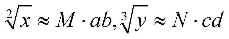 ). We believe that the design concept presented in this work can help effectively solve the urgent problems of biological computing in terms of computational scaling, integration and scalability, and can open up new horizons for the design of new functional devices and complex computing circuits.
New conceptsOver the past decade or so, biochemical approaches based on nucleic acid molecules have been shown to be successful in solving computer problems. However, the logic gates designed in the present study are relatively simple. When multiple logic gates are required, how to find a suitable pair of fluorescence FRET without overlapping each other may be a difficult problem to solve. Also, the bottleneck for further development in this field is how to construct complex logic circuits to expand the scope of computation, to realize the integration and scalability of circuits, and further promote the completion of larger scale logic circuits. This work overcomes the problem that the fluorescence output channel cannot be improved due to the limitation of the types of fluorescence signals modified on DNA strands (generally no more than 10, and the emission peaks overlap, making it difficult to distinguish and extract the signals). Based on this, the strategy successfully extracts up to 2n fluorescence output channels from the reaction solution, and it is scalable. Furthermore, this work successfully realized the calculation of both square roots and cube roots of consecutive integers within a decimal number of “10”, and in each result of operation, two digits after the decimal point are preserved ( ). This is by far the most computationally complex logical operation with the largest scale of output channels in DNA-based biological computing. ). This is by far the most computationally complex logical operation with the largest scale of output channels in DNA-based biological computing.
|
1 Introduction
DNA computing is an emerging interdisciplinary subject developed on the basis of computational science and molecular biology, and is a promising alternative to biological computing.1–4 With great storage density and high parallelism, DNA computing provides a new method to solve complex combinatorial optimization problems, such as NP-complete problems, opening up a broad application prospect.5,6 With the boom in the DNA nanotechnology pioneered by Ned Seeman, DNA is no longer thought of as a pure carrier of genetic codes, and has emerged as a fine engineering material for logical computation because of its specific base-pairing properties,7–9 which makes it possible to construct DNA circuits for complex tasks. Up to now, various basic and advanced DNA-based logic gates have been reported, especially for implementing specific arithmetic functions, non-arithmetic information processing, general cascaded/concatenated logic circuits, non-Boolean logic, etc.10–16 However, the bottleneck for further development in this field is how to construct complex logic circuits to expand the scope of computation, realize the integration and scalability of circuits, and further promote the completion of larger-scale logic circuits.10To get to the root of the problem, we try to explore the causes of the three basic components of DNA computing, including the coding of the solution, the processing of information through molecular interactions, and the extraction of the output signal after processing. Based on long-term experimental experience and literature analysis in this field, we summarize the following three reasons limiting the development of large-scale DNA computing. First, coding input DNA for increasing the scale of parallel computing is limited. The amount of DNA involved in encoding and the number of bases per DNA sequence directly affect the encoding efficiency. In the currently used DNA logic gates, there is usually only one DNA sequence encoded in each input channel.17–20 In addition, due to the limitation of synthesis technology, an excessive number of DNA bases lead to a reduction of purity and an increase in errors, which significantly limit the encoding range of DNA involved in the reaction and the scale of parallel computation. Second, the limitation of building a powerful reaction platform adapted to the large number of input signals used in highly parallel computing, as described above. The three basic components of DNA computing are interconnected, so an increase in the coding range of the input signal at the upper level requires a corresponding increase in the function of the reaction platform at the lower level. The third limitation is the specific recognition of large-scale output signals for the extraction of solutions. As the input becomes larger and the response platform becomes more powerful, the corresponding large-scale identifiable output signal is needed to extract the results obtained by the logic operation. However, the scale of the output signal that can be achieved is currently limited, usually no more than 5-bit binary digits.10–16
In order to overcome the limitations mentioned above and realize large-scale complex logic circuits, this work is devoted to the following three aspects of improvement. First of all, a DNA sequence “library” is constructed to support multi-channel signal input, replacing the traditional single-stranded DNA input mode. This improvement greatly increases the encoding capacity of the input DNA and provides a more flexible and large addressable range for downstream reaction platforms. In addition, because of DNA's powerful base-pairing properties and structural stability, the chain number of a DNA library can increase linearly or nonlinearly with an increase in the complexity of the solving problem. Second, in order to satisfy the increasing coding capacity of input DNA, a multi-component, multi-functional and highly stable DNA–nanostructure-based system is constructed as a reaction platform for large-scale complex logic operations. On the basis of our previous research,10,11 the scale of the reaction platform is enlarged in this work, and the range of molecular interactions is further increased. In this reaction system, each DNA–nanostructure monomer can provide up to six coding sites (Fig. S1, ESI†) with high parallelism and scalability. Therefore, such an improved reaction platform can not only be applied to a large-scale signal input and its encoding, but can also be enlarged with an increase in input capacity. Third, modular division of output fluorescence signals is carried out. The aim of this strategy is to overcome the problem that the fluorescence output channel cannot be improved due to the limitation of the types of fluorescence signals modified on DNA strands (generally no more than 10, and the emission peaks overlap, making it difficult to distinguish and extract the signals). Based on this, the strategy successfully extracts up to 2n fluorescence output channels from the reaction solution, and it is scalable.
Based on the above strategy, in this work, depending on the same reaction system, we successfully realize the calculation of both the square roots and cube roots of consecutive integers within a decimal number of “10”, and in each result of the operation, two digits after the decimal point are preserved ( ). This is by far the most computationally complex logical operation with the largest scale of output channels in DNA-based biological computing.
2 Methods
2.1 Chemicals and apparatus
The DNAs used in this work were synthesized by Sangon Biotechnology Company (Shanghai, China) and are listed in Tables S1–S3 (ESI†). All the DNAs were dissolved in distilled water and quantified using a Nanodrop One system from Thermo with the following extinction coefficients (ε260![[thin space (1/6-em)]](https://www.rsc.org/images/entities/char_2009.gif) nm, m−1 cm−1): A = 15400, G = 11500, C = 7400, T = 8700. The chemicals acrylamide, ammonium persulfate, tris(hydroxymethyl) aminomethane, and boric acid used in the experiment were purchased from Aladdin Biochemical Technology Co. LTD. Ethylene diamine tetra acetic acid (EDTA) was purchased from Sangon Biotechnology Company. All chemicals used were of analytical grade were used without further purification. All solutions were prepared using ultrapure water (18.2 MΩ cm) obtained from a Milli-Q purification system. The DNAs were diluted with tris–HCl buffer (20 × 10−3 M Tris–HCl, 200 × 10−3 M KCl, and 10 × 10−3 M MgCl2, pH 8.0) before use in the logic operation. The native polyacrylamide gel electrophoresis experiments were performed using an electrophoresis tank from Bio Rad. The gel images were obtained using a BioDoc-It2 imager from UVP. The fluorescence emission spectra were collected using an Agilent Microplate reader.
nm, m−1 cm−1): A = 15400, G = 11500, C = 7400, T = 8700. The chemicals acrylamide, ammonium persulfate, tris(hydroxymethyl) aminomethane, and boric acid used in the experiment were purchased from Aladdin Biochemical Technology Co. LTD. Ethylene diamine tetra acetic acid (EDTA) was purchased from Sangon Biotechnology Company. All chemicals used were of analytical grade were used without further purification. All solutions were prepared using ultrapure water (18.2 MΩ cm) obtained from a Milli-Q purification system. The DNAs were diluted with tris–HCl buffer (20 × 10−3 M Tris–HCl, 200 × 10−3 M KCl, and 10 × 10−3 M MgCl2, pH 8.0) before use in the logic operation. The native polyacrylamide gel electrophoresis experiments were performed using an electrophoresis tank from Bio Rad. The gel images were obtained using a BioDoc-It2 imager from UVP. The fluorescence emission spectra were collected using an Agilent Microplate reader.
2.2 Fluorescence measurement
The fluorescence emission spectra of the output were collected in Tris–HCl buffer (20 × 10−3 M Tris–HCl, 200 × 10−3 M KCl, and 10 × 10−3 M MgCl2, pH 8.0) at room temperature. The emission spectra of FAM were collected from 500 to 560 nm with an excitation wavelength of 494 nm and the slit widths for excitation and emission were all 10 nm. The emission spectra of HEX were collected from 545 to 575 nm with an excitation wavelength of 535 nm and the slit widths for excitation and emission were all 10 nm.2.3 Native polyacrylamide gel electrophoresis
Before use, the DNA solutions were heated at 90 °C for 10 min and slowly cooled down to room temperature. Then, a mixture of platforms and corresponding inputs was added to the final volume of 100 μL and incubated for 60 min. A 15% native polyacrylamide gel was prepared and electrophoresis was conducted in 1× TBE buffer (17.8 × 10⁻³ M boric acid, 17.8 × 10⁻³ M Tris, 2 × 10⁻³ M EDTA, pH 8.0) at a constant voltage of 80 V for about 2 h. Then, the finished gels were scanned using a UV transilluminator.2.4 Operation of square root and cube root logic circuits
The optimized DNA–nanostructure-based platform (P1–P10) that was evenly distributed in five centrifuge tubes was used as the universal system for the operation of 10-bit-output square root and cube root logic circuits. Different DNA strand solutions were heated at 90 °C for about 10 min and slowly cooled down to room temperature. According to the truth table, the input sequences used for one calculation were mixed in advance and the mixture was then added in equal quantities to five centrifuge tubes containing the reaction platform. After about an hour of reaction, all the solution to be tested was transferred into a 96-well plate, and the output signal was tested quickly and efficiently with a microplate reader. The optimized concentrations of inputs and DNA-based platform were mixed to a final volume of 100 μL.3 Results and discussion
Since the invention of the algebraic system of logic by George Boole in the middle of the 19th century, “Boolean logic operation” has been established by using binary numbers to carry out logical operations, assigning “1” to “true” and “0” to “false”.21 Logic gates are basic components that are used to perform Boolean logic operations (logic circuits), which include three basic types: AND gate, OR gate and NOT gate. By controlling the high and low voltages of the inputs (representing the logical “true” and “false” or “1” and “0” in binary, respectively), the logic gate is triggered to generate corresponding binary output signals (“0” or “1”), thus realizing the logical operation. Similar to electronic computation, in biocomputation, molecular logic gates use binary-encoded molecules as inputs (“1” for presence and “0” for absence) and optical/electrochemical signals as outputs (“1” for high and “0” for low).22–26 For a given logical function to be calculated, the logical relationship between its input variables and output variables should be described in a table in the binary language in advance, which is called a truth table.27 Then, the corresponding logical circuit diagram is drawn according to the distribution of the truth table. Based on this, the operator then begins to encode the input signal of the logic circuit, construct the reaction platform and encode the interaction between it and the input signal, and finally collect the output signal for the extraction of solutions. In this work, in order to perform large-scale complex logic calculations with 4-bit input and 10-bit output square roots and cube roots, while satisfying the requirement that the result of calculation is reported to two digits after the decimal point ( ), the corresponding two truth tables should be defined first of all (Fig. 1).
 | ||
| Fig. 1 Definition of truth tables for 4-bit-input/10-bit-output square root and cube root calculation. The output signals are modularized into three parts, respectively representing the integer bit, first digit behind the decimal point, and second digit behind the decimal point in the decimal calculation result. | ||
As shown in Fig. 1, the logical calculation ranges of square roots and cube roots are chosen to be any integer in the range “1 ≤ x ≤ 10” (or “1 ≤ y ≤ 10”), and the result value is reported up to two digits after the decimal point. The truth table begins with the conversion of the digits to be taken square root (decimal number) into a 4-bit binary number, which is used as input signals. The results of the computation reported to two digits after the decimal point (decimal number) are then converted to a 10-bit binary number, which is used as an output signal. Finally, according to the distribution position of the digits before and after the decimal point in the calculation result, the 10-bit output binary numbers are modularly divided into three parts, namely, the calculated integer bit of the decimal fraction (the decimal number of “M” corresponds to two binary numbers of “Y1” and “Y2”), the first digit after the decimal point (decimal number of “a” corresponds to four binary numbers of “Y3”, “Y4”, “Y5” and “Y6”), and the second digit after the decimal point (decimal number of “b” corresponds to four binary numbers of “Y7”, “Y8”, “Y9” and “Y10”) in sequence.
In the next step, relying on the powerful DNA hybridization and toehold-mediated DNA strand displacement (TDSD), a multi-functional reaction platform capable of implementing both square root calculation and cube root calculation needs to be constructed. The reaction platform is similar to the “central processing unit” of a traditional computer, which can read input instructions and perform certain operations on them (DNA hybridization or chain displacement reaction), and then release the signal as output for subsequent analysis. For complex biological computations, including the computing system in this work, the output scale of which is up to 10-bit binary digits, usually requires 10 fluorescent dyes with different emission peaks as output signal markers for detection and recognition. However, limited by the current development of science and technology, it is difficult to find 10 kinds of fluorescent output dyes that meet the conditions, which is also one of the difficulties faced in biocomputing in the expansion of the computing scale.
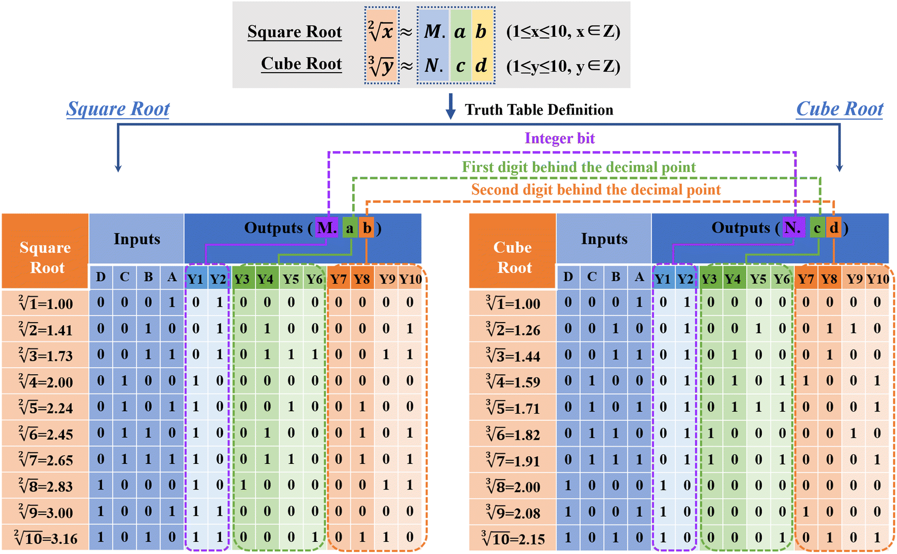
In order to overcome this problem, we construct a set of ten DNA–nanostructure-based monomers (P1–P10) as the reaction platform for this work, and evenly distributed these ten monomers in five tubes in turn, so that each pair of two monomers modified with different fluorescence signals (FAM and HEX) is divided into a subset, as shown in Fig. 2(a). Each monomer is composed of three DNA single strands, and two of the strands are modified with fluorescence groups and quenching groups, which hybridize with the third single strand. Based on this, the corresponding ten output signals are spatially isolated into five independent subsets too. Combined with the loading reaction platform of a 96-well plate and signal acquisition of a microplate reader, the multi-channel, high-efficiency, and distinguishable detection of the ten output signals labeled with only two fluorescent dyes is realized. The reaction system shows good scalability, which can be further expanded by increasing the channel of the reaction base and the corresponding encoded DNA input into the library. Also, the complexity of calculation can be overcome by directly increasing the number of reaction monomers and centrifuge the tubes arranged in parallel, and finally, an output scale of logic operation up to 2n can be realized. Although in this work we have accomplished an operation output scale of n = 5, in the subsequent research, we will continue to study in depth, aiming at achieving the complex logic operations with larger output.
 | ||
| Fig. 2 (a) Description of the construction of the reaction platform, which can be used to calculate both square root and cube root logic operations. The reaction platform is a combination of ten DNA-nanostructure-based monomers (P1–P10), which are successively separated into five tubes periodically with two different fluorescence (FAM and HEX). (b) Construction of an input DNA library for the logical operation of square roots. (c) Reaction mechanism of P1–P10 monomers in the platform. The fluorescence signal can be enhanced by hybridization with any of the active sites on the monomer. (d) Changes in the fluorescence intensity of ten monomers before and after adding the input sequence that can react with them. (e) Structural integrity of the synthetic DNA–nanostructure monomer is further demonstrated by a PAGE experiment. Taking the formation of P1 monomers as an example, P-1, Q-1, and F-1 are single-stranded DNA respectively, and their band positions are shown in Fig. 2(e). When they were mixed together and reacted for 1 hour, a band at P1 position was formed, indicating that the three single-stranded DNA had undergone sufficient hybridization reaction. | ||
The reaction mechanism of P1–P10 monomers in the reaction platform is shown in Fig. 2(c). The optimized concentrations of three single-stranded DNAs that consist of each DNA–nanostructure-based monomer has been discussed in Fig. S2 (ESI†). By editing the chain replacement hybridization reaction between the input and the reaction platform, the quenched fluorescence signal on the reaction platform can be effectively turned on. As shown in Fig. 2(d), changes in fluorescence intensity of ten monomers before and after adding the input sequence that can react with them are respectively shown, which proves that the reaction platform performs very well and has a very low background signal. In addition, we further prove that when ten monomers are divided into five subsets, each subset can still maintain an ideal fluorescence switching effect and a low background signal (Fig. S3, ESI†). As shown in Fig. 2(e), we further demonstrated the structural integrity of the synthetic DNA–nanostructure monomer by a PAGE experiment. Due to the short sequence of Q-DNA, the bands cannot be reflected in the PAGE.
The design rules of the reaction platform are closely related to the construction of input sequences. In order to increase the encoding capacity of the input DNA and provide a more flexible and large addressable range for the downstream reaction platform, two DNA sequence “libraries” are constructed for the operation of square root and cube root calculation in this work, as shown in Fig. 2(b) and Fig. S4 (ESI†). The construction of one DNA “library” used to calculate square roots is shown in Fig. 2(b), which includes four input sets (A, B, C, and D). According to the coding rules of the reaction system, each set contains a different number of subsets. In library-A, there are eight single strands of DNA serving as inputs, and two hairpin sequences are included. In library-B, up to 10 single strands of DNA serve as inputs. In library-C and library-D, a total of 6 and 8 DNA single strands serve as inputs, respectively. The red portion of each input sequence is the active toehold-site for TDSD reaction. The design of another input DNA “library” for cube root logical calculation is shown in Fig. S4 (ESI†).
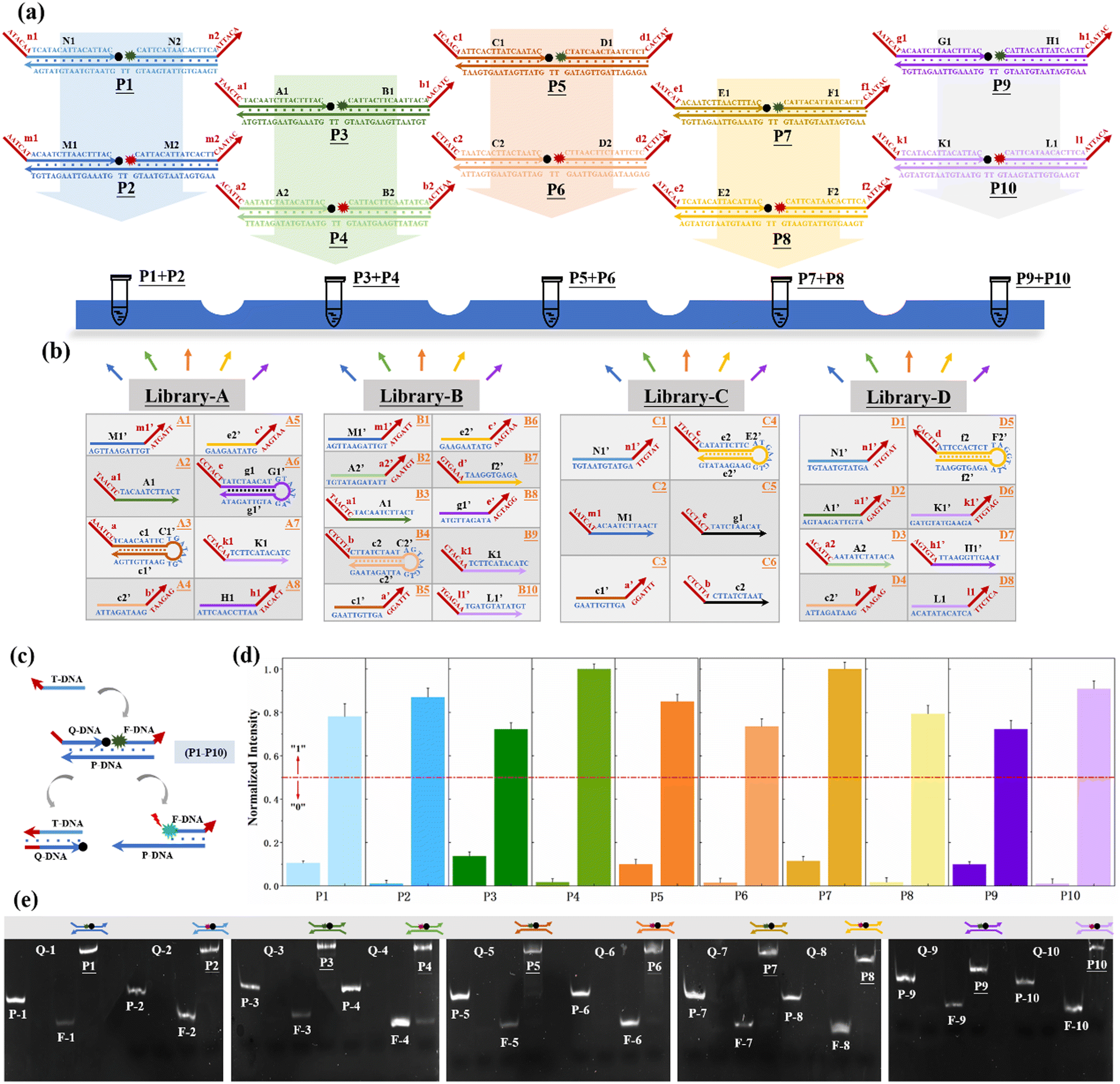
Based on the successful construction of the reaction platform and its input library, in the next step, we need to determine the logical relationship between each subset of the input (or each single-stranded input DNA) and platform monomers. In this work, the square root (or cube root) logic operation of 4-bit-input and 10-bit-output is performed based on three basic logic gates, namely,the “OR” gate, “AND” gate, and “NAND” gate, as shown in Fig. 3(a). The input sequences involved in the operation of the three gates are defined as single-control switch (sc-SW), double-control switch (dc-SW), and blocking switch (bl-SW), respectively, as shown in Fig. 3(b). In the “OR” gate, based on the corresponding truth table, the coding relationship between the input DNA and reaction platform is as follows: any input sequence known as sc-SW can undergo TDSD reaction with the reaction platform, resulting in the recovery of the fluorescence signal (from low fluorescence intensity of “0” to high fluorescence intensity of “1”). In the “AND” gate, the logical relationship between the input and platform is as follows: only when two input DNAs exist at the same time can the fluorescence signal of the reaction platform be stimulated to restore it to the high level of “1”, and the two coexisting inputs involved in “AND” gate operation are called dc-SW. In the “NAND” gate, which is a series of the “AND” gate and “NOT” gate, the logical relationship between its corresponding inputs and the platform is that only when two inputs exist at the same time can the fluorescence signal of the reaction platform be suppressed, otherwise, the fluorescence signal output will be high (“1”). In this case, the two existing inputs involved in the “NAND” gate operation are called bl-SW. Based on this, similar to traditional electronic circuits, the logic circuit diagrams composed of DNA inputs, DNA-based reaction platform and the logical relationship between them are shown in Fig. 3(c) and Fig. S5 (ESI†), which are used to realize the calculation of square roots and cube roots. Different from the traditional circuit, the DNA-based logic circuit in this work uses fluorescence signals as an output indicator.
 | ||
| Fig. 3 (a) Three basic logic gates, namely, the “OR” gate, “AND” gate, and “NAND” gate, and the corresponding truth table are used in this work to realize the operation of square root and cube root logic circuits. (b) The DNA hybridization/TDSD reactions involved in the operation of three logic gates are encoded. (c) Logic circuit diagram for realizing square root calculation. | ||
Next, we systematically describe the successful implementation of square root logic operation based on the response of each subset in the input “library” and the reaction platform, as shown in Fig. 4. Due to a large amount of computation and the similarity of the reaction mechanism, we select the calculation of “ ”, “
”, “ ”, “
”, “ ” and “
 ” as typical examples to illustrate. In this work, to run for the calculation of any object, each of the input sequence is only involved in the following three conditions of reaction, namely, as a sc-SW directly reacting with the reaction platform to light it up, a dc-SW together with other sequence to “light up” the platform, and a bl-SW to ensure that an input sequence can hinder the active site of the sc-SW, which prevents it from “lighting up” the platform. First, in order to operate the calculation of “
 ”, only input-A set is encoded as participating in the operation reaction according to the truth table, that is, its subset-input-A1 performs TDSD reaction with the P-2 nanoswitch in the reaction platform, restoring the quenched HEX fluorescence signal modified on P-2 (i.e., from output binary “0” to “1”). Other nanoswitches in the reaction platform do not participate in the calculation, and the fluorescence signal remains binary “0”. Second, in order to operate the calculation of “
 ”, the input-A set (subsets A1, A3, A4, A6) and input-B set (subsets B1, B2, B4, B5, B8, and B10) are encoded as participating in the operation reaction. In this operation, the recovery of fluorescence signals (P-2, P-4, P-5, P-6, P-9, and P-10) depends on two switch modes, namely, sc-SW and dc-SW. In the sc-SW, any input DNA can undergo TDSD reaction with the corresponding platform and restore the fluorescence intensity of “1”. For example, input-A1 or B1 can react with P-2 and result in an enhanced HEX fluorescence signal. In the dc-SW, only when all the input DNAs are added can the TDSD reaction take place with the corresponding nanoswitch platform and the fluorescence intensity is restored to “1”. For example, only when input-A3 and B5 are added simultaneously, TDSD reaction can occur with P-5, resulting in an enhanced FAM fluorescence signal.
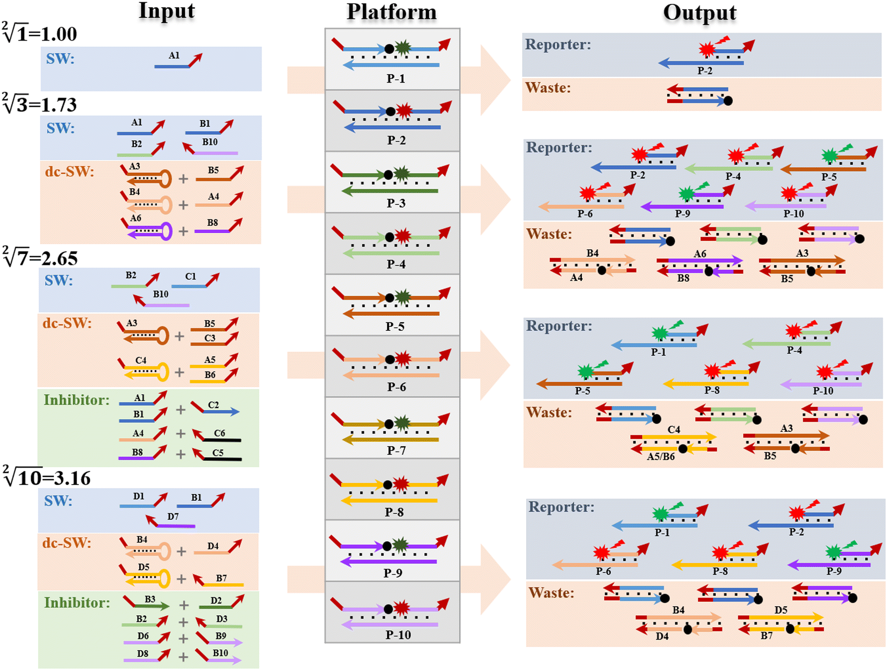 | ||
Fig. 4 Description of the reactions between the inputs and platform to demonstrate the successful operation of 10-bit-output square root logic circuits. The calculations of “ ”, “ ”, “ ”, “ ”, “ ” and “ ” and “ ” were selected as typical examples to illustrate. ” were selected as typical examples to illustrate. | ||
Third, in order to operate the calculation of “ ”, the input-A set (subsets A1, A3, A4, A5, and A6), input-B set (subsets B1, B2, B4, B5, B6, B8, and B10) and input-C set (subsets C1, C3, C4, C5, and C6) are encoded as participating in the operation reaction. In this calculation, the recovery of fluorescence signals (P-1, P-4, P-5, P-8, and P-10) depends on three switching modes, namely, sc-SW, dc-SW and bl-SW, in which the sc-SW and dc-SW modes are committed to enhancing the fluorescence intensity from “0” to “1”, as described above. However, the bl-SW mode in this operation works to prevent the fluorescence signal from becoming stronger (detailed description is shown in Fig. S6, ESI†). For example, the added input-C6 can preferentially hybridize with input-A4, blocking its active site that can open the hairpin structure of B4, which can “light up” the HEX fluorescence of P-6. Finally, in order to operate the calculation of “
 ”, the input-B set (subsets B1, B2, B3, B4, B7, B9, and B10) and input-D set (subsets D1, D2, D3, D4, D5, D6, D7, and D8) are encoded as participating in the operation. In this calculation, the recovery of fluorescence signals (P-1, P-2, P-6, P-8, and P-9) depends on three switching modes, namely, sc-SW, dc-SW and bl-SW. The detailed working mechanism of bl-SW in this operation is shown in Fig. S6 (ESI†). All computed output signals are analysed in sequence by modular segmentation, testing, and analysis. Based on this reaction mechanism, in this work, we successfully implement the square root and cube root logic operation of decimal integers up to 10, which is almost the most complex logical calculation with the largest scale of fluorescence outputs based on DNA computation so far.
As shown in Fig. 5 and Fig. S7 (ESI†), the fluorescence intensity values output by the system was normalized and the threshold was defined to confirm the successful operation of the 10-bit output square root and cube root logic circuit. Thresholding is actually the digital abstraction of the output signal, namely, binarization operation.10 It is the basic principle of digital logic in electronics—by pushing essentially analog signals toward ideal ON or OFF values, which is the binary number of “0” or “1”.27 Similar to the approach applied in electronic circuits, in this work, the output threshold value is defined as “1” when the normalized fluorescence intensities are higher than 0.5. On the contrary, the output threshold value can be defined as “0” when the normalized fluorescence intensities are lower than 0.5. Due to thresholding, the problem of signal interference caused by the presence of multiple input signals can be effectively avoided to ensure the ideal OFF and ON states of output signals, and maintain the digital abstraction.
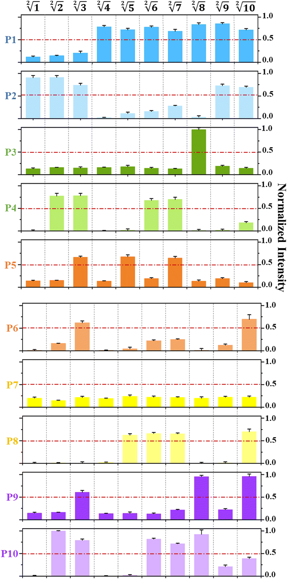 | ||
| Fig. 5 Histogram of normalized fluorescence output intensities of P1 to P10 within the calculation range of any integer up to “1 ≤ x ≤ 10” in the square root operation. The error bars are obtained via three independent experiments and denote standard deviation (S.D.). | ||
4 Conclusions
In summary, in order to construct complex logic circuits to expand the scope of computation, to realize the integration and scalability of circuits, and further promote the completion of larger-scale logic circuits, we have made improvements from three aspects in this work. First, to increase the coding capacity and provide a more flexible and large addressable range for downstream reaction platforms, a DNA sequence “library” is constructed to support a multi-channel signal input. Second, a multi-component, multi-functional and highly stable DNA-nanostructure-based system is constructed as a reaction platform for large-scale complex logic operations. Third, in order to obtain a large-scale distinguishable fluorescence output channel, the 10-bit output binary number is divided into three parts in a modular manner. In addition, the resulting logic output signals are thresholded, by pushing essentially analog signals toward ideal ON or OFF values, which is the basic principle of digital logic in electronics. Based on this, depending on the same reaction system, we successfully realized the calculation of both square roots and cube roots of consecutive integers within the decimal number of “10”, and in each result of operation, two digits after the decimal point are preserved ( ). It is worth noting that the implementation of such a relatively large-scale logical system is based only on predictable DNA hybridization reactions and TDSD, which provides a robust database and unique structural programmability to DNA to open up inspiring horizons for designing novel functional devices and complicated computing circuits. We promise that in the future, based on the design concept of this work and the powerful DNA chain displacement reaction, we will continue to explore in depth to achieve larger and more complex logic computations, achieving qualitative improvements on a computational scale.
Conflicts of interest
The authors declare no competing interests.Acknowledgements
This work was supported by the Strategic Priority Research Program of the Chinese Academy of Sciences (no. XDA22040203) and the National Natural Science Foundation of China (grant 42006061).References
- P. A. de Silva, N. H. Q. Gunaratne and C. P. McCoy, A Molecular Photoionic AND Gate Based on Fluorescent Signaling, Nature, 1993, 364, 42–44 CrossRef.
- J. Elbaz, O. Lioubashevski, F. Wang, F. Remacle and R. D. Levine, DNA Computing Circuits Using Libraries of DNAzyme Subunits, Nat. Nanotechnol., 2010, 5, 417–422 CrossRef CAS PubMed.
- L. Qian, E. Winfree and J. Bruck, Neural Network Computation with DNA Strand Displacement Cascades, Nature, 2011, 475, 368–372 CrossRef CAS PubMed.
- I. Willner, B. Shlyahovsky, M. Zayats and B. Willner, DNAzymes for Sensing, Nanobiotechnology and Logic Gate Applications, Chem. Soc. Rev., 2008, 37, 1153–1165 RSC.
- L. Adleman, Molecular Computation of Solutions to Combinatorial Problems, Science, 1994, 266, 1021–1024 CrossRef CAS PubMed.
- L. Qian and E. Winfree, Scaling Up Digital Circuit Computation with DNA Strand Displacement Cascades, Science, 2011, 332, 1196–1201 CrossRef CAS PubMed.
- Y. J. Chen, B. Groves, R. A. Muscat and G. Seelig, DNA Nanotechnology from the Test Tube to the Cell, Nat. Nanotechnol., 2015, 10, 748–760 CrossRef CAS PubMed.
- B. Q. Ding and N. C. Seeman, Operation of A DNA Robot Arm Inserted into a 2D DNA Crystalline Substrate, Science, 2006, 314, 1583–1585 CrossRef CAS PubMed.
- M. R. Jones, N. C. Seeman and C. A. Mirkin, Programmable Materials and the Nature of the DNA Bond, Science, 2015, 347, 1260901 CrossRef PubMed.
- C. Y. Zhou, H. M. Geng, P. F. Wang and C. L. Guo, Programmable DNA Nanoindicator-Based Platform for Large-Scale Square Root Logic Biocomputing, Small, 2019, 15, 1903489 CrossRef CAS PubMed.
- C. Y. Zhou, H. M. Geng, P. F. Wang and C. L. Guo, Ten-Input Cube Root Logic Computation with Rational Designed DNA Nanoswitches Coupled with DNA Strand Displacement Process, ACS Appl. Mater. Interfaces, 2020, 12, 2601–2606 CrossRef CAS PubMed.
- Q. Tang, W. Lai, P. Wang, X. Xiong, M. Xiao, L. Li, C. Fan and H. Pei, Multi-Mode Reconfigurable DNA-Based Chemical Reaction Circuits for Soft Matter Computing and Control, Angew. Chem., Int. Ed., 2021, 60, 15013–15019 CrossRef CAS PubMed.
- J. Chao, J. Wang, F. Wang, X. Ouyang, E. Kopperger, H. Liu, Q. Li, J. Shi, L. Wang, J. Hu, L. Wang, W. Huang, F. C. Simmel and C. Fan, Solving Mazes with Single-molecule DNA Navigators, Nat. Mater., 2019, 18, 273–279 CrossRef CAS PubMed.
- H. Geng, C. Zhou and C. Guo, DNA-based Digital Comparator Systems Constructed by Multifunctional Nanoswitches, Nanoscale, 2019, 11, 21856–21866 RSC.
- Y. Zhang, W. W. Chen, Y. Y. Fang, X. B. Zhang, Y. Liu and H. X. Ju, Activating a DNA Nanomachine via Computation across Cancer Cell Membranes for Precise Therapy of Solid Tumors, J. Am. Chem. Soc., 2021, 143, 15233–15242 CrossRef CAS PubMed.
- Y. Mi, J. Zhao, H. Chu, Z. Li, M. Yu and L. Li, Upconversion Luminescence-Controlled DNA Computation for Spatiotemporally Resolved, Multiplexed Molecular Imaging, Anal. Chem., 2021, 93, 2500–2509 CrossRef CAS PubMed.
- C. Emanuelson, A. Bardhan and A. Deiters, DNA Computing: NOT Logic Gates See the Light, ACS Synth. Biol., 2021, 10, 1682–1689 CrossRef CAS PubMed.
- J. Y. Dong, M. Wang, Y. H. Zhou, C. Zhou and Q. B. Wang, DNA-Based Adaptive Plasmonic Logic Gates, Angew. Chem., Int. Ed., 2020, 59, 15038–15042 CrossRef CAS PubMed.
- L. L. Li, W. Y. Lv, Y. Wang, Y. F. Li, C. M. Li and C. Z. Huang, DNA Logic Nanodevices for Real-Time Monitoring of ATP in Lysosomes, Anal. Chem., 2021, 93, 15331–15339 CrossRef CAS PubMed.
- Y. Zhang, W. W. Chen, Y. Y. Fang, X. B. Zhang, Y. Liu and H. X. Ju, Activating a DNA Nanomachine via Computation across Cancer Cell Membranes for Precise Therapy of Solid Tumors, J. Am. Chem. Soc., 2021, 143, 15233–15242 CrossRef CAS PubMed.
- H. M. Geng, C. Y. Zhou and C. L. Guo, DNA-based digital comparator systems constructed by multifunctional nanoswitches, Nanoscale, 2019, 11, 21856–21866 RSC.
- C. Zhang, J. Yang, S. Jiang, Y. Liu and H. Yan, DNAzyme-Based Logic Gate-Mediated DNA Self-Assembly, Nano Lett., 2016, 16, 736–741 CrossRef CAS PubMed.
- B. I. Harding, N. M. Pollak, D. Stefanovic and J. Macdonald, Repeated Reuse of Deoxyribozyme-Based Logic Gates, Nano Lett., 2019, 19, 7655–7661 CrossRef CAS PubMed.
- C. Y. Zhou and C. L. Guo, Design of DNA-based Innovative Computing system of Digital Comparison, Acta Biomater., 2018, 80, 58–65 CrossRef CAS PubMed.
- H. M. Geng, C. Y. Zhou and C. L. Guo, Construction of a Simple and Intelligent DNA-based Computing System for Multiplexing Logic Operations, Acta Biomater., 2020, 118, 44–53 CrossRef CAS PubMed.
- M. Rana, E. E. Augspurger, M. S. Hizir, E. Alpa and M. V. Yigit, Molecular Logic Gate Operations Using One-dimensional DNA Nanotechnology, J. Mater. Chem. C, 2018, 6, 452 RSC.
- A. Ogawa and M. Mae, Easy Design of Logic Gates based on Aptazymes and Noncrosslinking Gold Nanoparticle Aggregation, Chem. Commun., 2009, 4666–4668 RSC.
Footnote |
| † Electronic supplementary information (ESI) available. See DOI: https://doi.org/10.1039/d2nh00525e |
| This journal is © The Royal Society of Chemistry 2023 |