DOI:
10.1039/D2NH00518B
(Communication)
Nanoscale Horiz., 2023,
8, 353-360
High temperature phases of borophene: borophene glass and liquid†
Received
4th November 2022
, Accepted 3rd January 2023
First published on 11th January 2023
Abstract
Borophene is a family of two-dimensional (2D) boron materials containing many isomers with different hole concentrations and distributions in a triangular lattice. Although it has been widely studied theoretically and some have been synthesized experimentally, their thermodynamic properties are still unexplored. Based on density functional theory (DFT), we developed an accurate potential for the kinetic Monte Carlo (kMC) simulations of borophene. Through extensive kMC simulations, new phases were discovered, such as the glass state of borophene, liquid borophene and borophene with large holes. A phase diagram of borophene is constructed to guide future experiments on borophene materials at high temperature.
New concepts
Although the properties of various borophene isomers have been extensively studied, their thermodynamic properties are still unexplored. The lack of highly accurate force fields of 2D boron structures prevents studies of their thermodynamic properties using molecular dynamic (MD) simulations. Here we present a kinetic Monte Carlo (KMC) simulation of borophene at high temperatures by using the local descriptors based potential energy surface. In this study, we have revealed the temperature dependent thermodynamic properties of 2D borophene materials: (1) a few high temperature phases of borophene, such as the borophene glass and liquid 2D borophene with large holes, have been revealed for the first time. It is interesting that large holes in a liquid borophene are stable even at very high temperature, which contradicts our intuition that a liquid bubble will break if it has a hole; (2) the line defects in borophene polycrystals, which have been reported in experimental studies, were also observed in our KMC simulations; (3) we have developed a phase diagram of borophene and it will guide future experimental studies on various phases of borophene.
|
1 Introduction
Since the experimental realization of graphene1 and the discovery of its charge carrier properties,2,3 numerous two-dimensional (2D) materials have been synthesized and explored. Their excellent characteristics make them promising for various industrial applications.4–13 Borophene is a large family of 2D boron materials with different structures with distinctive physical and chemical properties.14–25 The one-electron deficiency of boron compared to carbon leads to the three-center two-electron (3c-2e) bonding configuration, as a unique property, of the borophene isomers. A flat triangular boron sheet has surplus electrons while a hexagonal one is electron deficient,26 thus flat 2D borophene can be stabilized by mixing triangular and hexagonal lattices playing the roles of the electron donor and acceptor in the borophene, respectively. In other words, a highly stable borophene can be considered as a triangular lattice with a certain number of hexagonal holes; the hole concentration, η, being a key factor, which determines the stability of a borophene structure.27,28
In 2015, Yakobson and co-workers proposed that, due to the charge doping effect, various borophene phases with different η can be formed on metal surfaces with different work functions, namely on Au, Ag, Cu and Ni.29 Based on their predictions, borophene was synthesized for the first time on a Ag(111) substrate.30 Several other phases of borophene, such as 2-Pmmn, β12, χ3, and honeycomb ones, were successfully synthesized later.31–36 Although the stability and electronic properties of various borophene isomers have been extensively studied,26–28,37–41 their thermodynamic properties are still unexplored, since the lack of highly accurate force fields of 2D boron structures (dependent on the concentration and the arrangement of holes) prevents studies of their thermodynamic properties using molecular dynamic (MD) simulations. And using ab initio MD simulations is prevented by the high computational cost and time required.
In this work, we used kinetic Monte Carlo (kMC) simulations to explore the temperature dependent structures and properties of borophene with different hole concentrations. We developed a highly accurate potential energy surface (PES) fitted to first principle calculations of non-equivalent 3169 flat 2D borophene isomers without any substrate to explore high temperature phases of borophene. The freestanding borophene and borophene synthesized on various substrates share very similar properties: such as (1) both are based on the triangular lattice, (2) the most stable structure of both has a certain number of hexagonal holes. So, due to the weak interaction between borophene and the substrate, stable phases at each hole concentration can be similar to those synthesized on substrates, such as on Ag(111).42 Our kMC simulations reveal new phases of borophene at low and high temperatures: (1) the borophene glass state at low hole concentrations, (2) liquid borophene at high temperature, and (3) borophene with solid large holes at high hole concentrations. Finally, a phase diagram of borophene is constructed.
2 Methods
2.1 DFT calculations for linear fitting
To fit the formation energy Ef for kMC simulations, we generated 3169 free-standing 2D flat borophene structures without any constraints on the hole size. Their unit cell sizes range from 3 × 3 to 8 × 8, with the hexagonal unit cell taken from our previous results.41 We performed density functional theory (DFT) calculations with the Perdew–Burke–Ernzerhof (PBE) exchange–correlation functional and the generalized gradient approximation (GGA) using the Vienna ab initio Simulation Package (VASP, 5.4.4 version).43–45 The plane-wave cutoff was set to 400 eV with the convergence criterion for the SCF iterations set to 10−5 eV. Vacuum slabs of more than 15 Å were used and the Brillouin zone was sampled with a k-points density of 0.03 Å−1. We performed optimization of the lattice cell and atomic positions until the convergences of the forces on all atoms were less than 0.01 eV Å−1.
2.2 Linear regression for the potential energy surface and transition energy
We constructed a local descriptor for the potential (formation) energy. We used the DFT results for 5 × 5 borophene structures as a fitting set and the other size structures as a test set. The datasets were generated by embedding the boron atoms onto each closest lattice site after the geometry optimization. Let X: j → i ∈ Λ be a local descriptor mapping the boron–atom site j ∈ {1, …, N} (i.e., the atomic index in borophene) onto i as a component of the decomposed coordinate numbers (DCNs) set Λ = {0, 1, 2, …, 611, 612} including 25 DCN types (more details are given in Fig. S1, ESI†). We also considered an indicator function ϕi: Λ → ![[Doublestruck Z]](https://www.rsc.org/images/entities/char_e17d.gif) 2 mapping the DCN types onto {0, 1}, which gives 1 if i has i-type DCN or 0 otherwise. Next, we defined the formation energy as
2 mapping the DCN types onto {0, 1}, which gives 1 if i has i-type DCN or 0 otherwise. Next, we defined the formation energy as 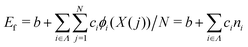 , where b and ci are coefficients with a unit as [b] = [ci] = eV per atom, ni = Ni/N is the proportion of i-type configuration, Ni is the number of i-type boron atoms, and N is the number of all boron atoms.
To parametrize a constant term b and the corresponding coefficients ci of the formation energy, we defined the formation energy Ef = Evac − Ebulk obtained after the optimization, where Evac and Ebulk are the borophene energies with/without holes, respectively. The coefficients in the formation energy were fitted by the ordinary least squares (OLS) method.46
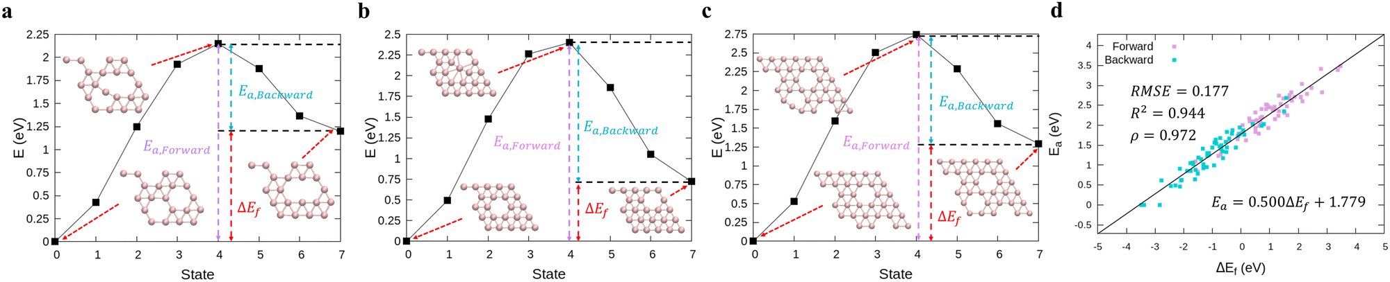
To calculate the transition energy Ea for the exchange of positions between a boron atom and the nearest hole (≤6 cases for each transition), we performed DFT calculations using the climbing image nudged elastic band (cNEB) method.47,48 We chose 16 structures on the baseline of Fig. 1a including the stable borophene structures at certain hole concentrations with 5 × 5 and 6 × 6-unit cells and their possible transitions shown in Fig. S3 (ESI†). We fitted the coefficients a and b for the transition energy Ea as a function of the formation energy difference ΔE between two states (i.e., Ea = aΔE + b) by the OLS method.
 |
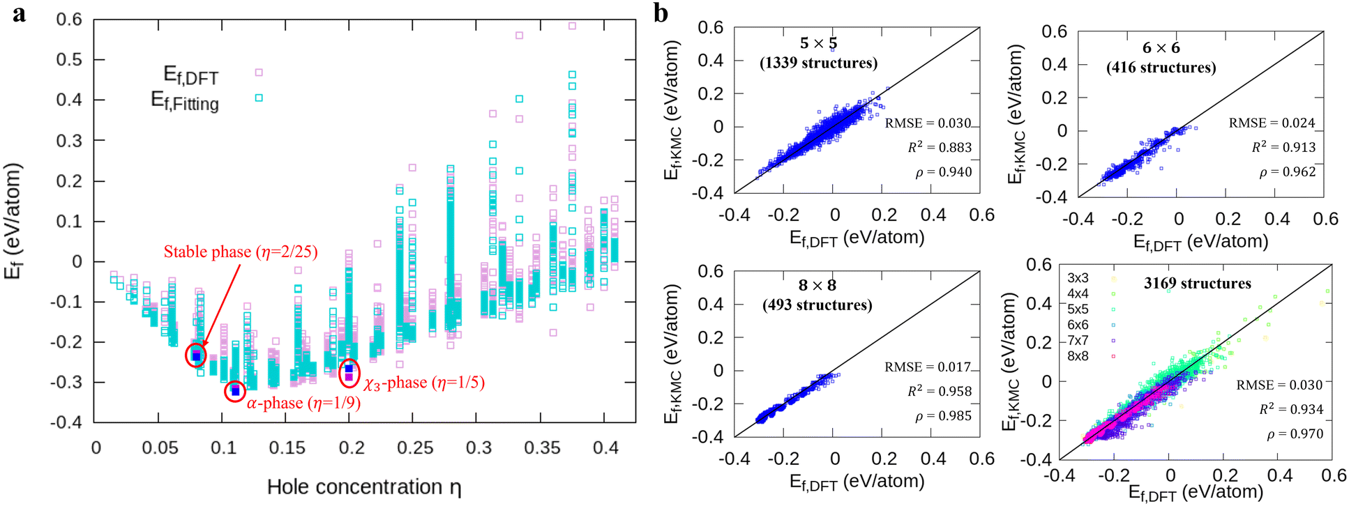
| | Fig. 1 Comparison of the formation energies Ef obtained by DFT and our model. (a) The energy landscapes of the DFT results and our model versus the hole concentration η, (b) the correlation between DFT and our model results with different unit cell sizes (5 × 5, 6 × 6, 8 × 8, and all structures). We denote the DFT and fitting results for 3 stable phases as magenta and blue squares in (a), respectively. | |
2.3 Evaluation of the fitted model compared with the DFT results
To evaluate the accuracy of our model,46 we obtained the root mean squared error (RMSE) value estimated by the DFT results given by| |  | (1) |
where Nstr is the number of structures, and Efit and EDFT are the formation energy from our model and the DFT results, respectively. To check how well our model can predict the potential energy compared with the DFT calculations, we calculated the coefficient of determination R2 as| | 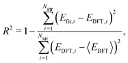 | (2) |
where 〈·〉 denotes the mean value. In addition, for quantitative estimation of the linear relationship between our model and the DFT results, we obtained the Pearson correlation coefficient ρ given by| | 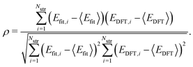 | (3) |
2.4 Pattern description of borophene structures
To describe the borophene patterns, we defined the boron atom density m(i) as the local distribution of boron atoms around a boron atom located at the ith site. The density is defined as 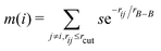 normalized by the same calculation with the bulk borophene (without holes), where s is an indicator function that is equal to 1 when two boron atoms are located at each i and j site, and 0 otherwise, rij is the distance between two sites, rB–B is the bond length of the bulk borophene and rcut is the cut-off radius. In this study, we set rcut = 5rB–B. We denoted different colors depending on the magnitude of the boron density as following the order: blue, cyan, magenta, and white (hole). All atomic structures for the colored maps in Fig. 3 and 4 are given in Fig. S4 (ESI†).
2.5 Kinetic Monte Carlo simulations
We built up an in-house code with the potential energy surface for the kMC simulations in Fortran. To distinguish the equivalent DCNs induced by translation, rotations, and reflections, we apply the Gödels numbering (or encoding) to the code for the energy calculations (more details are given in Fig. S5 and Algorithm in the ESI†) with the periodic boundary conditions (PBC).
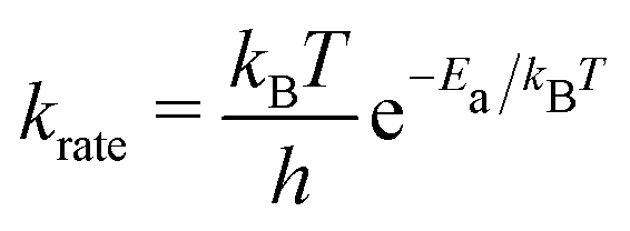
We performed the simulations with the different hole concentrations, η = 0.1, 0.11, 0.12, 0.14, and 0.2 in 100 × 100 lattice sites with the hexagonal unit cells and monotonously drop the temperature of the systems. The temperature of the borophene systems starts from 1400 K to 500 K with two temperature drop rates: either 1 K/(100 × N) trials of the boron-hole exchange, or 1 K/1 second if the kMC step is over 100 × N trials at each temperature, because the computational time is too long if using only the rate 1 K/1 second at high temperature and, otherwise, the time evolution is not realistic at low temperature. All initial configurations are randomly generated, and 105 steps are performed for structure relaxation at 1400 K. The boron-hole exchange rate krate for the kMC simulations was calculated by 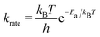 , where kB and h are the Boltzmann/Plank constants, respectively, T is temperature, and Ea is the transition energy measured by eqn (5). The time evolution during the hole-boron exchange is calculated by
  , where r is the uniform random number in U(0,1], and Ntrans is the number of possible transitions.
2.6 Large hole stability using AIMD simulations
To further verify the stability of the double layers of boron atoms around large holes for high hole concentration, we performed ab initio molecular dynamics (AIMD) simulations with cooling and the PBC. Initial structures, with 10 × 10-unit cell, are generated with η = 0.18 in a hexagonal system box (a = b = 17.10 Å and c = 29.18 Å with α = β = 90°, γ = 120°). The plane-wave cutoff was set to 250 eV with the local density approximation.49 We simulated the cooling process from 2400 K to 1800 K using a Nose–Hoover thermostat.50–52 We constrained the movement of the boron atoms in the normal direction of borophene (c-direction) to keep the borophene flat.
3 Results and discussion
3.1 Fitting parameters of the potential energy surface
First, we modeled the formation energy Ef of a borophene isomer using the DCNs as a local descriptor and the DFT calculated energies.41 The formation energy Ef is formulated as follows:| | 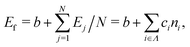 | (4) |
where b is a constant that represents the energy of a boron atom in a triangular lattice, Ej is the corresponding energy of the jth boron, N is the total number of the boron atoms in the system, Ni is the number of boron atoms in the configuration i, ni = Ni/N is the proportion of i-type configuration, and ci is the corresponding formation energy of the local configuration i. Unlike in our previous study,41 we considered the boron-hole arrangements of not only first neighbors but also the second neighbors of the central boron atom in order to distinguish configurations with identical first neighbors for i = 5 and 6 in isomers. The details are given in Fig. S1 and Table S1 of the ESI.†
Fig. 1a shows formation energies of borophene isomers with various hole concentrations, η, calculated using DFT and our model. Our model agrees with previous studies,41,42 where the formation energy shows very similar hole concentration dependence with α-borophene (η = 1/9) being the most stable isomer. Fig. 1b shows the DFT calculated formation energies versus the fitted ones for different unit-cell sizes: 5 × 5, 6 × 6, and 8 × 8 as well as for all the samples. The root mean squared error (RMSE), the coefficient of determination R2, and the Pearson correlation coefficient ρ of each fitting are also shown. The 5 × 5 borophene isomers were used for fitting, with an RMSE of 0.030 eV per atom, R2 of 0.883, and ρ of 0.940. The 6 × 6 and 8 × 8 borophene isomers were used for testing with an RMSE, R2 and ρ of 0.024, 0.017 eV per atom, 0.913, 0.958, and 0.962, 0.985, respectively. Other borophene isomers (3 × 3, 4 × 4 and 7 × 7 sizes) produce a similar quality of fitting, as shown in Fig. S2 (ESI†). For the set of all structures, we obtained an RMSE of 0.030 eV per atom, R2 of 0.934, and ρ of 0.970. The error of 0.030 eV per atom lies within the error range of standard DFT methods, and thus we conclude that the fitted formation energies represent the DFT calculations very well.41,42
In order to perform kMC simulations, which can be used to describe the kinetics of a system evolution properly, we also formulated the transition energy Ea for hole diffusion in various borophenes (see Fig. S3, ESI†). Fig. 2a–c show three transition processes of stable phases with the energy differences ΔEf and the corresponding transition energies Ea. Including both forward and backward reactions, the energy barrier for the diffusion can be fitted by a linear relationship (see Fig. 2d):
| | | Ea = 0.500ΔEf + 1.779, | (5) |
with an RMSE,
R2, and
ρ of 0.177 eV, 0.944, and 0.972, respectively.
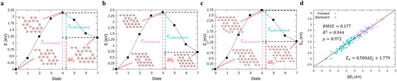 |
| | Fig. 2 (a)–(c) Calculations of relative energies for the hole diffusion in a few typical borophene structures denoted at Fig. 1(a) using the cNEB method. These structures are for (a) χ3-phase (η = 1/5), (b) one of the stable borophene structures in the dataset (η = 2/25), and (c) α-phase (η = 1/9). (d) Linear regression between the transition energies and the energy differences. | |
3.2 Kinetic Monte Carlo simulations
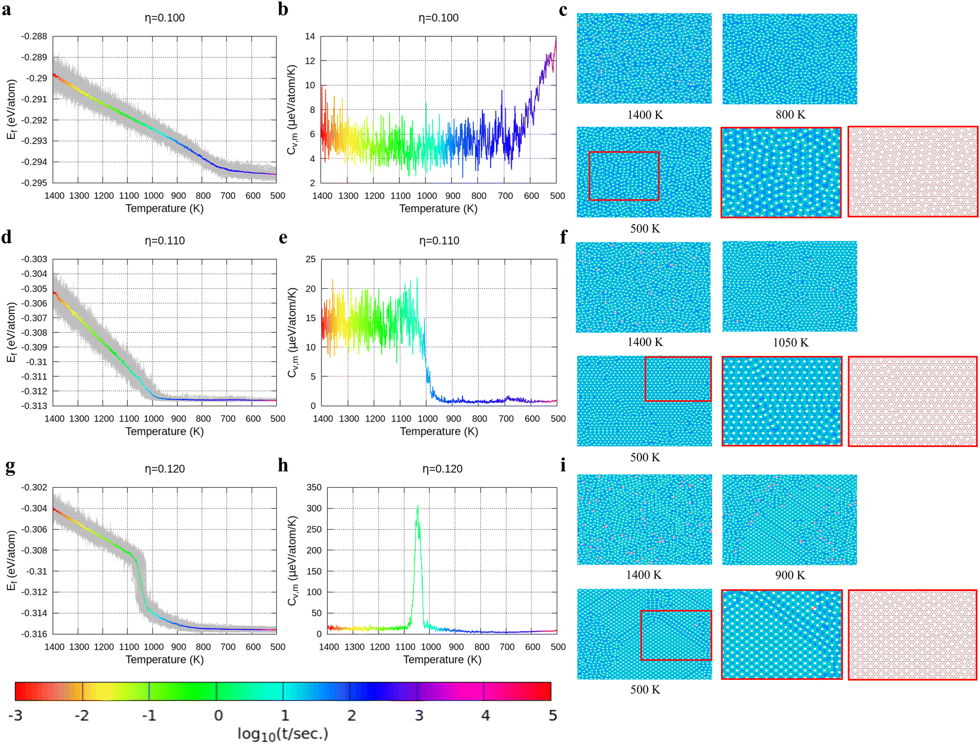
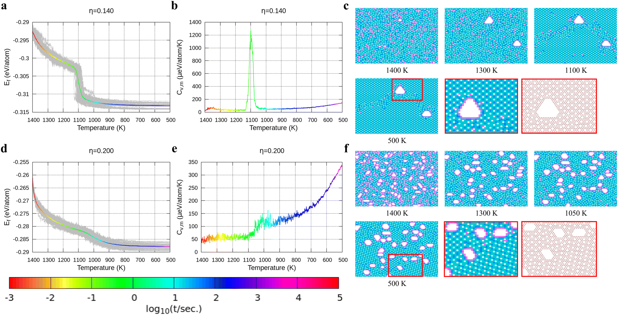
With the above energy surface and barriers of the diffusion, we performed kMC simulations to explore the cooling process of borophene with different hole concentrations, η = 0.1, 0.11, 0.12, 0.14, and 0.2, starting from random structures. The initial temperature was set to 1400 K, which is much higher than the melting point of 2D borophene (about 1000 K as shown in Fig. 3 and 4). The final temperature was set to 500 K, which is significantly lower than the melting point. Fig. 3 and 4 show the formation energy and heat capacity of various borophene structures as a function of temperature and different hole concentrations (η = 0.1–0.12 in Fig. 3, and η = 0.14 and 0.2 in Fig. 4). The heat capacity with constant volume is obtained by Cv,m = (∂Ef/∂T)V = N(〈Ef2〉 − 〈Ef〉2)/(kBT2). Typical borophene structures at different temperatures are also shown.
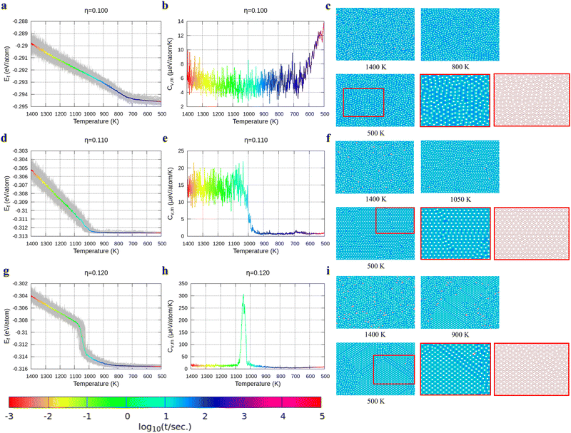 |
| | Fig. 3 Formation energy and heat capacity during cooling from 1400 K to 500 K as well as density maps of typical borophene configurations for different temperatures, and at different hole concentrations: (a)–(c) η = 0.1, (d)–(f) η = 0.11, and (g)–(i) η = 0.12. Colors in the borophene structures at different temperatures denote the boron atom density with the magnitude order: blue > cyan > magenta > white (hole). | |
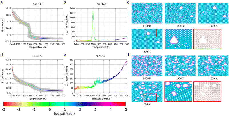 |
| | Fig. 4 Formation energy and heat capacity during cooling from 1400 K to 500 K as well as density maps of typical borophene configurations for different temperatures, and at different hole concentrations: (a)–(c) η = 0.14 and (d)–(f) η = 0.2. | |
For borophene with η = 0.1 in Fig. 3a, the formation energy monotonously decreases during the cooling process until around 720 K where the slope changes rapidly from 5.9 to 1.5 μeV per K per atom, implying freezing of the borophene structure. Fig. 3b shows that the heat capacity quickly rises at the same temperature. As seen in Fig. 3c, the borophene structure with η = 0.1 is amorphous during cooling from 1400 K to 500 K. The increase in heat capacity after the freezing point implies a rapid decrease of the configuration entropy of the borophene structure below 720 K. From this simulation, we conclude that a solid phase of amorphous borophene can be obtained by fast cooling at low hole concentration.
Fig. 3d shows the cooling of borophene with η = 0.11 where around 1000 K the slopes of both the energy and the heat capacity quickly change to zero (Fig. 3d and e). This implies a phase transition from amorphous to crystalline, which has the lowest formation energy and zero configuration entropy. Fig. 3f proves that α-borophene nuclei start to appear from amorphous borophene at about 1050 K. The growth of α-borophene grains and their coalescence finally leads to a complete α-borophene phase with occasional defects. Fig. 3g shows the cooling of borophene with η = 0.12. From 1400 K to about 1050 K, the energy decreases linearly and then drops rapidly. The energy becomes constant at approximately 800 K. In Fig. 3h, a large peak appears in the heat capacity at 1050 K, and the heat capacity converges to about zero after that peak. Both the sudden drop in energy and the peak in the heat capacity imply a first order phase transition of the borophene. As can be seen in Fig. 3i, borophene with η = 0.12 is in a liquid state at temperatures above 1100 K. At about 1100 K, α1-borophene phase with η = 1/8 starts to appear and aggregate. As the α1-borophene has a slightly higher hole concentration than η = 0.12, the whole borophene structure cannot be fully transformed into α1-borophene, so line defects with a lower hole concentration, such as η = 1/9, are observed between the α1-borophene phases. Various line defects with different hole concentrations have been observed on a silver substrate but their formation mechanism has never been revealed before.53
In Fig. 4, we present the cooling of borophene with large hole concentrations. For all of them, the energy and the heat capacity variations are very similar to those of borophene with η = 0.12, implying a first order phase transition from liquid to crystalline borophene at approximately 1100 K (the peak of the heat capacity in Fig. 4b and e). An interesting feature of the final structures is the appearance of large holes (Fig. 4c and f). Each large hole is surrounded by a very stable double-boron chain which maintains its shape at high temperature (T = 1400 K) even though the surrounding borophene is in a liquid phase. In addition, the large holes make borophene stable shown as the rapid energy drop between 1300 and 1400 K (Fig. 4a and d). Simulations of structures with η = 0.14 and η = 0.20 show that, with the increase of the hole concentration, the concentration of the large holes increases but their average size does not change significantly.
3.3 Stability of large holes with a double boron chain
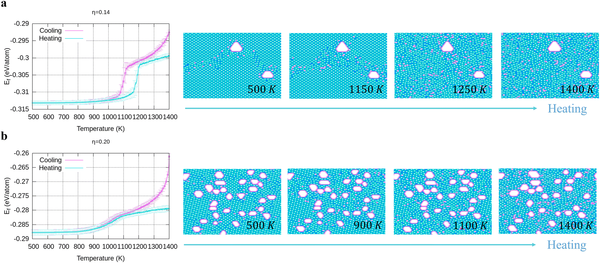
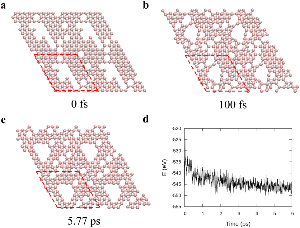
To verify the stability of the large hole formation, we performed additional kMC simulations to heat the final configurations of the cooling processes for η = 0.14 and 0.20; the results are shown in Fig. 5a and b, respectively. The simulations clearly show that the double-boron chains protect the holes and are highly stable as their shapes do not change even when all the surrounding borophene is liquid at 1400 K. So, we shall name this phase as “solid holes” in a liquid borophene. Also, we performed AIMD simulation to explore the cooling process from 2400 K to 1800 K with randomly created 18 single holes near the central area of a 10 × 10-unit cell (Fig. 6a). After 100 fs, a large hole quickly forms in the central area of the unit cell by aggregation of single holes (Fig. 6b). At about 6 ps, a stable large hole with a nearly complete double boron chain is formed (Fig. 6c). The potential energy in Fig. 6d also shows that the large hole makes the borophene stable.
 |
| | Fig. 5 Energy and configuration changes during heating for (a) η = 0.14, and (b) η = 0.2. | |
 |
| | Fig. 6
Ab initio molecular dynamics for a 10 × 10 borophene supercell during cooling from 2400 K to 1800 K with 0.1 K fs−1 cooling rate. (a)–(c) Borophene configurations at specific times: (a) initial, (b) 100 fs, and (c) 5.77 ps and (d) the potential energy during the cooling. Here the red dashed lines denote the unit cell used in the simulations. | |
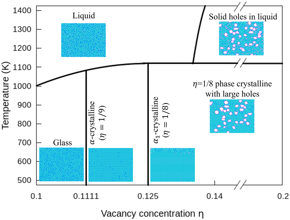
3.4 Phase diagram of freestanding flat 2D borophene
In Fig. 7, we plot a phase diagram of flat 2D borophene based on our kMC simulations. For η < 1/9, borophene is liquid at high temperatures, and it turns into a solid glass state by cooling below 700 K. The glass state can be assessed by comparing the diffusion coefficients as a function of temperature with η = 0.1 and 0.14 in Fig. S6 (ESI†). For η = 1/9 or 1/8, liquid borophene at high temperatures will be crystallized to either α-borophene phase (η = 1/9) or α1-borophene phase (η =1/8) at temperatures lower than the melting point of about 1100 K. At high hole concentrations, large holes protected by double boron chains are first formed in liquid borophene and then embedded in the crystallized η = 1/8 borophene phase at temperatures lower than 1100 K.
 |
| | Fig. 7 Phase diagram of borophene for η = 0.1–0.2 and T = 500–1400 K. | |
4 Conclusions
Using a highly accurate energy surface of 2D boron systems obtained by fitting our model to DFT calculated energies, we reveal unique thermodynamic properties and produce a phase diagram of borophene by kMC simulations. Borophene with a low hole concentration (η = 0.1) tends to be in a glass state at the temperature of T < 720 K because of the lack of highly stable single crystalline structures. Borophene with the medium hole concentration (1/9 < η < 1/8) tends to crystallize into either α-phase or α1-phase. Borophene with a large-hole concentration forms structures of liquid borophene with large holes at high temperatures and 1/8-phase borophene crystals with large holes at lower temperatures. These large holes are surrounded by double boron chains that are highly stable even in liquid borophene. Our study reveals that the glass phase predicts the melting point of 2D borophene to be about 1100 K. In addition, our result shows the high stability of large holes in borophene, and we produce a thermodynamic phase diagram of borophene for the first time. We expect our work to guide further experimental and theoretical studies on the borophene thermodynamic properties.
Author contributions
Y. P. and F. D. conceived and designed this work; Y. W. obtained the dataset for the fitting; Y. P., Y. W., V. G., and F. D. parametrized the potential energy; Y. P. and D. H. discussed AIMD simulations, and Y. P. and X. K. discussed the kMC simulations; Y. P. built up in-house code for the kMC simulations; Y. P. and F. D. wrote manuscript; all authors commented and discussed the manuscript.
Conflicts of interest
There are no conflicts to declare.
Acknowledgements
The authors acknowledge support from the Institute for Basic Science (IBS-R019-D1), South Korea. The authors also acknowledge the use of the IBS-CMCM high-performance computing system “cimulator”.
References
- K. S. Novoselov, A. K. Geim, S. V. Morozov, D. Jiang, Y. Zhang, S. V. Dubonos, I. V. Grigorieva and A. A. Firsov, Science, 2004, 306, 666 CrossRef CAS PubMed.
- K. S. Novoselov, A. K. Geim, S. V. Morozov, D. Jiang, M. I. Katsnelson, I. V. Grigorieva, S. V. Dubonos and A. A. Firsov, Nature, 2005, 438, 197 CrossRef CAS PubMed.
- Y. Zhang, Y.-W. Tan, H. L. Stormer and P. Kim, Nature, 2005, 438, 201 CrossRef CAS PubMed.
- K. Zhang, Y. Feng, F. Wang, Z. Yang and J. Wang, J. Mater. Chem. C, 2017, 5, 11992 RSC.
- H. Schmidt, F. Giustiniano and G. Eda, Chem. Soc. Rev., 2015, 44, 7715 RSC.
- X. Duan, C. Wang, A. Pan, R. Yu and X. Duan, Chem. Soc. Rev., 2015, 44, 8859 RSC.
- B. Radisavljevic, A. Radenovic, J. Brivio, V. Giacometti and A. Kis, Nat. Nanotechnol., 2011, 6, 147 CrossRef CAS PubMed.
- C. R. Dean, A. F. Young, I. Meric, C. Lee, L. Wang, S. Sorgenfrei, K. Watanabe, T. Taniguchi, P. Kim, K. L. Shepard and J. Hone, Nat. Nanotechnol., 2010, 5, 722 CrossRef CAS PubMed.
- Z. Sun, T. Liao, Y. Dou, S. M. Hwang, M.-S. Park, L. Jiang, J. H. Kim and S. X. Dou, Nat. Commun., 2014, 5, 3813 CrossRef CAS PubMed.
- Q. H. Wang, K. Kalantar-Zadeh, A. Kis, J. N. Coleman and M. S. Strano, Nat. Nanotechnol., 2012, 7, 699 CrossRef CAS PubMed.
- M. Osada and T. Sasaki, Adv. Mater., 2012, 24, 210 CrossRef CAS PubMed.
- K. Watanabe, T. Taniguchi and H. Kanda, Nat. Mater., 2004, 3, 404 CrossRef CAS PubMed.
- K. Yoichi, W. Kenji, T. Osamu and T. Takashi, Science, 2007, 317, 932 CrossRef PubMed.
- T. Tsafack and B. I. Yakobson, Phys. Rev. B, 2016, 93, 165434 CrossRef.
- H. Li, L. Jing, W. Liu, J. Lin, R. Y. Tay, S. H. Tsang and E. H. T. Teo, ACS Nano, 2018, 12, 1262 CrossRef CAS PubMed.
- S. Gupta, A. Kutana and B. I. Yakobson, J. Phys. Chem. Lett., 2018, 9, 2757 CrossRef CAS PubMed.
- Z. Zhang, Y. Yang, E. S. Penev and B. I. Yakobson, Adv. Funct. Mater., 2017, 27, 1605059 CrossRef.
- Z. Zhang, E. S. Penev and B. I. Yakobson, Chem. Soc. Rev., 2017, 46, 6746 RSC.
- S.-G. Xu, X.-T. Li, Y.-J. Zhao, J.-H. Liao, W.-P. Xu, X.-B. Yang and H. Xu, J. Am. Chem. Soc., 2017, 139, 17233 CrossRef CAS PubMed.
- B. Peng, H. Zhang, H. Shao, Y. Xu, R. Zhang and H. Zhu, J. Mater. Chem. C, 2016, 4, 3592 RSC.
- E. S. Penev, A. Kutana and B. I. Yakobson, Nano Lett., 2016, 16, 2522 CrossRef CAS PubMed.
- M. Q. Le, B. Mortazavi and T. Rabczuk, Nanotechnology, 2016, 27, 445709 CrossRef PubMed.
- H. R. Jiang, Z. Lu, M. C. Wu, F. Ciucci and T. S. Zhao, Nano Energy, 2016, 23, 97 CrossRef CAS.
- L. Li, H. Zhang and X. Cheng, Comput. Mater. Sci., 2017, 137, 119 CrossRef CAS.
- L. Shi, C. Ling, Y. Ouyang and J. Wang, Nanoscale, 2017, 9, 533 RSC.
- H. Tang and S. Ismail-Beigi, Phys. Rev. Lett., 2007, 99, 115501 CrossRef PubMed.
- X. Wu, J. Dai, Y. Zhao, Z. Zhuo, J. Yang and X. C. Zeng, ACS Nano, 2012, 6, 7443 CrossRef CAS PubMed.
- E. S. Penev, S. Bhowmick, A. Sadrzadeh and B. I. Yakobson, Nano Lett., 2012, 12, 2441 CrossRef CAS PubMed.
- Z. Zhang, Y. Yang, G. Gao and B. I. Yakobson, Angew. Chem., Int. Ed., 2015, 54, 13022 CrossRef CAS PubMed.
- A. J. Mannix, X.-F. Zhou, B. Kiraly, J. D. Wood, D. Alducin, B. D. Myers, X. Liu, B. L. Fisher, U. Santiago, J. R. Guest, M. J. Yacaman, A. Ponce, A. R. Oganov, M. C. Hersam and N. P. Guisinger, Science, 2015, 350, 1513 CrossRef CAS PubMed.
- G. Tai, T. Hu, Y. Zhou, X. Wang, J. Kong, T. Zeng, Y. You and Q. Wang, Angew. Chem., Int. Ed., 2015, 54, 15473 CrossRef CAS PubMed.
- B. Feng, J. Zhang, Q. Zhong, W. Li, S. Li, H. Li, P. Cheng, S. Meng, L. Chen and K. Wu, Nat. Chem., 2016, 8, 563 CrossRef CAS PubMed.
- Q. Zhong, J. Zhang, P. Cheng, B. Feng, W. Li, S. Sheng, H. Li, S. Meng, L. Chen and K. Wu, J. Phys.: Condens. Matter, 2017, 29, 095002 CrossRef PubMed.
- W. Li, L. Kong, C. Chen, J. Gou, S. Sheng, W. Zhang, H. Li, L. Chen, P. Cheng and K. Wu, Sci. Bull., 2018, 63, 282 CrossRef CAS PubMed.
- B. Kiraly, X. Liu, L. Wang, Z. Zhang, A. J. Mannix, B. L. Fisher, B. I. Yakobson, M. C. Hersam and N. P. Guisinger, ACS Nano, 2019, 13, 3816 CrossRef CAS PubMed.
- R. Wu, I. K. Drozdov, S. Eltinge, P. Zahl, S. Ismail-Beigi, I. Božović and A. Gozar, Nat. Nanotechnol., 2019, 14, 44 CrossRef CAS PubMed.
- N. Karmodak and E. D. Jemmis, Angew. Chem., Int. Ed., 2017, 56, 10093 CrossRef CAS PubMed.
- X. Yu, L. Li, X.-W. Xu and C.-C. Tang, J. Phys. Chem. C, 2012, 116, 20075 CrossRef CAS.
- B. Mortazavi, O. Rahaman, A. Dianat and T. Rabczuk, Phys. Chem. Chem. Phys., 2016, 18, 27405 RSC.
- T. R. Galeev, Q. Chen, J.-C. Guo, H. Bai, C.-Q. Miao, H.-G. Lu, A. P. Sergeeva, S.-D. Li and A. I. Boldyrev, Phys. Chem. Chem. Phys., 2011, 13, 11575 RSC.
- Y. Wang, Y. Park, L. Qiu, I. Mitchell and F. Ding, J. Phys. Chem. Lett., 2020, 11, 6235 CrossRef CAS PubMed.
- Y. Liu, E. S. Penev and B. I. Yakobson, Angew. Chem., Int. Ed., 2013, 52, 3156 CrossRef CAS PubMed.
- J. P. Perdew, K. Burke and M. Ernzerhof, Phys. Rev. Lett., 1996, 77, 3865 CrossRef CAS PubMed.
- G. Kresse and J. Furthmüller, Phys. Rev. B: Condens. Matter Mater. Phys., 1996, 54, 11169 CrossRef CAS PubMed.
- G. Kresse and J. Furthmüller, Comput. Mater. Sci., 1996, 6, 15 CrossRef CAS.
-
J. M. Wooldridge, Introductory Econometrics: A Modern Approach, South-Western Cengage Learning, Mason, Ohio, 7th edn, 2019 Search PubMed.
- G. Henkelman, B. P. Uberuaga and H. A. Jónsson, J. Chem. Phys., 2000, 113, 9901 CrossRef CAS.
- G. Henkelman and H. Jónsson, J. Chem. Phys., 2000, 113, 9978 CrossRef CAS.
- W. Kohn and L. J. Sham, Phys. Rev., 1965, 140, A1133 CrossRef.
- S. Nosé, J. Chem. Phys., 1984, 81, 511 CrossRef.
- S. Nosé, Prog. Theor. Phys. Supp., 1991, 103, 1 CrossRef.
- W. G. Hoover, Phys. Rev. A: At., Mol., Opt. Phys., 1985, 31, 1695 CrossRef PubMed.
- X. Liu, Z. Zhang, L. Wang, B. I. Yakobson and M. C. Hersam, Nat. Mater., 2018, 17, 783 CrossRef CAS PubMed.
|
| This journal is © The Royal Society of Chemistry 2023 |
Click here to see how this site uses Cookies. View our privacy policy here. 
 a,
Yong
Wang
ab,
Vladislav
Gladkikh
a,
Yong
Wang
ab,
Vladislav
Gladkikh
 , where b and ci are coefficients with a unit as [b] = [ci] = eV per atom, ni = Ni/N is the proportion of i-type configuration, Ni is the number of i-type boron atoms, and N is the number of all boron atoms.

 normalized by the same calculation with the bulk borophene (without holes), where s is an indicator function that is equal to 1 when two boron atoms are located at each i and j site, and 0 otherwise, rij is the distance between two sites, rB–B is the bond length of the bulk borophene and rcut is the cut-off radius. In this study, we set rcut = 5rB–B. We denoted different colors depending on the magnitude of the boron density as following the order: blue, cyan, magenta, and white (hole). All atomic structures for the colored maps in Fig. 3 and 4 are given in Fig. S4 (ESI†).
 , where kB and h are the Boltzmann/Plank constants, respectively, T is temperature, and Ea is the transition energy measured by eqn (5). The time evolution during the hole-boron exchange is calculated by
 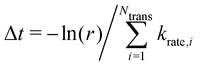 , where r is the uniform random number in U(0,1], and Ntrans is the number of possible transitions.