
In situ characterisation for nanoscale structure–performance studies in electrocatalysis
Tianlai
Xia
ab,
Yu
Yang
a,
Qiang
Song
a,
Mingchuan
Luo
 c,
Mianqi
Xue
b,
Kostya (Ken)
Ostrikov
*d,
Yong
Zhao
*ae and
Fengwang
Li
*a
c,
Mianqi
Xue
b,
Kostya (Ken)
Ostrikov
*d,
Yong
Zhao
*ae and
Fengwang
Li
*a
aSchool of Chemical and Biomolecular Engineering and The University of Sydney Nano Institute, The University of Sydney, NSW 2006, Australia. E-mail: fengwang.li@sydney.edu.au; yong.zhao@sydney.edu.au
bTechnical Institute of Physics and Chemistry, Chinese Academy of Sciences, Beijing, China
cSchool of Materials Science and Engineering, Peking University, Beijing, China
dSchool of Chemistry and Physics and Centre for Materials Science, Queensland University of Technology, Brisbane, QLD 4000, Australia. E-mail: kostya.ostrikov@qut.edu.au
eCSIRO Energy, Mayfield West, NSW 2304, Australia
First published on 13th December 2022
Abstract
Recently, electrocatalytic reactions involving oxygen, nitrogen, water, and carbon dioxide have been developed to substitute conventional chemical processes, with the aim of producing clean energy, fuels and chemicals. A deepened understanding of catalyst structures, active sites and reaction mechanisms plays a critical role in improving the performance of these reactions. To this end, in situ/operando characterisations can be used to visualise the dynamic evolution of nanoscale materials and reaction intermediates under electrolysis conditions, thus enhancing our understanding of heterogeneous electrocatalytic reactions. In this review, we summarise the state-of-the-art in situ characterisation techniques used in electrocatalysis. We categorise them into three sections based on different working principles: microscopy, spectroscopy, and other characterisation techniques. The capacities and limits of the in situ characterisation techniques are discussed in each section to highlight the present-day horizons and guide further advances in the field, primarily aiming at the users of these techniques. Finally, we look at challenges and possible strategies for further development of in situ techniques.
 Kostya (Ken) Ostrikov | Professor Kostya (Ken) Ostrikov is a world-renowned expert in plasma applications for the production of advanced functional nanomaterials, electrified processes for clean energy and green chemistry technologies, catalysis, and nanotechnology. His achievements include multiple high-profile honours, including the Humboldt Prize Award (2021–26), Foreign Fellow of the European Academy of Sciences and Academia Europaea, and the Building Future Award. His experience in synthesis and modification of materials using diverse sources and plasma techniques is translated into applications towards energy-efficient, green technologies for a sustainable future. |
 Yong Zhao | Dr Yong Zhao is a research scientist at Commonwealth Scientific and Industrial Research Organisation (CSIRO), Australia. He received his bachelor's and master's degrees in Materials Science and Engineering at Qingdao University (2011) and University of Chinese Academy of Sciences (2014), respectively, and obtained his PhD in Chemistry from the University of Wollongong (2019). From 2019 to 2022, he worked as a postdoctoral fellow at the University of New South Wales, University of Sydney, and the University of Toronto. His research has been focused on developing catalyst and reaction systems for the electrochemical conversion of small molecules (e.g., H2O, CO2, and N2) to value-added products. |
 Fengwang Li | Fengwang Li is a Lecturer and DECRA Fellow in the School of Chemical and Biomolecular Engineering at the University of Sydney (USYD). His research aims for a “greener”, carbon-neutral future relying on electrochemical energy. Dr Li received his bachelor's and master's degrees in chemistry at Renmin University of China and obtained his PhD in chemistry from Monash University in 2017. Before joining USYD, Dr Li completed his postdoctoral research at the University of Toronto in 2018–2020. |
1. Introduction
Ever-increasing industrial activities consume large amounts of fossil fuels and induce energy shortage and global climate change.1,2 Renewable energy conversion and storage technologies have the potential to address these challenges and underpin a net-zero emission future. One promising approach is based on electrochemical conversion that utilises renewable yet intermittent electricity to upgrade Earth-abundant resources into valuable chemicals and fuels. Nature has used this approach for photosynthesis and nitrogen fixation on the basis of electrochemistry involving water, carbon and nitrogen cycles for billions of years. In the past few decades, significant progress has been made in artificialising those natural electrochemical conversions, including the hydrogen evolution reaction (HER) and the oxygen evolution reaction (OER) in water splitting for fuel generation, the oxygen reduction reaction (ORR), and the hydrogen oxidation reaction (HOR) in fuel cells for power generation, as well as the carbon dioxide reduction reaction (CO2RR) and the nitrogen reduction reaction (NRR).3–9These electrochemical processes take place at an electrified electrode/electrolyte interface, the structure of which governs the operating performance, e.g., activity, selectivity, and stability. The surface structures and surroundings of electrocatalysts play decisive roles in lowering the reaction energy barriers, facilitating electron and mass transfer, and prolonging lifetime.10–12 The most crucial task in the field of electrocatalysis lies in the study of the physicochemical properties and establishment of accurate and reliable structure–performance relationships at the electrified interface.13
Considerable progress has been made in probing structural, molecular, atomic, and electronic information of electrocatalysts. However, those measurements are mainly carried out in an ex situ manner, which limits the relevance of as-obtained information to realistic working scenario. The characterization of electrochemical reactions at electrified interfaces using in situ/operando techniques are desired, which still remain underdeveloped due to the challenges in detection accuracy, mode, and reaction environments.14 Both operando and in situ mean in the “working” state: in situ refers to a measurement performed under relevant reaction conditions, while operando combines in situ with simultaneous measurements of catalytic performance.15 Advancing these in situ/operando characterisations allows for the identification of active species and intermediates, mechanistic elucidation of electrochemical reactions, associated dynamics of physicochemical properties, and surface morphology and structure,16–19 collectively establishing reliable structure–performance relationships under working conditions.15,20,21
Although several papers have reviewed in situ techniques for specific electrochemical reactions or a specific in situ characterization technique,8,9,15,22 providing diverse electrochemical reactions and characterization techniques with timely update to reflect state-of-the-art in this rapidly evolving field holds high value.23–25 This review aims to overview the state-of-the-art techniques for in situ characterisation of the electrified interfaces that drive renewable energy relevant reactions, with the objective to identify the dynamic structure of reactive sites with high spatiotemporal resolutions and to provide horizons of reliable structure–performance relationships during practical operations. We highlight the latest advances in mechanistic understanding and electrocatalyst development that are promoted by insights gained from in situ characterisations. Based on the working principles of different characterisation techniques, our discussion is categorised into three sections: microscopy, spectroscopy, and other characterisation techniques (Scheme 1). The capabilities and shortages of each technique are covered, aiming to provide a purpose-directing basis for electrocatalysis researchers to choose the technique most appropriate for their need. The review is concluded by discussing the remaining barriers and an outlook of promising solutions for further advancing in situ characterisations.
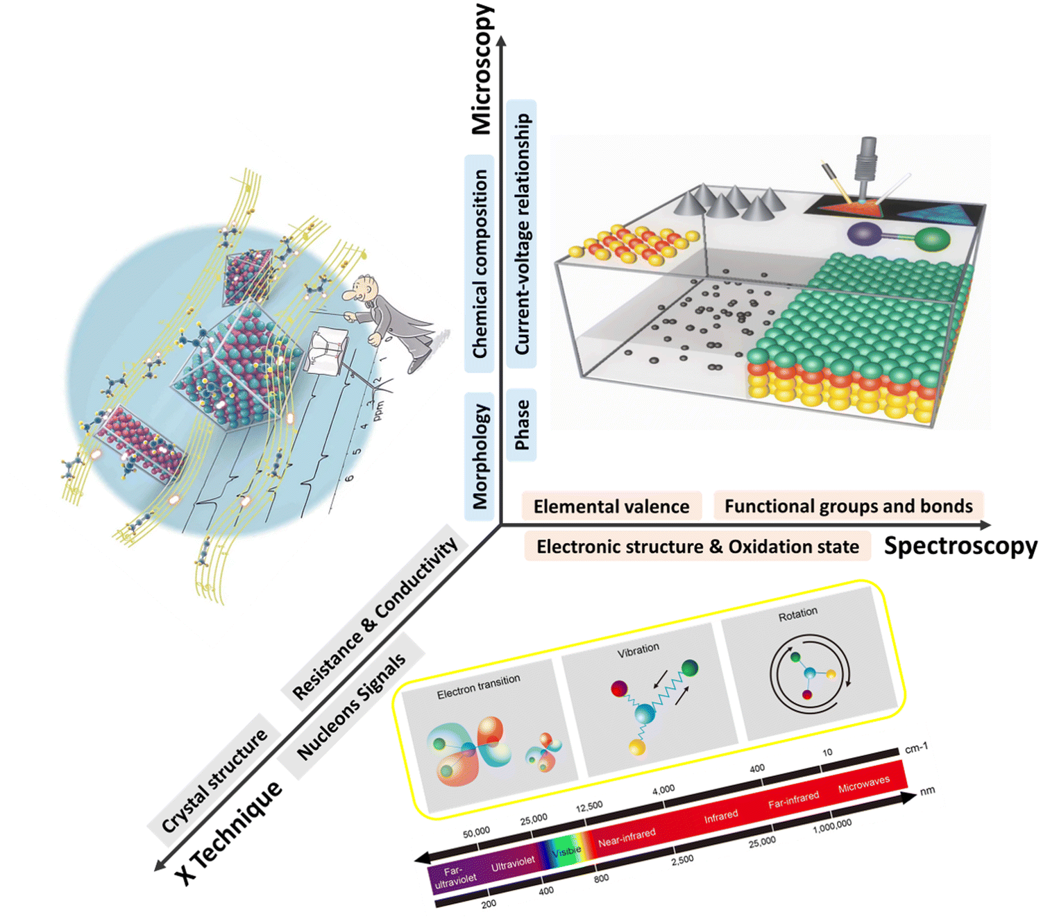 | ||
| Scheme 1 In situ techniques to visualise the electrode/electrolyte interface and electrocatalysts under operating conditions. | ||
2. Microscopic characterisation techniques
Microscopic characterisation enables the visualisation of electrified interfaces at the molecular/atomic scale, which could relate catalysis performances with electrocatalytically active microstructures. This relation further serves as the basis for the rational design of next-generation electroactive materials. In the past few years, in situ mapping microscopy has witnessed significant progress, and has been widely applied for the investigation of dynamic changes of electrode materials under working conditions.16,19,20,26–282.1. Electronic microscopy
Electronic microscopy methods generally consist of an accelerated electron beam (high-voltage electrons with an energy of 5–100 keV from a heated tungsten or field emission filament) and a signal detector, operating at scanning, transmission, or scanning transmission modes. Implementing these characterisation tools at an electrified interface enables the in situ or operando track of morphological transformation, physical migration, and phase evolution of electrocatalysts under operating conditions, thus offering unique insights into the structural dynamics of functional materials and reaction pathways of targeted processes.26,29Such insights have greatly advanced mechanistic understanding and established more reliable structure–performance relationships towards CO2RR on Cu-based electrocatalysts. In situ scanning transmission electron microscopy (STEM) was used to image the dynamic morphological transformation of Cu2O cubes under CO2RR conditions.30 The migration of Cu2O cubes and their transformation to dendritic structures as well as dissolution and redeposition of Cu were in situ observed (Fig. 1a), revealing time-dependent dynamic reconstructions of Cu2O cubes. Observing CuO nanosheet catalysts for the same reaction using in situ liquid TEM showed the fragmentation of the nanosheets and further conversion to a stable large dendritic Cu structure (Fig. 1b).31 Both in situ studies demonstrate that Cu catalysts prefer kinetically to form a dendritic morphology under CO2RR working conditions. In situ environmental TEM was utilised to visualise the morphology change of RuO2 nanomaterial decorated carbon nanotube cathodes (CNTs).32 The dynamic expansion and shrinkage of RuO2 spherical particles were tracked during the redox processes (Fig. 1c). A diffusion-controlled kinetics was elucidated by calculating the change of surface area and quantifying the growth rate of particles.
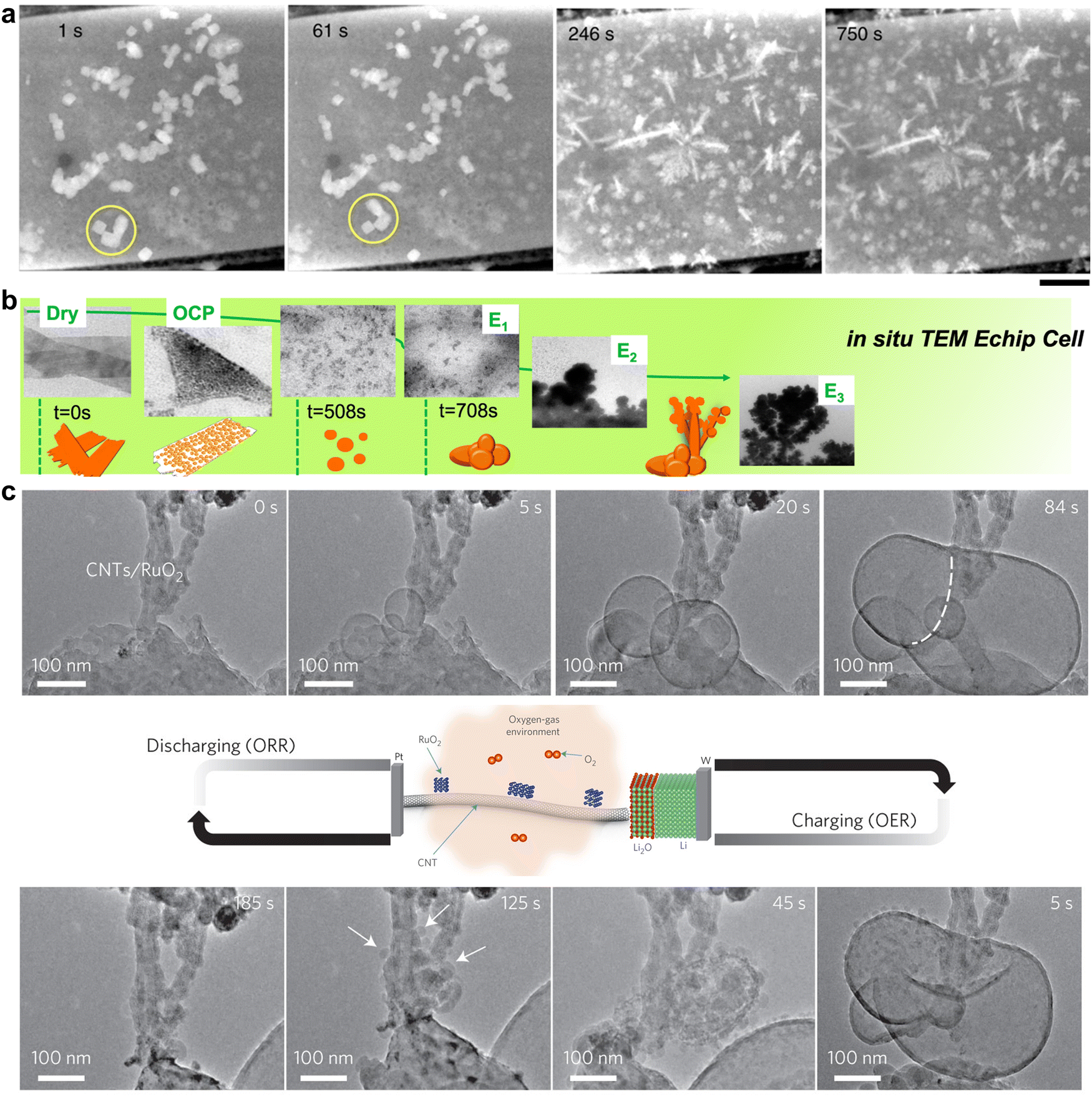 | ||
| Fig. 1 (a) Evolution of Cu2O cubes under reducing conditions at −0.7 V in a CO2-saturated 0.1 M KHCO3 solution imaged by in situ STEM. This figure has been adapted from ref. 30 with permission from SPRINGER NATURE, copyright 2020.30 (b) Real-time imaging of morphology evolution of CuO nanosheet catalysts under CO2RR probed by an in situ TEM Echip flow cell. This figure has been adapted from ref. 31 with permission from SPRINGER NATURE, copyright 2021.31 (c) Time-resolved in situ environmental TEM observation of the CNTs/RuO2 cathode morphological evolution of the discharge–charge products. This figure has been adapted from ref. 32 with permission from SPRINGER NATURE, copyright 2017.32 | ||
Recent intense developments in this field enable compatibility of key in situ set-ups (especially the in situ TEM cells) with ordinary TEMs. Further efforts are needed to overcome challenges related to the highly scattered electron beam and sacrificed resolution under low vacuum conditions needed for real-time in situ characterisation.
2.2. X-Ray microscopy
Compared to electron sources, X-ray beam (soft, tender, or hard X-ray with energy range up to 180 keV) is advantageous in that a high vacuum is not needed for operation. X-Ray beam first penetrates the sample at the desired depth, and then projects onto signal detectors, in either transmission or fluorescence mode.28The operational principle of transmission X-ray microscopy (TXM) is similar to that of optical microscopy, except that the former uses hard X-rays, instead of visible light, to illuminate the samples.23,28,33 TXM is a full-field imaging technique, and the spatial resolution is typically 20–30 nm. The highly penetrative, non-destructive hard X-ray beam and the high flux of synchrotron X-ray sources together render TXM suitable for in situ/operando characterisation. A typical in situ TXM technique is X-ray tomography measurement, which takes projections of a rotating sample at each fraction of a degree. The 2D images collected at all angles are then assembled into a 3D image, thus delivering a 3D structure with morphological information of the sample. For example, it was utilised to monitor the domain of local cathode catalyst degradation in fuel cells during voltage cycling (Fig. 2a).34
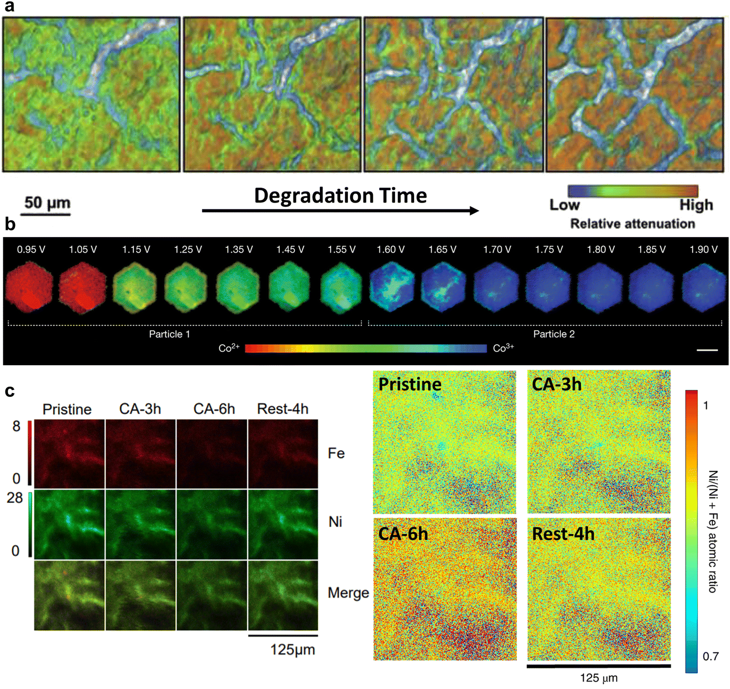 | ||
| Fig. 2 (a) Degradation of a cathode catalyst layer in a membrane electrode assembly captured by operando XTM. This figure has been adapted from ref. 34 with permission from ELSEVIER, copyright 2017.34 (b) Steady-state voltage-dependent Co oxidation state phase maps of β-Co(OH)2 particles via operando STXM. This figure has been adapted from ref. 24 with permission from SPRINGER NATURE, copyright 2021.24 (c) Ni and Fe elemental distribution evolution during the OER visualised by synchrotron XFM. The atomic ratio of Ni/(Ni + Fe) increased gradually with continuous anodic polarization, reflecting reversibility of phase segregation and a dynamic dissolution and redeposition of Fe between charged and open-circled conditions. This figure has been adapted from ref. 25 with permission from SPRINGER NATURE, copyright 2020.25 | ||
Scanning transmission X-ray microscopy (STXM) employs a focused X-ray beam to scan across the sample and builds up a microscopic image by recording the transmission X-ray intensity of each scanning area. It is widely adopted within the soft X-ray range because it is easier to fabricate the high-resolution (typically 12–40 nm) optics, and is thus suitable for mapping light elements, e.g., carbon and oxygen. In a recent study, operando STXM was used to obtain a 50 nm spatially resolved phase map of the Co oxidation state at the Co LIII-edge across a platelet-like OER model catalyst.24 The heterogeneity of oxidation state has been observed within a single nanoparticle during the OER process. The higher oxidation state is preferentially located in the interior of the materials, while lower oxidation state is easy to be detected in the edge (Fig. 2b). However, the STXM image is typically built up pixel-by-pixel by rasterizing the X-ray beam across the sample, which however requires a long acquisition time, limiting its wide applications to the in situ characterisation of transient changes of catalysts under operating conditions.
Owing to its low noise, high sensitivity, and high transmittance, X-ray fluorescence microscopy (XFM) can be used to quantitatively analyse specific elements, thus enabling the monitoring of phase segregation and structural evolution under electrochemical processes of interest.35 Synchrotron XFM was used to unravel the reversible phase separation in mixed Ni–Fe hydroxide electrocatalysts during the OER by imaging the evolution of metal distribution and concentration (Fig. 2c).25
2.3. Force based microscopies
Force based microscopy employs a tip to probe and scan across sample surfaces with superior scanning accuracy and it is based on the attractive forces between the tip and the surface. It allows for the tracking of electrocatalyst morphologies and adsorbate-induced reconstruction under operating conditions.Atomic force microscopy (AFM) is widely adopted to collect atomic-resolution pictures of targeted surfaces for diverse applications.39In situ electrochemical AFM (EC-AFM) was used to dynamically monitor the morphological evolution of Cu nanocubes under CO2RR conditions by Cuenya's group (Fig. 3a).36 The observed formation of cracks and surface roughening using EC-AFM were linked to the change of Cu oxidation state and lowered selectivity of C2+ products. Similar EC-AFM was also used to study the effect of subsurface oxygen in Cu-based electrocatalysts on performance of CO2RR (Fig. 3b).37 Complemented by other time-dependent characterisation methods, surface morphology and roughness of polycrystalline Cu and thick Cu2O were not dominant factors in the C2+ production rate. The catalysts of β-Co(OH)2 for the OER gradually underwent structural and phase changes to expanded α-CoO2H1.5·0.5H2O, and then a stabilized β-CoOOH structure (Fig. 3c). Operando EC-AFM was also used to monitor this detailed transformation process as well as the dynamics of local heterogeneity in β-Co(OH)2 particles.24
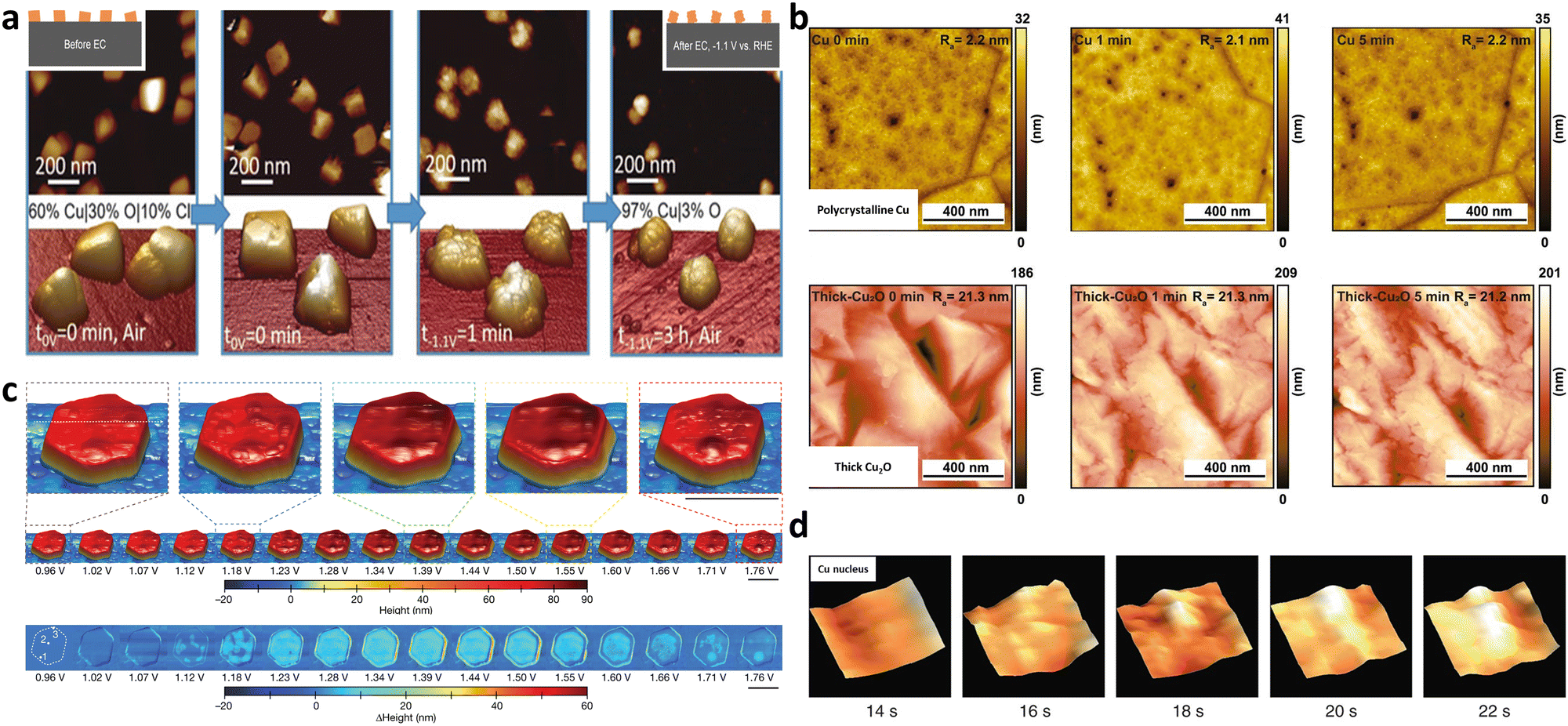 | ||
| Fig. 3 (a) Dynamic morphological changes of Cu nanocubes during CO2RR using in situ EC-AFM in a CO2-saturated 0.1 M KHCO3 aqueous solution. Cracks were observed to form on the (100) facets of Cu nanocubes, which was ascribed to the mechanical stress due to the removal of Cl− ions (introduced by the electrodeposition of Cu cubes) from the cubes. This figure has been adapted from ref. 36 with permission from Wiley-VCH, copyright 2018.36 (b) Monitoring surface topography or roughness over polycrystalline Cu and thick Cu2O under CO2RR using quasi in situ EC-AFM in 0.1 M CO2-saturated K2CO3 electrolyte (pH 7) at −0.8 VRHE. This figure has been adapted from ref. 37 with permission from NATIONAL ACAFEMY OF SCIENCES, copyright 2021.37 (c) This figure has been adapted from ref. 24 with permission from SPRINGER NATURE, copyright 2021.24 (d) Birth and growth of a copper nucleus (46 × 46 nm2 cropped regions) via in situ high speed LMFM. This figure has been adapted from ref. 38 with permission from SPRINGER NATURE, copyright 2017.38 | ||
Another typical force-based microscopy is the lateral molecular force microscopy (LMFM). It is a kind of uncontacted technique based on the optical vertical feedback mechanism, possessing exceptional spatial-temporal resolution. Operando high-speed LMFM technique with vertically oriented probes was first used by the Fermín group in 2017, to track the stochastic Cu nucleation process on indium tin oxide (ITO) by detecting the local hydration layer fluctuation in real time (Fig. 3d).38 Powerfully, the detailed evolution of materials can be captured and presented in the form of a real-time video.
2.4. Electrochemical microscopy
Electrochemical microscopy is functioned based on the collection and differentiation of locally site-dependent electrochemical responses. Two prevalent electrochemical microscopies are scanning electrochemical microscopy (SECM) and scanning electrochemical cell microscopy (SECCM).40–44SECM basically consists of four components: an ultramicroelectrode as the SECM tip, a position controller for accurate probe movement, a bipotentiostat to control the current-potential, and a data acquisition system (Fig. 4a).27,45 Recently, SECM was used to probe the local pH of an electrified interface. With a modified gold ultramicroelectrode as the probe in SECM, Koper and co-workers measured the interfacial pH at a fixed distance from the electrode during CO2RR, revealing a pH-buffering region due to the reversible switch of CO2 and HCO3−.48 Currently, SECM is mainly constrained by the low spatial resolution which was determined by the tip dimensions.49,50
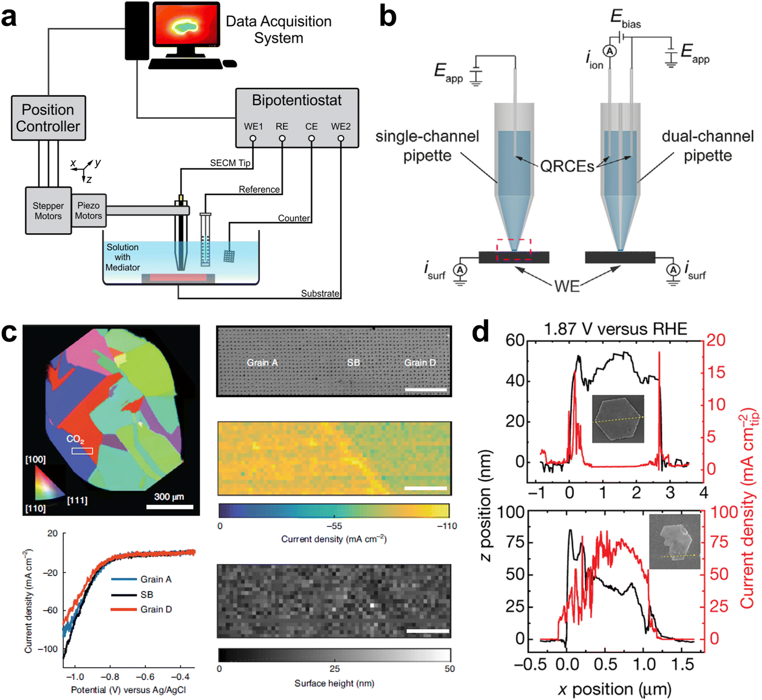 | ||
| Fig. 4 (a) Schematic of a SECM instrument. This figure has been adapted from ref. 45 with permission from AMERICAN CHEMICAL SOCIETY, copyright 2016.45 (b) Schematic of SECCM with a single-channel and dual-channel pipette probe. This figure has been adapted from ref. 46 with permission from WILEY-VCH, copyright 2021.46 (c) Microstructural origin of locally enhanced CO2RR activity on gold electrode grain boundaries via SECCM. This figure has been adapted from ref. 47 with permission from SPRINGER NATURE, copyright 2021.47 (d) SECCM of bulk redox transformations and the OER activity of β-Co(OH)2 particles. This figure has been adapted from ref. 24 with permission from SPRINGER NATURE, copyright 2021.24 | ||
SECCM is a scanning-droplet-based technique equipped with a mobile meniscus cell, which controls the potential bias between quasi-reference electrodes in the barrel and collects current response across the liquid meniscus formed at the end of the pipette (Fig. 4b).46,51,52 This configuration allows for tracking the surface topography and activity simultaneously with a more stable response and higher spatiotemporal resolution than SECM. In situ high-resolution SECCM equipped with a 200 nm diameter tip has been used to record spatially resolved videos of the CO2RR and HER by Unwin and co-workers and the role of grain boundaries in CO2RR was elucidated (Fig. 4c).47 More recently, SECCM with a 440 nm diameter nanopipette tip was utilised to visualise the OER activity of β-Co(OH)2, associating local activity and bulk reaction (Fig. 4d).24
3. Spectroscopic characterisation techniques
While microscopic techniques are commonly used for investigating the dynamic transformation in materials shape and morphology, spectroscopic techniques are able to provide more chemical information that is critical to identifying intermediates/products and exploring reaction mechanisms.15,22 Spectroscopic characterisations focus on the evolution of molecular and atomic properties, e.g., chemical states, and electronic structures, of involved reactants, intermediates, and products. Such information is crucial to revealing thermodynamic and kinetic parameters of any electrochemical process.53,543.1. X-Ray based spectroscopic techniques
X-Ray absorption spectroscopy (XAS) is one of the most widely used X-ray spectroscopic techniques in in situ electrocatalysis. XAS can be divided into two absorption regions: X-ray absorption near-edge structure (XANES) is sensitive to the electron transition from occupied to unoccupied orbital, thus providing the information of the local symmetry and the oxidation state; while extended X-ray absorption fine structure (EXAFS) reflects the coordination between the core and the nearby atoms, thus providing the information of coordination number and distance between the core and the neighbouring atoms. The X-rays generated through synchrotron radiation are usually involved because of their high brightness, wide energy range and coherence of synchrotron X-rays. This offers the capability of probing interface molecular and electronic structures as well as charge transfers under a working status.22,55–57In recent years, operando or in situ hard XAS has been widely used to monitor the dynamic change of electrocatalysts at the nanoscale. For instance, an active CuX–CuN3 cluster which only exists under electrochemical reducing conditions was identified by operando XAS and its presence led to a high ethanol selectivity in CO2RR (Fig. 5a).58Operando/in situ soft XAS is more sensitive to investigate the oxidation, aggregation and deactivation mechanisms of electrodes during electrochemistry processes. Compared with hard XAS, soft XAS with lower energy provides more horizon of the d orbital of the materials. Due to forbidden bipolar, the excitation of electron from 1s to 3d orbital is not allowed with hard X-ray excitation whereas the electrons in the 2p orbital can be directly excited via soft X-ray to fill the 3d unoccupied orbital. A high-resolution spectrum with low-energy excitation can be detected to amplify the measurement of atomic structure changing of transition metals. Wu et al. used in situ soft XAS to investigate the oxidation state of the Cu electrode during the CO2RR, and the co-existence of Cu(I) and Cu(0) was found in an electrochemically processed Cu (Fig. 5b and c), further establishing the relationship between the Cu(I)/Cu(0) species and the C2 product selectivity.59
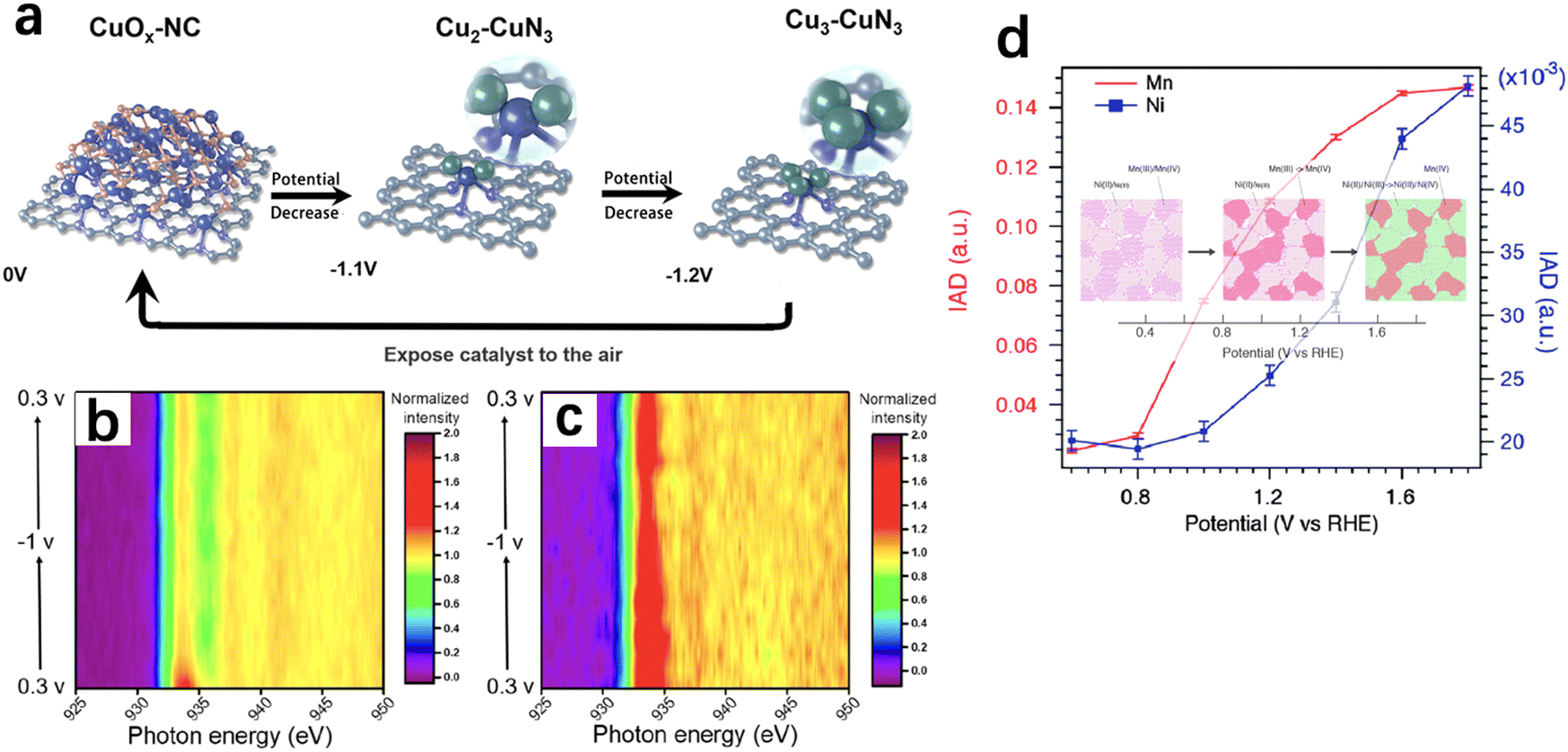 | ||
| Fig. 5 (a) Proposed scheme for the reversible formation of the catalytically active CuX–CuN3 cluster based on operando XAS (rufous, O; grey, C; purple, N; blue, Cu bond to both N and Cu; green, Cu just bond to Cu). This figure has been adapted from ref. 58 with permission from SPRINGER NATURE, copyright 2022.58 Contour plots of in situ Cu LIII-edge XAS of the (b) as-prepared Cu and (c) CV-treated Cu cycled between 0.3 and −1 V. In situ Cu LIII-edge XAS were collected in total fluorescence yield mode. This figure has been adapted from ref. 59 with permission from AMERICAN CHEMICAL SOCIETY, copyright 2020.59 (d) Absolute values of integrated spectral differences using the XES spectrum at 0.4 V as the reference and images of sequential phase transitions upon changing potential. This figure has been adapted from ref. 60 with permission from ROYAL SOCIETY OF CHEMISTRY, copyright 2015.60 | ||
X-Ray emission spectroscopy (XES) is a kind of photon-in and photon-out spectroscopy in which a core electron is excited by an incident X-ray photon to its excited state and then decays by emitting an X-ray photon to fill the core hole. XES is useful to track electronic structures. For example, a wavelength dispersive multi-crystal spectrometer was used to collect operando XES signals from multiple elements simultaneously and the images of local structure and oxidation state around Mn and Ni in a Ni-doped MnOx ORR/OER bifunctional catalyst were visualised (Fig. 5d).60
There is no doubt that X-ray spectroscopy techniques play a crucial role in identifying local geometric and electronic structure of solids. Two challenges remain: first, the synchrotron radiation at high dosage imposes unavoidable and unreversible damage to materials under examination; second, it is challenging for the detection and monitoring of adsorption of reactants or generation of gas or liquid intermediates/products, which are usually present in trace amounts or reside at the solid/gas or solid/liquid interfaces.
3.2. Optical spectroscopies
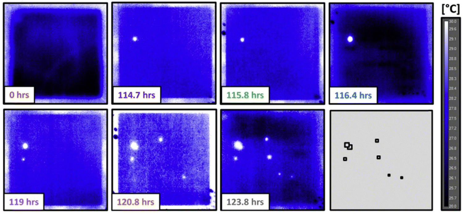
In contrast to X-ray, optical light is a kind of non-ionising radiation with a wavelength ranging from 10 nm (ultra-violet) to 1 mm (far-infrared, far-IR). Two main tools, infrared (IR) spectroscopy and Raman spectroscopy, have been reported for localised studying bond break/formation, electron/proton transfer and adsorbed species at electrochemical reaction interfaces, which are complementary tools to uncover and verify reaction mechanisms.16,61,62In situ IR spectroscopy is one of the most widely used techniques for surface analysis, including revealing active sites, tracing surface structures and adsorbed species at the molecular level. However, IR is susceptible to water and is difficult to access the low wavenumber region, in which rich information of hydroxy groups, oxygen species, and metal–molecule bonds on surfaces are present.63,64In situ Raman spectroscopy is an effective and precise technique used to study catalyst evolution and adsorbed species on the catalyst surface in aqueous systems due to its low scattering and cross-section for water adsorption. Compared to IR spectroscopy, Raman spectroscopy can collect vibration signals at low wavenumber region, while the low scattering of water limits the time-resolution. Although surface-enhanced Raman spectroscopy (SERS) has been employed to improve the sensitivity for higher signal noise ratio, it is restricted to a few metals (primarily Au, Ag, and Cu) with rough surfaces or nanostructures.65,66 As an example, in Bender's group, the impact of bare spots (harmful defects and harmless coating irregularities) on the lifetime of cathodic electrodes in proton exchange membrane fuel cells was identified via quasi in situ IR thermography.67 Analysed by the IR thermal map, hydrogen crossover was observed on several failure point locations (Fig. 6). Furthermore, the lifetime of membrane electrode assembly cells was strongly linked to the position of irregularities, especially with a dramatic decrease located at the electrode inlet region.
 | ||
| Fig. 6 IR thermography capturing the onset of failure for a pristine membrane electrode assembly operated in the counterflow configuration. This figure has been adapted from ref. 67 with permission from ELSEVIER, copyright 2018.67 | ||
4. Other characterisation approaches
In addition to microscopic and spectroscopic characterisations, other techniques have been developed and applied in in situ characterisation of electrified interfaces using methods such as X-ray powder diffraction (XRD),56 NMR, electrogenerated chemiluminescence (ECL), and electrochemical impedance spectroscopy (EIS).68Conducting XRD under electrochemical conditions can be used to monitor structural dynamics of electrocatalysts (typically in crystalline phase), particularly in terms of phase transition, atomic occupancy, crystallinity degree, and lattice parameters.69–71 By relating these crystalline parameters with the corresponding electrocatalytic performance (selectivity, activity and stability), it enables the identification of real reactive sites and prediction of more promising electrocatalytic structures.69
NMR is sensitive to the magnetic properties of the atomic nuclei that absorb electromagnetic radiation, and thus provides information about nuclear spins and their surroundings. This enables operando NMR to track reactants, products, environmental molecules and even reaction intermediates during electrolysis. For example, Mustarelli's group used operando electrochemical NMR as a diagnostic method to monitor the evolution of protons in PEMFCs by tracking the 1H zero time echo images72 (ZTE, Fig. 7a). Although in situ NMR cannot differentiate protons originating from water or phosphoric acid, it opens the possibility of investigating water and other small-molecule products, such as methanol, ethanol, ethylene, etc. in electrochemical devices.73,74 Further efforts in advancing operando NMR lie in developing high-resolution magic angle spinning NMR approaches, differentiating various signals in static NMR experiments, and synchronising NMR with electrochemical responses.
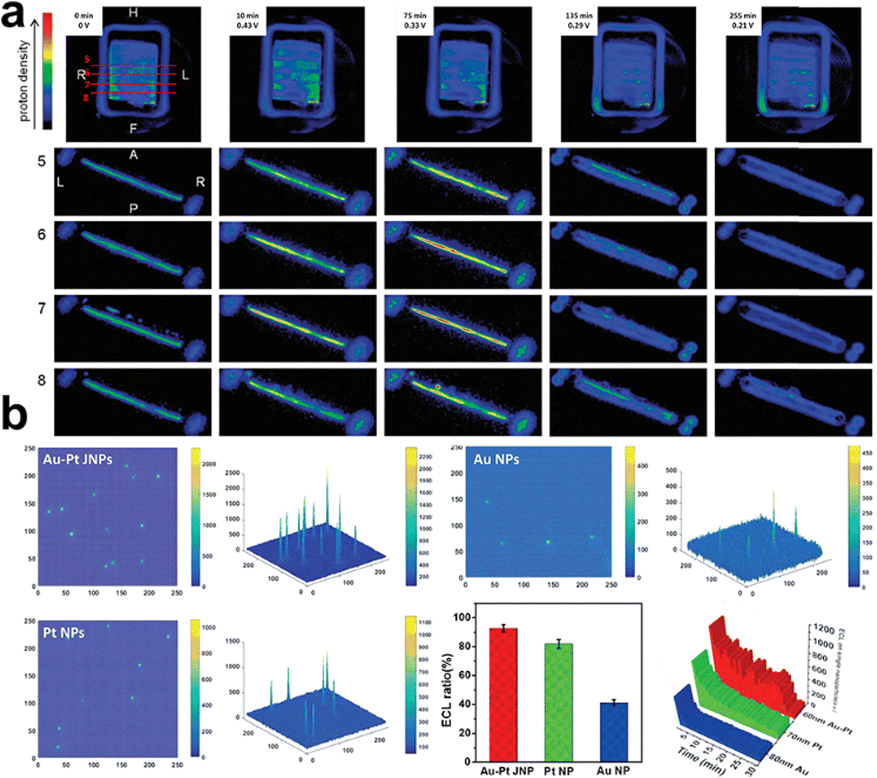 | ||
| Fig. 7 (a) 1H ZTE images and axial slices extracted from the corresponding 3D dataset obtained from the PBI_5N fuel cell operating at 47 degrees. During operation the current was maintained constant at 5 mA. This figure has been adapted from ref. 72 with permission from ROYAL SOCIETY OF CHEMISTRY, copyright 2015.72 (b) 2D and 3D ECL intensity diagrams of Au–Pt JNPs, Pt NPs, and Au NPs. This figure has been adapted from ref. 77 with permission from WILEY-VCH, copyright 2018.77 | ||
ECL, also known as electrochemiluminescence, is a kind of emission of photons from luminophore following an electron transfer process triggered by an electrochemical reaction.75 This technique can help understand complex mechanisms where leads to the electrochemical generation of light in a visible fashion.76 Xu and co-workers visualised the luminophore evolution on monometallic Au, Pt, and double-faced Au–Pt Janus nanoparticles using the ECL approach.77 Optical information of reactant catalytic activity can be directly read out when the luminophores (e.g., Ru(bpy)32+) react on the surface of the electrode and produce emissive excited-state products. Recording the ECL emission ratio in the local redox reaction, time-resolved 2D and 3D ECL intensities were imaged on these nanoparticles, showing the lifetime stability and electrochemical activity (Fig. 7b).
5. Conclusions and outlook
Operando/in situ characterisation techniques have facilitated the understanding of not only the final/steady status of electrocatalytic reactions but also the connection of catalyst structural evolutions with electrocatalytic performances. They can be used to construct the dynamic structure–activity relationship, identify active structures and origin of local active centres, and clarify reaction pathways in the electrocatalysis process. There are some limitations owing to inherent challenges related to the limited in situ equipment setup, dimension of observation windows, time resolution, and the measuring environment.Instrument setup and time resolution
Real-time characterisation is desirable for electrocatalytic processes because of the fast kinetic nature: elementary reactions involved with key intermediates can be completed from milliseconds to seconds. It is difficult for most existing structural and product analysis equipment to achieve such fast time scales, and special designs of in situ electrochemical cells add complexity to the quality of signals and time resolution. It is necessary to develop an all-purpose in situ reactor for multimodal characterisation, which is compatible with different beamlines/signals simultaneously. In terms of time resolution, not only ultrafast studies within hundreds of picoseconds that rely on improvement of pump-and-probe approach and synchrotron equipment should be explored, but longer time scales also should be emphasised for studying the degradation and consumption of catalytic systems that are relevant to real-world applications.Complementary techniques (microscopy–spectroscopy–X)
Despite these remarkable examples for in situ/operando characterisation, single approach is still difficult to obtain the full picture of the mechanism of an electrochemical reaction. This shortfall can be overcome by complementing multiple techniques, providing multidimensional information simultaneously with high spatial and time resolution. Recently, few such examples have been demonstrated to track in real time the whole picture of electrochemical process including the electrode, intermediates, and products. There is growing interest in combining microscopy, spectroscopy, and next-gen X technology as novel tools to open new characterisation ways.Data analysis
Microscopy cameras are fast evolving to enhance the quality of acquired images and videos. Along with these improvements is a concomitant increase in the associated data size. For instance, a Gatan K3 IS can produce up to 150 frames per second at full resolution, which means that a 20-MB frame image would increase to around 200 GB for a one-minute video, meaning that TB-size data for a single in situ TEM investigation can be easily generated. There needs to be a clear strategy for data storage, transferring and processing – the latter now typically requires high-performance computing.78AI or ML assisted modelling and simulation
Nowadays, to solve complex problems or use abundant data feed to imitate, artificial intelligence (AI) and machine learning (ML) are computed-based technologies to simulate the human mind and ways of thinking. AI/ML potentials constitute a promising approach to solve computationally challenging problems in electrocatalysis field,79,80 such as automatic robotic chemist,81 CO2 and H2 electrocatalyst discovery,82,83 spinel oxide covalency competition analysis,84 and molecular crystal structure prediction.85 It is known that the current characterisation technique is still limited by accuracy and time/spatial interval. Operando/in situ collected data could be used to feed and train AI and ML models, predicting undetected time and region intervals to depict the reaction mechanism diagram. It remains some open questions: how to select a series of accurate data (also how to define data precision, data accuracy) to feed into the model, how to use limited data to construct a trustworthy model, and how to deal with high-throughput data generated from in situ characterisation.Conflicts of interest
There is no conflict to declare.Acknowledgements
F. L. is grateful for his Australian Research Council Discovery Early Career Researcher Award (project number DE200100477) funded by the Australian Government. This research was supported by an AINSE Ltd Early Career Researcher Grant (ECRG).References
- C. Hepburn, E. Adlen, J. Beddington, E. A. Carter, S. Fuss, N. Mac Dowell, J. C. Minx, P. Smith and C. K. Williams, Nature, 2019, 575, 87–97 CrossRef CAS PubMed.
- R. A. Tufa, D. Chanda, M. Ma, D. Aili, T. B. Demissie, J. Vaes, Q. Li, S. Liu and D. Pant, Appl. Energy, 2020, 277, 115557 CrossRef CAS.
- Z. W. Seh, J. Kibsgaard, C. F. Dickens, I. Chorkendorff, J. K. Norskov and T. F. Jaramillo, Science, 2017, 355, eaad4998 CrossRef PubMed.
- O. S. Bushuyev, P. De Luna, C. T. Dinh, L. Tao, G. Saur, J. van de Lagemaat, S. O. Kelley and E. H. Sargent, Joule, 2018, 2, 825–832 CrossRef CAS.
- R. I. Masel, Z. Liu, H. Yang, J. J. Kaczur, D. Carrillo, S. Ren, D. Salvatore and C. P. Berlinguette, Nat. Nanotechnol., 2021, 16, 118–128 CrossRef CAS PubMed.
- Q. Meyer, Y. Zeng and C. Zhao, Adv. Mater., 2019, 31, e1901900 CrossRef PubMed.
- S. Zhang, X. Jing, Y. Wang and F. Li, ChemNanoMat, 2021, 7, 728–736 CrossRef CAS.
- Y. Wang, C. Wang, M. Li, Y. Yu and B. Zhang, Chem. Soc. Rev., 2021, 50, 6720–6733 RSC.
- K. Zhu, X. Zhu and W. Yang, Angew. Chem., Int. Ed., 2019, 58, 1252–1265 CrossRef CAS PubMed.
- D. D. Zhu, J. L. Liu and S. Z. Qiao, Adv. Mater., 2016, 28, 3423–3452 CrossRef CAS PubMed.
- H. Jin, C. Guo, X. Liu, J. Liu, A. Vasileff, Y. Jiao, Y. Zheng and S. Z. Qiao, Chem. Rev., 2018, 118, 6337–6408 CrossRef CAS PubMed.
- S. Zhang, C. Chen, K. Li, H. Yu and F. Li, J. Mater. Chem. A, 2021, 9, 18785–18792 RSC.
- Y. Jiao, Y. Zheng, M. Jaroniec and S. Z. Qiao, Chem. Soc. Rev., 2015, 44, 2060–2086 RSC.
- Y. Zhang, S.-X. Guo, X. Zhang, A. M. Bond and J. Zhang, Nano Today, 2020, 31, 100835 CrossRef CAS.
- Y. Zhu, J. Wang, H. Chu, Y.-C. Chu and H. M. Chen, ACS Energy Lett., 2020, 5, 1281–1291 CrossRef CAS.
- A. D. Handoko, F. Wei, Jenndy, B. S. Yeo and Z. W. Seh, Nat. Catal., 2018, 1, 922–934 CrossRef CAS.
- K. Chan, Nat. Commun., 2020, 11, 5954 CrossRef CAS PubMed.
- J. E. Huang, F. Li, A. Ozden, A. Sedighian Rasouli, F. P. Garcia de Arquer, S. Liu, S. Zhang, M. Luo, X. Wang, Y. Lum, Y. Xu, K. Bertens, R. K. Miao, C. T. Dinh, D. Sinton and E. H. Sargent, Science, 2021, 372, 1074–1078 CrossRef CAS PubMed.
- J. Li and J. Gong, Energy Environ. Sci., 2020, 13, 3748–3779 RSC.
- F. Meirer and B. M. Weckhuysen, Nat. Rev. Mater., 2018, 3, 324–340 CrossRef.
- T. Xia, Z. Wang and F. Li, Curr. Opin. Electrochem., 2022, 31, 100846 CrossRef CAS.
- J. Timoshenko and B. Roldan Cuenya, Chem. Rev., 2021, 121, 882–961 CrossRef CAS PubMed.
- X. Zhou, J. Dong, Y. Zhu, L. Liu, Y. Jiao, H. Li, Y. Han, K. Davey, Q. Xu, Y. Zheng and S. Z. Qiao, J. Am. Chem. Soc., 2021, 143, 6681–6690 CrossRef CAS PubMed.
- J. T. Mefford, A. R. Akbashev, M. Kang, C. L. Bentley, W. E. Gent, H. D. Deng, D. H. Alsem, Y. S. Yu, N. J. Salmon, D. A. Shapiro, P. R. Unwin and W. C. Chueh, Nature, 2021, 593, 67–73 CrossRef CAS PubMed.
- C. Kuai, Z. Xu, C. Xi, A. Hu, Z. Yang, Y. Zhang, C.-J. Sun, L. Li, D. Sokaras, C. Dong, S.-Z. Qiao, X.-W. Du and F. Lin, Nat. Catal., 2020, 3, 743–753 CrossRef CAS.
- Z. Fan, L. Zhang, D. Baumann, L. Mei, Y. Yao, X. Duan, Y. Shi, J. Huang, Y. Huang and X. Duan, Adv. Mater., 2019, 31, e1900608 CrossRef PubMed.
- L. I. Stephens, N. A. Payne and J. Mauzeroll, Anal. Chem., 2020, 92, 3958–3963 CrossRef CAS PubMed.
- C. Cao, M. F. Toney, T.-K. Sham, R. Harder, P. R. Shearing, X. Xiao and J. Wang, Mater. Today, 2020, 34, 132–147 CrossRef CAS.
- J. Li, G. Johnson, S. Zhang and D. Su, Joule, 2019, 3, 4–8 CrossRef.
- R. M. Aran-Ais, R. Rizo, P. Grosse, G. Algara-Siller, K. Dembele, M. Plodinec, T. Lunkenbein, S. W. Chee and B. R. Cuenya, Nat. Commun., 2020, 11, 3489 CrossRef CAS PubMed.
- X. Wang, K. Klingan, M. Klingenhof, T. Moller, J. Ferreira de Araujo, I. Martens, A. Bagger, S. Jiang, J. Rossmeisl, H. Dau and P. Strasser, Nat. Commun., 2021, 12, 794 CrossRef CAS PubMed.
- L. Luo, B. Liu, S. Song, W. Xu, J. G. Zhang and C. Wang, Nat. Nanotechnol., 2017, 12, 535–539 CrossRef CAS PubMed.
- E. de Smit, I. Swart, J. F. Creemer, G. H. Hoveling, M. K. Gilles, T. Tyliszczak, P. J. Kooyman, H. W. Zandbergen, C. Morin, B. M. Weckhuysen and F. M. de Groot, Nature, 2008, 456, 222–225 CrossRef CAS PubMed.
- R. T. White, A. Wu, M. Najm, F. P. Orfino, M. Dutta and E. Kjeang, J. Power Sources, 2017, 350, 94–102 CrossRef CAS.
- T. Ohigashi, T. Aota, N. Watanabe, H. Takano, H. Yokosuka and S. Aoki, Jpn. J. Appl. Phys., 2008, 47, 4742–4745 CrossRef CAS.
- P. Grosse, D. Gao, F. Scholten, I. Sinev, H. Mistry and B. Roldan Cuenya, Angew. Chem., Int. Ed., 2018, 57, 6192–6197 CrossRef CAS PubMed.
- G. Liu, M. Lee, S. Kwon, G. Zeng, J. Eichhorn, A. K. Buckley, F. D. Toste, W. A. Goddard, 3rd and F. M. Toma, Proc. Natl. Acad. Sci. U. S. A., 2021, 118, e2012649118 CrossRef CAS PubMed.
- R. L. Harniman, D. Plana, G. H. Carter, K. A. Bradley, M. J. Miles and D. J. Fermin, Nat. Commun., 2017, 8, 971 CrossRef PubMed.
- X. Shi, W. Qing, T. Marhaba and W. Zhang, Electrochim. Acta, 2020, 332, 135472 CrossRef CAS.
- Y. Li, X. Ning, Q. Ma, D. Qin and X. Lu, Trends Anal. Chem., 2016, 80, 242–254 CrossRef CAS.
- Y. Liang, J. H. K. Pfisterer, D. McLaughlin, C. Csoklich, L. Seidl, A. S. Bandarenka and O. Schneider, Small Methods, 2019, 3, 1800387 CrossRef.
- C. L. Bentley, J. Edmondson, G. N. Meloni, D. Perry, V. Shkirskiy and P. R. Unwin, Anal. Chem., 2019, 91, 84–108 CrossRef CAS PubMed.
- C. L. Bentley, M. Kang and P. R. Unwin, J. Am. Chem. Soc., 2019, 141, 2179–2193 CrossRef CAS PubMed.
- T. Kai, C. G. Zoski and A. J. Bard, Chem. Commun., 2018, 54, 1934–1947 RSC.
- D. Polcari, P. Dauphin-Ducharme and J. Mauzeroll, Chem. Rev., 2016, 116, 13234–13278 CrossRef CAS PubMed.
- C. L. Bentley, Electrochem. Sci. Adv., 2021, 2, e2100081 Search PubMed.
- R. G. Mariano, M. Kang, O. J. Wahab, I. J. McPherson, J. A. Rabinowitz, P. R. Unwin and M. W. Kanan, Nat. Mater., 2021, 20, 1000–1006 CrossRef CAS PubMed.
- M. C. O. Monteiro, A. Mirabal, L. Jacobse, K. Doblhoff-Dier, S. C. Barton and M. T. M. Koper, JACS Au, 2021, 1, 1915–1924 CrossRef CAS PubMed.
- C. L. Bentley, M. Kang and P. R. Unwin, Curr. Opin. Electrochem., 2017, 6, 23–30 CrossRef CAS.
- O. J. Wahab, M. Kang and P. R. Unwin, Curr. Opin. Electrochem., 2020, 22, 120–128 CrossRef CAS.
- P. R. Unwin, A. G. Guell and G. Zhang, Acc. Chem. Res., 2016, 49, 2041–2048 CrossRef CAS PubMed.
- Y. Takahashi, A. Kumatani, H. Shiku and T. Matsue, Anal. Chem., 2017, 89, 342–357 CrossRef CAS PubMed.
- L. Lukashuk and K. Foettinger, Johnson Matthey Technol. Rev., 2018, 62, 316–331 CrossRef CAS.
- V. VM and G. Nageswaran, Front. Chem., 2020, 8, 23 CrossRef PubMed.
- C. Baeumer, J. Appl. Phys., 2021, 129, 170901 CrossRef CAS.
- C.-J. Chang, Y. Zhu, J. Wang, H.-C. Chen, C.-W. Tung, Y.-C. Chu and H. M. Chen, J. Mater. Chem. A, 2020, 8, 19079–19112 RSC.
- A. Vasileff, Y. Zhu, X. Zhi, Y. Zhao, L. Ge, H. M. Chen, Y. Zheng and S. Z. Qiao, Angew. Chem., Int. Ed., 2020, 59, 19649–19653 CrossRef CAS PubMed.
- X. Su, Z. Jiang, J. Zhou, H. Liu, D. Zhou, H. Shang, X. Ni, Z. Peng, F. Yang, W. Chen, Z. Qi, D. Wang and Y. Wang, Nat. Commun., 2022, 13, 1322 CrossRef CAS PubMed.
- T.-C. Chou, C.-C. Chang, H.-L. Yu, W.-Y. Yu, C.-L. Dong, J.-J. Velasco-Vélez, C.-H. Chuang, L.-C. Chen, J.-F. Lee, J.-M. Chen and H.-L. Wu, J. Am. Chem. Soc., 2020, 142, 2857–2867 CrossRef CAS PubMed.
- S. Gul, J. W. Ng, R. Alonso-Mori, J. Kern, D. Sokaras, E. Anzenberg, B. Lassalle-Kaiser, Y. Gorlin, T. C. Weng, P. H. Zwart, J. Z. Zhang, U. Bergmann, V. K. Yachandra, T. F. Jaramillo and J. Yano, Phys. Chem. Chem. Phys., 2015, 17, 8901–8912 RSC.
- E. Perez-Gallent, M. C. Figueiredo, F. Calle-Vallejo and M. T. Koper, Angew. Chem., Int. Ed., 2017, 56, 3621–3624 CrossRef CAS PubMed.
- E. Stavitski and B. M. Weckhuysen, Chem. Soc. Rev., 2010, 39, 4615–4625 RSC.
- Y. Yao, S. Zhu, H. Wang, H. Li and M. Shao, Angew. Chem., Int. Ed., 2020, 59, 10479–10483 CrossRef CAS PubMed.
- P. Wang, H. Yang, C. Tang, Y. Wu, Y. Zheng, T. Cheng, K. Davey, X. Huang and S. Z. Qiao, Nat. Commun., 2022, 13, 3754 CrossRef CAS PubMed.
- M. Zheng, P. Wang, X. Zhi, K. Yang, Y. Jiao, J. Duan, Y. Zheng and S. Z. Qiao, J. Am. Chem. Soc., 2022, 144, 14936–14944 CrossRef CAS PubMed.
- Y. H. Wang, J. B. Le, W. Q. Li, J. Wei, P. M. Radjenovic, H. Zhang, X. S. Zhou, J. Cheng, Z. Q. Tian and J. F. Li, Angew. Chem., Int. Ed., 2019, 58, 16062–16066 CrossRef CAS PubMed.
- A. Phillips, M. Ulsh, K. C. Neyerlin, J. Porter and G. Bender, Int. J. Hydrogen Energy, 2018, 43, 6390–6399 CrossRef CAS.
- M. Lucas and J. F. Boily, Langmuir, 2015, 31, 13618–13624 CrossRef CAS PubMed.
- S.-M. Bak, Z. Shadike, R. Lin, X. Yu and X.-Q. Yang, NPG Asia Mater., 2018, 10, 563–580 CrossRef.
- C. F. Holder and R. E. Schaak, ACS Nano, 2019, 13, 7359–7365 CrossRef CAS PubMed.
- A. V. Llewellyn, A. Matruglio, D. J. L. Brett, R. Jervis and P. R. Shearing, Condens. Matter, 2020, 5, 75 CrossRef CAS.
- A. S. Cattaneo, D. C. Villa, S. Angioni, C. Ferrara, R. Melzi, E. Quartarone and P. Mustarelli, Energy Environ. Sci., 2015, 8, 2383–2388 RSC.
- E. W. Zhao, T. Liu, E. Jonsson, J. Lee, I. Temprano, R. B. Jethwa, A. Wang, H. Smith, J. Carretero-Gonzalez, Q. Song and C. P. Grey, Nature, 2020, 579, 224–228 CrossRef CAS PubMed.
- E. W. Zhao, E. J. K. Shellard, P. A. A. Klusener and C. P. Grey, Chem. Commun., 2022, 58, 1342–1345 RSC.
- A. Fiorani, G. Valenti, M. Iurlo, M. Marcaccio and F. Paolucci, Curr. Opin. Electrochem., 2018, 8, 31–38 CrossRef CAS.
- Irkham, A. Fiorani, G. Valenti, N. Kamoshida, F. Paolucci and Y. Einaga, J. Am. Chem. Soc., 2020, 142, 1518–1525 CrossRef CAS PubMed.
- M. J. Zhu, J. B. Pan, Z. Q. Wu, X. Y. Gao, W. Zhao, X. H. Xia, J. J. Xu and H. Y. Chen, Angew. Chem., Int. Ed., 2018, 57, 4010–4014 CrossRef CAS PubMed.
- S. Tao, M. Li, M. Lyu, L. Ran, R. Wepf, I. Gentle and R. Knibbe, Nano Energy, 2022, 96, 107083 CrossRef CAS.
- N. J. Szymanski, C. J. Bartel, Y. Zeng, Q. Tu and G. Ceder, Chem. Mater., 2021, 33, 4204–4215 CrossRef CAS.
- P. Friederich, F. Hase, J. Proppe and A. Aspuru-Guzik, Nat. Mater., 2021, 20, 750–761 CrossRef CAS PubMed.
- B. Burger, P. M. Maffettone, V. V. Gusev, C. M. Aitchison, Y. Bai, X. Wang, X. Li, B. M. Alston, B. Li, R. Clowes, N. Rankin, B. Harris, R. S. Sprick and A. I. Cooper, Nature, 2020, 583, 237–241 CrossRef CAS PubMed.
- M. Zhong, K. Tran, Y. Min, C. Wang, Z. Wang, C. T. Dinh, P. De Luna, Z. Yu, A. S. Rasouli, P. Brodersen, S. Sun, O. Voznyy, C. S. Tan, M. Askerka, F. Che, M. Liu, A. Seifitokaldani, Y. Pang, S. C. Lo, A. Ip, Z. Ulissi and E. H. Sargent, Nature, 2020, 581, 178–183 CrossRef CAS PubMed.
- K. Tran and Z. W. Ulissi, Nat. Catal., 2018, 1, 696–703 CrossRef CAS.
- Y. Sun, H. Liao, J. Wang, B. Chen, S. Sun, S. J. H. Ong, S. Xi, C. Diao, Y. Du, J.-O. Wang, M. B. H. Breese, S. Li, H. Zhang and Z. J. Xu, Nat. Catal., 2020, 3, 554–563 CrossRef CAS.
- C. Zhao, L. Chen, Y. Che, Z. Pang, X. Wu, Y. Lu, H. Liu, G. M. Day and A. I. Cooper, Nat. Commun., 2021, 12, 817 CrossRef CAS PubMed.
| This journal is © The Royal Society of Chemistry 2023 |