
 Open Access Article
 This Open Access Article is licensed under a Creative Commons Attribution-Non Commercial 3.0 Unported Licence
High conversion continuous flow exfoliation of 2D MoS2†
Thaar M. D.
Alharbi
ab and
Colin L.
Raston
 *b
*b
aPhysics Department, Faculty of Science, Taibah University, Almadinah Almunawarrah, 42353, Saudi Arabia
bFlinders Institute for Nanoscale Science and Technology, College of Science and Engineering, Flinders University, Adelaide SA 5001, Australia. E-mail: colin.raston@flinders.edu.au
First published on 1st November 2023
Abstract
We report a low-cost and highly efficient process for exfoliating of MoS2 using an energy efficient vortex fluidic device (VFD). This method is high in green chemistry metrics in avoiding the use of auxiliary substances, and the process is scalable, with a conversion of as received MoS2 into 2D sheets at ∼73%.
Following the discovery of graphene with its almost limitless applications, attention has recently focused on other two-dimensional (2D) nanomaterials such as transition metal dichalcogenides (TMDs) due also to their unique electronic, optical, optoelectronic, mechanical and catalytic properties.1,2 Of these, molybdenum disulfide (MoS2) is one of the most investigated. The crystal structure of MoS2 consists of sandwiched layers of S–Mo–S with strong covalent bonding in each layer and weak van der Waals interactions between neighbouring layers, and thus there is potential exfoliation of the 2D material.3,4 Indeed exfoliation of bulk MoS2 into few-layered and individual monolayer sheets is crucial for use in a variety of applications. For this, a simple and scalable fabrication technique is required. To date, a variety of approaches have been explored, which include but not limited to liquid phase exfoliation, intercalation, solid state mechanical exfoliation, and chemical vapor deposition.5–7 The above-mentioned methods for preparing such material, which are under batch processing, have some shortcomings including poor control of the exfoliation and difficulty in scaling up. Solid state mechanical exfoliation or liquid-phase exfoliation usually produces nanosheets with a rather broad size distribution and/or are formed in low yield. Intercalation driven exfoliation is time-consuming involving a number of steps.8 Chemical vapor deposition to generate 2D MoS2 operates at high temperature with the material deposited on specific substrates, for example SiO2.9 Coleman et al. have established the use of shear forces in liquids in a commercial kitchen blender to exfoliate MoS2 in the presence of a surfactant as a large-scale process.10 In a similar way, also in the presence of a surfactant, a rotating packed bed is effective in exfoliating MoS2 into 2D material.11 Yuan et al. used a high-shear mixer to exfoliate MoS2 in a mixture of ethanol/water, with 30% conversion after 10 cycles of shearing.12
Avoiding the use of surfactants in the exfoliating process is important in generating pristine materials for then direct use in applications. It is also important to avoid the need for multistep processing and to be able to generate the 2D material in high yield, at the same time being able to readily scale up. To this end we have explored the use of the high shear stress generated within thin films of liquid in the vortex fluidic device (VFD) to exfoliate MoS2 in the absence of surfactants or other auxiliary substances including toxic chemicals, while operating at room temperatures and under continuous flow conditions.13 The choice of solvent for use in this thin film processing platform was a mixture of water and ethanol as an environmentally acceptable liquid. For context, the VFD imparts mechanical energy within liquids in the form of high shear topological fluid flows which have submicron diameters normal to the surface of the tube.13,14 We find that the VFD is effective for high yielding exfoliation of MoS2 into thin sheets. In a recent study we reported the use of the VFD in converting bulk MoS2 into scrolls of the 2D material, with the active edges showing high activity towards the electrocatalytic hydrogen evolution reaction, but this required a different solvent system,15 noting that different liquid systems behave differently in the VFD depending on their properties.13,14
Fig. 1 illustrates exfoliating of MoS2 from bulk material using a VFD housing a standard quartz tube with a hemispherical base, 20 mm in diameter (17.5 mm internal diameter) and 18.5 cm in length. The hemispherical base generates a Coriolis in the thin film of liquid in the form of a spinning top (ST) or typhoon like high shear topological fluid flow, with Faraday wave eddies twisted into double helical (DH) flows running across the film of liquid of uniform thickness.13,14 The diameter of the ST increases as the rotational speed increases whereas the diameter of the DH flows decreases, with the lateral force from the ST hypothesised to be driving the exfoliation process. The processing involved systematically exploring the use of different solvents and mixtures of solvents, and using different concentrations, Fig. S2–4.† A competing process is the simultaneous exfoliation and scrolling of the 2D material, which was optimal for a 1![[thin space (1/6-em)]](https://www.rsc.org/images/entities/char_2009.gif) :1:1 mixture of DMF, water and ethanol, using the same size as received MoS2 particles, as in the present study.15 However, this was only effective in high yield for the VFD operating under confined mode. Scroll formation is mechanistically understood by the scrolls being generated within the uplifting flow of the ST, which occurs at lower rotational speeds in the device, ∼4k rpm, where the diameter of this part of the ST is small, forcing the 2D sheets into scrolls as they pass through, Fig. 2a. At higher rotational speed, notably 8k rpm, the outside and internal diameters of the spinning top are larger, as established using molecular drilling experiments.13 Here the exfoliated material passes through the spinning top without compression and associated scroll formation.
:1:1 mixture of DMF, water and ethanol, using the same size as received MoS2 particles, as in the present study.15 However, this was only effective in high yield for the VFD operating under confined mode. Scroll formation is mechanistically understood by the scrolls being generated within the uplifting flow of the ST, which occurs at lower rotational speeds in the device, ∼4k rpm, where the diameter of this part of the ST is small, forcing the 2D sheets into scrolls as they pass through, Fig. 2a. At higher rotational speed, notably 8k rpm, the outside and internal diameters of the spinning top are larger, as established using molecular drilling experiments.13 Here the exfoliated material passes through the spinning top without compression and associated scroll formation.
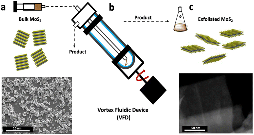 | ||
| Fig. 1 Schematic of the experimental procedure for VFD exfoliating MoS2. (a) Bulk MoS2 dispersed in a 1:1 mixture of ethanol/water with its SEM image before processing. (b) The device operating under continuous flow (rotational speed 8k rpm), MoS2 concentration 5 mg mL−1, at a flow rate 0.45 mL min−1 and tilt angle 45°. (c) STEM image of exfoliated MoS2 nanosheets after VFD processing. | ||
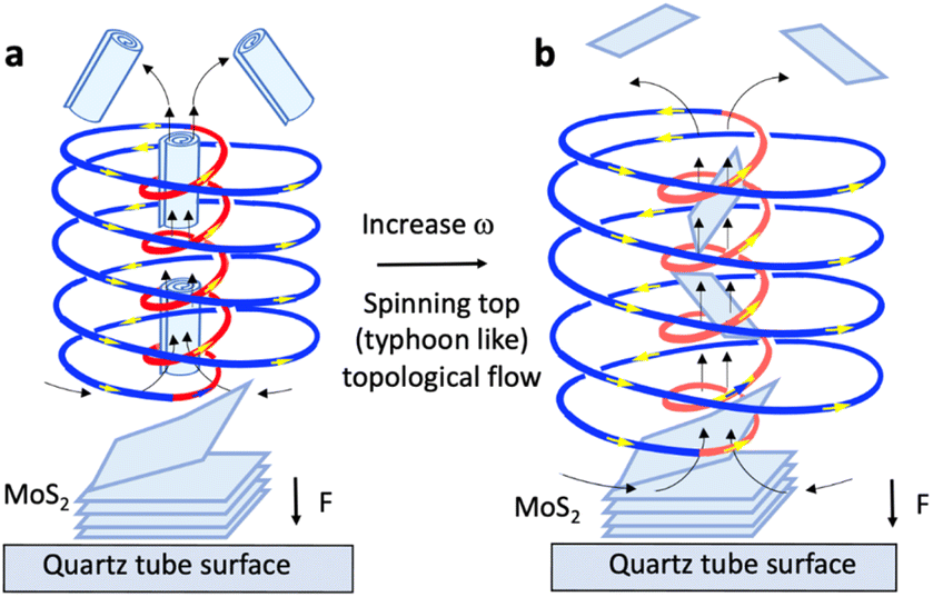 | ||
| Fig. 2 Proposed mechanism of exfoliation of MoS2 controlled by the spinning top (ST) (typhoon like) Coriolis force from the base of the VFD tube, with lateral forces on the surface of the particles and uplift within the core of the ST.12,13 (a) Exfoliation with scrolling at 4k rpm (low speed) arising from inner ST compression on the exfoliated sheets as they are drawn into the ST. (b) ST topological fluid flow exfoliation on the surface of MoS2 particles at 8k rpm (high speed) with the 2D sheets drawn into the core of the larger inner and outer diameter ST without compression. | ||
We established the optimum conditions for exclusively exfoliating MoS2 (i.e. no scroll formation) as follows: as received bulk MoS2 powder was dispersed in a mixture of ethanol and water in a volume ratio of 1:1, at a concentration 5 mg mL−1. Black solutions of dispersed MoS2 were sonicated for 30 min and then injected into the base of the VFD tube rotating at 8k rpm and tilted at 45°, with the system operating at room temperature and the flow rate set at 0.45 mL min−1, noting that this flow rate is optimal for a number of continuous flow processes in the device.16,17 The choice of solvent in the present study for exfoliating MoS2 in forming thin sheets in high yield was critical. Different solvents were explored, at the optimised rotational speed herein (8k rpm), including NMP, DMF and ethanol, with no exfoliation evident, as shown in Fig. S2.† In addition, the concentration of MoS2 was varied, using 2, 5 and 10 mg mL−1, as detailed in Fig. S3,† with exfoliation of 2D sheets at 5 mg mL−1 being deemed optimal.
At high rotational speed, the diameter of the inner flow of the ST is too large to compress the exfoliated sheets into scrolls, Fig. 2a, i.e. the high shear ST topological fluid flow striking the surface of the MoS2 provides the lateral force for exfoliating the material, Fig. 2b, with the 2D sheets able to pass through the larger inner diameter of the ST relative to that at lower rotational speed. We note that the mechanical energy bearing down on the surface of the tube can melt bismuth particles (mp 271.4 °C) for the VFD operating at room temperature, with the molten metal flowing up through the spinning top where it solidifies.13 Thus, the mechanical energy is creating localised heating as well as lateral shear on the layers of MoS2 at the liquid interface with MoS2 particles themselves centrifugally held against the surface of the tube. Exposure to such forcing conditions collectively facilitates the exfoliation, although contact electrification may also be involved.17–19 At high rotational speeds the ST is several microns in diameter and any exfoliated sheets drawn into the uplifting inner part of the spinning top, Fig. 2b, are not confined in space to create scrolls, Fig. 2a. In this context, the optimal conditions for creating MoS2 scrolls is at low rotational speed, 4k rpm, where the outside diameter of the maximum shear stress bearing down on the tube surface ST is smaller than that at higher rotational speeds. The small inner up flow of the ST is responsible for the formation of scrolls, and this occurs in a 1:1:1 mixture of water, ethanol and DMF.15 Exfoliation in the VFD has previously been reported for other 2D materials, notably of graphene from graphite, hexagonal boron nitride,20,21 and phosphorene,22 albeit without an understanding of the mechanism of their formation. The findings herein now provide an understanding of the mechanism of exfoliating 2D MoS2 without spontaneous formation of scrolls, potentially as a general model for exfoliating 2D materials in the VFD. Theoretical studies on exfoliating graphene from graphite established that once scrolling of a graphene sheet passing the edge of the sheet contacting itself, then scrolling becomes energetically favourable.23 Presumably this also applies to the conversion of MoS2 sheets into scrolls.
The exfoliated MoS2 nanosheets were characterized using SEM, TEM, STEM and AFM, XRD and XPS. Fig. 3a presents SEM image at low magnification of exfoliated MoS2. The initial concentration of the bulk materials was 5 mg mL−1, and after processing in the VFD, the final concentration of exfoliated nanosheets was found to be 4.9 mg mL−1 thus giving a high yield of ∼73%, as can be observed from SEM in using a continuous flow process. TEM was used to further investigate the detailed structure of MoS2 nanosheets. Fig. 3b and c shows TEM and HRTEM images of the same material, establishing that the exfoliated nanosheets are extremely thin, being transparent in the SEM, and overlying on each other. HRTEM was used to gain more insight into the structure of the exfoliated MoS2 nanosheets formed in the VFD, as shown in Fig. 3c, establishing that the exfoliated MoS2 has a d-spacing of 0.27 nm. This was directly measured from the HRTEM image and is consistent with d spacing of hexagonal MoS2 (100) planes.24,25Fig. 3d–f displays STEM images along with the elemental mapping of the exfoliated MoS2 nanosheets. The HAADF image in Fig. 3d establishes that the exfoliated MoS2 is very thin. In addition, the elemental mapping of the exfoliated MoS2 nanosheets established the presence of Mo and S throughout the exfoliated layer, Fig. 3e and f. Atomic force microscopy (AFM) was used to investigate the thickness and the lateral size of the exfoliated MoS2 nanosheets. Fig. 4a and b shows the topography image of the exfoliated MoS2 nanosheets associated with its height profile, with the thickness distributions and lateral size of the exfoliated sheets being ∼2 nm and 700 nm respectively, Fig. 4c and d, which is indicative of the formation of monolayer and few layer sheets of MoS2.26,27 Changing the size of the particles of the as received MoS2 had minimal impact on the exfoliation process, Fig. S5.†
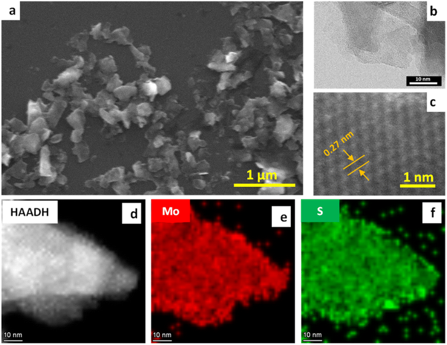 | ||
| Fig. 3 SEM image (a), TEM and HRTEM images (b and c), STEM images (d–f) with elemental mapping, using a VFD, under continuous flow at the optimised conditions, using a 1:1 mixture of ethanol/water, under continuous flow conditions at a flow rate of 0.45 mL min−1 and rotational speed 8k rpm. | ||
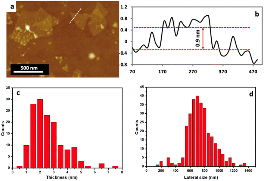 | ||
| Fig. 4 (a and b) AFM image with its height profile of MoS2 (c) layer thickness and (d) lateral size of exfoliated nanosheets synthesized using a VFD, under continuous flow at the optimised conditions. | ||
Raman spectroscopy has been used to investigate structural characteristics of the exfoliated MoS2 nanosheets obtained using VFD processing compared with that of the bulk material. The typical Raman spectra for MoS2 materials shows two characteristic peaks, Fig. S6d,† the A1g and E2g modes, corresponding to the out-of-plane vibration of sulfur atoms and the in-plane vibration of Mo and sulfur atoms.28,29Fig. 5a shows the characteristic Raman spectrum of exfoliated MoS2, having a blue shift near 382 cm−1 corresponding to the E2g, and 407 cm−1 corresponding to the A1g active modes, which is consistent with the presence of exfoliated MoS2 nanosheets. Furthermore, the peak shift indicates a decrease in the number of layers of MoS2.30,31
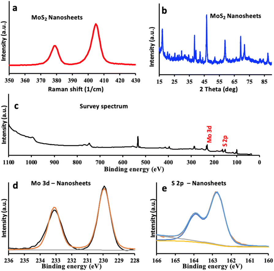 | ||
| Fig. 5 (a) Raman spectra and (b) XRD patterns (c) survey XPS, (d and e) high-resolution spectra of Mo 3d and S 2p, for exfoliated MoS2 nanosheets generated in the VFD under optimal processing conditions. | ||
X-ray powder diffraction (XRD) of the exfoliated material confirmed the phase of MoS2, Fig. S6e,† with 2θ peaks at 14.4, 29.2, 32.6, 33.6, 36.0, 39.7, 44.7, 50.0, 58.5, 60.2, 72.2, 73.8 and 88.3° assigned to the (002), (004), (100), (101), (102), (103), (006), (105), (110), (008), (108), (203) and (118) planes of MoS2, respectively.32,33 After exfoliation using the VFD, all peaks for molybdenite are present, Fig. 5b, however, the intensity of the (002) peak has decreased indicting that the exfoliated nanosheets are consistently very thin, down to a few layers.34,35
XPS was used for verifying the chemical composition of the bulk and exfoliated MoS2. Fig. 5c–e displays XPS survey spectrum and high-resolution scan for Mo 3d for both materials.36 The XPS spectra of Mo 3d, for bulk MoS2, Fig. S6b,† has binding energies at ∼233 eV and ∼229 eV which correspond to Mo 3d3/2 and Mo 3d5/2 respectively.37 After exfoliation to nanosheets, both Mo 3d3/2 and Mo 3d5/2 peaks are observed with the same positions at ∼233 eV and ∼229 eV, Fig. 5d. These peaks can be attributed to the 2H phase of MoS2. Fig. S6c† shows the high-resolution S 2p spectrum of both materials, for bulk MoS2, the S 2p peaks are located at low binding energies of ∼162.2 eV corresponding to that for Mo–S bonds.36 After exfoliation using the VFD, the S 2p3/2 peak has similar pattern with no shift, Fig. 5e, which can also confirm that the exfoliated MoS2 is resulting from the 2H phase and remain unoxidized.38
In summary, we have successfully employed the vortex fluidic device operating under ambient conditions and continuous flow processing to exfoliate MoS2. A significant benefit of this synthetic method is the potential for scaling up of production of the material while ensuring that the processing has environmentally sustainable credentials. In this method, 2D MoS2 nanosheets are generated by the high shear associated with the spinning top topological fluid flow in the thin film in the VFD, impacting on the surface of the rapidly rotating tube. Also of note is that solutions of exfoliated MoS2 prepared in the VFD are colloidally stable over at least 3 months, Fig. S8,† and that the VFD is a relatively energy efficient processing device, as supported in the ESI file.†
Author contributions
T. M. D. A. and C. L. R. designed the experiments, T. M. D. A. performed the experiments and carried out all SEM, TEM, HRTEM, XRD, Raman and XPS. T. M. D. A. and C. L. R. wrote the paper. All the authors approved the manuscript.Conflicts of interest
There are no conflicts to declare.Acknowledgements
The authors also thank Australian Research Council (DP200101105), The Government of South Australia, and AMF for support of this work. T. M. D. A. would like to thank Taibah University (Ministry of Education, Saudi Arabia) for help and support. TEM and HRTEM measurements were undertaken at Adelaide Microscopy, the Centre for Advanced Microscopy and Microanalysis. T. M. D. A. thanks Dr Ashley Slattery from Adelaide Microscopy for assistance with TEM and HRTEM imaging.Notes and references
- A. Giri, G. Park and U. Jeong, Chem. Rev., 2023, 123, 3329–3442 CrossRef CAS PubMed.
- X. Zhu, Z. Su, C. Wu, H. Cong, X. Ai, H. Yang and J. Qian, Nano Lett., 2022, 22, 2956–2963 CrossRef CAS PubMed.
- R. Yang, Y. Fan, L. Mei, H. S. Shin, D. Voiry, Q. Lu, J. Li and Z. Zeng, Nat. Synth., 2023, 2, 101–118 CrossRef.
- G. H. Han, D. L. Duong, D. H. Keum, S. J. Yun and Y. H. Lee, Chem. Rev., 2018, 118, 6297–6336 CrossRef CAS PubMed.
- L. Zheng, X. Wang, H. Jiang, M. Xu, W. Huang and Z. Liu, Nano Res., 2022, 1–20 Search PubMed.
- S. Bellani, A. Bartolotta, A. Agresti, G. Calogero, G. Grancini, A. Di Carlo, E. Kymakis and F. Bonaccorso, Chem. Soc. Rev., 2021, 50, 11870–11965 RSC.
- V. Kaushik, S. Wu, H. Jang, J. Kang, K. Kim and J. W. Suk, Nanomaterials, 2018, 8, 587 CrossRef PubMed.
- J. Zhou, Z. Lin, H. Ren, X. Duan, I. Shakir, Y. Huang and X. Duan, Adv. Mater., 2021, 33, 2004557 CrossRef CAS PubMed.
- Y. Zhao, Y. Yan and J.-M. Lee, Nanoscale, 2022, 14, 1076–1095 Search PubMed.
- E. Varrla, C. Backes, K. R. Paton, A. Harvey, Z. Gholamvand, J. McCauley and J. N. Coleman, Chem. Mater., 2015, 27, 1129–1139 CrossRef CAS.
- X. Yin, Y. Li, W. Wu, G. Chu, Y. Luo and H. Meng, Ind. Eng. Chem. Res., 2017, 56, 4736–4742 CrossRef CAS.
- H. Yuan, X. Liu, L. Ma, P. Gong, Z. Yang, H. Wang, J. Wang and S. Yang, RSC Adv., 2016, 6, 82763–82773 RSC.
- T. Alharbi, M. Jellicoe, X. Luo, K. Vimalanathan, I. K. Alsulami, B. S. A. Harbie, A. Igder, F. A. Alrashaidi, X. Chen and K. Stubbs, Nanoscale Adv., 2021, 3, 3064–3075 RSC.
- M. Jellicoe, A. Igder, C. Chuah, D. B. Jones, X. Luo, K. A. Stubbs, E. M. Crawley, S. J. Pye, N. Joseph and K. Vimalananthan, Chem. Sci., 2022, 13, 3375–3385 RSC.
- T. M. Alharbi, S. Elmas, A. S. Alotabi, M. R. Andersson and C. L. Raston, ACS Sustainable Chem. Eng., 2022, 10, 9325–9333 CrossRef CAS.
- T. Alharbi, K. Vimalanathan, I. Alsulami and C. L. Raston, Nanoscale, 2019, 11, 21394–21403 RSC.
- T. M. Alharbi, Q. Li and C. L. Raston, ACS Sustainable Chem. Eng., 2021, 9, 16044–16051 CrossRef CAS.
- S. Lin, X. Chen and Z. L. Wang, Chem. Rev., 2021, 122, 5209–5232 CrossRef PubMed.
- L. Chen, Q. Shi, Y. Sun, T. Nguyen, C. Lee and S. Soh, Adv. Mater., 2018, 30, 1802405 CrossRef PubMed.
- X. Chen, J. F. Dobson and C. L. Raston, Chem. Commun., 2012, 48, 3703–3705 RSC.
- A. H. M. Al-Antaki, X. Luo, T. M. Alharbi, D. P. Harvey, S. Pye, J. Zou, W. Lawrance and C. L. Raston, RSC Adv., 2019, 9, 22074–22079 RSC.
- M. Batmunkh, K. Vimalanathan, C. Wu, A. S. Bati, L. Yu, S. A. Tawfik, M. J. Ford, T. J. Macdonald, C. L. Raston and S. Priya, Small Methods, 2019, 3, 1800521 CrossRef.
- X. Chen, R. A. Boulos, J. F. Dobson and C. L. Raston, Nanoscale, 2013, 5, 498–502 RSC.
- B. Adilbekova, Y. Lin, E. Yengel, H. Faber, G. Harrison, Y. Firdaus, A. El-Labban, D. H. Anjum, V. Tung and T. D. Anthopoulos, J. Mater. Chem. C, 2020, 8, 5259–5264 RSC.
- G. Gao, C. Chen, X. Xie, Y. Su, S. Kang, G. Zhu, D. Gao, A. Trampert and L. Cai, Mater. Res. Lett., 2017, 5, 267–275 CrossRef CAS.
- G. Eda, H. Yamaguchi, D. Voiry, T. Fujita, M. Chen and M. Chhowalla, Nano Lett., 2011, 11, 5111–5116 CrossRef CAS PubMed.
- Z. Yin, H. Li, H. Li, L. Jiang, Y. Shi, Y. Sun, G. Lu, Q. Zhang, X. Chen and H. Zhang, ACS Nano, 2011, 6, 74–80 CrossRef PubMed.
- W. Han, Y. Xia, D. Yang and A. Dong, Chem. Commun., 2021, 57, 4400–4403 RSC.
- X. Wu, Y. Li, L. Chen, J. Zhao, B. Wu and Z.-B. Zhang, Chem. Commun., 2020, 56, 2035–2038 RSC.
- Z. Mohammadpour, S. H. Abdollahi and A. Safavi, ACS Appl. Energy Mater., 2018, 1, 5896–5906 CrossRef CAS.
- H. Li, Q. Zhang, C. C. R. Yap, B. K. Tay, T. H. T. Edwin, A. Olivier and D. Baillargeat, Adv. Funct. Mater., 2012, 22, 1385–1390 CrossRef CAS.
- V. Štengl and J. Henych, Nanoscale, 2013, 5, 3387–3394 RSC.
- Q. Yang, Z. Wang, L. Dong, W. Zhao, Y. Jin, L. Fang, B. Hu and M. Dong, J. Phys. Chem. C, 2019, 123, 10917–10925 CrossRef CAS.
- Y. Li, X. Yin and W. Wu, Ind. Eng. Chem. Res., 2018, 57, 2838–2846 CrossRef CAS.
- D. Sahoo, B. Kumar, J. Sinha, S. Ghosh, S. S. Roy and B. Kaviraj, Sci. Rep., 2020, 10, 1–12 CrossRef PubMed.
- J. Guo, H. Zhu, Y. Sun, L. Tang and X. Zhang, Electrochim. Acta, 2016, 211, 603–610 CrossRef CAS.
- D. Qi, S. Li, Y. Chen and J. Huang, J. Alloys Compd., 2017, 728, 506–517 CrossRef CAS.
- Q. D. Truong, M. Kempaiah Devaraju, Y. Nakayasu, N. Tamura, Y. Sasaki, T. Tomai and I. Honma, ACS Omega, 2017, 2, 2360–2367 CrossRef CAS PubMed.
Footnote |
| † Electronic supplementary information (ESI) available. See DOI: https://doi.org/10.1039/d3na00880k |
| This journal is © The Royal Society of Chemistry 2023 |