DOI:
10.1039/D3NA00836C
(Paper)
Nanoscale Adv., 2023,
5, 7042-7056
Cobalt-substituted ZnS QDs: a diluted magnetic semiconductor and efficient photocatalyst†
Received
29th September 2023
, Accepted 7th November 2023
First published on 9th November 2023
Abstract
Recently, understanding the origin of induced magnetic characteristics in transition metal atom-doped QDs has been a major focus owing to their potential applications in the area of spintronic devices. A detailed experimental and theoretical investigation was conducted to understand the physical properties of Co-doped ZnS QDs containing different weight percentages of Co atoms [CoxZn1−xS (x = 0.00, 0.03, 0.06, and 0.09)], prepared using chemical co-precipitation techniques. X-ray diffraction studies proved that all the prepared QDs formed an extremely pure cubic zinc blende crystallographic phase free of contaminants. The validation of the quantum dot nature of all the samples was provided by the HRTEM images, BET studies, and blue shift in the absorption spectra. Both the obtained FTIR and PL spectra at room temperature also confirmed the phase purity of the prepared QDs. The observed weak ferromagnetic behavior of the doped samples was due to the presence of p–d hybridization between the 3d levels of Co2+ ions and 3p levels of S2− ions of the host ZnS QDs. Hysteresis loops that were obtained at room temperature validated this weak ferromagnetic nature. These obtained results were also supported theoretically using DFT calculations. FDTD simulations provided a detailed explanation for the observed blue shift in the absorption spectra originating from the quantum confinement effect of doped and undoped ZnS QDs. The dielectric properties of all the samples were examined properly, and it was also found that the grain boundaries contributed effectively to providing the dielectric response. The doped ZnS sample containing more Co dopants at low frequencies showed a progressive rise in polarisation loss. In addition, Co-doped ZnS QDs are efficient photocatalysts. A pH-dependent photodegradation test of ciprofloxacin (CIP) antibiotic was conducted using 9% Co-doped ZnS QDs. It was observed that 9% Co-doped ZnS nanocatalysts has sufficient capability to degrade CIP to around 94.7% in a solution of pH 10 within one hour. Therefore, besides showing photocatalytic effects, Co-doped ZnS QDs act as ideal dilute magnetic semiconductors (DMSs) and will undoubtedly become excellent candidates for the microelectronics industry because of their special ability to exhibit spin-dependent magneto-electro-optical properties that find use in spin-polarized light-emitting diodes, solid-state lasers, and spin-transistor devices.
1. Introduction
Antibiotics are widely used to treat a variety of infections, saving millions of lives since their discovery. In India, an increasing number of antibiotics are used now-a-days to improve the health of a large population. The abuse and untreated discharge of several antibiotics result in drug resistance and pose a serious threat to both the human health and the environment.1–4 Antibiotic contamination is now a crucial environmental issue globally. One of the documented antibiotic pollutants discovered in aquatic environments is ciprofloxacin (CIP). The synthetic CIP as a third-generation quinolone antibiotic exhibits a wide range of applications in pharmacological and biological fields. An efficient method to remove CIP and other antibiotics from wastewater is long overdue. Antibiotic contamination in wastewater and the environment can be reduced effectively via photocatalytic degradation when appropriate nanocatalysts are used.4–8 In this direction, nanosized II–VI semiconductors have attracted much attention from researchers due to their unique physical characteristics and adequate optical bandgap, which endow them with effective photocatalytic activities. Among all other available semiconductors, zinc sulphide (ZnS) is the most interesting II–VI semiconductor owing to its stable cubic zinc blende crystal structure. It can be used as an effective photocatalyst by varying the bandgap via incorporating suitable dopants within the percolation limit.9–11 In addition to its photocatalytic activities, the ZnS quantum dots serve as an effective host for diluted magnetic semiconductors (DMSs), and by substituting appropriate magnetic ions, magnetic properties can be introduced within it to explore the spintronics domain.12,13
A significant amount of research has been conducted worldwide in recent years to understand the origin of room-temperature weak ferromagnetism in DMSs that contain transition metal dopants, because of their anticipated spintronic device applications.12 The doped DMS QDs are also the best templates for examining the magnetic behavior at the fundamental level along with the myriad applications for modern technologies. However, the causes of weak ferromagnetism in doped DMS systems observed at room temperature are still unclear and a subject of debate. Various novel properties such as half metallicity, strong thermal stability, and excellent magneto-optical, dielectric, and electrical properties of transition metal ion-doped DMS nanomaterials make them efficient for use in spintronic devices.14–16 Research on the sources of weak ferromagnetism in doped II–VI semiconductors and the methods for achieving ferromagnetism at room temperature has significantly increased in current years.12
ZnS nanocrystals are also promising for a wide range of optoelectronic applications including LEDs, sensors, solar cells, and lasers. The transition metal-doped ZnS nanocrystal has gained tremendous interest as a ‘dilute magnetic semiconductor’ (DMS) in spintronic devices. ZnS is also an environment-friendly wide-bandgap semiconducting material having a direct optical bandgap of 3.66 eV at room temperature. Subject to ZnS quantum dots (QDs), the bandgap was found to increase due to the strong quantum confinement effect when the dimension of nanocrystals attains well below the Bohr exciton radius (2.6 nm).12–15 A notable blue shift in the absorption spectra is the signature of confinement effect. Generally, a dilute magnetic semiconductor (DMS) exhibits typical semiconductor behavior, yet its magnetization can be induced through various factors including exchange interactions mediated by free carriers or more exotic mechanisms like F-center ferromagnetism coupling. By incorporating transition metal ions such as Fe, Co, and Ni, which exhibit magnetic behavior at room temperature, magnetic properties can be imparted to the host DMS system.12,16 It has been reported that the physical prosperities of ZnS change with the change in external pressure13 and transition metal dopant concentration.14 In this study, we chose Co ions as dopants for the host ZnS QDs to induce magnetic characteristics and also to explore the photodegradation properties. It is because of the fact that the Co ion displays a high Curie temperature (1388 K) and shows ferromagnetism at room temperature. It is also comparable in size with Zn ions, thereby easy to replace the Zn ions with Co ions in the host ZnS structure without having secondary phases. The doping of magnetic Co ions in ZnS QDs can drastically alter the structural, optical, dielectric and magnetic properties in addition to their photocatalytic properties.17,18
In recent years, several research groups across the globe have tried to explain the origin of ferromagnetism and half metallic feature of transition metal ion-doped ZnS QDs theoretically via electronic structure calculations. In this regard, both the classical and quantum physics simulations are considered to be the most efficient methods for investigating the various properties of nanostructured materials. In general, the density functional theory (DFT) as well as the finite difference time domain (FDTD) method has been used to determine the structural, electronic as well as optical properties of doped and undoped QDs.13 Therefore, in our present study, we used DFT to investigate the impact of Co doping on the lattice structure of ZnS QDs as well as how doping affects its density of states (DOS) spectrum and sp–d, p–d hybridizations. In addition, the FDTD method was used to see the change in the optical UV-visible absorption spectrum of doped and undoped QDs. We provide a theoretical explanation for the possible cause of the observed weak ferromagnetism in Co-substituted ZnS QDs via hybridization.13–16
Several methods are readily available for the easy synthesis of transition metal ion-doped ZnS QDs. We chose to adopt the wet chemical co-precipitation method to prepare pure and doped ZnS QDs among all these available preparation techniques, since it offers the best shape and size uniformity. This technique makes the synthesis of QDs simpler and also less expensive. Various parameters such as size, shape, surface morphology, type of dopants, and synthesis methods have a significant impact on the physical properties of QDs, allowing for efficient tuning of physical properties.12,13,16,19
This work emphasizes both the theoretical and experimental investigations on the induced weak ferromagnetism of Co-doped ZnS QDs at room temperature along with photodegradation of the CIP antibiotic, prepared via a wet chemical co-precipitation route. Co-doped ZnS QDs were found to be efficient to degrade antibiotics. Clear weak ferromagnetic signature in all the doped ZnS QDs was recorded at 300 K. In addition, by introducing magnetic properties in diamagnetic ZnS QDs, the effects of Co ion doping on the structural, optical and dielectric properties of ZnS QDs have also been examined thoroughly. Proper correlations among those physical properties were established in this study.
2. Experimental details
2.1. Preparation of pure ZnS QDs and cobalt-doped ZnS QDs
The standard wet chemical co-precipitation method was utilized to synthesize entire pure and Co-doped ZnS QDs having the chemical composition CoxZn1−xS (x = 0.00, 0.03, 0.06 and 0.09).12–16 All the prepared samples were in powder form and indexed as Co-00 (ZnS), Co-03 (ZnS), Co-06 (ZnS), and Co-09 (ZnS) respectively, as per the increasing Co content in ZnS QDs. Various physical characterizations and photodegradation activities of these prepared powder samples were further conducted. The synthesis method of these samples is discussed in detail in the ESI section.†
2.2. Dielectric property measurement
The dielectric properties and the ac conductivity of all the prepared QD samples were determined using an LCR meter (HIOKI). All the dielectric properties were measured in the frequency range of 4 Hz–8 MHz at 300 K. For the dielectric measurement, we prepared a thin circular pellet of diameter 13 mm using powder samples.20 Silver paste was applied on both sides of the pellet to make contact. Further, all the dielectric parameters of QDs were measured using all these prepared pellets.
2.3. QD-based photocatalytic degradation of CIP
Ciprofloxacin (CIP) is a fluoroquinolone synthetic antibiotic used to cure multiple bacterial infections. When released into the environment untreated, CIP can also act as a pollutant.1–8 The physicochemical characteristics of CIP are presented in Table S1 (ESI section).† Co-doped ZnS QDs were employed in the photocatalytic experiments to degrade CIP in water solutions. For photodegradation, a stock solution of CIP in water was made. Each drug-containing conical solution was produced through the addition of QDs to the reaction solutions. All the tests were conducted at a steady temperature in a batch reactor. The temperature of the process was held constant at 29 ± 1 °C. During the degradation experiment, a xenon lamp was used as the light source (wavelength range: 400 nm–1000 nm). With steady stirring, an appropriate amount of catalyst (0.01 g L−1 dosage) was dissolved in 100 mL of the CIP solution. Before light illumination, the solution was maintained in the darkness for 45 minutes to achieve adsorption–desorption equilibrium. The light source was then turned on, and that period of time was designated as “time zero” for the study of the photocatalysis reaction. A xenon lamp was used to irradiate the solutions in order to provide energy.2,21–23 Using a syringe, sample aliquots were collected from the solution at predetermined intervals, and the drug concentration was subsequently measured by spectrophotometry after centrifugation. After exposure to radiation for a specific amount of time, the decrease in absorbance (at max = 270 nm) for drug samples showed the rate of degradation and, consequently, the effectiveness of the drug oxidation and photocatalytic effect of QDs. The degradation efficiency in percentage (%) was obtained using the following equation:21–23| |  | (1) |
where C0 is the initial CIP concentration and C is the concentration of CIP solution at a specific time t after the xenon light irradiation. Similarly, both A0 and At denote the initial and final absorbance of the CIP-containing solution obtained at the peak position (λ = 270 nm) of the highest absorbance.
2.4. Characterization techniques
All the physical properties including structural, surface morphology, optical, magnetic and dielectric characteristics of the synthesized pure and doped QDs were investigated thoroughly. Both the DFT and FDTD simulation methods were employed to examine all the samples theoretically. The details of all the applied characterization techniques are attached in the ESI section.†
3. Results and discussion
3.1. XRD pattern analysis
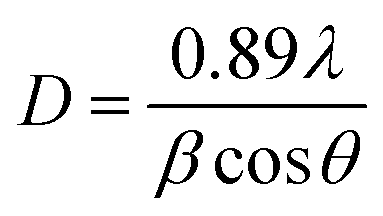
Fig. 1 depicts the XRD diffraction spectra of Zn1−xCoxS (x = 0.00, 0.03, 0.06 and 0.09) QDs containing different concentrations of Co ions, registered at room temperature. The formation of cubic zinc blende crystal structure was verified by the obtained diffracted peaks from the lattice planes having Miller indices (111), (220) and (311) respectively.12 All the obtained diffraction peaks in the XRD diffractograms were noted to match exactly with the ICDD card number 00-005-0566. The crystallographic phase-purity of all the samples was confirmed by the absence of any foreign peaks in the XRD profiles other than the primary peaks of the zinc blende phase.12,13 The broadened peaks showed in the diffractogram served as the confirmation of both the nanocrystalline feature and the nanosize nature of entire synthesized materials. Mainly the three primary parameters, i.e., crystallite size effect, microstrain in the tiny crystal and instrumental effects are mainly responsible for the observed broadening in the XRD peak profiles. A XRD pattern obtained from the bulk LaH6 powder was considered as a reference for both the peak position calibration and removal of instrumental broadening effects.16,21 The diffracted (111) peak having the highest intensity was used to evaluate the mean size of the nanocrystallites. This (111) peak was fitted with the Gaussian curve to calculate the full width at half maxima (FWHM) of the peak. The obtained values of FWHM were further used to determine the mean crystallite size for each sample using Scherrer's formula.13,16 After eliminating the instrumental broadening, the FWHM of the most intense (111) peak was used to calculate the average crystallite size (D) of all the QD samples using Scherrer's formula as follows:16–21| |  | (2) |
where λ is the wavelength (1.5406 Å) of copper Kα X-ray line, θ represents Bragg's diffraction angle and β corresponds to the FWHM of the (111) peak respectively. The calculated values of mean crystallite size were found in the range of 1.1 ± 0.1 nm for all the QD samples, as shown in Table 1. The Bohr excitonic radius for the ZnS nanomaterial is approximately 2.6 nm, which is used to limit the size of an electron–hole pair.13 The calculated values of mean crystallite size as seen from Table 1 for all the doped and undoped samples were found well below the Bohr excitonic radius, causing strong quantum confinement effects.13
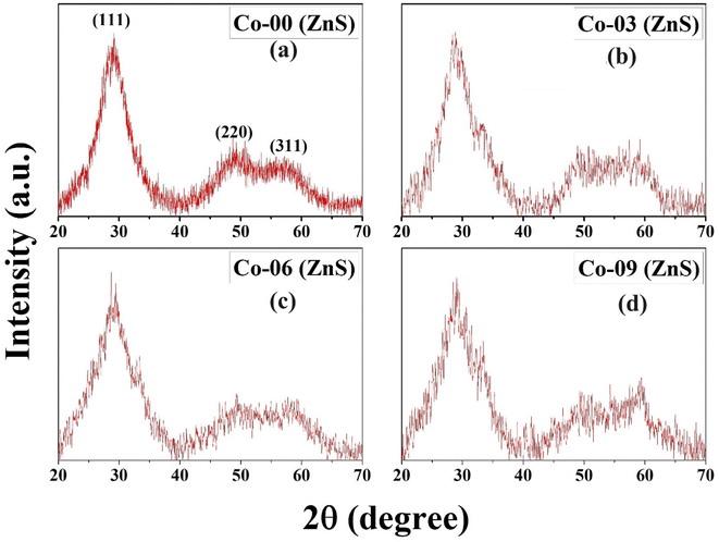 |
| | Fig. 1 Room-temperature P-XRD patterns of (a) Co-00 (ZnS), (b) Co-03 (ZnS), (c) Co-06 (ZnS) and (d) Co-09 (ZnS) QDs. | |
Table 1 Mean crystallite size and lattice parameter of all the samples
| Sample id |
D (nm) |
a (Å) |
| Co-00 (ZnS) |
1.2 |
5.362 |
| Co-03 (ZnS) |
1.1 |
5.351 |
| Co-06 (ZnS) |
1.0 |
5.325 |
| Co-09 (ZnS) |
1.0 |
5.314 |
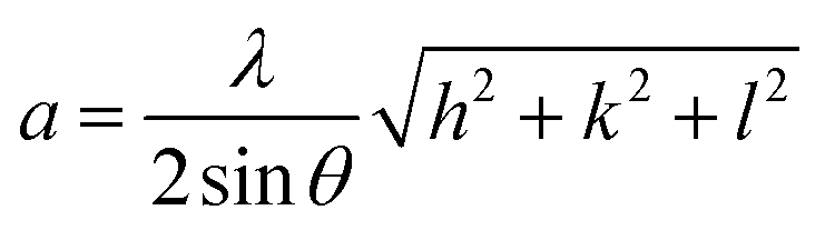
The lattice constant (a) of the unit cell for all the CoxZn1−xS QDs was obtained using the following relation:13,24,25
| |  | (3) |
where
hkl denotes the Miller indices and others are known symbols. The estimated values of lattice constant for all the QD samples are presented in
Table 1. With the increase in Co concentration in ZnS nanocrystals, there was a consistent decrease in lattice constant. This is due to the fact of mismatch in the ionic radii of Co
2+ (0.65 Å) and Zn
2+ (0.74 Å) ions, as the Co
2+ ion is smaller than the Zn
2+ ion, thus substitution of Co
2+ ions in the host ZnS structure lead to a reduction in lattice constant.
18
3.2. HRTEM image analysis
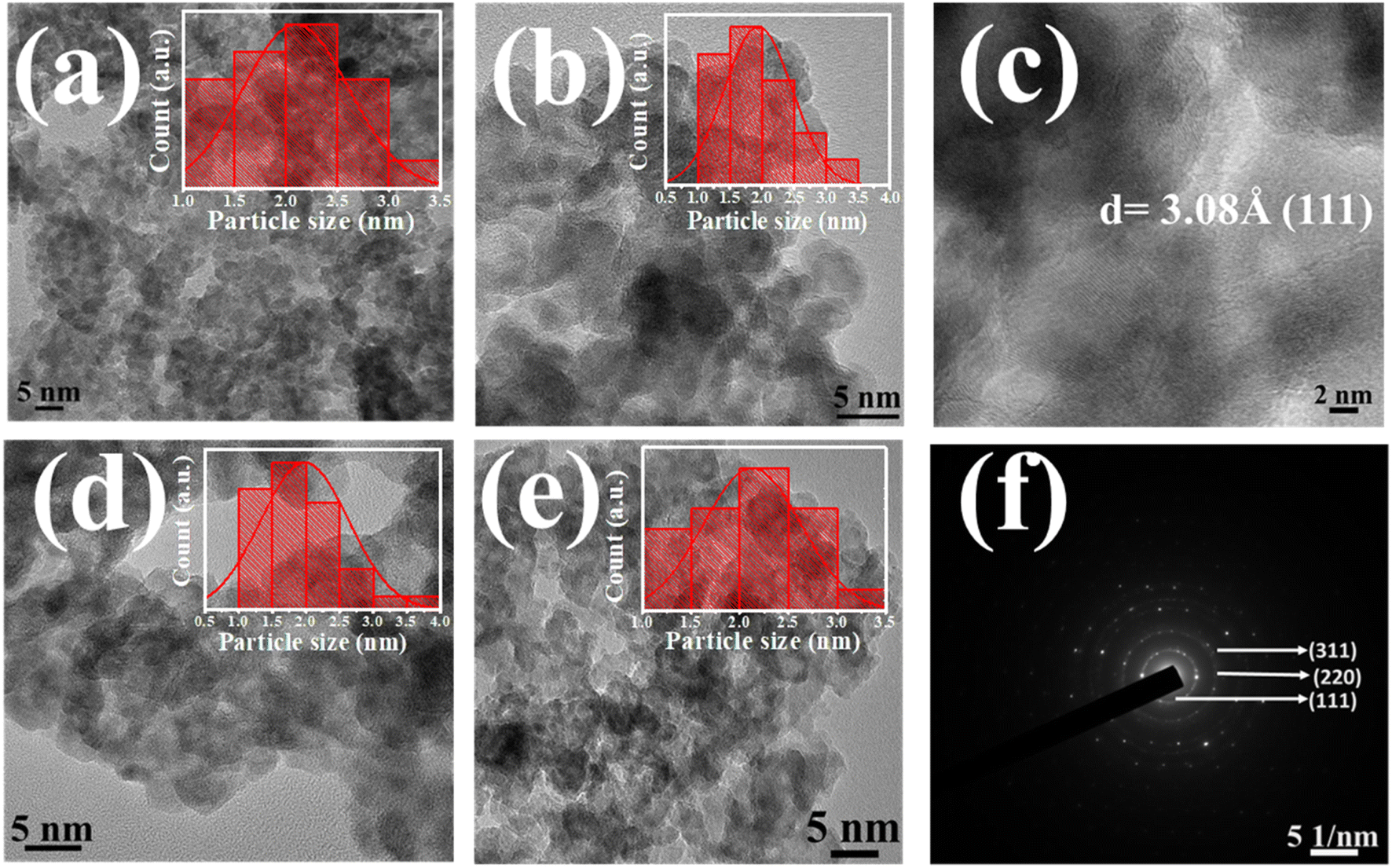
Fig. 2a, b and d, e illustrates the captured HRTEM images of all the pure and doped QDs respectively. The observed significant aggregation among prepared QDs in all HRTEM images might be attributed to both the interparticle interactions and van der Waals interactions. All the micrographs showed that the synthesized QDs were almost spherically shaped. Histograms were drawn to understand both the size distribution and the mean particle size of pure and doped ZnS QDs, which are depicted in the inset of HRTEM images.12,13 A mean particle size of 2.1 ± 0.1 nm was calculated for the Co-00 (ZnS) sample, and it was 2.0 ± 0.1 nm, 1.9 ± 0.1 nm and 2.1 ± 0.1 nm for Co-03 (ZnS), Co-06 (ZnS) and Co-09 (ZnS) samples respectively. All the estimated values of average particle size were found to follow the mean crystallite size and support the evidence of strong quantum confinement of excitons.25 It can also be noted that an exceptional homogeneity in both size and shape was attained as noticed from the micrographs. The interplanar distance for the (111) plane was obtained and that was found to be 3.08 Å, as depicted in Fig. 2c. The selected area electron diffraction (SAED) pattern of Co-03 (ZnS) QDs was also captured and is shown in Fig. 2f. The observed concentric circular rings in the SAED pattern signified the crystalline nature of prepared QDs and were named with their respective Miller indices.16,25 The captured SAED pattern also revealed the fcc-like cubic zinc blende crystal structure of the prepared nanomaterial.21
 |
| | Fig. 2 (a and b) HRTEM images of Co-00 (ZnS) and Co-03 (ZnS) QDs. (c) Interplanar spacing of Co-03 (ZnS). (d and e) HRTEM images of Co-06 (ZnS) and Co-09 (ZnS) QDs. (f) SAED pattern of Co-03 (ZnS) QDs respectively. | |
3.3. UV-vis spectra studies
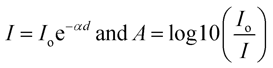
UV-visible absorption spectra are widely used to determine the optical bandgap of semiconducting nanomaterials. Room-temperature absorption spectra of all the pure and doped ZnS QDs were recorded in the band of 100–1000 nm respectively. It is experimentally verified that pristine ZnS is a wide bandgap semiconducting material with a direct bandgap of 3.66 eV at 300 K.13,25 Due to the confinement effect in nanoscale domain, the ZnS QDs show a slightly larger direct optical band gap. The direct optical transition for all the doped and undoped ZnS QDs can be evaluated using the Tauc relation as follows:20where ‘B’ symbolizes an arbitrary constant, ‘Eo’ specifies the energy for direct optical transition of QDs, ‘α’ corresponds to the absorption coefficient, and ‘n’ is an index. The index might have values of 1/2 and 3/2 for direct allowed and direct forbidden optical transitions. The estimation of minimum required energy for direct optical transition at 300 K can be done by plotting a graph of (αhν)2 against photon energy (hν). In this regard, the values of absorption coefficient (α) for all the QDs can be obtained by using these two elementary relationships and recorded absorbance (A) data, as follows:26,27| |  | (5) |
Hence,  where ‘d’ is the thickness of the container. The minimum energy required for direct optical transition, i.e., direct band gap (Eo) for all the samples was estimated using a graph drawn between (αhν)2 and hν, which is known as the Tauc plot and is shown in Fig. S1 (in ESI).† The values of Eo for all the prepared Co-doped and pure ZnS QDs are tabulated in Table S2 (in ESI)† respectively. The obtained values of direct bandgap for both the pristine and doped ZnS QDs were slightly greater than that of the bulk ZnS. It is due to the fact of strong confinement effects.25 A systematic increase in the optical band gap was also noted for the samples having more Co dopants, which clearly indicates a better confinement effect than that of pristine ZnS QDs. It is easily understood by analyzing the absorption spectra of all the QDs that all the samples revealed an opaque nature in the UV region of the electromagnetic spectrum. A significant blue shift in the absorption of EM wave was also observed for a higher Co content of QDs. All of the fabricated QDs are appropriate for use in optical applications due to their exceptional UV band absorption qualities.21,26
3.4. FDTD analysis
Fig. 3a and b represent the geometrical structure of ZnS QDs and Co-doped ZnS QDs respectively. The primary objectives of the simulations are to calculate the absorption cross-section as a function of wavelength for both types of quantum dots. The UV-vis spectroscopy examination is an effective way to explore the impact of doping on the optical characteristics of ZnS QDs. In general, the absorption represents electron excitation from the valence band to the conduction band.28 The simulated absorption spectra of undoped ZnS and Co-doped ZnS QDs in the UV region are shown in Fig. 3c. The absorption peaks of undoped ZnS QDs are found at 354 nm, which is blue-shifted than corresponding to the bulk band gap of the ZnS sample because of the quantum confinement effect. However, the absorption peak of Co-doped ZnS QDs is further shifted to shorter wavelengths than those of undoped ZnS. This shifting arises due to the increase in band-gap energy caused by the doping of Co in the ZnS lattice structure.
 |
| | Fig. 3 (a and b) Geometrical structure of ZnS QDs and Co-doped ZnS QDs. (c) Simulated absorption spectra of undoped ZnS and Co-doped ZnS QDs. | |
3.5. FTIR spectra studies
FTIR spectroscopy is typically used to identify the synthesized compounds, various functional groups and associated chemical linkages present in the samples. It can be utilized as a fingerprint technique to recognize the materials by scanning them with the infrared light region of EM spectra and recording the corresponding chemical characteristics.21 Fig. S3 (in ESI)† shows the FTIR spectra of undoped, and 3%, 6% and 9% Co-doped ZnS QDs respectively, registered at 300 K within the wave number range of 400 cm−1 to 4000 cm−1. The distinctive peaks of ZnS were clearly visible in the collected FTIR spectra. The band appearing between 3000 cm−1 and 4000 cm−1 in the spectra is ascribed to the OH− ion stretching modes trapped inside the crystals.12,13 The produced bands within 1962 cm−1 and 2116 cm−1 are attributed to the C–H stretching vibrations present in the samples. The observed peaks between 1418 cm−1 and 1622 cm−1 correspond to the symmetric and asymmetric stretching vibrations of C![[double bond, length as m-dash]](https://www.rsc.org/images/entities/char_e001.gif) O bonds. All the characteristic FTIR active peaks of the ZnS material were found between 600 cm−1 and 1300 cm−1 for entire samples. The peak detected near 925 cm−1 for all the QD samples is assigned to the symmetric stretching vibration of Zn–S bonds. With doping of Co ions in host QDs, a slight change in the peak was observed.12,13 Normally, the three parameters, namely, reduced mass, the chemical bond's spring constant, and the length of the bond have a significant impact on deciding the characteristic vibration frequencies of all the prepared QDs.
O bonds. All the characteristic FTIR active peaks of the ZnS material were found between 600 cm−1 and 1300 cm−1 for entire samples. The peak detected near 925 cm−1 for all the QD samples is assigned to the symmetric stretching vibration of Zn–S bonds. With doping of Co ions in host QDs, a slight change in the peak was observed.12,13 Normally, the three parameters, namely, reduced mass, the chemical bond's spring constant, and the length of the bond have a significant impact on deciding the characteristic vibration frequencies of all the prepared QDs.
3.6. Photoluminescence spectra studies
Photoluminescence spectra of ZnS QDs and Co-doped ZnS QDs were measured at room temperature and are illustrated in Fig. S4 (in ESI).† Both the ZnS QDs and Co-doped ZnS QDs were excited at 330 nm, which exhibited two distinct emission peaks at 370 nm and 445 nm. The emission peak at 370 nm is attributed to sulfur ions within the quantum dot. The emission peak at 445 nm is attributed to the presence of cobalt ions within the quantum dots, which is characteristic of cobalt ions. Cobalt ions act as sensitizing agents, enhancing the radiative recombination processes in the quantum dots.12,28,29 As the doping concentration of cobalt increases, the number of luminescence centers (cobalt ions) also increases, leading to a substantial increase in the PL intensity of the blue emission at 445 nm.30,31 The observation from the PL emission spectra suggests that cobalt ions were successfully incorporated into the zinc sulfide lattice, as expected. This observation is supported by the results of powder X-ray diffraction (XRD) obtained at room temperature. Interestingly, there was no concentration quenching effect observed up to 9% of cobalt doping concentration. This is in contrast to previous reports, where a decay occurred in photoluminescence intensity at a lower cobalt concentration of 5%.32 The lack of concentration quenching indicates that cobalt ions effectively replaced zinc ions within the lattice, even at a higher doping concentration of 9%. The findings suggest that cobalt doping in ZnS quantum dots enhances the luminescence intensity, and this enhancement is attributed to the successful incorporation of Co ions into the ZnS lattice, where they serve as luminescent centers, rather than remaining on the surface or in interstitial positions.
3.7. Analysis of magnetic properties
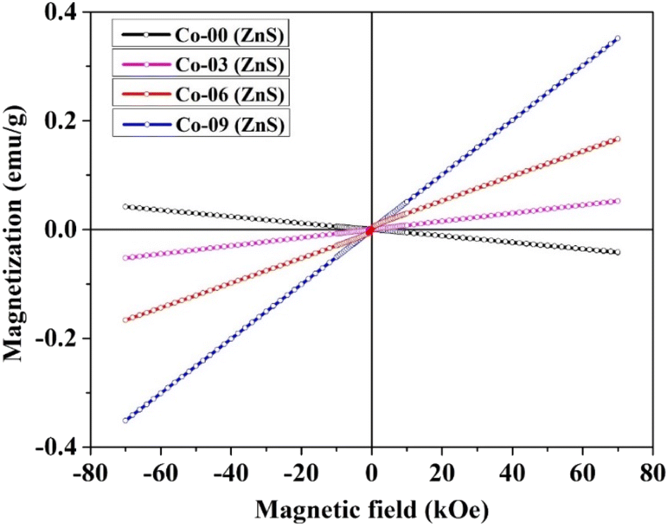
Room-temperature hysteresis loops of the synthesized Co-doped ZnS QDs with a general composition of Zn1−xCoxS (x = 0.00, 0.03, 0.06 and 0.09) were collected, and are depicted in Fig. 4. Pristine ZnS QDs showed completely diamagnetic behavior at room temperature. Weak ferromagnetic properties were introduced in the diamagnetic ZnS QDs by incorporating Co ions within the percolation limit. The appearance of weak ferromagnetic behavior at room temperature in pure ZnS nanocrystals doped with 3d transition metal magnetic (Co2+) ions is attributed to the p–d exchange interactions.25 Two important parameters, namely, the bond length and bond angle in between 3d transition metal Co2+ cations and S2− anions decide the p–d hybridization in the host ZnS crystal structure. The existence of a crystalline electric field or crystal field inside the ZnS crystal structure causes the degenerate 3d ground state of the Co ion in a tetrahedral coordinated environment to split into t2g levels and eg levels.12,16 For tetrahedral sites, the energy of t2g level is greater than the eg level; therefore, the eg levels form the ground state. The coulombic interactions between electrons in the eg levels in the host ZnS matrix are higher than the crystal field splitting energy required to produce both the t2g and eg levels, favouring the high spin configuration. Strong p–d hybridization is produced in the system by the fact that the 3p levels of S2− ions that make up the valence band of pure ZnS are energetically equivalent to the 3d levels (t2g and eg) of Co ions. Since cobalt shows a lower electron affinity than that of zinc, the Co3+ oxidation state of cobalt ions is also possible inside the n-type ZnS structure. The presence of p–d hybridization between Co2+ and Co3+ also favours the magnetic exchange interactions mediated by the hopping of electrons between Co2+ and Co3+ ions.16,24 This hopping of electron due to p–d hybridization leads to the formation of weak ferromagnetic coupling. Because of the p–d hybridization between 3d levels of Co ions and the 3p levels of S2− ions of host ZnS, magnetic interactions take place that favour the ferromagnetic coupling of Co ions in the ZnS structure. Due to this phenomenon at room temperature, all of the Co-doped ZnS QDs displayed weak ferromagnetism. Moreover, the presence of inherent vacancies in host ZnS QDs favors the n-type semiconducting nature of the sample. It is reported that the doped ZnS QDs consist of a number of intrinsic defects (Zn-vacancies) that also favour the appearance of high TC ferromagnetism at room temperature. Pure ZnS QDs were doped with ferromagnetic Co cations, which promoted sp–d or p–d hybridization and caused the development of weak ferromagnetism at 300 K.24 Hysteresis loops demonstrated that all of the Co-doped ZnS QDs were weakly ferromagnetic in nature at room temperature. The maximum coercive field (91 Oe) was found in a ZnS QD sample that was doped with 9% Co ions. The effect of varying dopant concentration within the percolation limit on the magnetic properties of the compound is listed in Table S3 (in ESI).† The uncompensated canted surface spins that were ferromagnetically coupled demand more energy to saturate at 300 K. This explains the observation of unsaturated hysteresis loops at room temperature.12,16,33 As the ±70 kOe magnetic field failed to saturate the hysteresis curves, we measured the maximum magnetization (M7T) at 70 kOe for all the samples and listed in Table S3 (in ESI).† It was clearly noticed that the values of M7T increase with the increase in dopant concentration, which is expected.
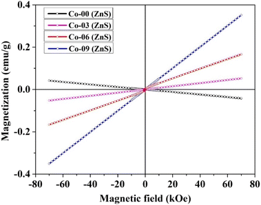 |
| | Fig. 4 Room-temperature hysteresis loops of all the prepared QDs. | |
3.8. DFT study
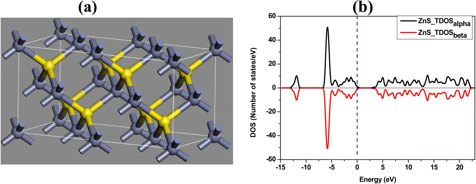
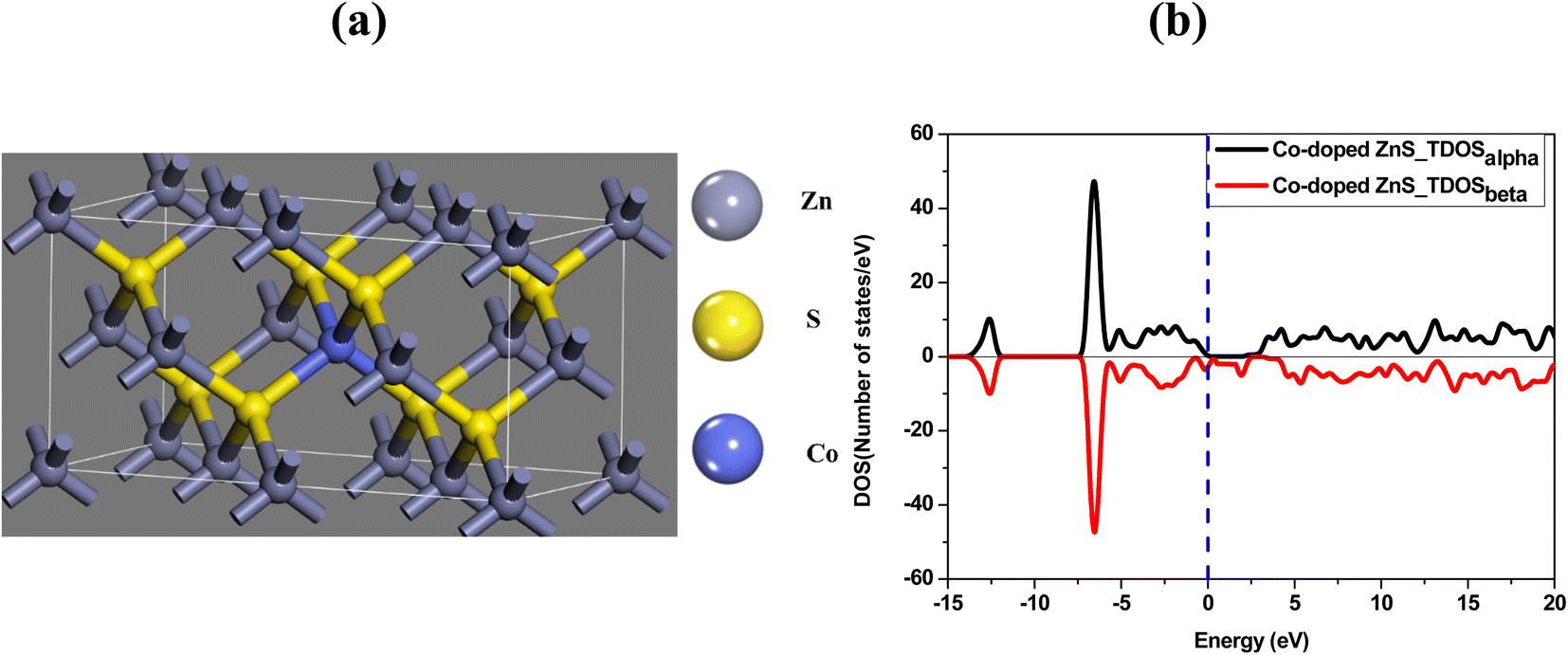
The optimized structure and the total density of states of undoped ZnS are shown in Fig. 5a and b respectively. While plotting the density of states spectrum, both spin-up (alpha) and spin-down (beta) states are considered. Afterwards, one Zn atom is then replaced with a Co atom in the undoped ZnS lattice structure. The Co-doped ZnS is then optimized and all the electronic properties are calculated. Both Fig. 6a and b represent the optimized structure and total density of states of Co-doped ZnS respectively.
 |
| | Fig. 5 (a) Optimized structure of ZnS. (b) Total density of states of the ZnS structure. | |
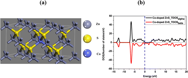 |
| | Fig. 6 (a) Optimized structure of Co-doped ZnS. (b) Total density of states of the Co-doped ZnS structure. | |
The results obtained from the present simulation indicate that after structural optimization, the bond length between the dopant atom (i.e. Co) and the surrounding atoms is found to be 2.29 Å, which is smaller than the bond length of undoped ZnS, which is around 2.34 Å. In this case, the S atom shifts nearer to the Co atom after geometric optimization, which signifies the suppression of the structure of the Co atom.33 The local bonding environment of ZnS is significantly affected by the addition of the Co dopant due to the variation in the covalent radii (1.22 Å, 1.05 Å and 1.26 Å for Zn, S and Co, respectively)34 and electro-negativities (1.65, 2.58 and 1.88 for Zn, S and Co, respectively).35,36
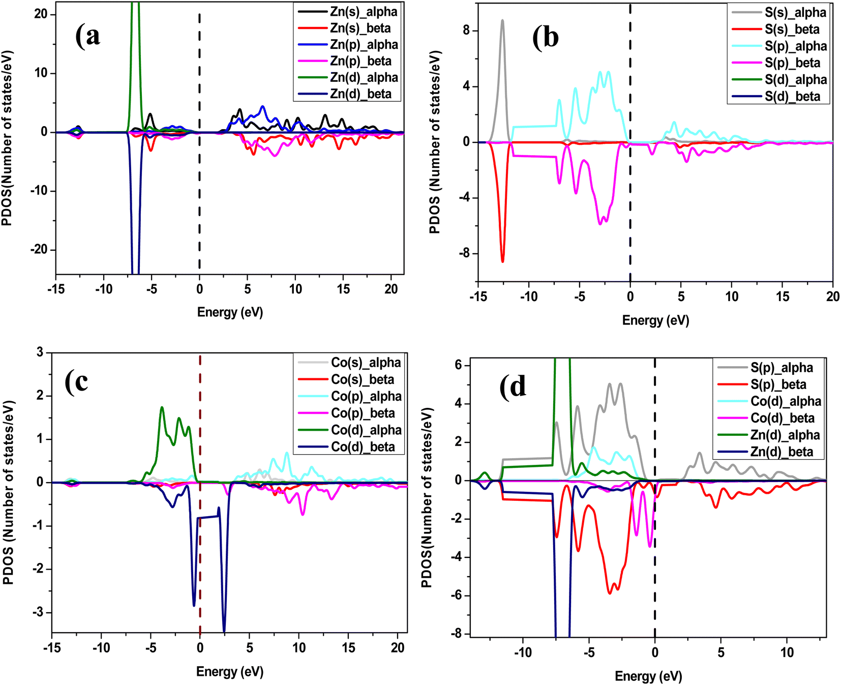
To examine the half-metallic property of the Co doped system, we plotted the partial density of spin-up (alpha) and spin-down (beta) states with a dotted vertical line that represents the Fermi level. For undoped ZnS, the top of the valence band is developed by the S (p) states as well as Zn (d) states, whereas above the Fermi level, the bottom of the conduction band is created by Zn (s) states. The partial density of states of Zn in Co-doped ZnS is shown in Fig. 7a. When Co is introduced as a doping element by substituting the Zn atom in the lattice position in the supercell, the Co (d) state in Fig. 7c (both alpha and beta) as well as S (p) state (Fig. 7b; both alpha and beta) dominates around the Fermi level. Now for Co-doped ZnS, plotting all the partial density of states of Zn, S and Co, a strong p–d hybridization is observed near the Fermi level, especially in the spin-down (beta) state. This hybridization occurs due to the short-range interaction of the spin-down (beta) p state of S and spin down (beta) d state of Co, as shown in Fig. 7d. Therefore, the p–d hybridization between S and Co produces indirect exchange of interactions that will lead to the foundation of ferromagnetism within Co-doped ZnS.
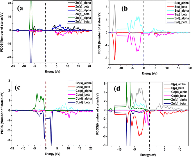 |
| | Fig. 7 (a) Partial density of states of Zn in Co-doped ZnS. (b) Partial density of states of S in Co-doped ZnS. (c) Partial density of states of cobalt in Co-doped ZnS. (d) Partial density of states of Zn, S and Co in Co-doped ZnS. | |
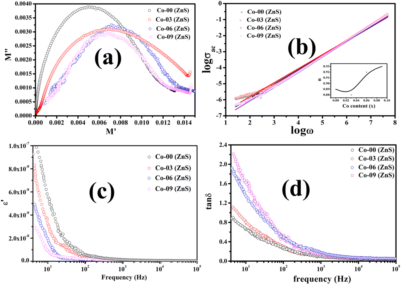
3.9. Analysis of Cole–Cole plots
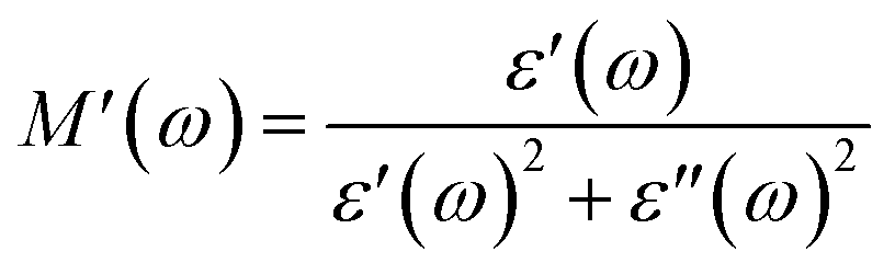
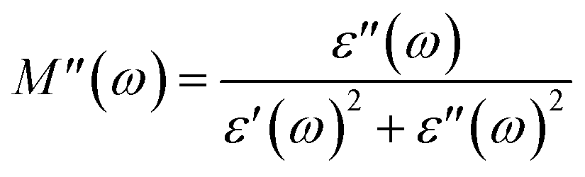
According to Koop's theory, when an oxide dielectric material is subjected to an external ac electric field, the grains and grain boundaries present in the material primarily decide the entire dielectric properties of that material. As per this theory, the grains are conductive, whereas grain boundaries behave exactly the opposite, i.e., non-conductive in nature. Usually, the grain boundaries are considered as a defect in the crystal plane.37–39 The Cole–Cole plot is frequently used to distinguish between the contributions of grains and grain boundaries to the total dielectric response of an oxide dielectric nanomaterial. For formulating the Cole–Cole plot between dielectric moduli, the real and imaginary components of the dielectric constant are used as follows:37–39| | 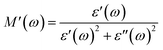 | (6) |
| |  | (7) |
The plotted Cole–Cole graph between the real (M′) and imaginary (M′′) components of dielectric modulus is often semicircular in nature. Fig. 8a displays the Cole–Cole plot of all the doped and undoped ZnS QDs. A close examination found that each sample has only one semicircular curve, which suggests that the resistive grain boundaries contributed more efficiently to the overall conductivity of the prepared oxide QDs than to those of the conductive grains.37–39
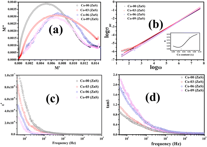 |
| | Fig. 8 (a) Cole–Cole plots, (b) logarithmic plot of conductivity vs. field frequency, (c) semi-logarithmic plot of the real part of dielectric constant vs. field frequency and (d) loss tangent vs. frequency plot of all the QDs. | |
3.10. Studies on electrical conductivity
Electrical conductivity is an inherent property of a material used to understand the elementary charge conduction process of that specific material. The conduction mechanism of electrons for transition metal oxides having a wide band gap upon applied electric field is quite complex rather than a perfect conductor. These transition metal oxide QDs are beneficial for microwave applications because of their wide optical bandgaps and efficient dielectric responses. Normally, when these metal oxide nanomaterials are subjected to an alternating electric field, the charge conduction occurs due to the hopping of electrons.36–40 The applied ac field gives electrons sufficient energy to break through the electrostatic barrier, successfully enabling the hopping process. It is usually seen that the conductivity increases initially for metal oxide nanomaterials with the increase in the applied electric field frequency and then decreases further since the hopping frequency lags behind the field frequency.40,41 This type of behavior for ac electrical conductivity of our prepared QDs was also observed. It is noted that the total electrical conductivity (σt) of transition metal oxide QDs is made up of both dc and ac conductivity parts as follows:36–38| | | σt (T, ω) = σdc (T) + σac (T, ω) | (8) |
where σdc is the dc part of the conductivity, which does not depend on the frequency but on the temperature. Basically, the band conduction of electrons is the origin of dc conductivity of oxide nanomaterials. eqn (8) also mentions another component of electrical conductivity, namely the ac part, which is a frequency- and temperature-dependent component. As shown below, a power law is often obeyed by the ac part of the conductivity:37–39where C(T) becomes a constant for an oxide dielectric material when its temperature and composition is fixed, and n denotes a dimensionless exponent which is permitted to have values between 0 and 1. The charge conduction upon the applied ac field becomes completely frequency independent as the exponent reaches 0. The ac part of the conductivity for all the pure and doped ZnS QDs was recorded at 300 K and a logarithmic graph between ac conductivity and applied frequency was drawn, which is illustrated in Fig. 8b. It is obvious that the logarithmic plot will be a straight line and a linear fit is done to evaluate the slope of the straight line, which provides the value of the exponent. For all the synthesized QDs, the obtained values of the exponent ranged from 0.87 to 0.93 [see the inset of Fig. 8b], indicating that electron hopping occurring at room temperature is the prime charge conduction mechanism.37–39
3.11. Dielectric response analysis
By examining the frequency-dependent real component of dielectric constant, it is possible to comprehend the dielectric properties of oxide QDs together with the capacity to hold charges. This is due of the fact that the real part of the dielectric constant basically measures the developed polarization in the material and directly relates the ability to store the electrical energy. The dielectric responses of each sample were measured at room temperature by changing the frequency of externally applied ac electric field. Fig. 8c demonstrates the real part (ε′) of dielectric constant against applied field frequencies obtained at 300 K in the semi-logarithmic scale for all the pure and Co substituted ZnS QDs. As per Koop's theory, the highly resistive nature of grain boundaries compared to the grains allow the electrons to pile up near the grain boundaries that leads to significant polarizations.38–41 The pristine ZnS QD displays the comparatively high value of ε′ with respect to the doped samples at a low frequency (below 80 Hz), which means that the polarization losses are minimized. With the increment in Co ions in host QDs, the value of ε′ decreases systematically, which implies that the doped materials loss their charge storage capacities gradually. A high value of ε′ indicates that the material must have low polarization loss and be an effective insulator. All the synthesized QDs were unable to hold the polarization as the applied field frequency increases, as they failed to follow the frequency variations.38–41
Another important parameter, i.e., loss tangent which is a ratio of the imaginary component to the real component of dielectric constant, measures the polarization loss of a dielectric material. Dielectric losses are mostly caused by the existence of the point defects, cationic vacancies, grain boundaries, dopants, impurities and lattice imperfections in the dielectric material. The semi-logarithmic plot of loss tangent as a function of ac field frequencies at 300 K was drawn for all the QDs and is shown in Fig. 8d. The polarization loss was found to be prominent at room temperature in all the prepared QDs at a low frequency around 10 Hz. All of the prepared pure and doped QDs demonstrated that the basic charge conduction was caused by electron hopping, and as a result, the polarization loss reached its maximum value when the applied field frequency matched the frequency of electron hopping. Under an applied ac electric field, every single doped and undoped ZnS QD displayed a very comparable pattern of dielectric loss.37–39 The polarization loss was noted to increase gradually for the samples containing higher Co dopants at low frequencies. Beyond 1 kHz field frequency, all the QDs failed to obey the frequency variation, which leads to reduction in the values of loss tangent significantly. When the applied field frequency and the electron hopping frequency were equal, the maximum energy was transmitted. Since all of these nanomaterials demonstrated negligible dielectric loss above 105 Hz frequency, they can be applied to microwave devices.41–43
3.12. BET studies (N2 adsorption/desorption isotherms)
The adsorption–desorption isotherms using N2 gas were recorded for the highest 9% Co-substituted ZnS and pristine ZnS QDs, which are depicted in Fig. S5a and b.† These two QD samples were tested at 250 °C for 18 hours while N2 gas flowed through them. It is established that the surface morphology of a nanosized photocatalyst has a substantial impact on the photodegradation of antibiotics. Other associated parameters that also have a high impact include pore structure, specific surface area, pore diameter and pore volume respectively.21,23 Using Brunauer–Emmett–Teller (BET) analyzer, it was possible to calculate both the specific surface area and pore diameter of these two samples. As the prepared samples were quantum dots having a size well below the Bohr exciton radius, both the isotherms registered for Co-00 (ZnS) and Co-09 (ZnS) samples almost showed a similar nature. When the relative pressure exceeded 0.80, a rapid increment in the adsorption of the isotherm was observed. These two isotherms were found to match with the typical type IV adsorption isotherm, which confirmed the presence of a mesoporous structure.21,44 Due to the strong quantum confinement effect of pure and doped ZnS QDs, there was no significant change in the isotherms and the obtained values of specific surface areas for Co-00 (ZnS) and Co-09 (ZnS) samples are 89.87 m2 g−1 and 93.07 m2 g−1 along with the associated pore radii 3.27 nm and 3.28 nm respectively. All the obtained results from the BET study were also aligned with the X-ray diffraction data.21,23 A histogram is drawn between the specific surface area and the pore radius [see Fig. S5c†], and due to the high surface area of the Co-09 (ZnS) sample, it is able to create enough contact sites for the rapid photodegradation of antibiotics.
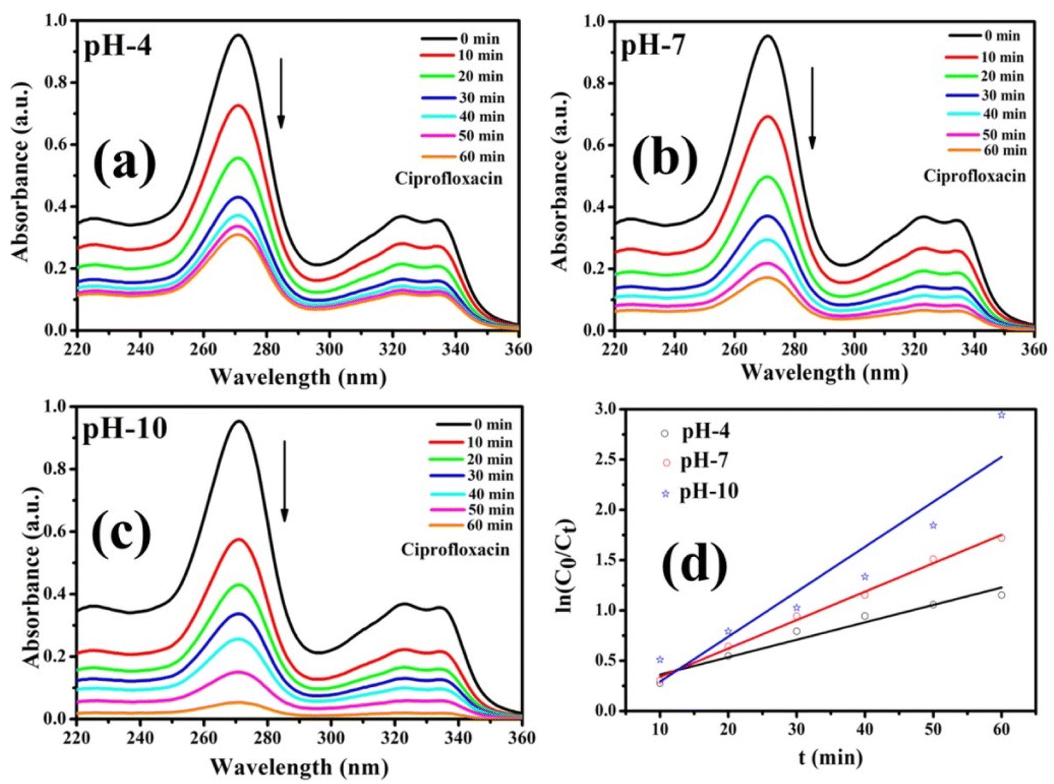
3.13. Photocatalytic degradation of CIP using Co-doped ZnS QDs
A series of photocatalytic studies were conducted for the degradation of the CIP antibiotic under a xenon light source to examine the photocatalytic behavior of the prepared Co-doped ZnS QDs. As a function of illumination time, the UV-vis absorption spectra of the CIP antibiotic (10 mg L−1) were recorded within the wavelength range of 200 and 400 nm [Fig. 9a–c]. The absorbance spectra showed that the CIP absorbance steadily decreases during the course of irradiation. Fig. 10 demonstrates that after 60 minutes of exposure to xenon light, about 94.7% of CIP (1 mg L−1, pH 10) was eliminated in the presence of the photocatalyst, i.e., 9% Co-doped ZnS QDs (10 mg). In Fig. S6 (in ESI),† the evaluation of photodegradation of CIP is shown for pure ZnS QDs and 9% Co-doped ZnS QDs in the darkness without catalyst, in light, and under other conditions with a nanocatalyst dosage of 10 mg for 60 min. The photodegradation efficiency for the CIP antibiotic obtained under various conditions obeyed the following order:
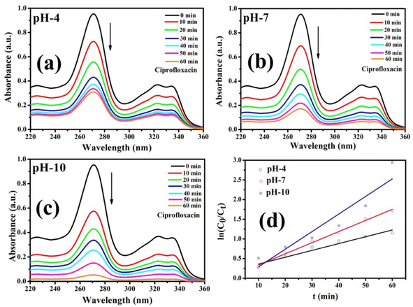 |
| | Fig. 9 (a–c) Photocatalytic degradation of CIP using Co-09 (ZnS) QDs. (d) Graph of rate constant obtained using first-order kinetic reactions. | |
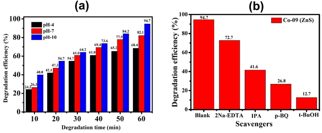 |
| | Fig. 10 (a) Histogram of degradation efficiency at different pH values of the Co-09 (ZnS) sample. (b) Identification of active species using various scavengers. | |
Blank (experiment performed without light and catalyst) < with only light (no catalyst) < with only catalyst (without light) < with both light and catalyst.
3.14. Effect of the pH on the CIP solution
The pH of a solution plays a crucial role in the photocatalytic aqueous oxidation of organic molecules because it influences various photocatalyst properties such as the size of the catalyst particles, the positions of the valence and conductance bands and the charge of the catalyst. In order to familiarise oneself with the impact of pH, degradation studies with 100 mL of 1 mg L−1 starting CIP concentration and 10 mg QDs were conducted at different pH values (4.0–10.0), at room temperature, for 60 minutes. Fig. 10 illustrates how pH levels affect drug deterioration over time. According to expectations, the basic pH levels resulted in faster photocatalytic breakdown of CIP than lower pH values (Fig. 10), which is consistent with other studies using the same treatment.45–47 Although the photocatalytic elimination enhanced as the pH increased, pH 10 produced the highest levels of adsorption and degradation. Actually, the primary factors influencing this behavior are the surface charges of the CIP and the Co-doped ZnS QD catalyst. Since ZnS has a point of zero charge (pHzpc) between 7 and 7.5, its surface charge becomes negative above pH 7, whereas positive below pH 7.48 Ciprofloxacin, however, contains two different ionizable functional groups, the 6-carboxylic group and the N-4 group of the piperazine substituent, resulting in two discrete ionization constants: pKa1 (pH = 6.34), caused by deprotonation from the carboxyl moiety, and pKa2 (pH = 8.75), caused by protonation to N4 in the piperazine substituent. As a result, CIP exhibits a positively charged behavior below pH 6.34, a negative behavior above pH 8.75, and a zwitterionic behavior between these two pH ranges.49,50 Both the CIP and Co-doped ZnS QDs are controlled by a positive charge in an acidic solution. Similar charges exhibited a repulsive behaviour, which limits CIP's ability to interact with the QD surface and lowers the rate of deterioration. The degrading reaction is accelerated by the attractive interaction between the 6-carboxyl group and the QDs.51 The pH values between 9.5 and 10.5 are ideal for CIP degradation since they are just slightly above the pKa2 threshold. This might be due to an increase in the amount of hydroxyl anions (OH−), which provides hydroxyl radicals during the photocatalytic reactions. The production of hydroxyl radicals (OH˙) will increase with the increase in OH− ion concentration.52 As a result, pH 10 was chosen as the ideal pH level for additional research.
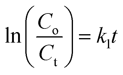
3.15. Kinetics studies
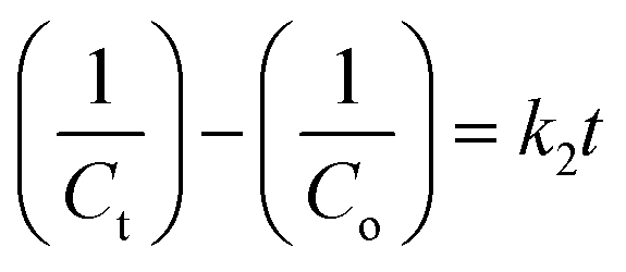
For each sample, the rate constant of the photodegradation process was estimated, which is another crucial component. First-order and second-order rate equations were used to investigate the photodegradation of CIP employing 9% Co-doped ZnS QD catalysts as follows:52,53| |  | (10) |
| | 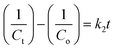 | (11) |
where both Co and Ct indicate the initial and final concentrations of CIP, t represents the xenon light exposure period, k1 represents the first-order reaction rate kinetics, and k2 represents the second-order reaction rate kinetics. These two rate equations were further plotted against time for each sample to recognize the reaction kinetics, yielding straight-line graphs. Both Fig. 9d and S7 (in ESI)† illustrate the kinetic graphs of the photodegradation processes. The order of the reactions is determined by the regression correlation coefficient (R2) of the kinetics plots of all samples, and the rate constant is given by the slope of the straight line. Table S4 (in ESI)† contains the estimated R2 values for the two orders of kinetics that obey eqn (10) and (11). The acquired values of R2 for first-order kinetics are understood to be greater than those for second-order kinetics, as shown in Table S4 (in ESI),† showing that the photodegradation of CIP obeys the first-order rate kinetics. The acquired values of rate constants for the 9% Co-doped ZnS QD sample at various pH values of 4, 7, and 10 were 0.017 min−1, 0.028 min−1 and 0.044 min−1 respectively. It is also found that the rate constants of blank (experiment performed without light and catalyst), with only light (no catalyst) and with only catalyst (without light) are 0.0003 min−1, 0.0021 min−1 and 0.0052 min−1 respectively.
3.16. Role of active oxidation species
By incorporating 0.01 M of suitable scavengers of these species, the formation and roles of reactive species, such as h+,  , OH˙, and e− for CIP degradation were investigated, as shown in Fig. 10b. To identify the respective active species, various scavengers are utilised, including tert-BuOH, isopropyl alcohol, disodium ethylenediaminetetraacetate (2Na-EDTA), and p-benzoquinone (p-BQ). We know that superoxide (
 ) radicals, holes (h+), electrons (e−), and hydroxyl radicals (OH˙) are scavenged by p-BQ, EDTA, IPA, and tert-BuOH, respectively.54–57 Prior to the nanocatalyst addition, the scavengers were used. In the absence of any scavenger, the maximum CIP degradation (94.7%) was recorded. However, when IPA and EDTA were added, the photodegradation efficiency was hindered by 41.6% and 72.7%, respectively. Additionally, the introduction of t-BuOH and p-BQ significantly reduced the efficiency of CIP degradation to 12.7% and 26.8%, respectively, demonstrating that OH˙ and
  were significant reactive species and played a crucial role in CIP degradation over the Co-doped ZnS QDs catalysts.
3.17. Potential photocatalytic mechanism for photocatalyst degradation
When exposed to light having energy equivalent to or slightly higher than its optical bandgap, the semiconductor photocatalyst can be stimulated.58,59 Therefore, the excitation within the QDs, which causes the generation of the electron–hole pairs at the QD surface, is the first step in the potential mechanism for the xenon light-assisted photodegradation of CIP. These e− and h+ can be either recombined or floated to the surface, resulting in photoactive centers.60 In fact, the total amount of charge carriers (e− and h+) at the nanosized photocatalyst surface impacts the degradation efficiency. Because of its high oxidation potential, h+ can either indirectly or directly oxidise organic materials (CIP Drug). All the reactive hydroxide radicals (OH˙) are formed during indirect oxidation as a result of the interaction of h+ with H2O or with hydroxide anions,61 as illustrated in the following equations:| | | QD + hv → QD (e− + h+) | (12) |
| | | h+ + Drug → Oxidation of drug | (13) |
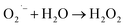
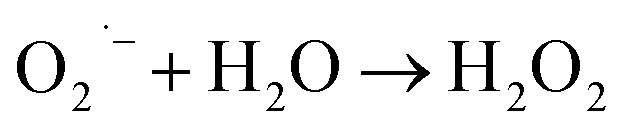
This OH˙ is a powerful oxidant (E = +3.06 V) that partially or totally oxidizes pharmaceuticals and other organic materials to mineral species. Additionally, oxygen atoms and the doped metal at the surface act as a sink for e−, improving the separation of electron–hole pairs. The surface conduction band e− of ZnS could convert molecular oxygen (O2) into superoxide anion ( ). Then O2 interacts with H2O to form H2O2, which further produces OH˙ radicals.62
| |  | (16) |
| |  | (17) |
The h+, e−, OH˙, and  themselves play substantial roles in the photodegradation pathway, depending on the specific experimental condition.63 As a result, organic matter mineralization can result from the OH˙ radical produced by e− in the conduction band, among other stages:
| | | HO˙ + Drug molecules → Degradation of Drug | (19) |
| |  | (20) |
The photocatalytic degradation is improved when the catalyst is doped with transition metal ions because more OH˙ and  are formed. Doping allows charge carriers (e− and h+) to be trapped, expanding their lives, and therefore, increasing photocatalytic efficiency.64
4. Conclusion
In summary, this study accurately accomplished the photocatalytic efficiency along with detailed investigations on the microstructural, magnetic, optical, and dielectric properties of Co-doped ZnS [Zn1−xCoxS: x = 0.0, 0.03, 0.06 and 0.09] QDs. Four QD samples were fabricated by the common chemical co-precipitation method, each with a different Co dopant. The average crystallite sizes of all the QDs were found to be 1.1 ± 0.1 nm calculated using Scherrer's formula. Due to the mismatch in ionic radii between Co and Zn ions, the lattice constant consistently decreased as the Co content in ZnS nanocrystals increased. All the prepared QDs displayed remarkable size and shape homogeneity, which was supported by the HRTEM micrographs. The high nanocrystalline nature of the synthesized QDs was further supported by the SAED pattern. A gradual increase in the direct optical band gap was also noted with the increase in Co percentages in ZnS QDs, which indicates the confinement effect compared to pristine ZnS. FDTD simulations were also carried out to understand the blue shift in the absorption spectra of the synthesized QDs. The behavior of formed chemical bonds in the compounds was understood from the FTIR spectra. According to the PL results, cobalt doping in ZnS quantum dots increases the luminescence intensity. This increase is a result of the Co ions being successfully incorporated into the ZnS lattice. The charge transfer process of all the QD samples is electron hopping as per the electrical conductivity analysis. A thorough analysis of the dielectric characteristics of all the samples showed that the grain boundaries were more important in producing the overall dielectric response. The dielectric loss tangent became more prominent at low frequencies for the samples containing more Co ions. A weak ferromagnetic behavior at room temperature was successfully incorporated into the host ZnS QDs using magnetic Co dopants. The p–d hybridization between the 3d levels of Co2+ ions and the 3p levels of S2− ions in the host ZnS QDs was primarily responsible for the observed weak ferromagnetic behavior. This weak ferromagnetic nature of doped QDs was confirmed by hysteresis loops that were measured at room temperature. Theoretically, the DFT computations supported the obtained results of weak ferromagnetism. In order to understand the photocatalytic efficiency, the specific surface area and pore size of the doped ZnS QDs were obtained using the N2 adsorption/desorption isotherms. A pH-dependent study of CIP photodegradation revealed that the Co-09 (ZnS) sample performed extremely well in a basic medium to degrade the CIP antibiotic. Then this work revealed that all these synthesized Co-doped ZnS QDs are greatly promising nanomaterials for the photodegradation of antibiotics, and are ideal diluted magnetic semiconductors in future spintronic devices.
Author contributions
RS: methodology, simulation work, formal analysis, writing part of the original draft, and writing – review and editing. NJM: methodology, investigation, formal analysis, discussion, writing original draft, and writing – review and editing. ST: methodology, simulation work, writing part of the original draft and editing. ES: methodology and discussion. MPG: conceptualization, methodology, resources, supervision, discussion, writing part of the original draft, writing review and editing. DC: conceptualization, methodology, validation, resources, supervision, discussion, and writing review and editing.
Conflicts of interest
Authors declare that they have no known competing financial interests or personal relationships that could have appeared to influence the work reported in this paper.
Acknowledgements
RS would like to thank UGC, New Delhi for the fellowship, NJM thank CSIR, New Delhi for the fellowship. The authors would like to extend their sincere appreciation to Dr Nirab C. Adhikary for fruitful discussions on DFT simulation. All the authors thank IASST, Guwahati for in-house project and SAIC-IASST for providing instrumental facilities.
References
- V. Abramov, A. Abramova, V. Bayazitov, S. Kameneva, V. Veselova, D. Kozlov, M. Sozarukova, A. Baranchikov, I. Fedulov, R. Nikonov and G. Cravotto, Processes, 2022, 10, 2063 CrossRef CAS.
- I. Mukherjee, V. Cilamkoti and R. K. Dutta, ACS Appl. Nano Mater., 2021, 4, 7686–7697 CrossRef CAS.
- M. T. Kiani, A. Ramazani and S. Taghavi Fardood, Appl. Organomet. Chem., 2023, 37, e7053 CrossRef CAS.
- S. Shehu Imam, R. Adnan and N. H. Mohd Kaus, Toxicol. Environ. Chem., 2018, 100, 518–539 CrossRef CAS.
- S. B. Verinda, M. Muniroh, E. Yulianto, N. Maharani, G. Gunawan, N. F. Amalia, J. Hobley, A. Usman and M. Nur, Heliyon, 2022, 8, e10137 CrossRef CAS.
- L. Li, J. Liu, J. Zeng, J. Li, Y. Liu, X. Sun, L. Xu and L. Li, Nanomaterials, 2021, 11, 1660 CrossRef CAS.
- T. Montalvo-Herrera, D. Sánchez-Martínez and L. M. Torres-Martínez, J. Chem. Technol. Biotechnol., 2017, 92, 1496–1502 CrossRef CAS.
- D. Pinheiro, K. R. Sunaja Devi, A. Jose and K. Karthik, Int. J. Environ. Sci. Technol., 2020, 18, 2303–2324 CrossRef.
- J. M. Jacob, R. Rajan, M. Aji, G. G. Kurup and A. Pugazhendhi, Ceram. Int., 2019, 45, 4857–4862 CrossRef CAS.
- R. N. Juine, B. K. Sahu and A. Das, New J. Chem., 2021, 45, 5845–5854 RSC.
- A. R. Amani-Ghadim, S. Arefi-Oskoui, R. Mahmoudi, A. T. Sareshkeh, A. Khataee, F. Khodam and M. S. Seyed Dorraji, Chemosphere, 2022, 295, 133917 CrossRef CAS.
- D. Saikia and J. P. Borah, Appl. Phys. A, 2018, 124, 240 CrossRef.
- M. Bilal, M. Shafiq, I. Ahmad and I. Khan, J. Semicond., 2014, 35, 072001 CrossRef CAS.
- I. Khan, I. Ahmad, H. A. Rahnamaye Aliabad and M. Maqbool, J. Appl. Phys., 2012, 112, 073104 CrossRef.
- B. Poornaprakash, U. Chalapathi, P. T. Poojitha, S. V. P. Vattikuti and S.-H. Park, J. Supercond. Novel Magn., 2019, 33, 539–544 CrossRef.
- S. Roy, M. P. Ghosh and S. Mukherjee, Appl. Phys. A, 2021, 127, 451 CrossRef CAS.
- L. K. Sharma and S. Mukherjee, J. Electron. Mater., 2016, 46, 1270–1278 CrossRef.
- M. P. Ghosh and S. Mukherjee, J. Am. Ceram. Soc., 2019, 102, 7509–7520 CrossRef CAS.
- E. D. Gaspera, J. Griggs, T. Ahmed, S. Walia, E. L. H. Mayes, A. Calzolari, A. Catellani and J. van Embden, Nanoscale, 2019, 11, 3154 RSC.
- Z. Ž. Lazarević, Č. Jovalekić, D. L. Sekulić, A. Milutinović, S. Baloš, M. Slankamenac and N. Ž. Romčević, Mater. Res. Bull., 2013, 48, 4368–4378 CrossRef.
- N. J. Mondal, R. Sonkar, B. Boro, M. P. Ghosh and D. Chowdhury, Nanoscale Adv., 2023, 5, 5460–5475 RSC.
- M. Sundararajan, V. Sailaja, L. John Kennedy and J. Judith Vijaya, Ceram. Int., 2017, 43, 540–548 CrossRef CAS.
- A. Makofane, D. E. Motaung and N. C. Hintsho-Mbita, Ceram. Int., 2021, 47, 22615–22626 CrossRef.
- R. Mohan, M. P. Ghosh and S. Mukherjee, J. Magn. Magn. Mater., 2018, 458, 193–199 CrossRef CAS.
- S. Gupta, R. K. Choubey, L. K. Sharma, M. P. Ghosh, M. Kar and S. Mukherjee, Semicond. Sci. Technol., 2019, 34, 105006 CrossRef CAS.
- M. P. Ghosh and S. Mukherjee, J. Magn. Magn. Mater., 2019, 489, 165320 CrossRef CAS.
- S. Singhal, S. Bhukal, J. Singh, K. Chandra and S. Bansal, J. Nanotechnol., 2011, 2011, 1–6 CrossRef.
- N. J. Mondal, R. Sonkar, S. Thakur, N. Ch. Adhikary and D. Chowdhury, ACS Appl. Nano Mater., 2023, 6, 7351–7363 CrossRef CAS.
- P. V. Radovanovic and D. R. Gamelin, J. Am. Chem. Soc., 2001, 123, 12207–12214 CrossRef CAS.
- W. Q. Peng, G. W. Cong, S. C. Qu and Z. G. Wang, Opt. Mater., 2006, 29, 313–317 CrossRef CAS.
- B. Poornaprakash, D. Amaranatha Reddy, G. Murali, N. Madhusudhana Rao, R. P. Vijayalakshmi and B. K. Reddy, J. Alloys Compd., 2013, 577, 79–85 CrossRef CAS.
- L. Liu, L. Yang, Y. Pu, D. Xiao and J. Zhu, Mater. Lett., 2012, 66, 121–124 CrossRef CAS.
- S. Sambasivam, D. Paul Joseph, J. G. Lin and C. Venkateswaran, J. Solid State Chem., 2009, 182, 2598–2601 CrossRef CAS.
- H.-Q. Xie, L.-J. Tang, J.-L. Tang and P. Peng, J. Magn. Magn. Mater., 2015, 377, 239–242 CrossRef CAS.
- B. Cordero, V. Gómez, A. E. Platero-Prats, M. Revés, J. Echeverría, E. Cremades, F. Barragán and S. Alvarez, Dalton Trans., 2008, 2832, 2838 Search PubMed.
- W. M. Malisoff, Philos. Sci., 1941, 8, 133 CrossRef.
- M. Aakash, P. Ghosh and S. Mukherjee, Appl. Phys. A, 2019, 125, 853 CrossRef CAS.
- M. P. Ghosh, S. Kinra, D. Dagur, R. K. Choubey and S. Mukherjee, Phys. Scr., 2020, 95, 095812 CrossRef CAS.
- M. P. Ghosh, S. Datta, R. Sharma, K. Tanbir, M. Kar and S. Mukherjee, J. Mater. Sci. Eng. B, 2021, 263, 114864 CrossRef CAS.
- A. Nihore, F. Aziz, N. Oswal, P. Jain, O. Subohi and N. Gupta, Mater. Today: Proc., 2019, 18, 3651–3656 CAS.
- D. Varshney and K. Verma, Mater. Chem. Phys., 2013, 140, 412–418 CrossRef CAS.
- K. Omri, A. Bettaibi, K. Khirouni and L. El Mir, Phys. B, 2018, 537, 167–175 CrossRef CAS.
- V. L. Rao, Y. V. Reddy, T. S. Kumar, N. P. Kumar, B. P. Kunta and M. Nagabhushanam, Solid State Commun., 2023, 360, 115052 CrossRef CAS.
- J. Gogoi and D. Chowdhury, Mater. Adv., 2023, 4, 2088–2098 RSC.
- A. Alam, W. U. Rahman, Z. U. Rahman, S. A. Khan, Z. Shah, K. Shaheen, H. Suo, M. N. Qureshi, S. B. Khan, E. M. Bakhsh and K. Akhtar, J. Mater. Sci.: Mater. Electron., 2022, 33, 4255–4267 CrossRef CAS.
- S. Das, S. Ghosh, A. Misra, A. Tamhankar, A. Mishra, C. Lundborg and S. Tripathy, Int. J. Environ. Res. Public Health, 2018, 15, 2440 CrossRef CAS.
- S. Shurbaji, P. T. Huong and T. M. Altahtamouni, Catalysts, 2021, 11, 437 CrossRef CAS.
- H. R. Pouretedal, A. Norozi, M. H. Keshavarz and A. Semnani, J. Hazard. Mater., 2009, 162, 674–681 CrossRef CAS.
- A. Maged, S. Kharbish, I. S. Ismael and A. Bhatnagar, Environ. Sci. Pollut. Res., 2020, 27, 32980–32997 CrossRef CAS.
- L. Valdés, I. Pérez, L. C. de Ménorval, E. Altshuler, J. O. Fossum and A. Rivera, PLoS One, 2017, 12, e0187879 CrossRef.
- G. D'Andrea and G. Di Nicolantonio, J. Chem. Educ., 2002, 79, 972 CrossRef.
- N. M. Mahmoodi, M. Arami, N. Y. Limaee and N. S. Tabrizi, J. Colloid Interface Sci., 2006, 295, 159–164 CrossRef CAS.
- K. K. Onyechi and C. A. Igwegbe, Asian J. Res. Med. Pharm. Sci., 2019, 6, 1–17 Search PubMed.
- Y.-C. Lin, K.-W. Hsiao and A. Y.-C. Lin, Environ. Sci. Pollut. Res., 2017, 25, 2303–2312 CrossRef.
- Y. Liu, Y. Ma, J. Wan, Y. Wang, J. Sun and Y. Xue, Environ. Sci. Pollut. Res., 2021, 28, 43815–43830 CrossRef CAS.
- C. Sarangapani, D. Ziuzina, P. Behan, D. Boehm, B. F. Gilmore, P. J. Cullen and P. Bourke, Sci. Rep., 2019, 9, 3955 CrossRef.
- X. Zheng, J. Yuan, J. Shen, J. Liang, J. Che, B. Tang, G. He and H. Chen, J. Mater. Sci.: Mater. Electron., 2019, 30, 5986–5994 CrossRef CAS.
- N. Kaur, J. Singh, S. Kumar, P. Singh, S. Al-Rashed, H. Kaur and M. Rawat, J. Mater. Sci.: Mater. Electron., 2020, 31, 21233–21247 CrossRef CAS.
- H. R. Pouretedal, A. Norozi, M. H. Keshavarz and A. Semnani, J. Hazard. Mater., 2009, 162, 674–681 CrossRef CAS.
- L. Sun, C. Liu, C. Liao and C. Yan, J. Mater. Chem., 1999, 9, 1655–1657 RSC.
- M. Montazerozohori, M. Nasr-Esfahani and S. Joohari, Environ. Prot. Eng., 2012, 38, 45–55 CAS.
- K. Kumar, M. Chitkara, I. Singh Sandhu, D. Mehta and S. Kumar, Mater. Sci. Semicond. Process., 2015, 30, 142–151 CrossRef CAS.
- A. Fujishima and X. Zhang, C. R. Chim., 2006, 9, 750–760 CrossRef CAS.
- M. A. Barakat, H. Schaeffer, G. Hayes and S. Ismat-Shah, Appl. Catal., B, 2005, 57, 23–30 CrossRef CAS.
|
| This journal is © The Royal Society of Chemistry 2023 |
Click here to see how this site uses Cookies. View our privacy policy here. 
 Open Access Article
 This Open Access Article is licensed under a Creative Commons Attribution-Non Commercial 3.0 Unported Licence
 ab,
Nur Jalal
Mondal
ab,
Nur Jalal
Mondal


 where ‘d’ is the thickness of the container. The minimum energy required for direct optical transition, i.e., direct band gap (Eo) for all the samples was estimated using a graph drawn between (αhν)2 and hν, which is known as the Tauc plot and is shown in Fig. S1 (in ESI).† The values of Eo for all the prepared Co-doped and pure ZnS QDs are tabulated in Table S2 (in ESI)† respectively. The obtained values of direct bandgap for both the pristine and doped ZnS QDs were slightly greater than that of the bulk ZnS. It is due to the fact of strong confinement effects.25 A systematic increase in the optical band gap was also noted for the samples having more Co dopants, which clearly indicates a better confinement effect than that of pristine ZnS QDs. It is easily understood by analyzing the absorption spectra of all the QDs that all the samples revealed an opaque nature in the UV region of the electromagnetic spectrum. A significant blue shift in the absorption of EM wave was also observed for a higher Co content of QDs. All of the fabricated QDs are appropriate for use in optical applications due to their exceptional UV band absorption qualities.21,26
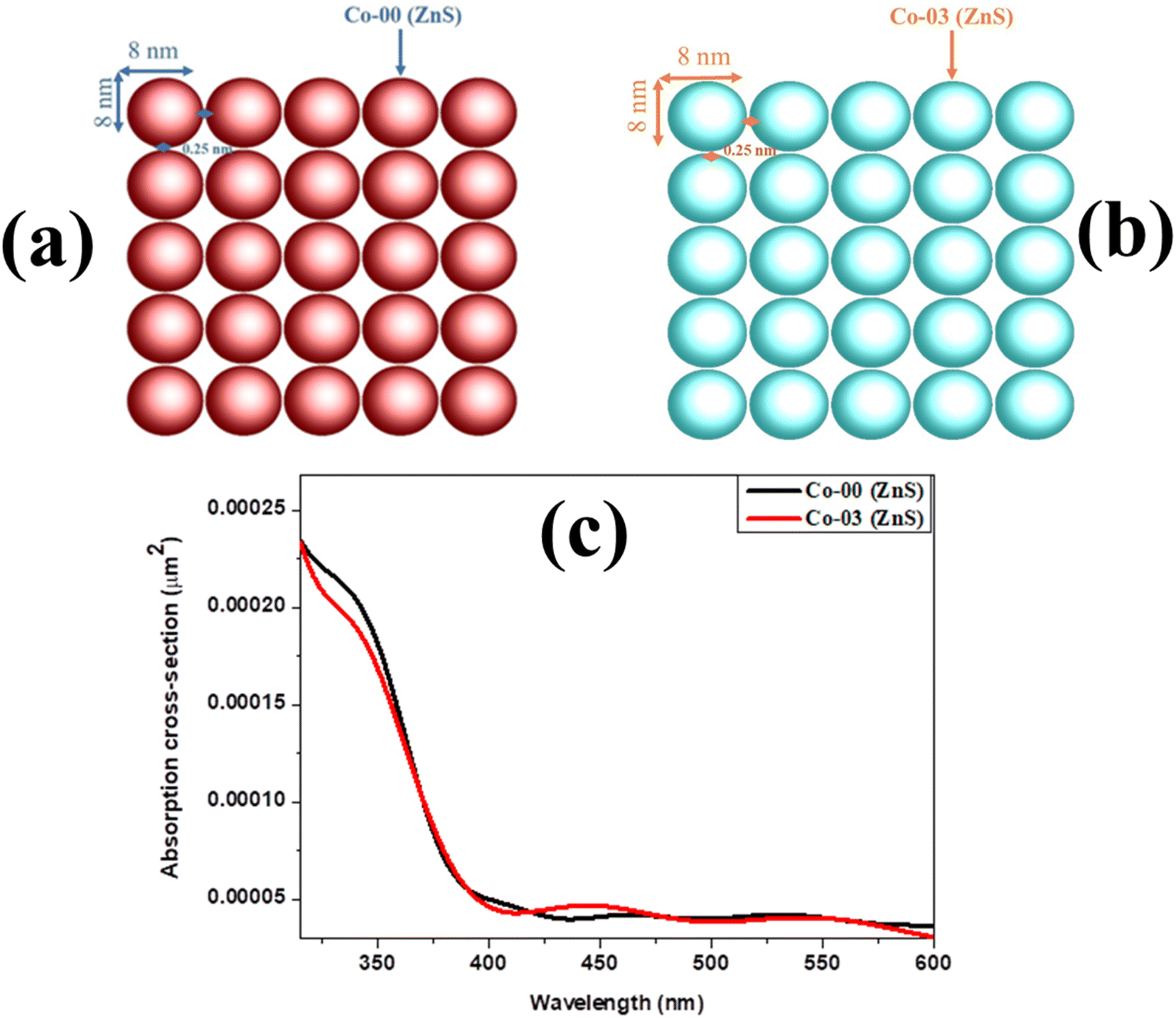

 , OH˙, and e− for CIP degradation were investigated, as shown in Fig. 10b. To identify the respective active species, various scavengers are utilised, including tert-BuOH, isopropyl alcohol, disodium ethylenediaminetetraacetate (2Na-EDTA), and p-benzoquinone (p-BQ). We know that superoxide (
 ) radicals, holes (h+), electrons (e−), and hydroxyl radicals (OH˙) are scavenged by p-BQ, EDTA, IPA, and tert-BuOH, respectively.54–57 Prior to the nanocatalyst addition, the scavengers were used. In the absence of any scavenger, the maximum CIP degradation (94.7%) was recorded. However, when IPA and EDTA were added, the photodegradation efficiency was hindered by 41.6% and 72.7%, respectively. Additionally, the introduction of t-BuOH and p-BQ significantly reduced the efficiency of CIP degradation to 12.7% and 26.8%, respectively, demonstrating that OH˙ and
 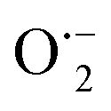 were significant reactive species and played a crucial role in CIP degradation over the Co-doped ZnS QDs catalysts.
 ). Then O2 interacts with H2O to form H2O2, which further produces OH˙ radicals.62
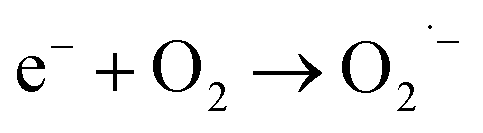
 themselves play substantial roles in the photodegradation pathway, depending on the specific experimental condition.63 As a result, organic matter mineralization can result from the OH˙ radical produced by e− in the conduction band, among other stages:
 are formed. Doping allows charge carriers (e− and h+) to be trapped, expanding their lives, and therefore, increasing photocatalytic efficiency.64