 Open Access Article
Preparation of boron nitride nanosheets by glucose-assisted ultrasonic cavitation exfoliation
Lian
Zhou
,
Bo
Zhang
,
Fuzhu
Li
 *,
Ying
Yan
,
Yun
Wang
and
Ruitao
Li
Jiangsu University, China. E-mail: lifuzhu@ujs.edu.cn
First published on 3rd November 2023
Abstract
Boron nitride nanosheets (BNNSs) have been widely used in many fields due to their excellent properties. However, low preparation rates and difficulty in functionalization hinder their further development. This study proposes a novel glucose-assisted ultrasonic cavitation exfoliation (GAUCE) method with glucose as an auxiliary solution to prepare BNNSs. Results show that the method has a high preparation yield of 55.58%, which is higher than the average preparation yield of 33.86%. The mechanism of preparing BNNSs by GAUCE was also investigated. The exfoliation of BNNSs was achieved using the energy of ultrasonic cavitation bubble collapse, which will break the interlayer forces in h-BN. The grafting of hydroxyl groups decomposed by glucose on the edge and surface of BNNSs during cavitation prevented the re-aggregation of the nanosheets, thereby increasing the exfoliation yield of BNNSs. In addition, the contact angle of BNNSs prepared by GAUCE was reduced, and the hydrophilicity was greatly improved.
1 Introduction
Hexagonal boron nitrides (h-BN) are widely used in fields such as sensors,1 hydrogen storage,2 catalysis3 and sewage treatment4 due to their excellent physical and chemical properties. Recent studies have shown that few-layered boron nitride nanosheets (BNNSs) can effectively exert the excellent properties of h-BN. For example, the thermal conductivity of BNNSs is 400–2000 W m−1 K−1, which is two to five times more than that of h-BN.5 However, the exfoliation energy of h-BN is ≈33% higher than that of graphite,6 so the large-scale preparation of BNNSs has become a great technical challenge. In addition, BNNSs also need to be adequately functionalized to achieve the best performance of their composites.7Up to now there have primarily been two strategies to obtain BNNSs: bottom-up and top-down methods.8 In bottom-up methods, BNNSs are usually synthesized directly by chemical techniques, which usually produces functionalized BNNSs. Yu9 and Nadeem et al.10 used the chemical vapor deposition (CVD) method to deposit BNNS films on a silicon substrate and low-carbon steel substrates, respectively. High-quality BNNSs are prepared by this method. However, low yield, critical synthetic conditions and the risk of environmental pollution have limited its development. Liu et al.11 synthesized BNNSs by the wet chemical method, and the yield was up to 96.7%. However, this approach is expensive and difficult to operate, so it is unsuitable for the large-scale preparation of BNNSs. Top-down methods use shear force to exfoliate BNNSs from bulk h-BN, and are more suitable for the large-scale production of BNNSs. Mechanical exfoliation,12 fluid exfoliation13 and ultrasonic cavitation exfoliation14 are the three main top-down methods. Pacilé et al.15 successfully prepared BNNSs by mechanical exfoliation, but this method has a low yield. Therefore, ball milling mechanical exfoliation was developed. Wang et al.16 selected viscous polyethyleneimine (PEI) as the ball milling auxiliary solution to prepare BNNSs and achieve scalable production. Chen et al.17 selected sucrose as the ball milling auxiliary solution to prepare BNNSs, and the results showed that the yield can reach 95% and the surface of the prepared BNNSs would be grafted with hydroxyl-functionalized groups.
Cavitation is a phase change phenomenon (from liquid to gas) by decreasing the pressure due to an increase in velocity.18 The use of energy released by cavitation bubble collapse to break the ‘lip–lip’ interactions of h-BN provides an avenue for the high-efficiency exfoliation of BNNSs.19 Lin et al.20 reported that pure-water-assisted ultrasonic cavitation could exfoliate h-BN in a small amount. Zhi et al.14 obtained BNNSs by using N-dimethylformamide (DMF) as an exfoliating solvent to ultrasonically treat h-BN. However, the yield of BNNSs is only 5%. Ding et al.21 obtained BNNSs with a yield of 33% by using liquid N2 as an ultrasonic exfoliating solvent. The selection of exfoliating solvent is important when preparing BNNSs by ultrasonic cavitation exfoliation. An et al.22 reported that N-methyl-pyrrolidone (NMP), N,N-dimethylformamide (DMF), and isopropanol (IPA) are effective solvents for exfoliation. Compared with the above solvents, glucose is noncorrosive, bio-renewable and cheap, and can be easily recycled. It is suitable for large-scale application in industrial production. Li et al.23 proposed a scalable exfoliating and functionalized approach via temperature pretreatment and glucose-assisted mechanical agitation to achieve a high actual exfoliation yield (47%) of BNNSs. However, the yield from this method needs to be further improved.
This study proposes a novel glucose-assisted ultrasonic cavitation exfoliating (GAUCE) method to prepare BNNSs. The method uses glucose as an auxiliary solution, and BNNSs prepared by deionized-water-assisted ultrasonic cavitation exfoliation were used as a control. The structure and morphology of the BNNSs were observed, and the mechanism of BNNSs prepared by GAUCE was investigated. Finally, contact angle and dispersion testing were used to evaluate the hydrophilicity and dispersibility of BNNSs prepared by ultrasonic exfoliation.
2 Experimental apparatus
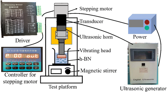
Fig. 1 shows the GAUCE experimental apparatus, which was designed and developed to exfoliate BNNSs. The apparatus consists of an ultrasonic generator, a stepping motor, a transducer, an ultrasonic horn, a vibrating head, magnetic stirrers and a controller for the stepping motor. The magnetic stirrer is placed directly below the ultrasonic vibration head. It is used to mix the original h-BN powder with the glucose exfoliating solvent. The ultrasonic transducer converts electrical signals emitted by the ultrasonic generator into periodic high-frequency mechanical vibrations. The amplitude is transmitted to the ultrasonic vibration head under the action of the horn. The ultrasonic wave generated by the ultrasonic vibration head acts on the mixed solution to produce ultrasonic cavitation, thereby exfoliating h-BN.3 Method and measurements
3.1 Raw materials
h-BN powder with a purity of 99.9% was obtained from Beijing Xingrongyuan Technology Co., Ltd. Anhydrous glucose AR with a purity of 99.5% was acquired from China National Pharmaceutical Group Chemical Reagent Co., Ltd. A Millipore nylon filter membrane with a pore size of 0.20 μm was used. All chemicals used were of analytical grade and used without further treatment.3.2 GAUCE process
The GAUCE process is shown in Fig. 2. Firstly, 2 g of anhydrous glucose was added to 250 ml of deionized water to prepare a glucose solution. To the solution was then added 5 g of h-BN and it was stirred using a magnetic stirrer at 1000 rpm for 10 minutes to form a homogeneous solution. The mixture was subjected to ultrasonic treatment at 310 W for 30 minutes to obtain a dispersed solution of glucose–BNNSs. The dispersed solution was filtered and washed using a dialysis bag to obtain a dispersed solution of BNNSs. The solution was centrifuged at 3000 rpm for 20 minutes, and the supernatant was collected and dried to obtain exfoliated BNNSs, which were then weighed. A control experiment was conducted without glucose in 250 ml of deionized water, and the product obtained from ultrasonic exfoliation in this case was denoted W-BNNSs. The product obtained using GAUCE was denoted G-BNNSs.3.3 Testing and characterization
Field emission scanning electron microscopy (JSM-7800F) was used to observe the surface morphology and lateral size distribution of h-BN and ultrasonically exfoliated BNNSs. Atomic force microscopy (Bruker Dimension Icon) was utilized to observe the thickness and lateral size distribution of the BNNSs. Transmission electron microscopy (FEI Talos F200X G2) was employed to investigate the microstructure and crystallinity of the BNNSs. X-ray diffraction (BRUKER) was used to analyze the crystal structure and elemental composition of the BNNSs. Fourier transform infrared spectroscopy (IRAffinity-1S) was used to characterize the functional groups and functional group attachment sites of the BNNSs. X-ray photoelectron spectroscopy (Thermo Scientific K-Alpha) was utilized to analyze the functional group attachment sites and quantify the number of functional groups in the BNNSs. Contact angle and dispersion testing were used to evaluate the hydrophilicity and dispersibility of BNNSs prepared by ultrasonic exfoliation.4 Results
4.1 Effect of GAUCE on the yield of boron nitride nanosheets
The yield of BNNSs prepared by ultrasonic exfoliation with deionized water was 33.86%, while that prepared by the GAUCE method was 55.58%. Fig. 3 presents a comparison of the yield of BNNSs prepared by GAUCE with the yields obtained using the CVD method, ball milling mechanical exfoliation and ultrasonic cavitation exfoliation methods. Fig. 3 shows that the ultrasonic cavitation exfoliation method can obtain a higher percentage of BNNSs within a relatively short ultrasonic processing time. The high temperature and pressure generated during cavitation overcome the interlayer ‘lip–lip’ interactions and van der Waals forces in the edge and inner layers of h-BN, thereby reducing the interlayer forces. The strong interaction between glucose and water molecules during cavitation leads to the release of hydroxyl groups, which enter the interlayers of h-BN. The process facilitates the exfoliation process and obtains few-layered BNNSs from bulk h-BN.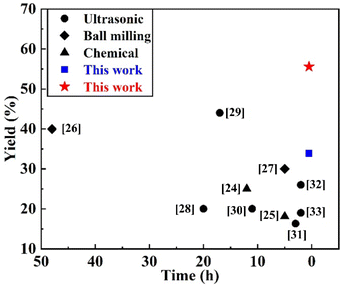 | ||
| Fig. 3 Yield of BNNSs prepared by GAUCE and other methods in the literature.24–33 | ||
4.2 Influence of GAUCE on the quality of BNNSs
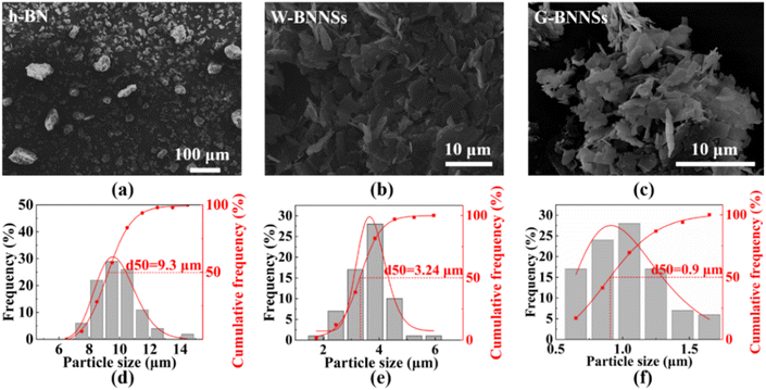
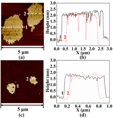
Fig. 4 shows the microscopic morphology of h-BN, W-BNNSs, and G-BNNSs. In Fig. 4(a)–(c), the pristine h-BN powder appears as granular particles with strong aggregation, while W-BNNSs and G-BNNSs exhibit a sheet-like morphology and are more dispersed. After processing the lateral size data, the average lateral size of pristine h-BN powder was found to be approximately 9.3 μm, as shown in Fig. 4(d). This finding is consistent with the initial average particle size of the purchased h-BN powder of approximately 10 μm. In comparison with pristine h-BN powder, W-BNNSs and G-BNNSs exhibited a significant reduction in lateral size. The average particle sizes of W-BNNSs and G-BNNSs are 3.24 μm, and 0.9 μm, respectively. Overall, the average particle size decreased by 65% and 90% for W-BNNSs and G-BNNSs, respectively, as shown in Fig. 4(e) and (f). Deionized-water-assisted ultrasonic exfoliation and glucose-assisted ultrasonic exfoliation can effectively exfoliate bulk h-BN into nanosheets, which exhibit a sheet-like morphology. Compared to pristine h-BN powder, both W-BNNSs and G-BNNSs demonstrate a significant reduction in thickness.Fig. 5 shows the AFM images and thickness distribution of W-BNNSs and G-BNNSs. The lateral size distribution of W-BNNSs and G-BNNSs can be observed from Fig. 5(a) and (c), respectively. The AFM images of W-BNNSs and G-BNNSs were processed using NanoScope Analysis software. The images were flattened using the Flatten function, and the thickness of the nanosheets was analyzed using the Section tool. The thickness distribution results of W-BNNSs and G-BNNSs are shown in Fig. 5(b) and (d), respectively. The average thickness of W-BNNSs is approximately 2.3 nm. In comparison, G-BNNSs show an average thickness reduction of 0.5 nm, with an average thickness of approximately 1.8 nm. W-BNNSs and G-BNNSs have numerous voids and defects within their structures, as shown in Fig. 5(a) and (c). These voids and defects, combined with the high specific surface area of BNNSs, significantly enhanced the energy storage performance of the BNNSs.
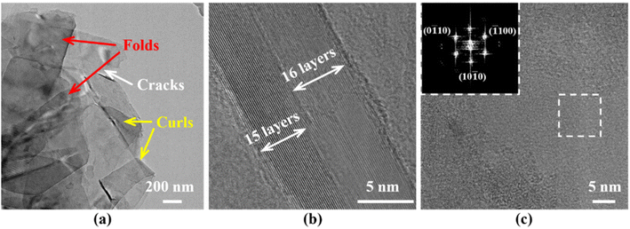
Fig. 6 shows the TEM images of G-BNNSs. In Fig. 6(a), G-BNNSs prepared by GAUCE exhibit wrinkling, cracking, and curling at the edges, which are typical features of few-layered BNNSs. These nanosheets are estimated to consist of approximately 15 to 16 layers, with an interlayer spacing of approximately 0.333 nm, consistent with the results of Lin et al.,34 as shown in Fig. 6(b). The top-left image in Fig. 6(c) presents the diffraction pattern obtained from the selected area of G-BNNSs after Fourier transform (FFT), revealing a regular hexagonal symmetry characteristic of G-BNNSs and a honeycomb lattice sp2 plane consistent with h-BN.35 This finding further confirms that BNNSs prepared by GAUCE remain crystalline, indicating that the internal structure of the BNNSs was not disrupted.
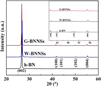
Fig. 7 shows the XRD patterns of h-BN, W-BNNSs, and G-BNNSs, presenting a series of diffraction peaks corresponding to the (002), (100), (101), (102), and (004) crystal planes. The diffraction peaks of W-BNNSs and G-BNNSs were compared with those of h-BN. No new diffraction peaks appeared, indicating that water-assisted ultrasonic exfoliation and GAUCE resulted in high-purity BNNSs and that the elemental composition of the BNNSs remained unchanged. The internal structure of the BNNSs was minimally affected by ultrasonic exfoliation, consistent with the FFT electron diffraction patterns observed in TEM analysis. Notable changes were observed in peak positions and intensities. In particular, all the characteristic peaks of G-BNNSs shifted to lower angles, mainly due to the significant reduction in thickness when few-layered BNNSs were exfoliated from bulk h-BN. Additionally, the XRD patterns in the range of 40°–60° have been magnified in the upper-right corner of Fig. 7, revealing that the intensities of the (100), (101), (102), and (004) peaks of G-BNNSs were lower than those of h-BN or W-BNNSs. Hence, GAUCE leads to a reduction in the thickness and size of G-BNNSs, consistent with the SEM, TEM, and AFM results.
5 Discussion
5.1 Process analysis of functionalized BNNSs by ultrasonic exfoliation
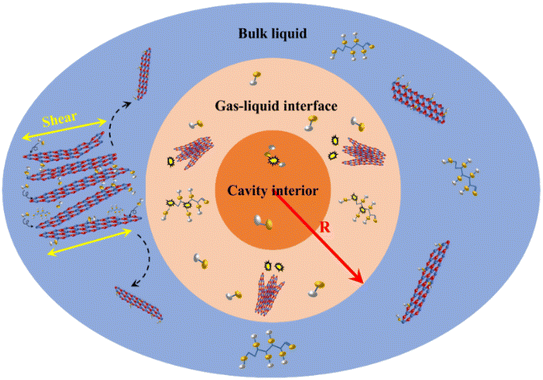
The key to preparing BNNSs is to overcome the interlayer forces of h-BN, including van der Waals forces and ‘lip–lip’ interactions. During ultrasonic exfoliation, the cyclic action of bubble collapse generated by cavitation effects exerted a transient effect on the solution. The high temperature, high pressure and microjets produced efficiently disrupted the van der Waals forces between h-BN layers. The key to achieving efficient exfoliation of h-BN and preparing high-quality BNNSs depends on utilizing the transient effect generated by bubble collapse to disrupt the ‘lip–lip’ interactions between the edge layers of h-BN. Therefore, based on the mechanical behavior and experimental research on bubble collapse, this study reveals the process mechanism of G-BNNSs obtained through GAUCE, as shown in Fig. 8.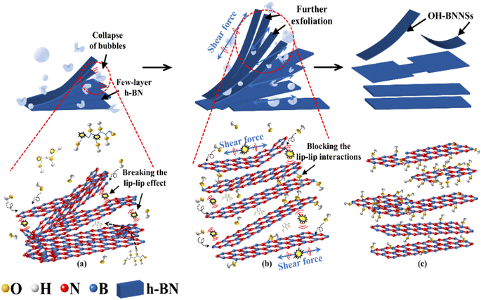 | ||
| Fig. 8 Process of G-BNNS preparation by GAUCE: (a) preliminary exfoliation of BNNSs; (b) further exfoliation of BNNSs; (c) complete exfoliation of BNNSs. | ||
During ultrasonic processing, ultrasonic vibration acts on the solution. The high temperature and pressure generated by the instantaneous collapse of bubbles primarily disrupt the ‘lip–lip’ interactions at the edges of h-BN, causing the edges to open along the weak interlayer regions, as shown in Fig. 8(a). As the extent of edge opening of h-BN increased, the shockwaves and cavitation microjets generated by the collapse of bubbles penetrating into the interlayers of h-BN further disrupted the interlayer forces, specifically van der Waals forces, leading to exfoliation of h-BN. Under strong shockwaves and localized high temperatures generated by the bubble collapse, glucose molecules and some water molecules near the bubble collapse dissociated to produce hydroxyl groups. A large number of hydroxyl groups, under the action of shockwaves, penetrated into the interlayers of h-BN, thereby increasing the distance between h-BN layers. This phenomenon not only facilitated the formation of layered BNNSs but also effectively prevented the re-aggregation of the successfully exfoliated BNNSs, as shown in Fig. 8(b). Furthermore, the continuous collapse of bubbles generated high-speed microjets, providing continuous kinetic energy to nearby water molecules, glucose molecules, and hydroxyl groups, thereby enhancing the exfoliation efficiency of the BNNSs. After the breaking of B–N bonds, the released hydroxyl groups bound to the B atoms, forming hydroxyl functional groups. BNNSs with successfully attached hydroxyl functional groups on the surface prevented re-aggregation, as shown in Fig. 8(c).
GAUCE of BNNSs can provide more hydroxyl groups compared with deionized-water-assisted ultrasonic exfoliation. The process of BNNS preparation by deionized-water-assisted ultrasonic exfoliation is shown in Fig. 9.
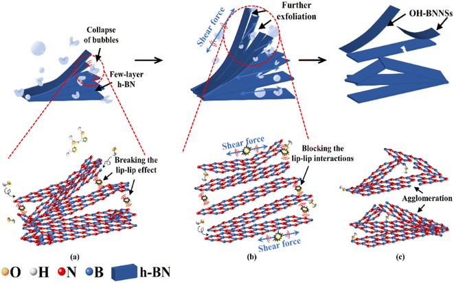 | ||
| Fig. 9 Exfoliation of W-BNNSs from the original h-BN powder: (a) preliminary exfoliation of BNNSs; (b) further exfoliation of BNNSs; (c) complete exfoliation of BNNSs. | ||
During deionized-water-assisted ultrasonic exfoliation of BNNSs, only water molecules participated in the hydroxyl group formation, resulting in few attached hydroxyl functional groups. As shown in Fig. 9(c), significant re-aggregation occurred due to the strong ‘lip–lip’ interactions and van der Waals forces at the edges of h-BN, as well as the limited expansion of interlayer distance caused by water molecules (which are much smaller than glucose molecules), leading to a lower exfoliation yield of BNNSs.
5.2 Mechanism analysis of ultrasonic exfoliation of functionalized BNNSs
Fig. 10 shows the division of the regions of bubble collapse during ultrasonic exfoliation into interface zones. As shown in Fig. 10, the orange region represents the bubble cavity region, where a small portion of water molecules undergo decomposition due to the ultra-high temperature and pressure generated during bubble collapse, resulting in highly reactive hydroxyl groups.36 These hydroxyl groups diffuse to the high temperature and pressure zones carried by the high-speed jets produced by bubble collapse. The light orange region represents the high temperature and pressure zone. In this zone, the high temperature and pressure generated by bubble collapse instantaneously disrupt the ‘lip–lip’ interactions between the edge B and N atoms of h-BN, causing the edges of h-BN to tear apart. The undecomposed glucose and water molecules enter the interlayers of h-BN, thereby expanding the interlayer distance, which is beneficial for the preparation of BNNSs. Once the edges of h-BN are opened, the high temperature and pressure resulting from bubble collapse disrupt the van der Waals forces between the internal layers of h-BN, leading to exfoliation of h-BN into thin sheets. In this zone, most glucose and water molecules decompose into hydroxyl groups, which enter the interlayers of h-BN. The hydroxyl groups bind to B atoms due to the prolonged electron deficiency on B atoms. This phenomenon forms hydroxyl functional groups, which effectively prevent re-aggregation of the upper and lower layers of h-BN caused by van der Waals forces and ‘lip–lip’ interactions. Additionally, the high-speed water jets generated by bubble collapse in this zone enhances the movement of hydroxyl groups, accelerating their attachment to BNNSs within the high temperature and pressure zone. The blue region represents the diffusion zone, where successful exfoliation of BNNSs occurs. Furthermore, hydroxyl functional groups produced by bubble collapse in the bubble cavity region or the high temperature and pressure zone can move to the diffusion zone and attach to the successfully exfoliated BNNSs.The range of bubble collapse (R), which includes the bubble cavity region and the high temperature and pressure zone, is the value that needs to be calculated in this study. The assumed range of exfoliation obtained under successful exfoliation should be compared with the actual range of bubble collapse to demonstrate the feasibility of obtaining BNNSs through ultrasonic exfoliation. If the assumed range of exfoliation due to bubble collapse is significantly larger than the actual range, then the energy generated by the bubble collapse is sufficient to achieve successful exfoliation of BNNSs.
Based on the analysis of bubble dynamics and bubble collapse kinetics in ultrasonic cavitation, Wu et al.37 defined cavitation intensity from an energy perspective and proposed an empirical formula to calculate the initial energy of a single cavitation bubble inside the cavity:
 | (1) |
According to the studies of Padilla,38 Yasui,39 and Huang,40 on the size of cavitation bubbles, Rmax is typically taken as 1 mm. The initial radius R0 is small, so it can be neglected in the calculation. P0 represents the ambient pressure and can be expressed as:
| P0 = ρgh | (2) |
By combining eqn (1) and (2), the calculated initial energy Q of a single-bubble collapse is 4.1 × 10⁻⁷ J. As the bubble cavity region and the high temperature and pressure zone are directly affected by the shock waves generated by bubble collapse, they are considered the reaction zone for BNNS exfoliation. The experimental results of ultrasonic exfoliation of BNNSs indicate that the thickness of h-BN is approximately 10 μm, while the thickness of the BNNSs is 2 nm, suggesting that h-BN consists of approximately 5000 layers of BNNSs. van der Waals forces are weaker than chemical covalent and ionic bonds and their energy is generally less than 5 kJ ml−1, so they can be neglected. Therefore, assuming that the energy provided by a single-bubble collapse is sufficient to open the edges of h-BN in the reaction zone, the following relationship holds:
| 5000NQ1 = Q | (3) |
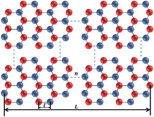
h-BN and BNNSs are composed of B and N atoms arranged alternately in a honeycomb structure through covalent bonds, as shown in Fig. 11.
In Fig. 11, n is the number of hexagonal honeycomb structures, l′ is the distance between adjacent ‘lip–lip’ interactions of B or N atoms, and L is the equivalent side length of a single-layer BNNS. Experimental results and studies on ultrasonic exfoliation42 have shown that the distance l between adjacent ‘lip–lip’ interactions of B or N atoms is approximately 2.5 Å. Therefore, the relationship between the equivalent side length L of a single-layer BNNS and the number of hexagonal honeycomb structures n can be expressed as:
 | (4) |
The relationship between the number N of B–N bonds on the edges of h-BN and the number of hexagonal honeycomb structures n is given by:
| N = 6 + 2(n − 2) | (5) |
Assuming h-BN is a cube, the equivalent side length L of a single layer BNNS can be calculated using the following formula:
 | (6) |
 | (7) |
By combining the above equations, the relationship between the equivalent side length L of a single-layer BNNS and the radius R of the reaction zone affected by a single-bubble collapse can be derived and simplified by substituting specific values:
 | (8) |
Based on eqn (3), (6) and (8), the radius R of the reaction zone affected by a single-bubble collapse is approximately 2 nm. Therefore, under the assumed conditions, the diameter range of the reaction zone is 4 nm.
The diameter of bubble collapse is within 1–4 mm. Thus, the radius of the reaction zone affected by a single-bubble collapse is larger than the assumed energy range when BNNSs are successfully exfoliated. In addition, a large number of bubbles are generated near the contact surface of the ultrasonic transducer connected to the high-frequency ultrasonic generator. The continuous high temperature and pressure generated by bubble collapse, as well as the high-speed turbulence caused by the collapse, directly act on h-BN. This transfer of energy from bubble collapse continuously spreads into the diffusion zone. Therefore, a high exfoliation yield of BNNSs can be achieved within a relatively short processing time.
5.3 Glucose-assisted ultrasonic functionalization of BNNSs
Since Chen et al.17 achieved surface hydroxyl-functionalized BNNSs using sucrose-assisted ball milling, functionalized BNNSs have shown improved dispersion in polymer matrices and significantly enhanced interfacial interactions with the polymer matrix. In the present study, FTIR spectroscopy was used to investigate the functionalization of BNNSs prepared by ultrasonic exfoliation (Fig. 12).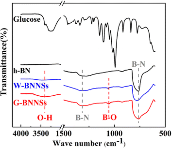 | ||
| Fig. 12 Fourier transform infrared (FTIR) spectra of glucose, h-BN, W-BNNSs, and G-BNNSs (black: glucose and h-BN; blue: W-BNNSs; red: G-BNNSs). | ||
Fig. 12 shows that h-BN, W-BNNSs, and G-BNNSs exhibit two absorption peaks at 1320 and 762 cm−1, corresponding to the stretching vibration peak of in-plane B–N bonds (approximately 1320 cm−1) and the bending vibration peak of B–N bonds (approximately 762 cm−1). This finding indicates the presence of B–N–B bonds and confirms the preservation of the honeycomb lattice sp2 structure of h-BN in BNNSs, consistent with the XRD and TEM results. Based on a comparison of the infrared spectra of G-BNNSs and glucose, no characteristic absorption peaks of glucose were observed in G-BNNSs, indicating the absence of glucose molecules on the surface of G-BNNSs after filtration and washing.
In comparison with h-BN and W-BNNSs, G-BNNSs exhibit a broader absorption peak at 762 cm−1, indicating a significant reduction in thickness.43 In addition to the stretching and bending vibration peaks of B–N bonds, the infrared spectrum of W-BNNSs also shows a slight hydroxyl peak at approximately 3399 cm−1, which could be attributed to the hydroxyl groups provided by the cleavage of deionized water during ultrasonic exfoliation and their attachment to the B atoms on the surface of W-BNNSs. In contrast, the hydroxyl peak at approximately 3399 cm−1 in G-BNNSs is broader and more pronounced, suggesting that more hydroxyl groups are provided by the simultaneous cleavage of deionized water and glucose during ultrasonic exfoliation, and more hydroxyl functional groups are attached to the B atoms on the surface of G-BNNSs. Compared with h-BN, W-BNNSs and G-BNNSs exhibit an additional new absorption peak at 1052 cm−1, which could be attributed to the symmetric stretching vibration peak of B–OH bonds.
Based on the changes in the absorption peaks in the infrared spectra, the hydroxyl functional groups are successfully attached to the B atoms on the surface of W-BNNSs and G-BNNSs, and G-BNNSs have a higher density of hydroxyl functional groups on their surface compared to W-BNNSs.
X-ray photoelectron spectroscopy (XPS) analysis was conducted on h-BN, W-BNNSs and G-BNNSs (Fig. 13). From Fig. 13, the XPS spectra of h-BN, W-BNNSs and G-BNNSs show the presence of boron (B), nitrogen (N), carbon (C), and oxygen (O). The peaks corresponding to B and N elements are significantly stronger than those corresponding to O and C elements.
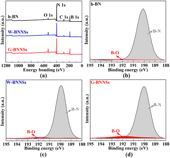 | ||
| Fig. 13 XPS spectra of h-BN, W-BNNSs and G-BNNSs: (a) XPS full spectra of h-BN, W-BNNSs and G-BNNSs; high-resolution XPS spectra of (b) h-BN; (c) W-BNNSs and (d) G-BNNSs. | ||
After peak fitting of the XPS data, the high-resolution B 1s peak scans of h-BN, W-BNNSs, and G-BNNSs show a peak centered at 190.6 eV, as shown in Fig. 13(b)–(d). This finding is consistent with the binding energy value of B atoms in h-BN reported by Dai et al.44 Additionally, in the fitted peaks of h-BN, only B–N bonds are present in the fitted peaks of W-BNNSs and G-BNNSs, where B–N and B–O bonds occur. This result indicates the attachment of hydroxyl functional groups to the surface of W-BNNSs and G-BNNSs, forming B–OH bonds consistent with FTIR analysis, as shown in Fig. 13(c) and (d).
Furthermore, more B–O bonds were observed in the high-resolution B 1s fitted peak of G-BNNSs. Hence, GAUCE provided more hydroxyl groups than deionized-water-assisted ultrasonic exfoliation. Electrons are more concentrated on the N atoms due to the difference in electronegativity between B and N atoms in BNNSs, leaving the B atoms in an electron-deficient state.44 The electron-deficient B atoms provide an opportunity to form covalent bonds with hydroxyl functional groups in the presence of negative electrons. Therefore, the free hydroxyl functional groups attach to the B atoms to balance the overall charge.
5.4 Dispersion test of functionalized BNNSs
First, 1 g of h-BN, W-BNNSs, and G-BNNSs powders were separately sealed in 10 ml of water and ethanol and left undisturbed in air for one week. The dispersion of the three powders in water and ethanol, as well as their stability, were observed and compared (Fig. 14).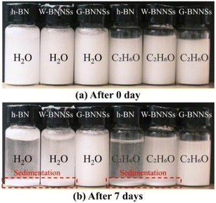 | ||
| Fig. 14 Dispersion test of h-BN, W-BNNSs, and G-BNNSs (a) initial dispersion of h-BN, W-BNNSs, and G-BNNSs; (b) dispersion of h-BN, W-BNNSs, and G-BNNSs after 7 days. | ||
As shown in Fig. 14, one week after settling, h-BN shows significant precipitation in water and ethanol due to gravity, with only a small fraction remaining suspended. By contrast, W-BNNSs exhibits improved dispersion in water and ethanol, with slight precipitation due to the presence of a small amount of hydroxyl functional groups attached to the surface. Furthermore, G-BNNSs, with a higher number of hydroxyl functional groups attached to the surface, show significantly better dispersion in water and ethanol than W-BNNSs, with almost no noticeable precipitation. This finding indicates the hydrophilicity of W-BNNSs and G-BNNSs compared with h-BN, confirming the successful attachment of hydroxyl functional groups to the surfaces of W-BNNSs and G-BNNSs. Additionally, G-BNNSs exhibit higher hydrophilicity and stability than W-BNNSs due to the combined effect of glucose and deionized water, providing more hydroxyl functional groups and attaching them to the surface of G-BNNSs.
5.5 Contact angle analysis of functionalized BNNSs
The prepared W-BNNSs and G-BNNSs powders were vacuum-dried, and the water contact angles of h-BN, W-BNNSs and G-BNNSs were measured, as shown in Fig. 15.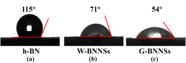 | ||
| Fig. 15 Contact angle test of h-BN, W-BNNSs, and G-BNNSs: water contact angle of (a) h-BN, (b) W-BNNSs and (c) G-BNNSs. | ||
The water contact angle of h-BN is 115°, indicating hydrophobic behavior. The water contact angle of W-BNNSs is 71°, while that of G-BNNSs is 54°. W-BNNSs and G-BNNSs have hydroxyl functional groups attached to their surfaces. They can form hydrogen bonds with water molecules, adsorb water molecules, and enhance the hydrophilicity due to the difference in electronegativity between the H and O atoms in the hydroxyl functional groups. The smaller contact angle of G-BNNSs compared with W-BNNSs is attributed to the higher number of hydroxyl functional groups attached to the surface of G-BNNSs, indicating better hydrophilicity. The AFM results indicate the presence of defects on the surfaces of W-BNNSs and G-BNNSs, which provide more attachment sites for hydroxyl functional groups. This phenomenon is also the reason for the decreased water contact angle and improved hydrophilicity of W-BNNSs and G-BNNSs.
6 Conclusions
(1) The yield of BNNSs prepared using GAUCE was 55.58%.(2) SEM, TEM, and AFM testing results showed that the lateral size of BNNSs exfoliated by GAUCE decreased, and the thickness of the flakes was 1.8 nm, indicating the successful exfoliation of bulk h-BN into few-layered BNNSs.
(3) FTIR and XPS testing results revealed that hydroxyl functional groups were grafted onto the surface of exfoliated BNNSs, and the quantity of hydroxyl functional groups increased with the addition of glucose during ultrasonic exfoliation.
(4) Contact angle and dispersibility tests demonstrated that BNNSs prepared by GAUCE reduced the contact angles and significantly improved hydrophilicity.
(5) The mechanism of ultrasonic exfoliation of high-yield BNNSs was analyzed. Bubble collapse during exfoliation provided a significant amount of energy, which broke the interlayer forces in h-BN and promoted the exfoliation of BNNSs. Most importantly, the hydroxyl groups generated from glucose decomposition were grafted onto the edges and surfaces of BNNSs, preventing the re-aggregation of nanosheets and enhancing the exfoliation yield of BNNSs.
Author contributions
Lian Zhou and Fuzhu Li conceived the research idea and planned the experiments. Bo Zhang and Ying Yan performed the synthesis, characterization and related experiments. The manuscript and revised version were written by Bo Zhang. Yun Wang and Ruitao Li revised the article and responded to the reviewers' comments. All authors have given approval to the final version of the manuscript. Fuzhu Li led the project.Conflicts of interest
There are no conflicts to declare.Acknowledgements
This study was funded by the financial support of the Six Talent Peak Selection and Training Program of Jiangsu (XNYQC-002), Jiangsu University Senior Talent Start-up Funds (16JDG038), Equipment Pre-Research Field Fund Project (80923010201), the opening foundation of the State Key Laboratory of Space Medicine Fundamentals and Application, Chinese Astronaut Research and Training Center (SMFA20K07), and National Natural Science Foundation of China (52105259).References
- A. A. Murthy, T. K. Stanev, J. D. Cain, S. Hao, T. LaMountain, S. Kim, N. Speiser, K. Watanabe, T. Taniguchi, C. Wolverton, N. P. Stern and V. P. Dravid, Intrinsic Transport in 2D Heterostructures Mediated through h-BN Tunneling Contacts, Nano Lett., 2018, 18, 2990–2998 CrossRef CAS PubMed.
- S. Singh, J. Katoch, J. Xu, C. Tan, T. Zhu, W. Amamou, J. Hone and R. Kawakami, Nanosecond spin relaxation times in single layer graphene spin valves with hexagonal boron nitride tunnel barriers, Appl. Phys. Lett., 2016, 109, 122411 CrossRef.
- A. M. Satawara, G. A. Shaikh, S. K. Gupta and P. N. Gajjar, Structural, electronic and optical properties of hexagonal boron-nitride (h-BN) monolayer: an ab initio study, Mater. Today: Proc., 2021, 47, 529–532 CAS.
- G. Gyawali, R. Adhikari, H. S. Kim, H.-B. Cho and S. W. Lee, Effect of h-BN Nanosheets Codeposition on Electrochemical Corrosion Behavior of Electrodeposited Nickel Composite Coatings, ECS Electrochem. Lett., 2012, 2, C7–C10 CrossRef.
- Z.-G. Wang, W. Liu, Y.-H. Liu, Y. Ren, Y.-P. Li, L. Zhou, J.-Z. Xu, J. Lei and Z.-M. Li, Highly thermal conductive, anisotropically heat-transferred, mechanically flexible composite film by assembly of boron nitride nanosheets for thermal management, Composites, Part B, 2020, 180, 107569 CrossRef CAS.
- J. H. Jung, C.-H. Park and J. Ihm, A Rigorous Method of Calculating Exfoliation Energies from First Principles, Nano Lett., 2018, 18, 2759–2765 CrossRef CAS PubMed.
- J. Shim, H. J. Kim, B. G. Kim, Y. S. Kim, D.-G. Kim and J.-C. Lee, 2D boron nitride nanoflakes as a multifunctional additive in gel polymer electrolytes for safe, long cycle life and high rate lithium metal batteries, Energy Environ. Sci., 2017, 10, 1911–1916 RSC.
- T. Elo, V. S. Parihar, R. Nag, A. Bera and R. Layek, Scalable synthesis of highly exfoliated, water-dispersible boron nitride nanosheets for nano-fibrillated cellulose membrane toughening, Chem. Eng. Sci., 2023, 276, 118820 CrossRef CAS.
- J. Yu, L. Qin, Y. Hao, S. Kuang, X. Bai, Y.-M. Chong, W. Zhang and E. Wang, Vertically Aligned Boron Nitride Nanosheets: Chemical Vapor Synthesis, Ultraviolet Light Emission, and Superhydrophobicity, ACS Nano, 2010, 4, 414–422 CrossRef CAS PubMed.
- A. Nadeem, M. F. Maqsood, M. A. Raza, M. T. Ilyas, M. J. Iqbal and Z. U. Rehman, Binder free boron nitride-based coatings deposited on mild steel by chemical vapour deposition: anti-corrosion performance analysis, Phys. B, 2021, 602, 412600 CrossRef CAS.
- H. J. Liu, F. Bai, E. H. Wang, T. Yang, J. H. Chen, G. Z. Zhou and X. M. Hou, Preparation and characterization of layered boron nitride nanosheets, J. Eng. Sci., 2019, 41, 1543–1549 CAS.
- K. S. Novoselov, A. K. Geim, S. V. Morozov, D. Jiang, Y. Zhang, S. V. Dubonos, I. V. Grigorieva and A. A. Firsov, Electric Field Effect in Atomically Thin Carbon Films, Science, 2004, 306, 666–669 CrossRef CAS PubMed.
- X. Chen, J. F. Dobson and C. L. Raston, Vortex fluidic exfoliation of graphite and boron nitride, Chem. Commun., 2012, 48, 3703 RSC.
- C. Zhi, Y. Bando, C. Tang, H. Kuwahara and D. Golberg, Large-Scale Fabrication of Boron Nitride Nanosheets and Their Utilization in Polymeric Composites with Improved Thermal and Mechanical Properties, Adv. Mater., 2009, 21, 2889–2893 CrossRef CAS.
- D. Pacilé, J. C. Meyer, Ç. Ö. Girit and A. Zettl, The two-dimensional phase of boron nitride: few-atomic-layer sheets and suspended membranes, Appl. Phys. Lett., 2008, 92, 133107, DOI:10.1063/1.2903702.
- Z. Wang, X. Yan, Q. Hou, Y. Liu, X. Zeng, Y. Kang, W. Zhao, X. Li, S. Yuan, R. Qiu, M. H. Uddin, R. Wang, Y. Xia, M. Jian, Y. Kang, L. Gao, S. Liang, J. Z. Liu, H. Wang and X. Zhang, Scalable high yield exfoliation for monolayer nanosheets, Nat. Commun., 2023, 14, 236 CrossRef CAS PubMed.
- S. Chen, R. Xu, J. Liu, X. Zou, L. Qiu, F. Kang, B. Liu and H.-M. Cheng, Simultaneous Production and Functionalization of Boron Nitride Nanosheets by Sugar-Assisted Mechanochemical Exfoliation, Adv. Mater., 2019, 31, 1804810 CrossRef PubMed.
- H. Soyama and A. M. Korsunsky, A critical comparative review of cavitation peening and other surface peening methods, J. Mater. Process. Technol., 2022, 305, 117586 CrossRef CAS.
- L. Wu, K. Wu, D. Liu, R. Huang, J. Huo, F. Chen and Q. Fu, Largely enhanced energy storage density of poly(vinylidene fluoride) nanocomposites based on surface hydroxylation of boron nitride nanosheets, J. Mater. Chem. A, 2018, 6, 7573–7584 RSC.
- Y. Lin, T. V. Williams, T.-B. Xu, W. Cao, H. E. Elsayed-Ali and J. W. Connell, Aqueous Dispersions of Few-Layered and Monolayered Hexagonal Boron Nitride Nanosheets from Sonication-Assisted Hydrolysis: Critical Role of Water, J. Phys. Chem. C, 2011, 115, 2679–2685 CrossRef CAS.
- J. Ding, H. Zhao, Q. Wang, W. Peng and H. Yu, Ultrahigh performance heat spreader based on gas-liquid exfoliation boron nitride nanosheets, Nanotechnology, 2017, 28, 475602 CrossRef PubMed.
- L. An, Y. Yu, Q. Cai, S. Mateti, L. H. Li and Y. I. Chen, Hexagonal boron nitride nanosheets: preparation, heat transport property and application as thermally conductive fillers, Prog. Mater. Sci., 2023, 138, 101154 CrossRef CAS.
- Y. Li, T. Huang, M. Chen and L. Wu, Simultaneous exfoliation and functionalization of large-sized boron nitride nanosheets for enhanced thermal conductivity of polymer composite film, Chem. Eng. J., 2022, 442, 136237 CrossRef CAS.
- G. R. Bhimanapati, D. Kozuch and J. A. Robinson, Large-scale synthesis and functionalization of hexagonal boron nitride nanosheets, Nanoscale, 2014, 6, 11671–11675 RSC.
- G. Ledoux, J. Gong, F. Huisken, O. Guillois and C. Reynaud, Photoluminescence of size-separated silicon nanocrystals: confirmation of quantum confinement, Appl. Phys. Lett., 2002, 80, 4834–4836 CrossRef CAS.
- S. E, Z. Zhu, L. Xie, Z. Li, R. Geng, T. Li, C. Li, W. Lu and Y. Yao, An integrated strategy towards the high-yield fabrication of soluble boron nitride nanosheets, Chem. Eng. J., 2019, 360, 1407–1415 CrossRef CAS.
- L. Bertolla, I. Šulák, J. Buršík, I. Dlouhý, J. Smilek, P. Mácová and J. Holas, Exfoliation of hexagonal boron nitride nanosheets in low-modulus concentrated alkali silicate pastes, Mater. Lett., 2021, 292, 129551 CrossRef CAS.
- G. Chen, H. Weng, Z. Wu, Y. Chen, P. Zhang, G. Ye and M. Lin, High-yield production of monolayer boron nitride nanosheets by cationic-surfactant-assisted solvothermal exfoliation for the ultrafast and selective separation of U(VI) from lanthanides, Sep. Purif. Technol., 2021, 278, 119645 CrossRef.
- F. Goni, A. Chemelli and F. Uhlig, High-Yield Production of Selected 2D Materials by Understanding Their Sonication-Assisted Liquid-Phase Exfoliation, Nanomaterials, 2021, 11, 3253 CrossRef CAS PubMed.
- W. Sun, Y. Meng, Q. Fu, F. Wang, G. Wang, W. Gao, X. Huang and F. Lu, High-Yield Production of Boron Nitride Nanosheets and Its Uses as a Catalyst Support for Hydrogenation of Nitroaromatics, ACS Appl. Mater. Interfaces, 2016, 8, 9881–9888 CrossRef CAS PubMed.
- D. G. Ortiz, C. Pochat-Bohatier, J. Cambedouzou, M. Bechelany and P. Miele, Exfoliation of Hexagonal Boron Nitride (h-BN) in Liquide Phase by Ion Intercalation, Nanomaterials, 2018, 8, 716 CrossRef PubMed.
- F. Yuan, W. Jiao, F. Yang, W. Liu, J. Liu, Z. Xu and R. Wang, Scalable exfoliation for large-size boron nitride nanosheets by low temperature thermal expansion-assisted ultrasonic exfoliation, J. Mater. Chem. C, 2017, 5, 6359–6368 RSC.
- T. Wang, M. Wang, L. Fu, Z. Duan, Y. Chen, X. Hou, Y. Wu, S. Li, L. Guo, R. Kang, N. Jiang and J. Yu, Enhanced Thermal Conductivity of Polyimide Composites with Boron Nitride Nanosheets, Sci. Rep., 2018, 8, 1557 CrossRef PubMed.
- Y. Lin and J. W. Connell, Advances in 2D boron nitride nanostructures: nanosheets, nanoribbons, nanomeshes, and hybrids with graphene, Nanoscale, 2012, 4, 6908 RSC.
- L. Cao, J. Wang, J. Dong, X. Zhao, H.-B. Li and Q. Zhang, Preparation of highly thermally conductive and electrically insulating PI/BNNSs nanocomposites by hot-pressing self-assembled PI/BNNSs microspheres, Composites, Part B, 2020, 188, 107882 CrossRef CAS.
- M. Pirsaheb and N. Moradi, Sonochemical degradation of pesticides in aqueous solution: investigation on the influence of operating parameters and degradation pathway – a systematic review, RSC Adv., 2020, 10, 7396–7423 RSC.
- P. Wu, L. Bai and W. Lin, On the Definition of Cavitation Intensity, Ultrason. Sonochem., 2018, 49, 89 CrossRef CAS PubMed.
- J. P. Padilla-Martinez, D. Banks, J. C. Ramirez-San-Juan, G. Aguilar and R. Ramos-Garcia, in Liquid Jet Generated by Thermocavitation Bubbles within a Droplet, ed. A. Heisterkamp, P. R. Herman, M. Meunier and S. Nolte, San Francisco, California, USA, 2013, p. 86111J Search PubMed.
- K. Yasui, Effects of thermal conduction on bubble dynamics near the sonoluminescence threshold, J. Acoust. Soc. Am., 1995, 98, 2772–2782 CrossRef.
- H. Huang, L. Qin, H. Tang, D. Shu, W. Yan, B. Sun and J. Mi, Ultrasound cavitation induced nucleation in metal solidification: an analytical model and validation by real-time experiments, Ultrason. Sonochem., 2021, 80, 105832 CrossRef CAS PubMed.
- M. S. Plesset and R. B. Chapman, Collapse of an initially spherical vapour cavity in the neighbourhood of a solid boundary, J. Fluid Mech., 1971, 47, 283–290 CrossRef.
- M. Li, M. Wang, X. Hou, Z. Zhan, H. Wang, H. Fu, C.-T. Lin, L. Fu, N. Jiang and J. Yu, Highly thermal conductive and electrical insulating polymer composites with boron nitride, Composites, Part B, 2020, 184, 107746 CrossRef CAS.
- X. Wang, Y. Yang, G. Jiang, Z. Yuan and S. Yuan, A facile synthesis of boron nitride nanosheets and their potential application in dye adsorption, Diamond Relat. Mater., 2018, 81, 89–95 CrossRef CAS.
- X. J. Dai, Y. Chen, Z. Chen, P. R. Lamb, L. H. Li, J. Du Plessis, D. G. McCulloch and X. Wang, Controlled surface modification of boron nitride nanotubes, Nanotechnology, 2011, 22, 245301 CrossRef PubMed.
| This journal is © The Royal Society of Chemistry 2023 |

