 Open Access Article
Defect engineering and atomic doping of porous Co-Ni2P nanosheet arrays for boosting electrocatalytic oxygen evolution†
Qiangqiang
Wang
a,
Hongmin
Ma
 a,
Xiang
Ren
 a,
Xu
Sun
a,
Xuejing
Liu
a,
Dan
Wu
a,
Xu
Sun
a,
Xuejing
Liu
a,
Dan
Wu
 *a and
Qin
Wei
 *ab
*ab
aSchool of Chemistry and Chemical Engineering, University of Jinan, Jinan 250022, P. R. China. E-mail: wudan791108@163.com; sdjndxwq@163.com
bDepartment of Chemistry, Sungkyunkwan University, Suwon, 16419, Republic of Korea
First published on 2nd June 2023
Abstract
Electrochemical hydrogen production by splitting water is mainly limited to the oxygen evolution reaction (OER), which requires high energy consumption. The design of an efficient and stable electrochemical catalyst is the key to solving this problem. Here, a three-dimensional porous Co-doped Ni2P nanosheet (Co-Ni2P/NF-corr) was synthesized by simple hydrothermal, acid leaching and phosphating processes successively. Excitingly, the current density of Co-Ni2P-corr in 1 M KOH solution can reach 50 mA cm−2 with only 267 mV overpotential. Moreover, the Tafel slope is very small, only 64 mV dec−1. In addition, the stability test shows that it can work stably at 50 mA cm−2 current density for at least 48 h.
Introduction
With the rapid development of science and technology, the sharp decline of fossil fuel reserves and the serious damage of human activities to the ecological environment, it is vital to find clean energy. As a zero-carbon footprint product with high energy density, hydrogen has become the representative of new energy and the “future star” of clean energy.1–4 Electrochemical splitting of water is the most economical, efficient and sustainable hydrogen production method at present. However, the hydrolysis reaction is mainly limited by the high energy consumption of the anodic oxygen evolution reaction (OER) process. In commercial applications, the OER process mainly depends on precious metal catalysts, such as IrO2 and RuO2. However, their high price and scarcity limit their development prospects. Transition metal compounds have been deeply explored to find suitable substitutes for noble metal catalysts.5–11Over the past few years, transition metal phosphides,12 sulfides,13 nitrides,14 layered double hydroxides15etc. have made considerable progress as OER catalysts. Among them, transition metal phosphides (TMPs), such as NixPy,16,17 CoxPy,18,19 and FexPy,20,21 have become the most powerful candidates for noble metal catalysts because of their many advantages. On the one hand, due to the high electronegativity of the P atom, the electron cloud of the metal atom will be biased towards the P atom when the metal atom binds with the P atom, which makes the P atom an excellent proton acceptor. On the other hand, TMPs can be in situ oxidized to metal hydroxide oxides, oxides or phosphates at oxidation potential. Such oxidation intermediates have high catalytic activity and are considered to be the inherent catalytic active sites of the OER.22–26 It is worth noting that the OER performance of bimetallic phosphides is much higher than that of monometallic phosphides, which is due to the synergistic effect between metal atoms. The addition of a small amount of metal cations can be used as a promoter of phosphide activity; they can change the electronic structure of the main element, thus improving its intrinsic activity.27,28 Yingjie Li et al. designed and synthesized an iron-doped Ni2P nano-catalyst, which effectively improved the OER activity of the catalyst by controlling the amount of Fe incorporation.29 Unfortunately, due to the solid nanostructure of TMPs, the interaction between the internal active site and the reactant is largely prevented, resulting in a slow catalytic process. Moreover, this structure is not conducive to the analysis of the gas generated, which will inevitably cause some physical losses to the catalyst.30 Interface engineering can effectively improve the activity of the OERcatalyst; the porous structure can effectively improve the specific surface area of the catalyst, expose a large number of active sites, and provide more diffusion channels for gas generation.31,32 Jakkid Sanetuntikul and his collaborators designed a hierarchical porous nanomaterial co-doped with cobalt and nitrogen. Due to its large specific surface area, the density of the active site of the catalyst is greatly improved, showing good electrocatalytic activity and long-term stability.33 In addition, Chen et al. synthesized a kind of porous commercial MnCO3 using hydrochloric acid corrosion, proving that acid etching nanomaterials can also form porous structures, thus increasing the specific surface area of the material and accelerating charge transfer, which is of great significance for improving the performance of the catalyst.34
Based on the above research inspiration, in this paper, we have synthesized a porous Co-Ni2P/NF-corr nanosheet catalyst for electrochemical OER processes. The Co-Ni(OH)F nanosheets distributed vertically on NF provide a large enough surface area for H2SO4 corrosion. After the etching of H2SO4, the tiny pores formed by the nanosheets greatly increased the number of sites. Finally, the intrinsic activity of the catalyst was further increased by phosphating at low temperature. This porous Co-Ni2P/NF-corr nanosheet catalyst prepared by atomic doping and structural regulation shows excellent OER performance. Only 267 mV overpotential is required in 1 M KOH solution to achieve a current density of 50 mA cm−2. It can work stably at this current density for 48 h. This research provides a new way to solve the problems of the slow electron transfer rate and poor long-term stability of traditional transition metal-based catalysts.
Experimental
Preparation of Co-Ni(OH)F/NF
First, foamed nickel was cleaned with hydrochloric acid, alcohol, and ultrapure water to remove the nickel oxide layer and oil stain on the surface. Secondly, nickel nitrate(II) hexahydrate (2.72 mmol), cobalt nitrate(II) hexahydrate (0.272 mmol), urea (10 mmol), and NH4F (5 mmol) dissolved in 40 mL ultrapure water were stirred at room temperature for 30 min to form a green uniformly mixed solution. Finally, nickel foam and green solution were transferred together to a 50 mL Teflon-lined stainless steel autoclave, reacted for 6 h in an oven at 120 °C, cooled naturally to room temperature, washed with deionized water to remove green precipitates on the surface, and dried for 12 h in a vacuum drying oven at 60 °C.Preparation of Co-Ni(OH)F/NF-corr
The prepared Co-Ni(OH)F/NF nanosheets were soaked in 30 mL of 5 M H2SO4 for 15 s and then taken out quickly. Ultrapure water was used to wash away the residual sulfuric acid and sulphate on the surface, and they were placed into a 60 °C vacuum drying oven for drying to obtain Co-Ni(OH)F/NF-corr.Preparation of Co-Ni2P/NF-corr
500 mg of sodium hypophosphite was weighed and placed in the upstream magnetic boat of a tube furnace. In contrast, Co-Ni(OH)F/NF-corr was placed under the lower Teflon line, heated to 300 °C at a heating rate of 2 °C min−1, and maintained for 120 min. After the system is naturally cooled to room temperature, the sample Co-Ni2P/NF-corr is collected.In addition, a similar method is used to change the soaking time of the sample in sulfuric acid. The sample soaked for 10 s is named Co-Ni2P/NF-corr-10 s, and the sample soaked for 20 s is named Co-Ni2P/NF-corr-20 s.
Results and discussion
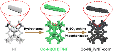
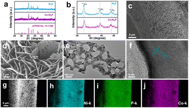
Scheme 1 is the preparation process diagram of the porous Co-Ni2P/NF-corr nanosheets; the process is performed in three steps. First, a simple hydrothermal method is used to synthesize the Co-Ni(OH)F/NF precursor on the NF substrate with a thickness of 1 mm. Then, after soaking in 5 M H2SO4 and low-temperature phosphating, a kind of Co-Ni2P/NF-corr nanosheet with a microporous structure is obtained.The structure and composition of the samples were studied by X-ray diffraction (XRD). Since NF has a certain influence on the XRD pattern, ultrasonic treatment should be carried out on the sample before the XRD test to eliminate the influence of NF. It can be seen in Fig. 1a that the five diffraction peaks at 40.7°, 44.6°, 47.3°, 54.2°, and 55.0° can be attributed to Ni2P (74-1385),34 which correspond to the (111), (201), (210), (300) and (211) crystal planes respectively. In addition, it can be found that the diffraction peaks of Co-Ni2P shift 0.11°, 0.20°, and 0.14° to the right at 40.7°, 44.6°, and 47.3° respectively (Fig. 1b), which indicates that the addition of Co will cause slight changes in the lattice of Ni2P. Before OER performance research on the Co-Ni2P/NF-corr catalyst, scanning electron microscopy (SEM) and transmission electron microscopy (TEM) were used to characterize the structure and morphology of the samples. As can be seen in Fig. S1a,† the untreated NF has a smooth surface and a large surface area, which provide a strong guarantee for the growth of nanomaterials. After hydrothermal synthesis, Co-Ni(OH)F/NF nanosheets grow vertically and crisscross on the NF substrate (Fig. 1c). Fig. S1b† shows the SEM spectrum of Co-Ni(OH)F/NF-corr nanosheets. It can be seen that after immersion in H2SO4, the surface of the nanosheets appears to have dense holes. Fig. 1d shows the SEM spectrum of Co-Ni2P/NF-corr nanosheets; the pore structure of the nanosheets remains unchanged after low temperature phosphating. The inset shows the Co-Ni2P/NF-corr images of different multiples. In addition, after the Co-Ni(OH)F/NF nanosheets were soaked in 5 M H2SO4 for 10 s, the edges of the nanosheets were slightly corroded, some holes appeared, and the surface changed slightly. However, when the immersion time reaches 20 s, the corrosion of the nanosheet is relatively serious, with some large holes and some cracks (Fig. S2†). Therefore, H2SO4-soaked samples for 15 s are selected for subsequent analysis. As shown in Fig. 1e, TEM images further confirmed the porous structure of Co-Ni2P/NF-corr nanosheets. In addition, lattice fringes spaced at 0.222 nm, corresponding to the (111) crystal plane of Ni2P, can be clearly seen in the HRTEM image (Fig. 1f). Compared with that of smooth Co-Ni2P/NF nanosheets (Fig. S3†), the surface of the Co-Ni2P/NF-corr nanosheets was etched with H2SO4 to form dense holes, which increased the active sites involved in the electrochemical reaction.
The specific surface area, pore size and pore size distribution of the sample were obtained by the Brunauer–Emmett–Teller (BET) test. As shown in Fig. S4a,† Co-Ni2P/NF-corr (209.1332 m2 g−1) has a larger surface area than Co-Ni2P/NF (32.8813 m2 g−1). When the catalyst participates in the reaction, it can better come into contact with the solution, indicating that Co-Ni2P/NF-corr may have a larger active surface area. Co-Ni2P/NF-corr has a pore size of about 6.34 nm (Fig. S4b†), which provides an extremely large active area and a short electron transport channel for the catalytic process and is very conducive to the diffusion of generated gases. In addition, energy-dispersive X-ray spectroscopy (EDX) shows that Ni, Co, and P coexist (Fig. S5†). The SEM and elemental mapping images show that Ni, Co, and P elements are uniformly dispersed along the NF surface (Fig. 1g–j).
X-ray photoelectron spectroscopy (XPS) was used to further reveal the composition and chemical state of Co-Ni2P/NF corr. Full spectrum scanning further proves the existence of Ni, Co and P (Fig. 2a), which is highly consistent with the elemental mapping results. The high-resolution XPS image of Ni 2p in Co-Ni2P/NF-corr (Fig. 2b) can be divided into two main peaks. The binding energies (BEs) at 853.40 eV (NiIII) and 856.10 eV (NiII) correspond to Ni 2p3/2, and the satellite peak (“Sat.” for short) appears at 860.10 eV; the BEs at 870.71 eV (NiIII) and 872.9 eV (NiII) correspond to Ni 2p1/2, showing Sat. at 878.24 eV.35 In Fig. 2d, it can be seen that the BE of the Ni atom is slightly increased by 0.3 eV at 853.1 eV and 870.4 eV, indicating that the incorporation of Co will change the central charge of Ni and eventually lead to an increase in the binding energy of Ni. As for the P 2p spectrum (Fig. 2c), it can be seen that the P element can fit three BEs 129.72, 130.83 and 131.82 eV, corresponding to P 2p3/2, P 2p1/2 and P–O bonds respectively, wherein the P–O bond is the phosphate formed due to the oxidation of surface phosphide.36 The weak signal of Co 2p suggests the presence of trace cobalt (Fig. S6†). In addition, we tested the content of Co through inductively coupled plasma-mass spectrometry (ICP-MS), and the result showed that the ratio of Co to the Ni atom was 0.085![[thin space (1/6-em)]](https://www.rsc.org/images/entities/char_2009.gif) :
:![[thin space (1/6-em)]](https://www.rsc.org/images/entities/char_2009.gif) 1. Combined with the above results, it can be determined that Co-Ni2P/NF-corr nanosheets were successfully prepared.
1. Combined with the above results, it can be determined that Co-Ni2P/NF-corr nanosheets were successfully prepared.
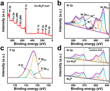 | ||
| Fig. 2 (a) XPS survey spectrum of Co-Ni2P/NF-corr; high-resolution XPS spectra of Ni 2p (b) and P 2p (c) in Co-Ni2P/NF-corr; (d) Ni 2p XPS spectra in Co-Ni2P/NF-corr and Co-Ni2P/NF. | ||
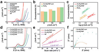
A three-electrode system is used to evaluate the electrochemical OER performance of materials. Fig. 3a shows the linear scanning curve (LSV) each material during the experiment. It can be seen that bare NF has little effect on the OER process, but its unique metal skeleton can provide good conditions for the growth of nanomaterials. With Ni(OH)F/NF attached to the NF surface, 383 mV overpotential is required to achieve a current density of 50 mA cm−2 (for comparison, the subsequent current density is subject to 50 mA cm−2). After low-temperature phosphating, the overpotential of Ni2P/NF decreases to 337 mV, indicating that phosphating has played a certain role in promoting the catalytic process. With the incorporation of metal Co, the measured overpotential of Co-Ni2P/NF is 296 mV, which is significantly lower than that of Ni2P/NF. Excitingly, Co-Ni2P/NF-corr obtained through H2SO4 corrosion can achieve a current density of 50 mA cm−2 with only 267 mV overpotential, which is close to 260 mV of RuO2 with a good catalytic performance at present. At the same time, the catalytic performance of Co-Ni2P/NF-corr is better than that of other catalysts that have been reported so far (Table S1†). Moreover, its performance is better than RuO2 after the current density reaches 450 mA cm−2 (Fig. 3b). This result further confirmed that the synergistic effect of Co and Ni and the pore structure formed by H2SO4 etching greatly enhanced the OER performance of Ni2P.
In order to verify the influence of H2SO4 corrosion on catalytic activity, only the soaking time of H2SO4 was changed to obtain three different electrode materials. From the polarization curve, it can be clearly seen that the catalytic activity of the catalyst reaches its peak when soaked for 15 s (Fig. 3d). Therefore, Co-Ni2P/NF-corr-15 s is selected for subsequent electrochemical research. The LSV curves of each material show that the Tafel slopes of Co-Ni2P/NF, Co-Ni2P/NF-corr, and RuO2 are 125, 64, and 75 mV dec−1 respectively (Fig. 3c), indicating that Co-Ni2P/NF-corr has the best reaction kinetics.
Another benchmark of catalyst performance is electrochemical active area (ECSA). The value of ECSA is positively correlated with the electrochemical double-layer capacitance (Cdl).37 The Cdl can be obtained by measuring the relationship between different scanning speeds and current density. Fig. S7a–c† shows the cyclic voltammetry (CV) curve without oxidation and reduction of Co-Ni2P/NF-corr, Co-Ni2P/NF and NF at different scanning speeds. Fig. 3e shows that the Cdl values of NF, Co-Ni2P/NF and Co-Ni2P/NF-corr are 1.74, 3.52 and 19.79 mF cm−2, respectively. On the premise that the geometric area is the same as 0.25 cm2, the ECSA area of NF is calculated to be 2.16 cm2 according to the CV curve (Fig. S8†). Based on the linear relationship, the value of ECSA of Co-Ni2P/NF and Co-Ni2P/NF-corr can be calculated to be 4.37 and 24.56 cm2 respectively. These results indicate that the formation of a porous structure exposes a large number of active sites, thus improving the catalytic activity of Co-Ni2P/NF-corr. At the same time, the Nyquist diagram (Fig. 3f) confirms that the charge transfer impedance of Co-Ni2P/NF-corr is much smaller than that of Co-Ni2P/NF, indicating that the former has a faster charge transfer speed. In addition, the electron utilization rate of Co-Ni2P/NF-corr in 1 M KOH solution was measured using a simple gas collection device. The Faraday efficiency (FE) of the catalyst was measured by comparing the theoretical gas production with the actual gas production under the same conditions. Fig. S9† shows that the FE of Co-Ni2P/NF-corr is close to 100%, manifesting that the catalyst has strong electron transfer ability and high electrode reaction efficiency.
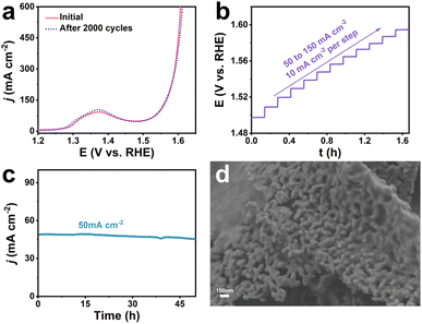
The stability of the catalyst is an important parameter to measure its practical application value. As can be seen from Fig. 4a, the LSV curve of Co-Ni2P/NF-corr showed negligible changes after 2000 CV cycles, showing excellent mechanical stability. Fig. 4b shows the multi-step timing current curve of Co-Ni2P/NF-corr (the current density gradually increases from 50 mA cm−2 to 160 mA cm−2, increasing by 10 mA cm−2 every 500 s). The potential reached 1.49 V vs. RHE at the beginning and remained stable for the next 500 s. The other steps showed similar results, further proving that Co-Ni2P/NF-corr has good corrosion resistance and mass transfer rate. The long-term stability of Co-Ni2P/NF-corr was tested at a potential of 1.49 V (Fig. 4c). It can be seen that the catalyst could work stably for 50 h at a current density of 50 mA cm−2, and the ampere density did not decrease significantly, indicating that Co-Ni2P/NF-corr showed very stable catalytic performance. Fig. 4d shows the SEM image of Co-Ni2P/NF-corr after participating in the OER process. It can be seen that the catalyst still maintains its original porous nanosheet structure. Further analysis by XPS showed that the valence states and electronic structures of Co and Ni in the Co-Ni2P/NF-corr after the reaction did not change (Fig. S10a–d†). In addition, no new diffraction peaks appeared in the XRD pattern of the catalyst after the OER process (Fig. S11†). The above results indicate that Co-Ni2P/NF-corr exhibits good stability in an alkaline solution.
Conclusions
In conclusion, a porous Co-Ni2P/NF-corr nanosheet has been synthesized on a NF substrate loop through hydrothermal synthesis, H2SO4 immersion, and phosphating at a low temperature. This porous nanosheet structure has been shown to be an efficient and stable OER catalyst under alkaline conditions. By applying Co-Ni2P/NF-corr to the OER process, we find that only an overpotential of 267 mV is needed to achieve a current density of 50 mA cm−2, with a Tafel slope of only 64 mV dec−1. The excellent performance of the catalyst is mainly due to the bimetallic synergism and the special porous structure: (1) in Co–Ni bimetallic phosphide, the uniform distribution of relevant active sites enhanced the tendency of O–O bond formation and improved the intrinsic activity of the catalyst; (2) after etching with H2SO4, the nanosheet perforated and a lot of active angles and edge sites appeared, which increased the density of active sites to a certain extent. This three-dimensional porous nanosheet structure can not only provide a large active area and a short electron transport channel, but is also very conducive to the diffusion of generated gases. In addition, Co-Ni2P/NF-corr showed good electrochemical stability; the catalytic activity did not decrease significantly after working for 48 h. This study provides a nano-catalyst with a porous structure for the OER process in a strong alkaline environment and provides a feasible idea for other OER electrocatalysts.Conflicts of interest
The authors declare that they have no known competing financial interests or personal relationships that could have appeared to influence the work reported in this paper.Acknowledgements
This work was supported by the Young Taishan Scholars Program of Shandong Province (tsqn201909124), the Project of “20 items of University” of Jinan (2019GXRC018) and the Talent Introduction and Training Program for Youth Innovation Teams in Colleges and Universities of Shandong Province. All of the authors express their sincere thanks.Notes and references
- J. Li and G. Zheng, Adv. Sci., 2017, 4, 1600380 CrossRef PubMed.
- J. Wang, W. Cui, Q. Liu, Z. Xing, A. M. Asiri and X. Sun, Adv. Mater., 2016, 28, 215–230 CrossRef CAS PubMed.
- I. Staffell, D. Scamman, A. Velazquez Abad, P. Balcombe, P. E. Dodds, P. Ekins, N. Shah and K. R. Ward, Energy Environ. Sci., 2019, 12, 463–491 RSC.
- T. Huang, K. Xu, N. Jia, L. Yang, H. Liu, J. Zhu and Q. Yan, Adv. Mater., 2022, 35, 2205206 CrossRef PubMed.
- F. Diao, W. Huang, G. Ctistis, H. Wackerbarth, Y. Yang, P. Si, J. Zhang, X. Xiao and C. Engelbrekt, ACS Appl. Mater. Interfaces, 2021, 13, 23702–23713 CrossRef CAS PubMed.
- J. E. Lee, K. J. Jeon, P. L. Show, I. H. Lee, S. C. Jung, Y. J. Choi, G. H. Rhee, K. Y. A. Lin and Y. K. Park, Fuel, 2022, 308, 122048 CrossRef CAS.
- S. Wang, P. Yang, X. Sun, H. Xing, J. Hu, P. Chen, Z. Cui, W. Zhu and Z. Ma, Appl. Catal., B, 2021, 297, 120386 CrossRef CAS.
- Y. Wang, G. Qian, Q. Xu, H. Zhang, F. Shen, L. Luo and S. Yin, Appl. Catal., B, 2021, 286, 119881 CrossRef CAS.
- X. Tao, S. Luo, C. Tian, Y. Qing, X. Lu, N. Yan and Y. Wu, ACS Sustainable Chem. Eng., 2020, 8, 1859–1867 CrossRef CAS.
- L. Wu, L. Yu, F. Zhang, B. McElhenny, D. Luo, A. Karim, S. Chen and Z. Ren, Adv. Funct. Mater., 2020, 31, 2006484 CrossRef.
- C. Wang, C. Li, J. Liu and C. Guo, Mater. Rep.: Energy, 2021, 1, 100006 CAS.
- L. Liu, N. Li, J. Han, K. Yao and H. Liang, Int. J. Miner., Metall. Mater., 2022, 29, 503–512 CrossRef CAS.
- S. Jin, ACS Energy Lett., 2017, 2, 1937–1938 CrossRef CAS.
- F. Yang, D. Hegh, D. Song, J. Zhang, K. A. S. Usman, C. Liu, Z. Wang, W. Ma, W. Yang, S. Qin and J. M. Razal, Mater. Rep.: Energy, 2022, 2, 100079 CAS.
- M. Xiao, C. Zhang, P. Wang, W. Zeng, J. Zhu, Y. Li, W. Peng, Q. Liu, H. Xu, Y. Zhao, H. Li, L. Chen, J. Yu and S. Mu, Mater. Today Phys., 2022, 24, 100684 CrossRef CAS.
- L. An, L. Bai, Y. Sun, L. Tang, L. Ma, J. Guo, Q. Liu and X. Zhang, Appl. Surf. Sci., 2020, 520, 146363 CrossRef CAS.
- W. Z. Zhang, G. Y. Chen, J. Zhao, J. C. Liang, L. F. Sun, G. F. Liu, B. W. Ji, X. Y. Yan and J. R. Zhang, J. Colloid Interface Sci., 2020, 561, 638–646 CrossRef CAS PubMed.
- M. Cong, D. Sun, L. Zhang and X. Ding, Chin. J. Catal., 2020, 41, 242–248 CrossRef CAS.
- Z. H. Xue, H. Su, Q. Y. Yu, B. Zhang, H. H. Wang, X. H. Li and J. S. Chen, Adv. Energy Mater., 2017, 7, 1602355 CrossRef.
- Y. Wang, Z. Chen, H. Wu, F. Xiao, E. Cao, S. Du, Y. Wu and Z. Ren, ACS Sustainable Chem. Eng., 2018, 6, 15727–15736 CrossRef CAS.
- J. Huang, Y. Su, Y. Zhang, W. Wu, C. Wu, Y. Sun, R. Lu, G. Zou, Y. Li and J. Xiong, J. Mater. Chem. A, 2018, 6, 9467–9472 RSC.
- C. Du, L. Yang, F. Yang, G. Cheng and W. Luo, ACS Catal., 2017, 7, 4131–4137 CrossRef CAS.
- B. Nourmohammadi Khiarak, M. Golmohammad, M. M. Shahraki and A. Simchi, J. Alloys Compd., 2021, 875, 160049 CrossRef CAS.
- L.-M. Cao, J. Zhang, L. W. Ding, Z. Y. Du and C. T. He, J. Energy Chem., 2022, 68, 494–520 CrossRef CAS.
- Y. Lu, X. Zheng, Y. Liu, J. Zhu, D. Li and D. Jiang, Inorg. Chem., 2022, 61, 8328–8338 CrossRef CAS PubMed.
- H. Bai, D. Chen, Q. Ma, R. Qin, H. Xu, Y. Zhao, J. Chen and S. Mu, Electrochem. Energy Rev., 2022, 5, 24 CrossRef CAS.
- Y. Lu, C. Liu, S. Xu, Y. Liu, D. Jiang and J. Zhu, Appl. Surf. Sci., 2021, 565, 150537 CrossRef CAS.
- H. Xu, J. Zhu, P. Wang, D. Chen, C. Zhang, M. Xiao, Q. Ma, H. Bai, R. Qin, J. Ma and S. Mu, J. Mater. Chem. A, 2021, 9, 24677–24685 RSC.
- Y. Li, H. Zhang, M. Jiang, Q. Zhang, P. He and X. Sun, Adv. Funct. Mater., 2017, 27, 1702513 CrossRef.
- S. Sun, M. Zheng, P. Cheng, F. Wu and L. Xu, J. Colloid Interface Sci., 2022, 626, 515–523 CrossRef CAS PubMed.
- H. Xia, Z. Huang, C. Lv and C. Zhang, ACS Catal., 2017, 7, 8205–8213 CrossRef CAS.
- J. Kim, X. Chen, P. C. Shih and H. Yang, ACS Sustainable Chem. Eng., 2017, 5, 10910–10917 CrossRef CAS.
- J. Sanetuntikul, S. Hyun, P. Ganesan and S. Shanmugam, J. Mater. Chem. A, 2018, 6, 24078–24085 RSC.
- L. Chen, M. Han, T. Song, L. Liu, X. Zheng, W. He, B. Long, X. Wang and X. Wu, J. Alloys Compd., 2023, 952, 170049 CrossRef CAS.
- X. Sun, P. Yang, S. Wang, J. Hu, P. Chen, H. Xing and W. Zhu, Int. J. Hydrogen Energy, 2022, 47, 28495–28504 CrossRef CAS.
- D. N. Nguyen, T. K. C. Phu, J. Kim, W. T. Hong, J. S. Kim, S. H. Roh, H. S. Park, C. H. Chung, W. S. Choe, H. Shin, J. Y. Lee and J. K. Kim, Small, 2022, 18, e2204797 CrossRef PubMed.
- B. Du, J. Zhao, X. Ren, X. Sun, Q. Wei and D. Wu, Electrochem. Commun., 2021, 127, 107051 CrossRef CAS.
Footnote |
| † Electronic supplementary information (ESI) available. See DOI: https://doi.org/10.1039/d3na00217a |
| This journal is © The Royal Society of Chemistry 2023 |

