
 Open Access Article
 This Open Access Article is licensed under a
 Creative Commons Attribution 3.0 Unported Licence
Wet spinning imogolite nanotube fibres: an in situ process study†
Joseph F.
Moore
a,
Erwan
Paineau
 b,
Pascale
Launois
*b and
Milo S. P.
Shaffer
*ac
b,
Pascale
Launois
*b and
Milo S. P.
Shaffer
*ac
aDepartment of Materials, Imperial College London, Exhibition Road, SW7 2AZ, UK. E-mail: m.shaffer@imperial.ac.uk
bUniversité Paris-Saclay, CNRS, Laboratoire de Physique des Solides, 91405 Orsay, France
cDepartment of Chemistry, Imperial College London, 82 Wood Lane, W12 0BZ, UK
First published on 31st May 2023
Abstract
Imogolite nanotubes (INTs) form transparent aqueous liquid-crystalline solutions, with strong birefringence and X-ray scattering power. They provide an ideal model system for studying the assembly of one-dimensional nanomaterials into fibres, as well as offering interesting properties in their own right. Here, in situ polarised optical microscopy is used to study the wet spinning of pure INTs into fibres, illustrating the influence of process variables during extrusion, coagulation, washing and drying on both structure and mechanical properties. Tapered spinnerets were shown to be significantly more effective than thin cylindrical channels for forming homogeneous fibres; a result related to simple capillary rheology by fitting a shear thinning flow model. The washing step has a strong influence of structure and properties, combining the removal of residual counter-ions and structural relaxation to produce a less aligned, denser and more networked structure; the timescales and scaling behavior of the processes are compared quantitatively. Both strength and stiffness are higher for INT fibres with a higher packing fraction and lower degree of alignment, indicating the importance of forming a rigid jammed network to transfer stress through these porous, rigid rod assemblies. The electrostatically-stabilised, rigid rod INT solutions were successfully cross-linked using multivalent anions, providing robust gels, potentially useful in other contexts.
Introduction
The excellent intrinsic mechanical properties of nanotubes, alongside their 1D morphology, motivates their use in structural and multifunctional fibres, either as pure assemblies or as composites.1–4 The mechanical properties of macroscale assemblies of nanotubes are typically limited by the weak interactions between the constituent nanotubes, which leads to poor stress-transfer and failure by inter-nanotube sliding, rather than breakage of individual nanostructures. Significant developments have been made in constructing fibres from carbon nanotubes (CNTs) by increasing the packing density and CNT aspect ratio to improve stress-transfer.5–11 However, analysing the structure, and in particular the degree of alignment, of CNT fibres is challenging due to their high optical absorbance and size-dispersity, alongside the low X-ray scattering cross-section of the carbon atoms. X-ray synchrotron diffraction is therefore often preferred for studying individual single-walled CNT fibres.12Imogolite nanotubes (INTs) offer an opportunity to study the assembly of nanotubes into fibres using both polarised optical microscopy (POM) and lab-source X-ray scattering (XRS). Classic INTs have similar dimensions to single or double wall CNTs, based on an intrinsically curved aluminosilicate layer structure with hydroxylated inner and outer surfaces. In contrast to CNTs, INTs are optically transparent and can be synthesised with uniform diameters, which leads to sharper and more intense XRS features. The use of aluminogermanate variants increases the scattering strength further, due to the substitution of Si atoms with highly-scattering Ge atoms. INTs can be easily synthesised at relatively low temperature (100–150 °C) and improvements in synthesis methods have enabled the growth of micron length INTs which may be spun into fibres using a wet spinning approach;13 however, the spinning process is not yet optimised or fully understood.
INTs are known to form liquid crystalline dispersions in water spontaneously at a critical volume fraction which can vary with the INT aspect ratio, the ionic strength of the aqueous dispersant and even the choice of precursor used in the synthesis.14–18 Liquid crystalline spinning dopes are of great interest for wet spinning fibres due to the inherent opportunity to form highly aligned fibres, by reorienting the liquid crystalline domains during spinning. However, this reorientation is not guaranteed due to the complex behaviour of rigid rod suspensions in shear, with multiple possible motions ranging from log rolling, tumbling, wagging and finally shear aligning with increasing strain rates.19
The recent wet spinning process for pure INTs produced continuous fibres with promising properties.13 This work develops pure INT wet spinning, using in situ observation to understand the assembly mechanisms at each stage of the process. The aim was both to improve the properties of the INT fibres and to develop a mechanistic understanding potentially relevant to a variety of rigid rod nanomaterials.
Experimental
INT synthesis
Double-walled germanium INTs were synthesised by a hydrothermal method using aluminium perchlorate nonahydrate (Alfa Aesar), tetraethoxygermane (TEOG, Sigma-Aldrich) and urea (Sigma-Aldrich) following a procedure described elsewhere.15 Briefly, TEOG, aluminium perchlorate and urea were mixed in a PTFE beaker with a molar ratio of [Ge]![[thin space (1/6-em)]](https://www.rsc.org/images/entities/char_2009.gif) :[Al]:[urea] = 1:2:2. The beaker was placed in a PTFE-lined acid digestion bomb and treated at 140 °C for 40 days to enable INT growth.13 The INT solutions were then dialysed against ultrapure water using a membrane (Spectra/Por, cutoff = 10 kDa) until the bath conductivity drops below 0.5 mS m−1. INT concentration was determined by heating 2 mL of the synthesised INT solution in an oven at 90 °C. The mass of the dry INT film was measured (22.1 ± 0.1 mg) to give a solution mass concentration of 11 mg mL−1. An aliquot (5 mL) of the stock solution was serially diluted to create solutions of 5.5, 3 and 1 mgINT mL−1.
:[Al]:[urea] = 1:2:2. The beaker was placed in a PTFE-lined acid digestion bomb and treated at 140 °C for 40 days to enable INT growth.13 The INT solutions were then dialysed against ultrapure water using a membrane (Spectra/Por, cutoff = 10 kDa) until the bath conductivity drops below 0.5 mS m−1. INT concentration was determined by heating 2 mL of the synthesised INT solution in an oven at 90 °C. The mass of the dry INT film was measured (22.1 ± 0.1 mg) to give a solution mass concentration of 11 mg mL−1. An aliquot (5 mL) of the stock solution was serially diluted to create solutions of 5.5, 3 and 1 mgINT mL−1.
Capillary rheometry
Simplified capillary rheometry was conducted under conditions related to the spinning process, by injecting INT solutions through PEEK capillary tubing (Trajan, inner diameter 178 μm, length 50 cm) with a syringe pump (KD Scientific, Legato 100) at flow rates between 0.025 and 2 mL h−1. The pressure drop over the capillary was measured by a piezoresistive pressure sensor (Honeywell, ABPDANT030PG0D3). The wall shear rate,![[small gamma, Greek, dot above]](https://www.rsc.org/images/entities/i_char_e0a2.gif) w, was determined by plotting the log apparent (Newtonian) wall shear rate, a,w, vs. the log shear stress and finding the gradient, b, to apply the Rabinowitch correction, w = (3 + b)/4a,w as described elsewhere.20 The shear viscosity was determined as wall shear stress divided by wall shear rate.
w, was determined by plotting the log apparent (Newtonian) wall shear rate, a,w, vs. the log shear stress and finding the gradient, b, to apply the Rabinowitch correction, w = (3 + b)/4a,w as described elsewhere.20 The shear viscosity was determined as wall shear stress divided by wall shear rate.
INT fibre spinning
In a typical experiment, INT fibres were prepared by injecting INT solution (11 mgINT mL−1) at 5 mL h−1 through a tapered glass spinneret nozzle (taper semi-angle 8°, orifice diameter 451 μm) into a coagulation bath of aqueous CaCl2 (300 gCaCl2 L−1) prepared from calcium chloride dihydrate (99%, MilliporeSigma). Tapered spinneret nozzles were prepared by necking soda glass capillary tubing (Samco G119/02) in a fine blow torch flame. The necked tubing was snapped off and the tips were gently ground flat using P1000 grit SiC abrasive paper and then flame polished. The proto-fibres were collected on a PTFE wheel (100 mm diameter) at a draw ratio (take-up velocity divided by mean injection velocity) between 1 and 5. The gel fibres were then washed in water either by manually dipping into a beaker (3 × 2 s) or by passing through an in-line washing bath (length 15–40 cm) at the specified take-up velocity. Sections of dipped fibres were hung to dry with a small tag of foil (20 mg), whilst the in-line washed fibres were supported across some guide pins to dry at constant strain in ambient conditions.Cross-linked fibres were prepared by dipping the gel fibres in 0.1 M sodium succinate (98%, Sigma-Aldrich) for 2 × 15 s, followed by hanging to dry with a tag of foil (20 mg) in ambient conditions.
Polarised optical microscopy
Optical microscopy of dried INT fibres and INT solutions was conducted using a Leica DM2500 optical microscope equipped with a Basler PowerPack Ace 2.3 MP camera in transmission illumination with a 100 W halogen lamp and Leica HiPlan objectives. Polarised optical microscopy was conducted using a transmission polariser and integrated analyser. For additional colour contrast, 560 nm retardation film (Edmund Optics WP560 retarder film) was positioned between the polariser and condenser lens at 45° to the polariser and analyser directions.In situ polarised optical microscopy was conducted using a variable magnification digital microscope with a polarising filter (Dino-lite AM4113ZTL) and a lightbox with adjustable polariser (Dino-lite BL-ZW1).
Single filament tensile testing
INT fibre samples were tested following BS ISO 11566:1996. Fibre samples were mounted onto card frames with a gauge length of 15 mm and the ends were fixed with epoxy adhesive (Araldite Rapid, Huntsman Advanced Materials Ltd.). The tensile tests were conducted on a TST350 tensile stress tester (Linkam Scientific Instruments Ltd.) with a 2 N load cell and a crosshead speed of 1 mm min−1 (strain rate 1.1 × 10⁻³ s−1). The cross sectional area of each sample was determined using transmission optical microscopy. Each tensile specimen was imaged over its full gauge length, with the diameter of the specimen taken as the mean of the apparent width. The cross sectional area was then calculated from this diameter, assuming a cylindrical fibre. If the fibre cross-section is irregular, this method will tend to overestimate the area, and hence underestimate the strength and modulus. Linear density was, therefore, calculated to evaluate tenacity, using the mass supply rate of imogolite (see ESI Note 1†). The similar trends in strength and tenacity, and the reasonable implied packing fractions (see below), lend confidence to the estimated cross-sections, although the actual moduli, and especially strengths, may be higher than reported here.X-ray scattering (XRS)
Small-Angle X-ray Scattering experiments on dilute INT suspensions were carried out at the SWING beamline of the SOLEIL synchrotron (Saint-Aubin, France) at a beam energy of 12 keV. Two-dimensional patterns were recorded using an Eiger 4M detector (Dectris Ltd., Switzerland) with pixel size 75 μm, placed in a vacuum tunnel at a sample-to-detector distance of around 6 m. Suspensions of INT were held in borosilicate tubes (diameter 1 mm, WJMGlas/Müller GmbH, DE) that were flame-sealed and stored vertically prior to experiments.Wide-angle X-ray scattering experiments on INT fibres were conducted using a rotating anode (RU H3R, Rigaku Corporation) using Cu Kα radiation (λ = 0.154 nm) with multilayer W/Si monochromator. Short lengths of fibre or bundles of a few pre-aligned fibres were mounted on cardboard frames, placed perpendicular to the incident X-ray beam and exposed for 2 hours on a MAR345 two-dimensional detector (marXperts GmbH) with a 150 μm pixel size and 300 mm sample-detector distance. Extraction of the scattered intensity as a function of scattering vector and azimuthal angle was performed with home-developed software.
Results and discussion
Rheological behaviour and flow alignment of INT solutions
Similarly to other rigid rod dispersions, aqueous solutions of imogolite nanotubes are highly shear thinning due to reorientation of the nanotubes in the flow direction21,22 Capillary rheometry was used to study solutions with INT concentrations varying from 1 to 11 mg mL−1 (volume fraction, φ, 0.037% to 0.41%, based on a mean INT density13 of 2.7 g cm−3) which represents the range of concentrations from isotropic to fully liquid crystalline solutions (Fig. S1†). Whilst at 11 mg mL−1 the solution is nematic, at 5.5 mg mL−1 (φ = 0.2%) a columnar phase forms, as confirmed with small angle X-ray scattering (Fig. S2†). All the INT solutions used in this study were found to be shear thinning. As shown recently,23 the viscosity of INT suspensions can be reproduced using an extended hard sphere approach based on Quemada's rheological model24,25 which gives,where η is the shear viscosity, η∞ is the viscosity under infinite shear stress, σ is the shear stress and σc is a critical shear stress, which corresponds to the point where the hydrodynamic effects are comparable to Brownian motion and other interactions. The parameter χ (for which −1 ≤ χ ≤ 1) reflects the state of the suspension. If the viscosity remains finite at zero shear, χ is positive and the zero shear viscosity is given as η0 = η∞/χ2. Suspensions which exhibit a yield stress at rest have a negative χ and the yield stress is given by σy = −χσc. The flow curves can be well-reproduced using the three parameters of this model, η∞, σc and χ. For all of the concentrations studied here, the χ parameter is positive indicating that the suspensions remain fluid within this studied shear range; however, the value of χ reduces as the mass loading increases indicating a transition towards a more elastic network (Table S1†).

The highest concentration, 11 mg mL−1, solution fits the rheological model with a χ parameter of 0.09 and critical shear stress σc of 0.99 Pa (Fig. 1a). The shear stress for flow in a cylindrical pipe can be given as,
 = η/σ = du/dr, with respect to r and applying the boundary condition of zero velocity at the pipe edges, u(R) = 0 (i.e. assuming no wall slip). Compared to a Newtonian fluid, the velocity profile of this shear thinning solution is flattened with extensive shear occurring near the pipe walls and comparably little shear in the core (Fig. 1b). As previously seen in both INT and CNT suspensions, both the viscosity and the degree of shear thinning increased with volume fraction of INTs in the solution (Fig. S3†).26,27 The liquid crystalline 11 mg mL−1 INT solution was selected for further experiments in this work as the higher mass loading is expected to lead to larger and more easily handleable fibres.
 | ||
| Fig. 1 (a) Viscosity of 11 mg mL−1 solution of INTs in water. (b) Predicted velocity profile of INT solution flowing in a pipe (solid line) compared to a Newtonian fluid (dashed line). (c, d) Polarised optical micrographs of INT solutions flowing through (c) cylindrical and (d) tapered channels. White arrows indicate the polariser and analyser directions. Scale bars 1 mm. | ||
The alignment of INTs flowing in cylindrical capillaries was visualised via polarised optical microscopy (POM). When the analyser and polariser are crossed at 45° to the capillary axis, bright birefringent regions of aligned INTs can be seen at capillary edges whilst a disordered core can be seen to translate along the centre of the channel with minimal shear (Fig. 1c and ESI Video†). It is known that the alignment of colloidal rods is significantly more efficient in extensional flow than shear flows.28 In order to achieve better INT alignment within the dope, a tapered channel was implemented. Tapered channels lead to a complex blend of shear and extensional flows as the fluid is sheared by the capillary walls and accelerated axially due to the deceasing channel cross-section but constant volumetric flow rate along the capillary length. In the parallel section before the taper, typical plug flow can be seen. However, at the start of the taper, extensional flow commences, and deformation is visible throughout the capillary section. The whole of the INT solution, including the core, is visualised as a bright birefringent region indicating its alignment by the extensional flow in the taper. As opposed to the cylindrical channel, the degree of alignment at the end of the taper is visibly homogeneous across the cross-section (Fig. 1d).
The flow alignment was confirmed by inserting a full-wave λ plate in the optical path with the slow axis perpendicular to the capillary axis. This arrangement leads to colour contrast in the optical micrographs where isotropic material is magenta pink, regions with INTs aligned along the capillary axis are yellow and regions with INTs aligned perpendicular to the capillary are blue. Extensional flow alignment was found to be effective with two capillaries with different taper lengths (taper semi-angle ∼8°, taper lengths 4 and 7 mm) at volumetric flow rates from 1 to 10 mL h−1 (Fig. 2). INT alignment can be seen to occur within the taper region in all cases, although at higher flow rates the alignment occurs over a shorter channel length.
 | ||
| Fig. 2 Polarised optical micrographs of INT solutions flowing freely through tapered glass nozzles at (a, b) 1, (c, d) 5 and (e, f) 10 mL h−1 into a static bath of 0.1 M sodium succinate without drawing. White arrows indicate the polariser and analyser directions, and red lines indicate the slow axis direction of a 560 nm full-wave retardation plate. Nozzles have similar taper semi-angles (8°) but different lengths (4 and 7 mm). Scale bars 1 mm. | ||
Fibre spinning and drawing
In order to spin fibres, the aligned INT spin dopes were injected into a stationary aqueous CaCl2 coagulation bath and then collected on a take-up wheel with a draw ratio varying between 1 and 5. Without any applied take-up process, the proto-fibre decelerates rapidly upon entering the coagulation bath due to both die swell and frictional losses on entering the static bath. This deceleration leads to rapid misalignment of the spin dope, visible as a clear colour change in the POM images (Fig. 3a). Applying draw via the take-up roller prevents deceleration and maintains a mixed viscous and elastic stress in the proto-fibre during coagulation which preserves the alignment of the INTs (Fig. 3b–d). Take-up at higher draw ratios leads to greater deformation of the proto-fibres (Fig. 3) leading them to become significantly thinner, without a significant change in colour (retardation), indicating densification.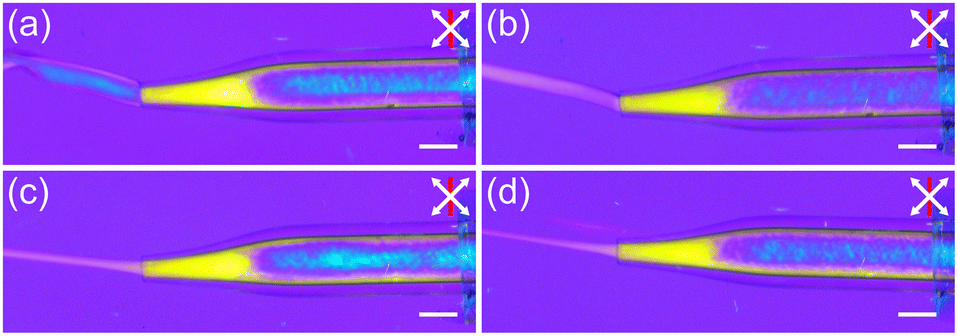 | ||
| Fig. 3 In situ polarised optical micrographs of INT fibre spinning with (a) no draw applied and (b–d) a draw ratio of (b) 1, (c) 3 and (d) 5. White arrows indicate the polariser and analyser directions, and red lines indicate the slow axis direction of a 560 nm full-wave retardation plate. Scale bars 1 mm. | ||
In order to assess the effect of draw ratio (DR) on fibre properties, fibres were spun with draw ratios of 1, 2, 3, 4 and 5. The gel fibres were washed in deionised (DI) water to remove residual CaCl2 by manually dipping the fibres two times for 3 s. The washed fibres were hung to dry with a small weight (∼20 mg) in ambient conditions. The resulting water-washed (WW) fibres were imaged using transmission optical microscopy and the mechanical properties were measured using a single filament tensile test at controlled humidity.
As expected, the cross-sectional areas of the dry fibres decreased with draw ratio (Fig. 4a). However, in addition, the INT packing density, determined as the volume of INTs divided by the fibre volume (ESI Note 1†), tended to increase across the series (Fig. 4b). For DR 1, the packing density was estimated to be 25%, rising to 60% at DR 4, although then decreasing to 47% at DR 5. This trend is reflected in the tensile data with the tenacities increasing with draw ratio at both 10 and 40% RH (Fig. 4c). Since tenacity depends on linear density, not cross-section, the increase indicates more efficient use of the INTs, due to better inter-tube load transfer at higher packing density. The relative increase in strength (Fig. 4d) is even greater as the better packing density also reduces the fibre cross-section (Fig. 4d).
 | ||
| Fig. 4 (a) Diameter, (b) packing density, (c) tenacity and (d) tensile strength of INT fibres prepared by coagulation in CaCl2 with a tapered spinneret at varying draw ratio followed by washing in DI water (3 × 2 s). Magenta bars indicate samples tested at 10% RH, cyan bars for samples tested at 40% RH. Error bars show ±1 standard deviation. | ||
Qualitatively, the fibres prepared at DR 1 appeared wetter than the other fibre samples and glistened under standard lab illumination, indicating that the CaCl2 coagulant was not fully removed during washing. For the consistent washing treatment used here, the efficiency of the washing depends upon the diameter of the gel fibre; a longer time period is required to allow salt to diffuse from the larger fibres. The improved mechanical properties in the fibres with the higher draw ratio can, therefore, be largely attributed to the more efficient removal of the coagulation salt which increases both packing density and the associated number of nanotube contacts within the fibre.
Washing strategies for microstructural control
Since fibres collected directly from the CaCl2 bath cannot fully dry under ambient conditions, due to the presence of the hygroscopic salt within them (Fig. S4†), a water wash is needed to remove excess salt and enable densification. However, this water washing leads to swelling and solubilisation of the INT gel fibres, causing them to become significantly weaker and more challenging to handle, over time. After 1 minute, it was not possible to remove the fibre from the washing bath in a continuous piece and after 10 minutes the fibre almost completely dissolved. Changes to the gel fibre during washing were observed using in situ POM (Fig. S5†). After just 10 s of immersion, the gel fibres clearly swell compared to their initial state, and this swelling increased over time with fibrillation visibly occurring after 5 minutes. During the washing process, the intensity of the birefringence colours decreased due to both the reduced concentration of the swollen gel and likely a reduction in alignment.POM was then used to observe the evolution of the microstructure of the final, dried, INT fibres as a function of washing time (Fig. 5). Fibres were spun at two different draw ratios (2 and 4), dipped into water for 5, 10, 20 or 40 s, and then dried under tension (∼20 mg). Fibres washed for 5 s never completely dry under ambient conditions and had a larger diameter and glistening wet appearance under the microscope. After a critical washing time of ∼20 s for DR 2 (Fig. 5), the fibre birefringence changed significantly. With the fibre positioned at 45° to the crossed polarisers, the total retardation increased from ∼200 nm at short washing times to ∼500 nm after longer washes. This higher retardation likely arises due to the improved densification after long washes, where a greater quantity of INTs are packed into the light path for the thinner, denser fibres. At the same time, after longer washes, a significantly stronger birefringent signal can be seen when the fibre is aligned parallel to the analyser, showing a greater degree of misalignment. These changes indicate that after longer washing times, the dried fibres have an increased INT packing density but contain more bundles which are misaligned relative to the fibre axis. The simultaneous increase in packing density and decrease in alignment may seem counter-intuitive when considering simple packing of rigid rods. However, in this case, the structural rearrangements occur alongside the removal of highly hygroscopic salt from the fibres. The more aligned fibres from shorter washing times are swollen with adsorbed water, the deliquescence of which can be visualised, which leads to their lower packing density.
 | ||
| Fig. 5 Polarised optical micrographs of dry INT fibres produced with DR 2 and washed by submersion in water for varying periods of time. White arrows indicate the polariser and analyser directions, and red lines indicate the slow axis direction of a 560 nm full-wave retardation plate. Scale bars 100 μm. | ||
Having identified that washing conditions lead to significant changes in INT fibre morphology, an inline washing bath was introduced to the wet spinning rig to provide greater experimental consistency during continuous spinning. After initial draw and take-up from the coagulation bath the gel fibre was passed via guide rods through DI water baths of length 15, 30 and 40 cm corresponding to washing times varying between 8 and 23 s for DR 2, and 4 and 11.5 s for DR 4. It was not possible to use longer washing baths due to weakening of the gel fibre leading to frequent filament breakage on the continuous spinning line.
As before, structural changes in the dried fibres were observed under POM with increased retardation at longer washing times. The POM observations again indicate the occurrence of two key processes: diffusion of CaCl2 out of the gel fibre and structural rearrangement of the INTs due to partial solubilisation. The significance of these processes may be compared by considering the characteristic time scales over which they occur.
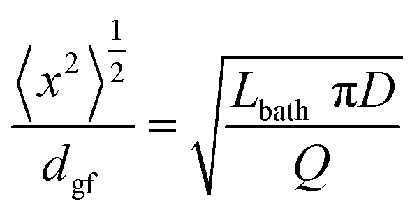
The characteristic diffusion time required for calcium and chloride ions to be washed from the gel fibre can be estimated by considering diffusion of the salt as the random walk of a Brownian particle radially (perpendicular) to the fibre axis. The root mean squared displacement in this random walk is given by,
 | (1) |
The characteristic timescale for structural rearrangement can be estimated as τr ∼ 1/Dr where Dr is the rotational diffusion coefficient for the INTs in the fibre. By modelling the INTs in the gel fibre as a semi-dilute suspension of thin rigid rods with a concentration equivalent to the spinning dope, the rotational diffusion coefficient can be determined by following Doi31 as,
 | (2) |
Wide angle X-ray scattering was used to characterise, further, the relationship between draw ratio, washing and the INT alignment. The fibre scattering patterns show the typical features of the DW Ge-INTs used in this work with large oscillations visible on the equatorial line at scattering vectors of 2.6, 5.4 and 7.3 nm−1 (Fig. S6†). The alignment was characterised by fitting the angular dependence of the scattered intensity at 2.6 nm−1 to a Lorentzian function. As previously described,13,32,33 the reciprocal space Lorentzian of the X-ray scattering pattern arises from a direct space orientational distribution function (ODF) of a Lorentzian to the power 1.5, with a half-width-at-half-maximum (HWHM), wd = 0.775 wr, where wr is the HWHM of the Lorentzian fit to the reciprocal space diffraction data. The Hermans' order parameter, S, is then calculated from the ODF as
 | (3) |
 | (4) |
 | ||
| Fig. 6 Hermans orientation parameter for INT fibres spun at (blue circles) DR 2 and (red triangles) DR 4 as a function of (a) the washing time and (b) the CaCl2 diffusion distance divided by the initial gel fibre diameter. | ||
Mechanical properties as a function of processing conditions
The tensile mechanical properties of these fibres show that longer washing baths resulted in significantly stiffer and stronger fibres which tended to have smaller strains to failure (Fig. 7a and b). For example, for DR 4, the tensile strength increased from 20 ± 4 to 170 ± 30 MPa, the modulus increased from 4.3 ± 1.7 to 23 ± 2 GPa and the strain-at-failure decreased from 1.8 ± 0.7 to 1.3 ± 0.3% as the washing bath length increased from 15 to 40 cm. The packing density, alignment, stiffness, strength, tenacity and strain-at-failure all follow the same trends for both draw ratios (Fig. 7c–h), in agreement with the prediction that washing bath length (eqn (4)) is the critical process factor affecting the fibre properties.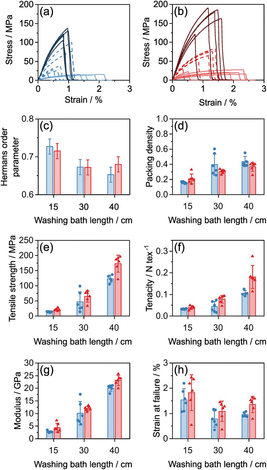 | ||
| Fig. 7 (a, b) Stress strain curves for INT fibres spun at (a) DR 2, (b) DR 4 using a tapered spinneret. Dark solid lines 40 cm washing bath, medium dashed lines 30 cm washing bath, light solid lines 15 cm washing bath. (c–h) Structural and mechanical parameters for (blue) DR 2 fibres and (red) DR 4 fibres with varying washing bath lengths. Error bars indicate 1 standard deviation. | ||
As washing bath length increases, the INT orientation reduces (Fig. 7c), in agreement with previous data that less aligned INT fibres are stiffer13 but now identifies that both the removal of CaCl2 and structural rearrangements during washing are contributing process factors. As the bath length increased from 15 cm to 30 cm, packing density also increased from ∼20% to ∼40%. Whilst it is difficult to separate the effects of packing density and orientation, increased strength and stiffness can be attributed to the formation of an interlocked network of the misaligned INTs. Compared to other nanomaterial fibres such as CNT fibres, the INTs used here are relatively short (mostly 200–600 nm) and are extremely straight and rigid, as can be seen in previous TEM images.13 As such, the typical model of nanotube stress transfer due to van der Waals' interactions within locally parallel bundles is less relevant within these fibres. The rigid nanotubes cannot easily bend to form contacts, or parallel bundles, and hence they have a low contact area and poor stress transfer. In the more aligned fibres, ductile sliding can occur easily without arrest which results in the lower strengths and higher strains to failure seen at short washing lengths. In contrast, less aligned structures may transfer stress through a network of jammed frictional rods. The formation of these jammed networks occurs when the number of independent contacts on each rod reaches a critical value of around ten.34 Increasing packing density and increasing misalignment both help to create additional independent contacts between INTs, leading to the formation of a percolating network which can transfer tensile loads. Similar stress transfer networks have been formed by creating branched aramid nanofibers which have greater interconnectivity.35 These data match observations of shear thickening in suspensions of colloidal rods where sudden increases in shear stress are associated with the formation of a disordered percolating network, which has greater frictional interactions in this shear jammed state.36 Whilst there is a lack of models directly studying the effect of alignment on the mechanical properties of rod networks, recent progress has been made comparing the elasticity of rod and L-shaped particles in randomly oriented networks37,38 and it is expected that these approaches may be extended to explore other orientation distribution functions. A key existing result is that rod networks are always shear thinning, implying that as the alignment of the network increases during shear, its elasticity decreases in direct agreement with the argument presented above. In comparison, the constraints of the surrounding network on L-shaped particles can force them to bend leading to a shear thickening behaviour. Following this model, it may be beneficial to explore synthesis routes which create INTs with bends or kinks that further constrain the network and contribute to stress transfer.
INT fibres were also spun using a cylindrical capillary as the spinneret, showing properties in similar ranges, but with no clear trends within the large experimental scatter (Fig. S7†). Given the misalignment in the core of cylindrical nozzles (Fig. 1c), there fibres were expected to have locally variable alignment, both radially, and longitudinally due to the retained domain structure of the spinning dope. The variable structure gives rise to variable properties. In comparison, the more homogeneous gel fibre extruded from the tapered spinneret results in significantly more consistent properties, again emphasising the advantages of using the extensional flow field of the tapered spinneret to align the nematic spin dope.
Gel cross-linking of INT fibres
The mechanical properties of the water-washed (WW) INT fibres have been shown to be dependent upon alignment and packing fraction, as the inter-nanotube contacts are highly mobile and require jamming constraints for effective stress transfer. Logically, it should be possible to create stiffer networks of more aligned INTs by cross-linking to increase the inter-nanotube shear strength.Inspiration for cross-linking was taken from sodium alginate gels which can be physically cross-linked with divalent cations such as calcium to create robust networks.39 A potential beneficial side-effect is that successful gels may be water stable, enabling a greater range of washing conditions. By analogy to alginates, it was hypothesised that inorganic salt solutions with multivalent anions would effectively gel INT solutions, assuming that ionic cross-links form between the positively-charged outer surfaces of the INTs. Experimentally, INT dope was injected by hand through a 21 g needle into a small vial (30 mL) of coagulant solution. The resulting gel fibres were collected and placed in a Petri dish of deionised water and the condition of the gel fibre was qualitatively assessed at various intervals by gently handling the fibre with tweezers and noting it as either robust or fragile (Table 1).
| Coagulant | Washing time/minutes | ||||
|---|---|---|---|---|---|
| 0.5 | 1 | 5 | 10 | 30 | |
| Sodium chloride | × | ||||
| Calcium chloride | ✓ | × | |||
| Sodium citrate | ✓ | ✓ | ✓ | ✓ | ✓ |
| Sodium succinate | ✓ | ✓ | ✓ | ✓ | ✓ |
| Sodium tripolyphosphate | ✓ | ✓ | ✓ | ✓ | ✓ |
| Sodium sulphate | ✓ | ✓ | ✓ | ✓ | ✓ |
Fibres coagulated in salts with monovalent anions (NaCl and CaCl2) rapidly weakened when soaked in water irrespective of the cation valency. However, fibres coagulated in salts with multivalent anions remained robust even with prolonged soaking in water (over 30 minutes) indicating the success of the ionic cross-linking strategy. However, trials seeking to draw fibres spun into cross-linking coagulants were unsuccessful, across a broad range of coagulant concentrations from 0.001 to 1 M. Instead of deforming smoothly at the spinneret nozzle, the proto-fibres fractured uncontrollably. This behaviour is likely due to the formation of a rigid network on the surface of the proto-fibre which cannot stably draw under the elongation. The resulting increase in elastic stress within the fibre results in its abrupt failure.
Gel cross-linked fibres (GCL) were instead prepared by initial spinning into a CaCl2 coagulation bath and then washing in a 0.1 M solution of sodium succinate (2 × 15 s). Compared to water washed fibres (WW), the GCL fibres' mechanical behaviour was significantly less sensitive to humidity, indicating that the cross-linking sites inhibit the moisture mediated sliding previously seen in pure INT fibres. However, the absolute mechanical properties of the GCL fibres were significantly worse than WW fibres, with a larger cross-sectional area, smaller tensile strength and smaller tenacity (and hence breaking force) for equivalent conditions (Fig. S8†).
The significantly larger cross-sectional area for GCL fibres results from poor densification of the gel fibres during drying. The formation of the rigid network apparently inhibits diametral shrinkage and prevents the formation of additional contact points between INTs, leading to a more porous structure which is less able to transfer stress. Importantly, the difference in strength between the GCL and WW fibres is not simply due to the different cross-sectional area, since there is also a reduction in the absolute breaking force and hence tenacity of the fibres.
This ionic cross-linking method can create robust aqueous gels resistant to redissolution, which may be useful in other contexts. However, these cross-linked gel fibres are not attractive as a route to improved, dense fibres. Instead, in order to improve humidity stability and yield potential improvements to fibre strength, cross-linking strategies should be targeted on dry, pre-densified fibres.
Conclusions
The structure and properties of pure INT fibres are controlled via several process variables in wet spinning. The shear thinning rheology of INT solutions creates challenges during spinning as plug flow in cylindrical spinnerets leads to inhomogeneous alignment in the dope and inconsistent fibre properties. Tapered spinnerets, which induce extensional flow fields, ensure deformation throughout the spin dope resulting in significantly more aligned and homogeneous gel fibres and correspondingly more consistent fibre properties. Tapered spinnerets are widely used in commercial processes, but should be considered more often in new materials development labs, where cylindrical needles often dominate; in situ observations will help to optimise geometries to dopes with different rheologies.Spinning pure fibres from short, rigid nanotubes is quite different to typical composite systems, in which a matrix transfers stress between the rigid elements. The properties of pure porous INT fibres depend strongly on both misalignment and packing fraction. It is proposed that the formation of jammed, mechanically percolating rod networks underpin the increase in strength and stiffness with decreasing INT alignment. Fibre microstructure can be controlled by washing the gel fibre in DI water. Longer washing times lead to the removal of hygroscopic salt, and improved densification, whilst at the same time allowing structural relaxation leading to a greater amount of off-axis INTs. These two processes are strongly coupled during the wet spinning of INT fibres and occur over similar time scales, making it challenging to independently investigate the effects. Similar washing and relaxation processes will occur in many (nanomaterial) systems, and may be better understood by in situ analysis.
INTs can be simply crosslinked using multivalent anions to form robust aqueous gels resistant to redissolution. In the context of structural fibres, cross-linking the wet proto-fibres locks in a swollen state, limiting consolidation and leading to poorer mechanical properties than unlinked fibres. However, in other contexts proposed for imogolite based materials, for example as sorbents or catalyst supports, the ability to create stable, porous, network structures may prove useful.
The best process identified for creating consistent, high strength INT fibres uses a tapered spinneret to achieve a homogeneous dope followed by drawing in a CaCl2 coagulant, that allows for deformation and then washing in DI water; the result is a pure, relatively dense, jammed network structure suitable for tensile stress transfer. Although cross-linking INT fibres in the gel state has not improved the mechanical properties due to challenges with densification, increasing the shear strength of the inter-nanotube contacts in the dense, dry fibres should lead to increased strength and stiffness. Possible methods may include cross-linking via dehydration reactions or infiltrating polymer matrices. The preference for tapered spinnerets and delaying any permanent cross-linking until after consolidation is likely relevant to other one dimensional nanomaterial fibres, including CNT and other nanorod systems. In situ analysis is a key tool to accelerate the understanding and development of coagulation spinning processes.
Author contributions
Conceptualisation: JFM, MSPS; formal analysis: JFM, EP; investigation: JFM; software: PL; validation: PL; supervision: PL, MSPS; writing – original draft: JFM; writing – review and editing: EP, PL, MSPS.Conflicts of interest
There are no conflicts to declare.Acknowledgements
The authors would like to thank Dstl for the funding received for this project through the UK-France PhD Scheme. The authors would like to acknowledge the use of characterization facilities within the Harvey Flower Electron Microscopy Suite, Department of Materials, Imperial College London, and EPSRC Programme Grant EP/I02946X/1: High Performance Ductile Composite Technology (HiPerDuCT), in collaboration with the University of Bristol. The present work has benefited from the Imagerie-Gif core facility supported by the l’Agence Nationale de la Recherche (ANR-11-EQPX-0029/Morphoscope; ANR-10-INBS-04/FranceBioImaging; ANR-11-IDEX-0003-02/Saclay Plant Sciences). X-ray scattering experiments were performed on the MORPHEUS platform of experiments at the Laboratoire de Physique des Solides (Orsay, France). We thank S. Rouzière, P.-A. Albouy and C. Hamon for their support with the X-ray scattering experiments.Notes and references
- J. N. Coleman, U. Khan, W. J. Blau and Y. K. Gun'ko, Carbon, 2006, 44, 1624–1652 CrossRef CAS.
- N. Hiremath, J. Mays and G. Bhat, Polym. Rev., 2017, 57, 339–368 CrossRef CAS.
- A. Lekawa-Raus, J. Patmore, L. Kurzepa, J. Bulmer and K. Koziol, Adv. Funct. Mater., 2014, 24, 3661–3682 CrossRef CAS.
- N. Behabtu, C. C. Young, D. E. Tsentalovich, O. Kleinerman, X. Wang, A. W. K. Ma, E. A. Bengio, R. F. ter Waarbeek, J. J. de Jong, R. E. Hoogerwerf, S. B. Fairchild, J. B. Ferguson, B. Maruyama, J. Kono, Y. Talmon, Y. Cohen, M. J. Otto and M. Pasquali, Science, 2013, 339, 182–186 CrossRef CAS PubMed.
- L. Qian, Y. Xie, M. Zou and J. Zhang, J. Am. Chem. Soc., 2021, 143, 18805–18819 CrossRef CAS PubMed.
- A. Mikhalchan and J. J. Vilatela, Carbon, 2019, 150, 191–215 CrossRef CAS.
- J. Lee, D. M. Lee, Y. Jung, J. Park, H. S. Lee, Y. K. Kim, C. R. Park, H. S. Jeong and S. M. Kim, Nat. Commun., 2019, 10, 2962 CrossRef PubMed.
- W. Xu, Y. Chen, H. Zhan and J. N. Wang, Nano Lett., 2016, 16, 946–952 CrossRef CAS PubMed.
- D.-M. Lee, J. Park, J. Lee, S.-H. Lee, S.-H. Kim, S. M. Kim and H. S. Jeong, Carbon, 2021, 172, 733–741 CrossRef CAS.
- H. Zhan, Y. W. Chen, Q. Q. Shi, Y. Zhang, R. W. Mo and J. N. Wang, Carbon, 2022, 186, 205–214 CrossRef CAS.
- H. Cho, H. Lee, E. Oh, S.-H. Lee, J. Park, H. J. Park, S.-B. Yoon, C.-H. Lee, G.-H. Kwak, W. J. Lee, J. Kim, J. E. Kim and K.-H. Lee, Carbon, 2018, 136, 409–416 CrossRef CAS.
- J. C. Fernández-Toribio, B. Alemán, Á. Ridruejo and J. J. Vilatela, Carbon, 2018, 133, 44–52 CrossRef.
- J. F. Moore, E. Paineau, P. Launois and M. S. P. Shaffer, ACS Appl. Mater. Interfaces, 2021, 13, 17940–17947 CrossRef CAS PubMed.
- E. Paineau, S. Rouziere, G. Monet, C. C. Diogo, I. Morfin and P. Launois, J. Colloid Interface Sci., 2020, 580, 275–285 CrossRef CAS PubMed.
- M. S. Amara, E. Paineau, M. Bacia-Verloop, M. E. Krapf, P. Davidson, L. Belloni, C. Levard, J. Rose, P. Launois and A. Thill, Chem. Commun., 2013, 49, 11284–11286 RSC.
- E. Paineau, G. Monet, V. Peyre, C. Goldmann, S. Rouziere and P. Launois, Langmuir, 2019, 35, 12451–12459 CrossRef CAS PubMed.
- C.-Y. Su, Q. Lyu, D.-Y. Kang, Z.-H. Yang, C. H. Lam, Y.-H. Chen, S.-C. Lo, C.-C. Hua and L.-C. Lin, Phys. Rev. Lett., 2019, 123, 238002 CrossRef CAS PubMed.
- E. Paineau, M. E. Krapf, M. S. Amara, N. V. Matskova, I. Dozov, S. Rouziere, A. Thill, P. Launois and P. Davidson, Nat. Commun., 2016, 7, 10271 CrossRef CAS PubMed.
- V. Faraoni, M. Grosso, S. Crescitelli and P. L. Maffettone, J. Rheol., 1999, 43, 829–843 CrossRef CAS.
- K. Walters, Rheometry, Chapman & Hall, London, 1975 Search PubMed.
- C. Lang, J. Kohlbrecher, L. Porcar, A. Radulescu, K. Sellinghoff, J. K. G. Dhont and M. P. Lettinga, Macromolecules, 2019, 52, 9604–9612 CrossRef CAS.
- C. Lang, J. Kohlbrecher, L. Porcar and M. P. Lettinga, Polymers, 2016, 8, 291 CrossRef PubMed.
- G. Cavallaro, G. Lazzara, F. Pignon, L. Chiappisi and E. Paineau, Langmuir, 2021, 37, 9858–9864 CrossRef CAS PubMed.
- D. Quemada and C. Berli, Adv. Colloid Interface Sci., 2002, 98, 51–85 CrossRef CAS PubMed.
- C. Baravian, D. Vantelon and F. Thomas, Langmuir, 2003, 19, 8109–8114 CrossRef CAS.
- Y. Tsujimoto, A. Yoshida, M. Kobayashi and Y. Adachi, Colloids Surf., A, 2013, 435, 109–114 CrossRef CAS.
- G. Natale, M. C. Heuzey, P. J. Carreau, G. Ausias and J. Férec, AIChE J., 2014, 60, 1476–1487 CrossRef CAS.
- V. Calabrese, S. J. Haward and A. Q. Shen, Macromolecules, 2021, 54, 4176–4185 CrossRef CAS.
- H. C. Berg, Diffusion: microscopic theory, in Random walks in biology, Princeton University Press, 2018, pp. 5–16 Search PubMed.
- P. A. Lyons and J. F. Riley, J. Am. Chem. Soc., 1954, 76, 5216–5220 CrossRef CAS.
- M. Doi, J. Phys., 1975, 36, 607–611 CrossRef CAS.
- W. J. Lee, E. Paineau, D. B. Anthony, Y. Gao, H. S. Leese, S. Rouziere, P. Launois and M. S. P. Shaffer, ACS Nano, 2020, 14, 5570–5580 CrossRef CAS PubMed.
- V. Pichot, PhD, Université Paris XI, 2005.
- A. Wouterse, S. Luding and A. P. Philipse, Granular Matter, 2009, 11, 169–177 CrossRef.
- J. Zhu, M. Yang, A. Emre, J. H. Bahng, L. Xu, J. Yeom, B. Yeom, Y. Kim, K. Johnson, P. Green and N. A. Kotov, Angew. Chem., Int. Ed., 2017, 56, 11744–11748 CrossRef CAS PubMed.
- V. Rathee, S. Arora, D. L. Blair, J. S. Urbach, A. K. Sood and R. Ganapathy, Phys. Rev. E, 2020, 101, 040601 CrossRef CAS PubMed.
- D. A. King, M. Doi and E. Eiser, J. Chem. Phys., 2021, 154, 244904 CrossRef CAS PubMed.
- D. A. King, M. Doi and E. Eiser, J. Chem. Phys., 2021, 154, 244905 CrossRef CAS PubMed.
- K. Y. Lee and D. J. Mooney, Prog. Polym. Sci., 2012, 37, 106–126 CrossRef CAS PubMed.
Footnote |
| † Electronic supplementary information (ESI) available: POM and SAXS of INT spinning dopes; in situ POM of fibre washing/drying; WAXS of INT fibres and associated orientational fitting parameters; mechanical/physical data for INT fibres spun from cylindrical spinnerets and after gelation; derivation of eqn (4); POM videos of flow through different spinnerets. See DOI: https://doi.org/10.1039/d3na00013c |
| This journal is © The Royal Society of Chemistry 2023 |