
 Open Access Article
 This Open Access Article is licensed under a Creative Commons Attribution-Non Commercial 3.0 Unported Licence
Directional Bloch surface wave coupling enabled by magnetic spin-momentum locking of light †
Kaiwen
Luo
 a,
Zhijing
Huang
ac,
Xianpeng
Lv
a,
Wentao
Qiu
a,
Heyuan
Guan
a,
Tiefeng
Yang
ad,
Thierry
Grosjean
*b and
Huihui
Lu
*ad
a,
Zhijing
Huang
ac,
Xianpeng
Lv
a,
Wentao
Qiu
a,
Heyuan
Guan
a,
Tiefeng
Yang
ad,
Thierry
Grosjean
*b and
Huihui
Lu
*ad
aGuangdong Provincial Key Laboratory of Optical Fiber Sensing and Communications, Department of Optoelectronic Engineering, Jinan University, Guangzhou 510632, China. E-mail: thuihuilu@jnu.edu.cn
bCNRS, FEMTO-ST Institute UMR 6174, Université Bourgogne Franche-Comté, Besançon 25000, France. E-mail: thierry.grosjean@univ-fcomte.fr
cSchool of Electronics and Communication, Guangdong Mechanical and Electrical Polytechnic, Guangzhou 510550, China
dKey Laboratory of Optoelectronic Information and Sensing Technologies of Guangdong Higher Education Institutes, Jinan University, Guangzhou 510632, China
First published on 6th February 2023
Abstract
We study the magnetic spin-locking of optical surface waves. Through an angular spectrum approach and numerical simulations, we predict that a spinning magnetic dipole develops a directional coupling of light to transverse electric (TE) polarized Bloch surface waves (BSWs). A high-index nanoparticle as a magnetic dipole and nano-coupler is placed on top of a one-dimensional photonic crystal to couple light into BSWs. Upon circularly polarized illumination, it mimics the spinning magnetic dipole. We find that the helicity of the light impinging on the nano-coupler controls the directionality of emerging BSWs. Furthermore, identical silicon strip waveguides are configured on the two sides of the nano-coupler to confine and guide the BSWs. We achieve a directional nano-routing of BSWs with circularly polarized illumination. Such a directional coupling phenomenon is proved to be solely mediated by the optical magnetic field. This offers opportunities for directional switching and polarization sorting by controlling optical flows in ultra-compact architectures and enables the investigation of the magnetic polarization properties of light.
Introduction
Recent advances in nanophotonics have revealed the hidden role of magnetic field in light–matter interactions. An enhanced optical magnetic response can be obtained by using resonant metallic and dielectric nanostructures, which underpins a plethora of novel phenomena and applications such as negative refractive indices,1–4 controlling magnetic transitions,5–8 mapping optical magnetic field,9–14etc. Besides, the magnetic component of light also contributes to the total spin density15 and plays a significant role in optical spin–orbit interactions (SOIs).16,17 It has been shown that by means of SOIs, remarkable magnetic effects can be achieved without optical resonances in nanostructures, which brings a new degree of freedom to light sensing and manipulation.Our research refers to the spin-momentum locking of light—an optical SOI effect associated with evanescent waves. In such waves, the elliptically polarized electric or magnetic field describes a transverse spin angular momentum whose sign flips when propagating along opposite directions. With a subwavelength (dipolar) coupler, the longitudinal spin angular momentum (SAM) of an impinging wave can be transferred into the transverse SAM of the evanescent tail of a guided mode, leading to a directional light coupling and guiding wave. This robust spin-controlled directionality has been demonstrated with various optical systems including nanofibers,18 waveguides,19–22 and surface wave modes.23–27 So far, most investigations focused on using the rotating electric component of light as the source of SAM for originating the transverse spin-direction coupling.27–29 A recent study demonstrated that the magnetic component of light can play the same role of offering SAM in the SOI of light.17 In that work, the light coupler has an electric dipole response, leading to a power conversion to the waves driven by the electric optical field. The magnetic field is only responsible for the directionality control of the Bloch surface waves (BSWs). Here, to exclude any influence from the electric field in the coupling process, we turn to use a magnetic dipole (MD) coupler which can be configured by shaping a nanoparticle and show a pure magnetic coupling of light to BSWs. BSWs are electromagnetic surface waves excited at the interface between a periodic dielectric multilayer and its surrounding medium,17 and they can be excited by both TE- and TM-polarized waves, which offers an appropriate platform for the manipulation of polarization.
High-index dielectric nanoparticles can support MD mode. Working on Mie resonance, strong volume displacement currents are induced in these nanoparticles, which promotes the effective magnetic polarizability to be comparable or even stronger than the electric polarizability.30,31 High-index dielectric nanoparticles thus provide a versatile platform for studying magnetic light–matter interactions.30,32–34 Furthermore, the spectral position and relative strength of electric and magnetic optical resonances can also be independently tailored by changing the shape35 and composition36–38 of the nanoparticle. By this approach, a directional far-field scattering has been achieved. Besides, the huge potential of high-index dielectric nanoantennas for directional excitation of surface waves and their highly efficient demultiplexing has been revealed.35
In this paper, we study the spin-locking of BSWs solely mediated by the magnetic field of light. BSWs are surface modes propagating on top of a one-dimensional photonic crystal (1D-PC). We configure the dielectric multilayers of our 1D-PC to ensure a pure TE-polarized BSW mode in which only the magnetic field spins. A Mie scatterer is used as a near-field light-to-BSW coupler and circularly polarized light is projected onto the scatterer for studying the directional excitation of BSWs. We find that the excitation directionality of BSWs can be manipulated by spin-locking the magnetic SOI of light. This demonstration offers opportunities for directional switching and polarization sorting by controlling optical flows in ultra-compact architectures and enables the analysis of the polarization properties of light.
Results and discussion
Angular spectrum representation of a dipole source
To start with, we consider a dipole source positioned just above a dielectric waveguide as shown in Fig. 1(a). The dipole moment is represented by d = [dx, dz], where dx and dz are the projections on the x- and z-axes, respectively. Such a model suffices to describe the scattering behavior of a Rayleigh particle,27 which herein lays the theoretical foundation for our study.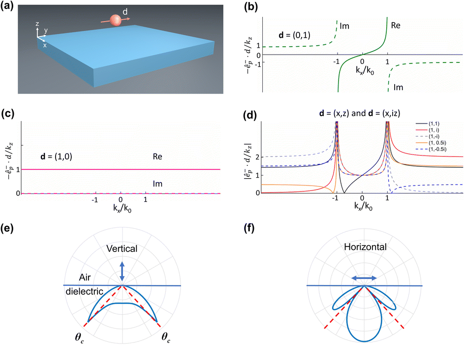 | ||
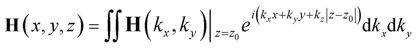
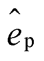
| Fig. 1 (a) Schematic of a dipole source placed near a dielectric waveguide. (b) Angular spectrum presentation of a vertically oriented linear dipole; (c) angular spectrum representation of a horizontally-orientated linear dipole; (d) angular spectrum representation of linear and rotating magnetic (electric) dipoles with various helicities. (e and f) Emission patterns in the dielectric when linear dipoles (vertical dipole and horizontal dipole) are placed 10 nm above the dielectric/air interface. | ||
The dipole source is assumed located in air with a vertical distance z0 from the top surface of the waveguide. Its interaction with the waveguide can be described by Fermi's Golden Rule.18,39–41 The directional excitation of the waveguide refers to the asymmetric distribution of the total coupled energy in the two counter-propagating guided waves. Such a coupling directionality originates from the interference of the respective optical excitations aroused by the two orthogonal components of the dipolar moment (dx and dz), which can be either destructive or constructive depending upon the propagation direction. In general, a properly chosen polarization of the dipole will result in destructive interference in one prescribed direction and a mode propagating in the opposite direction.16,27,42 Alternatively, this directional phenomenon can be interpreted from the dipole side by inspecting its angular spectrum.16,42
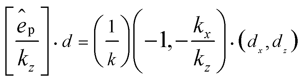
Following the angular momentum approach, a magnetic (electric) field can be resolved into a set of plane-wave and evanescent-wave components:
 | (1) |
 .16 We have:
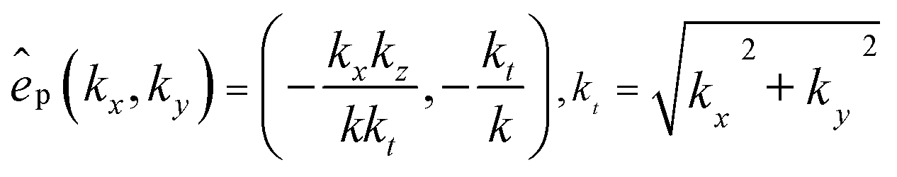 | (2) |
To better understand the spin-locking effect while coupling a spinning dipole (elliptically or circularly polarized) to evanescent waves, we measure the dipolar directionality factor as follows:16
 | (3) |
Fig. 1(b) and (c) show the angular spectra of a dipole oriented in the z- and x-directions, respectively. We can see that the angular spectrum is an odd function of kx for the vertical dipole while even for the horizontal one. The superposition of the two dipoles can therefore lead to a strongly asymmetric function of kx. By combing the two orthogonal dipoles with proper linear coefficients, the angular spectra of the dipoles with various polarization states are obtained and plotted in Fig. 1(d). The composed dipolar field varies with the polarization state of the dipole. Remarkably, in certain cases, distinct symmetries appear in the propagating and evanescent spatial components.
As shown in Fig. 1(d), the evanescent angular spectrum (|kx| > k0, where k02 = kx2 + kz2) of an elliptically or circularly polarized dipole is strongly asymmetric to kx, which is in favor of directionality in their near-field interaction with matter. The propagating components of these dipoles (|kx| < k0), however, are always symmetric disregarding the sign of kx. Such a difference means that one can expect a directional phenomenon from a spinning dipole only by presenting it in proximity to the waveguide. In this way, the evanescent fields associated with the dipole and guided mode overlap and hence crosstalk efficiently. It is noted that, by introducing nanostructures to locally break the symmetry of an optical waveguide, a directional phenomenon can also be realized with linear polarization.43 Nevertheless, when it comes to ordinary waveguides, one loses the directionality since a linear dipole contains symmetric evanescent components, as shown in Fig. 1(e) and (f).
Quantitative assessment of the coupling directionality of a dipole to a waveguide can be made following the procedures described in the literature.16,27,42 The discussion above relates only to the angular components of the dipole itself in the air as shown in Fig. 1(b–d), with no mention being made of the nearby waveguide. When a dipole is placed close to a surface, due to the conservation of transverse momentum, the probability of exciting guided modes with specific (kx, ky) is proportional to the amplitude of the corresponding spatial component in the dipolar field, weighted by the Fresnel reflection coefficients.16 Therefore, when a spinning dipole possessing a strongly asymmetric spectrum in its evanescent components is placed near a surface or planar waveguide, it develops a highly directional excitation of the guided modes.16 As can be inferred from Fig. 1(c), a unidirectionality is attainable with proper helicity of the spinning magnetic dipole. Besides, one can play with the coupling directionality by tuning the ellipticity of the magnetic dipole. Such a tunable distribution of the coupled energy is ultimately due to the SAM transfer from the dipole source to the guided mode, which must obey the conservation law of angular momentum.
So far, we have analytically shown that a spinning magnetic dipole could develop a spin-controlled excitation of optical guided modes. To verify that, we numerically investigate the coupling of circularly polarized magnetic and electric dipoles to BSWs by the finite-difference time-domain (FDTD) method with a commercial code (Lumerical FDTD Solutions). To this end, we carry out two sets of simulations with the dipole positioned 10 nm above the top surface of a 1D-PC. The material and geometry of the 1D-PC are shown in Fig. S1 of the ESI,† which is configured as those in previous literature17 so that it supports a pure TE mode at the wavelength of 1550 nm.
Fig. 2 shows the simulation results obtained by using electric and magnetic dipoles of various polarization states to excite the 1D-PC. We can see from Fig. 2 (c–f) that the BSWs excited by a spinning magnetic dipole are strongly unbalanced on the left and right sides. The preferential side is dictated by the handedness of the dipole. In addition, we can find that even if the rotating magnetic dipole is not exactly in circular polarization (1, ±i), the directionality of TE-BSWs still exists, which is aligned with the directionality predicted by the angular momentum. It is noted that, however, a spinning electric dipole polarized in the xz-plane can hardly excite the TE-BSWs, as shown in Fig. S2 of the ESI.† A linearly polarized electric dipole oriented in the y-direction can excite the BSWs but leads to a symmetric distribution on both sides. A tunable directional excitation of the BSWs here is thus solely controlled by the magnetic field of light. Indeed, for TE-polarized BSWs only the magnetic field spins and describes the transverse SAM involved in the spin-locking effects.17
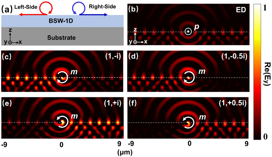 | ||
| Fig. 2 Coupling of circularly polarized magnetic and electric dipoles to BSWs. (a) Model of dipole coupling to BSWs. (b) Y-component of electric field (Re(Ey) > 0) under the illumination of the ED source. (c–f) Y-components of electric field (Re(Ey) > 0) under the illumination of MD sources (1, −i), (1, −0.5i), (1, i), and (1, 0.5i), respectively. | ||
From the above calculations, the directionality predicted by the angular momentum and numerical simulations matches well. Both show a tunable directionality controlled by the optical magnetic field.
Magnetic resonances in nanoparticles
A way to reach a spinning optical magnetic dipole consists of illuminating a dielectric nanosphere with elliptically polarized light. Dielectric nanospheres of high-index (Si, Ge) material are known to support magnetic resonances described by a magnetic moment.32,44 Being spatially isotropic, such nanoparticles placed in a homogeneous environment can produce a spinning magnetic dipole of constant amplitude upon illumination with circularly polarized light.In this paper, we seek a spinning magnetic dipole at the wavelength of 1550 nm. To this end, two types of nanoparticles are investigated: (i) a solid silicon sphere and (ii) a core–shell structure with gold and silicon as the materials of the core and shell, respectively. We numerically study the dependence of scattering resonances on the sizes of these nanoparticles.
Fig. 3(a) shows the scattering spectra of core–shell structures with a constant core radius of 70 nm and various shell radii ranging from 180 nm to 280 nm. As a comparison, Fig. 3(c) displays the scattering spectra of a silicon sphere whose radius is tailored within the same range. The scattering spectra of the two types of nanoparticles share some common characteristics. First, one can recognize three sources of optical resonance: the electric dipole (ED), magnetic dipole (MD), and magnetic quadrupole (MQ) resonances. The relative strength of these resonances varies with the structure size and operation wavelength. Second, the MQ resonance becomes much less significant around the wavelength of 1550 nm though it is remarkable at shorter wavelengths. Finally, in both structures the MD resonance dominates at λ = 1550 nm but for different reasons. As to the core–shell structure, this phenomenon results from the spectral overlapping of the ED and MD resonances as the radius of the silicon shell increases. For the silicon sphere, however, only the MD resonance holds at the wavelength of around 1600 nm. These differences are more clearly shown in Fig. 3(b) and (d), which plot the spectra of the scattering cross-section of the MD and ED resonances, respectively.
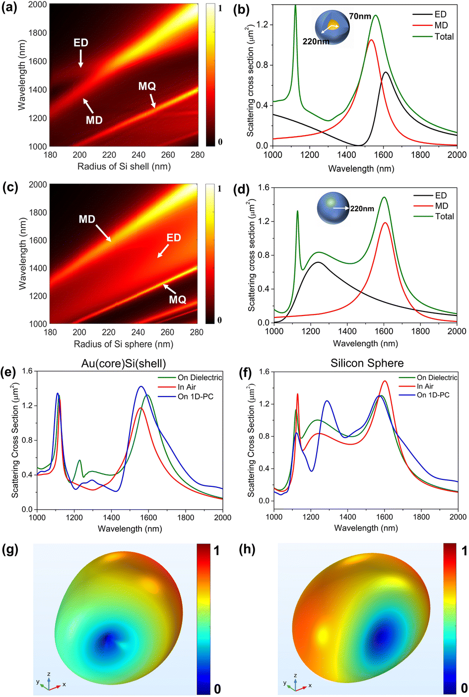 | ||
| Fig. 3 (a) Evolution of Mie resonances of a gold core of 140 nm in diameter with increasing radius of the silicon shell. (b) Decomposition of the scattering spectrum for the Au core/silicon shell nanoparticle. The outer radius R of the silicon shell is 220 nm. (c) Evolution of Mie resonances of a silicon sphere with the increase of radius. (d) Decomposition of the scattering spectrum for the silicon sphere with a radius of 220 nm. (e and f) Substrate modified scattering behavior of nanoparticles for the Au (core) Si (shell) and silicon nanosphere. (g and h) Far-field scattering pattern of the Au (core) Si (shell) nanoparticle and silicon sphere in air at the MD resonance wavelength of 1550 nm, respectively. | ||
From the above discussion, one can see that both the silicon sphere and gold–silicon core–shell structure are good candidates for our purpose. However, it is known that the scattering and resonant properties of a dipolar source will be modified by a substrate present nearby.45–47 We numerically investigate the influences of the substrate on the optical responses of the nanoparticles. Fig. 3(e) and (f) show respectively the simulated scattering cross-section spectra of the two nanoparticles in air and with two types of substrates presented, namely a dielectric slab and the 1D-PC. As shown in Fig. 3(e), the dielectric slab redshifts the MD resonant peak of the core–shell structure to 1600 nm while the 1D-PC only causes a negligible spectral shift. A distinct influence of the substrate is found with the silicon sphere that both the dielectric slab and 1D-PC blue-shift the MD resonance by a comparable amount of 50 nm (see Fig. 3(f)).
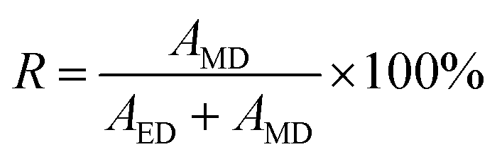
To clearly demonstrate the quantitative relationship between the electric and magnetic responses in nanoparticles, we give the formula to calculate the ratio of the MD components:
 | (4) |
As shown in Fig. S3 of the ESI,† the silicon sphere shows better MD response than the core–shell structure on resonance at λ = 1550 nm. In addition, the MD resonance of the silicon sphere is also blue-shifted by 50 nm due to the influence of 1D-PC, which results in a much larger ratio of the MD than the core–shell structure. The MD-like optical response of the nanoparticles has been further confirmed by inspecting their emission patterns. In these numerical studies, we use a commercial finite-element electromagnetic solver (the RF module of COMSOL Multiphysics). The results are shown in Fig. 3(g), (h) and S4 of the ESI.† Such a doughnut shape characterizes the far field of an MD which is shown in Fig. 3(h). Indeed, if considerable amounts of ED or high-order multipole resonances were involved, the scattering pattern would lose its perfect symmetry.48 Therefore, with the optimal design of the two nanoparticles, we have found that the silicon sphere with a radius of 220 nm exhibits better MD properties than the core–shell structure at λ = 1550 nm in the presence of the 1D-PC.
Directionality control of BSWs from a Si nanosphere on a 1D-PC
By using a near-field coupler, one can couple the optical energy from propagating light to Bloch surface waves. Such couplers can be an individual air groove17 milled in the top layer of the waveguide structure or a nanoparticle positioned just above.49 Fig. S5 of the ESI† shows the symmetric electric field excited by the nanoparticle under the illumination of circularly polarized Gaussian beam at normal incidence, which indicates that the BSWs excited in this case are not directional. In order to observe the spin-locking effect, one needs to illuminate these dipole-like couplers with elliptically polarized light at the glancing angle so that the spinning dipole moment can be excited. In this way, the SAM carried by the free-space photons can be transferred to the transverse SAM of the surface waves during the energy coupling process.17The above-described scheme has been used to demonstrate the spin-locking effects associated with the electric or magnetic fields of light.17 We follow this idea and adopt a silicon sphere as the light-to-BSW coupler (see Fig. 4(a)). It is noted that the nanoparticle merely produces a symmetric field distribution under the illumination of linearly polarized incident light, as shown in Fig. 4(b).
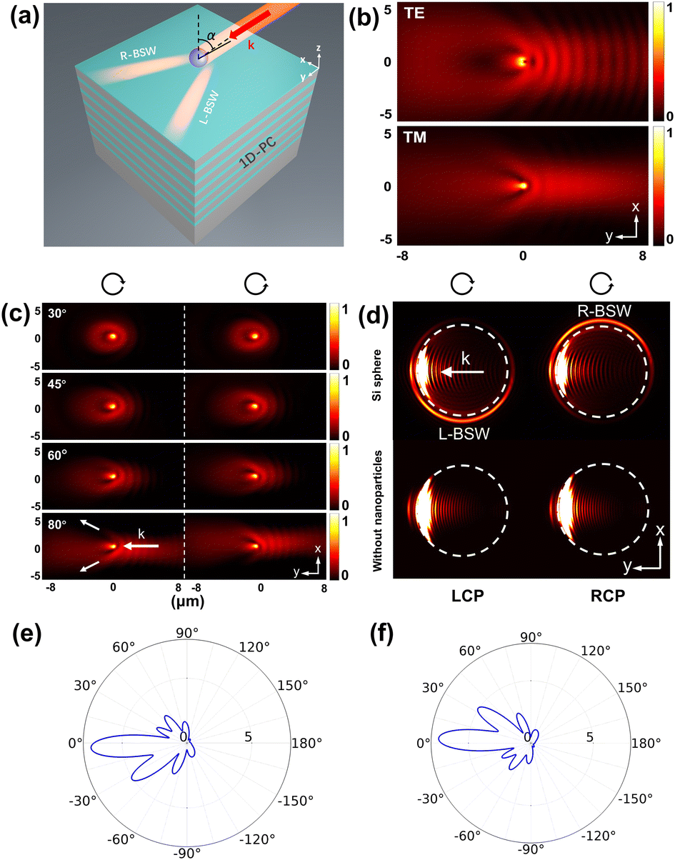 | ||
| Fig. 4 (a) Model of a silicon sphere on 1D-PC illuminated by light at an incidence angle of α. (b) Symmetric electric field distribution under the illumination of linearly polarized light when α = 80° (TE and TM). (c) Electric field distributions under different incident angles of circularly polarized light. (d) Far-field radiation image in circular polarization states of incident light (α = 80°). (e and f) Far-field scattering patterns of the silicon sphere on the 1D-PC under the illumination of left-circularly polarized (LCP) and right-circularly polarized (RCP) incident light (α = 80°), respectively. | ||
We illuminate the nanoparticles at four incidence angles (α = 30°, 45°, 60°, and 80°) to see how the spin-locking effect comes to work. Fig. 4(c) shows the corresponding simulation results obtained with circularly polarized light of opposite handedness. The elongated spot indicated by the thicker white arrow is the cross-section of the excitation beam along the surface of the 1D-PC. The two thinner white arrows mark the emerging BSWs where one can see an unbalanced intensity distribution on the two sides. Besides, the preferential excitation toggles from one side to the other as we inverse the handedness of the incident light, revealing a spin-dependent characteristic of this phenomenon. As the incident angle increases, the intensity distribution asymmetry in the emerging BSWs becomes more and more pronounced. When α = 80°, the coupled energy is almost steered to only one side. To better visualize the asymmetry, we compute the far-field image shown in Fig. 4(d). As can be seen from the figure, no directionality is observed without nanoparticles, but obvious directionality appears after placing the silicon sphere, which demonstrates a directional BSW excitation. Moreover, Fig. 4(e) and (f) show that under the illumination of circularly polarized incident light when α = 80°, the BSWs on the side of stronger intensity are off-center by about 30°.
We see above that the coupling directionality improves as the incident angle increases. That is because the SAM of the BSWs is transverse while that of the incident photons is longitudinal regarding their respective propagation directions. A larger incident angle of the impinging light will lead to a better alignment of the two SAMs and thus a higher coupling directionality. In purely TE-polarized BSWs, only the magnetic field rotates. Therefore, the observed spin-locking directionality is solely controlled by the magnetic field of the incident light.
The energy coupling to BSWs
We also numerically study the directional excitation of BSWs in a more realistic optical setup suggested in the literature [17]: light passes through a fixed linear polarizer (LP) and a rotating quarter-wave plate (QWP) inserted successively and impinges on the nanoparticle at an incidence angle of 80°. Assigning θ as the rotation angle of the QWP measured from its fast axis to the transmission axis of the LP (x-axis), the output polarization state can be described using Jones matrix calculus:| J′(θ) = R−1(θ) × M × R(θ) × J | (5) |
The rotation of QWP regarding the fixed LP dynamically modulates the properties of the light impinging on the nanoparticle. Its helicity has a 180°-periodicity with respect to the angle θ, which thus dictates a 2θ-dependence for any helicity-dependent optical phenomena. Besides, the electromagnetic amplitude of the incident light, when projected on the polarization vectors of BSWs, also undergoes a 2θ-modulation. Therefore, the excitation rate of BSWs has a 4θ-dependence due to their proportionality to the optical intensity. Such modulations of different periodicity are critical for identifying the origins of the magnetic spin-locking effect.17 In our numerical simulations (FDTD method), two light sources of orthogonal linear polarization are used separately to excite the nanoparticle. The obtained results are linearly combined to construct the result at an arbitrary polarization state of the incident light. The combination coefficients are identical to the elements in J′. We consider a 360°-rotation of the QWP and plot the intensity of BSWs on the left and right sides as a function of θ. The integral area of the electric field is shown in Fig. S6(a) of the ESI.† We can see that in Fig. 5 all BSW intensity curves show similar characteristics, namely a 4θ-harmonic function undergoing a 2θ-harmonic modulation. Besides, one can see from the curves a spin-dependent directionality with a 180°-periodicity. These observations are consistent with our predictions.
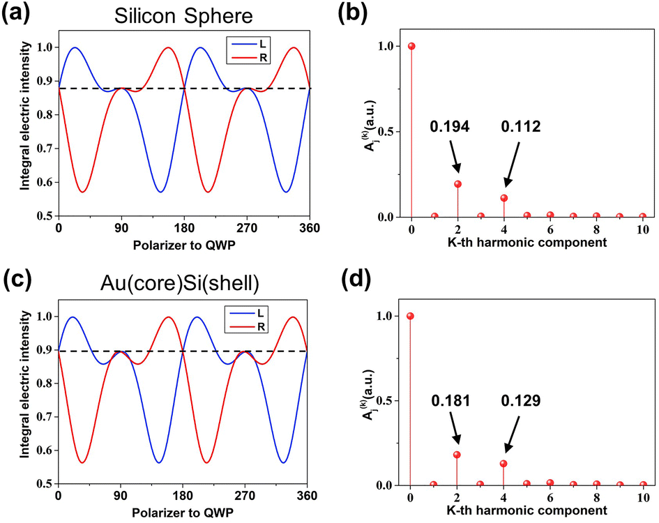 | ||
| Fig. 5 (a and c) Electric intensity of the dipole-excited Bloch surface waves for different incident polarization states from the silicon nanosphere and Au core/silicon shell. (b and d) Fourier analysis of right-side and left-side signals of the silicon nanosphere and Au core/silicon shell, respectively. | ||
To better understand the 2θ- and 4θ-modulations in the recorded signals, we apply Fourier transforms to get them expressed in the following analytical form:
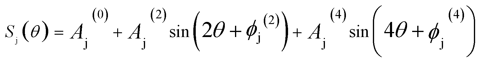 | (6) |
As shown in Fig. 5, the intensity signals consist of harmonic functions of the zeroth, second, and fourth order. The second harmonics is associated with the energy coupling from light into BSWs resulting from the spin-controlled distribution. Moreover, due to the TE-polarized nature of our BSWs (only the magnetic field spins), such a helicity-dependent energy distribution is solely related to the magnetic field of the incident light. It is noted that since here we use a MD coupler, both the second and fourth harmonics should be attributed to magnetic effects. This is different from the literature [17] where an electric coupler was used (see Table S1 of the ESI†).
We see that in Fig. 5(b) the ratio of the second harmonic component to the fourth harmonic is higher than that in Fig. 5(d), which shows that the magnetic optical effect plays a larger role in spin-controlled coupling by using a silicon sphere. (For more details, please refer to Fig. S6(b) of the ESI†.)
Waveguide coupling
Fig. 6(a) shows another photonic platform we use for demonstrating the directional excitation of BSWs mediated by the magnetic SOI of light. The 1D-PC and the light coupler (silicon nanosphere, radius: 0.22 μm) are identical to the ones described in Sec. 4. We shed light on the nanoparticle at an incident angle of 80°. As shown previously, BSWs will be excited on both sides of the nanoparticle. To better pick up the BSW signals from the spurious background of the incoming light beam, we place silicon strip waveguides along the trajectories of BSWs. The silicon waveguides are 10 μm long and have a square cross-section with a side length of 0.44 μm. The center of the silicon waveguides is 7.26 μm away from the center of the nanoparticle, and the angle between the waveguides is set to 60°. As shown in Fig. 6(a), the BSW signal is coupled to a guide mode in the silicon waveguide.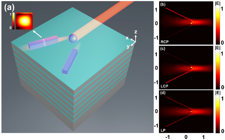 | ||
| Fig. 6 (a) 1D-PC model and the guide mode of the silicon waveguide. (b and c) The field distribution of the structure under the illumination of circularly incident light after two silicon waveguides are placed on the propagation track (the source of b is RCP and that of c is LCP). (d) Field distribution of the structure under the illumination of linearly polarized light. | ||
Given the symmetry of our photonic platform, the optical energies transmitted in the two silicon waveguides are proportional to those coupled from the incident light to the left and right branches of BSWs. The excitation directionality of BSWs can thus be evaluated with the following directionality factor:
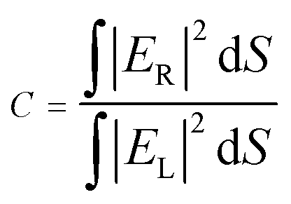 | (7) |
 and the integral is taken over the cross section of the silicon waveguide on the left and right sides, as represented by the subscript “L” and “R” in Fig. 6(a), respectively.
Fig. 6(b) and (c) show the propagating modes excited in the silicon waveguides upon circularly polarized illumination of opposite handedness. They show a strongly unbalanced intensity distribution in the two waveguides with a directionality factor C up to 4.58 in Fig. 6(b). Besides, inversing the handedness of the incident light switches the prevailing side from one to another with a directionality factor C = 1/4.58, manifesting a spin-dependent characteristic of this phenomenon. In contrast, with linearly polarized incident light, the coupled energy is equally distributed (C = 1). According to Section 4 (the energy coupling to BSWs), changing the polarization state of the incident light allows us to tunably control the value of C, which can be utilized to build on-chip light routers.
Conclusions
We present a new demonstration of the magnetic spin–orbit interaction (SOI) of light. We show that a circularly polarized MD source develops a tunable unidirectional coupling of light into TE-polarized BSWs: depending on the helicity of the MD, the optical surface waves were preferentially excited on the left or right side. The underlying physics is the coupling between the longitudinal SAM of the freely propagating photons and the transverse SAM in the evanescent tails of the guided BSWs. The SAM involved in the coupling process is solely described by the rotating magnetic field of light. We further use MD-like nanoparticles as the light-to-BSW converter and silicon stripe waveguides to collect the emerging BSWs. Upon circularly polarized illumination, the ratio of the optical intensities in the left and right waveguides reaches a value up to 4.58. In our study, the magnetic field is not only responsible for the transfer of energy to the BSW, but also controls the directionality of the coupled energy. We thus demonstrate a tunable spin-locking phenomenon characteristic of a pure magnetic effect. Our results open possibilities for the excitation of all TE-polarized guided modes exhibiting directional dependence with the direction of the input circularly polarized light, which offers desirable opportunities for directional switching and polarization sorting by controlling optical flows in ultra-compact architectures. In addition, BSWs can be utilized as local probes to investigate the magnetic polarization properties of light, which also enable the measurement of optical magnetic spin density.15Conflicts of interest
There are no conflicts to declare.Acknowledgements
We acknowledge Dr Mengjia Wang (CNRS, FEMTO-ST Institute UMR 6174, Université Bourgogne Franche-Comté, France) for his helpful discussion. This research was funded in part by the National Natural Science Foundation of China (61775084 and 62075088), the NSAF (U2030103 and U2230111), the Natural Science Foundation of Guangdong Province (2020A1515010791, 2021A0505030036, and 2022A1515110970), and the Fundamental Research Funds for the Central Universities (21622107 and 21622403).References
- S. Zhang, R. Jiang, Y. M. Xie, Q. Ruan, B. Yang, J. Wang and H. Q. Lin, Adv. Mater., 2015, 27, 7432–7439 CrossRef CAS PubMed.
- R. Paniagua-Domínguez, F. López-Tejeira, R. Marqués and J. A. Sánchez-Gil, New J. Phys., 2011, 13, 123017 CrossRef.
- D. R. Smith, J. B. Pendry and M. C. K. Wiltshire, Science, 2004, 305, 788–792 CrossRef CAS PubMed.
- V. M. Shalaev, Nat. Photonics, 2007, 1, 41–48 CrossRef CAS.
- T. H. Taminiau, S. Karaveli, N. F. Van Hulst and R. Zia, Nat. Commun., 2012, 3, 976–979 CrossRef PubMed.
- B. Rolly, B. Bebey, S. Bidault, B. Stout and N. Bonod, Phys. Rev. B: Condens. Matter Mater. Phys., 2012, 85, 245432 CrossRef.
- S. M. Hein and H. Giessen, Phys. Rev. Lett., 2013, 111, 026803 CrossRef PubMed.
- M. Mivelle, T. Grosjean, G. W. Burr, U. C. Fischer and M. F. Garcia-Parajo, ACS Photonics, 2015, 2, 1071–1076 CrossRef CAS.
- E. Devaux, A. Dereux, E. Bourillot, J. C. Weeber, Y. Lacroute and J. P. Goudonnet, Phys. Rev. B: Condens. Matter Mater. Phys., 2000, 62, 10504–10514 CrossRef CAS.
- B. Le Feber, N. Rotenberg, D. M. Beggs and L. Kuipers, Nat. Photonics, 2014, 8, 43–46 CrossRef.
- H. W. Kihm, et al. , Nat. Commun., 2011, 2, 451 CrossRef CAS PubMed.
- T. Grosjean, A. Fahys, M. Suarez, D. Charraut, R. Salut and D. Courjon, J. Microsc., 2008, 229, 354–364 CrossRef CAS PubMed.
- M. Burresi, et al. , Science, 2009, 326, 550–553 CrossRef CAS PubMed.
- M. A. Suarez, T. Grosjean, D. Charraut and D. Courjon, Opt. Commun., 2007, 270, 447–454 CrossRef CAS.
- M. Neugebauer, T. Bauer, A. Aiello and P. Banzer, Phys. Rev. Lett., 2015, 114, 063901 CrossRef CAS PubMed.
- M. F. Picardi, A. Manjavacas, A. V. Zayats and F. J. Rodríguez-Fortuño, Phys. Rev. B, 2017, 95, 245416 CrossRef.
- M. Wang, et al. , Light: Sci. Appl., 2018, 7, 24 CrossRef PubMed.
- J. Petersen, J. Volz and A. Rauschenbeutel, Science, 2014, 346, 67–71 CrossRef CAS PubMed.
- F. J. Rodríguez-Fortuño, I. Barber-Sanz, D. Puerto, A. Griol and A. Martínez, ACS Photonics, 2014, 1, 762–767 CrossRef.
- Y. Lefier and T. Grosjean, Opt. Lett., 2015, 40, 2890–2893 CrossRef PubMed.
- B. Le Feber, N. Rotenberg and L. Kuipers, Nat. Commun., 2015, 6, 6695 CrossRef CAS PubMed.
- Y. Lefier, R. Salut, M. A. Suarez and T. Grosjean, Nano Lett., 2018, 18, 38–42 CrossRef CAS PubMed.
- S. Y. Lee, et al. , Phys. Rev. Lett., 2012, 108, 213907 CrossRef PubMed.
- J. P. B. Mueller, K. Leosson and F. Capasso, Nano Lett., 2014, 14, 5524–5527 CrossRef CAS PubMed.
- Z. Xi, Y. Lu, W. Yu, P. Wang and H. Ming, J. Opt., 2014, 16, 105002 CrossRef.
- J. Lin, et al. , Science, 2013, 340, 331–334 CrossRef CAS PubMed.
- F. J. Rodríguez-fortuño, A. Martínez, G. A. Wurtz and A. V. Zayats, Science, 2013, 340, 328–330 CrossRef PubMed.
- K. Y. Bliokh and F. Nori, Phys. Rev. A: At., Mol., Opt. Phys., 2012, 85, 061801 CrossRef.
- K. Y. Kim, I. M. Lee, J. Kim, J. Jung and B. Lee, Phys. Rev. A: At., Mol., Opt. Phys., 2012, 86, 063805 CrossRef.
- A. I. Kuznetsov, A. E. Miroshnichenko, M. L. Brongersma, Y. S. Kivshar and B. Luk’yanchuk, Science, 2016, 354, 2472 CrossRef PubMed.
- R. Colom, A. Devilez, S. Enoch, B. Stout and N. Bonod, Phys. Rev. A, 2017, 95, 063833 CrossRef.
- A. García-Etxarri, et al , Opt. Express, 2011, 19, 4815–4826 CrossRef PubMed.
- A. I. Kuznetsov, A. E. Miroshnichenko, Y. H. Fu, J. Zhang and B. Luk, Sci. Rep., 2012, 2, 492 CrossRef PubMed.
- A. B. Evlyukhin, et al. , Nano Lett., 2012, 12, 3749–3755 CrossRef CAS PubMed.
- I. S. Sinev, et al. , Laser Photonics Rev., 2017, 11, 1700168 CrossRef.
- W. Liu, J. F. Zhang, B. Lei, H. T. Ma, W. K. Xie and H. J. Hu, Opt. Express, 2014, 22, 16178–16187 CrossRef PubMed.
- W. Liu, A. E. Miroshnichenko, D. N. Neshev and Y. S. Kivshar, ACS Nano, 2012, 6, 5489–5497 CrossRef CAS PubMed.
- F. Shen, N. An, Y. Tao, H. Zhou, Z. Jiang and Z. Guo, Nanophotonics, 2017, 6, 1063–1072 Search PubMed.
- J. J. Kingsley-Smith, M. F. Picardi, L. Wei, A. V. Zayats and F. J. Rodríguez-Fortuño, Phys. Rev. B, 2019, 99, 235410 CrossRef CAS.
- M. F. Picardi, A. V. Zayats and F. J. Rodríguez-Fortuño, Phys. Rev. Lett., 2018, 120, 117402 CrossRef CAS PubMed.
- A. Espinosa-Soria and A. Martínez, IEEE Photonics Technol. Lett., 2016, 28, 1561–1564 CAS.
- M. F. Picardi, A. V. Zayats and F. J. Rodríguez-Fortuño, Laser Photonics Rev., 2019, 13, 1900250 CrossRef.
- F. J. Rodríguez-Fortuño, D. Puerto, A. Griol, L. Bellieres, J. Martí and A. Martínez, Opt. Lett., 2014, 39, 1394–1397 CrossRef PubMed.
- R. Gómez-Medina, J. Nanophotonics, 2011, 5, 053512 CrossRef.
- J. van de Groep and A. Polman, Opt. Express, 2013, 21, 26285–26302 CrossRef CAS PubMed.
- I. Sinev, et al. , Laser Photonics Rev., 2016, 10, 799–806 CrossRef CAS.
- D. L. Markovich, P. Ginzburg, A. K. Samusev, P. A. Belov and A. V. Zayats, Opt. Express, 2014, 22, 10693–10702 CrossRef CAS PubMed.
- T. Feng, Y. Xu, W. Zhang and A. E. Miroshnichenko, Phys. Rev. Lett., 2017, 118, 173901 CrossRef PubMed.
- D. N. Gulkin, et al. , Nanophotonics, 2021, 10, 2939–2947 CrossRef CAS.
Footnote |
| † Electronic supplementary information (ESI) available. See DOI: https://doi.org/10.1039/d2na00899h |
| This journal is © The Royal Society of Chemistry 2023 |