
 Open Access Article
 This Open Access Article is licensed under a Creative Commons Attribution-Non Commercial 3.0 Unported Licence
Electrospun PVDF-based piezoelectric nanofibers: materials, structures, and applications
Mengdi
Zhang
abc,
Chengkun
Liu
 *abc,
Boyu
Li
d,
Yutong
Shen
abc,
Hao
Wang
abc,
Keyu
Ji
abc,
Xue
Mao
abc,
Liang
Wei
abc,
Runjun
Sun
abc and
Fenglei
Zhou
e
*abc,
Boyu
Li
d,
Yutong
Shen
abc,
Hao
Wang
abc,
Keyu
Ji
abc,
Xue
Mao
abc,
Liang
Wei
abc,
Runjun
Sun
abc and
Fenglei
Zhou
e
aSchool of Textile Science and Engineering, Xi’an Polytechnic University, Xi’an, 710048, China. E-mail: liuchengkun@xpu.edu.cn
bKey Laboratory of Functional Textile Material and Product of the Ministry of Education, Xi’an Polytechnic University, Xi’an, 710048, China
cShaanxi College Engineering Research Center of Functional Micro/Nano Textile Materials, Xi’an Polytechnic University, Xi’an, 710048, China
dResearch Institute of Textile and Clothing Industries, Zhongyuan University of Technology, Zhengzhou, 450007, China
eCentre for Medical Image Computing, Department of Medical Physics and Biomedical Engineering, University College London, London WC1E 6BT, UK
First published on 19th January 2023
Abstract
Polyvinylidene fluoride (PVDF) has been considered as a promising piezoelectric material for advanced sensing and energy storage systems because of its high dielectric constant and good electroactive response. Electrospinning is a straightforward, low cost, and scalable technology that can be used to create PVDF-based nanofibers with outstanding piezoelectric characteristics. Herein, we summarize the state-of-the-art progress on the use of filler doping and structural design to enhance the output performance of electrospun PVDF-based piezoelectric fiber films. We divide the fillers into single filler and double fillers and make comments on the effects of various dopant materials on the performance and the underlying mechanism of the PVDF-based piezoelectric fiber film. The effects of highly oriented structures, core–shell structures, and multilayer composite structures on the output properties of PVDF-based piezoelectric nanofibers are discussed in detail. Furthermore, the perspectives and opportunities for PVDF piezoelectric nanofibers in the fields of health care, environmental monitoring, and energy collection are also discussed.
 Mengdi Zhang | Mengdi Zhang received her BS degree from Xi'an Polytechnic University in 2020. She is a master candidate in the School of Textile Science and Materials, Xi'an Polytechnic University. Her current research is on electrospun PVDF-based piezoelectric sensors. |
 Chengkun Liu | Chengkun Liu is currently a professor in the School of Textile Science and Engineering at Xi'an Polytechnic University, Xi'an, China. He received his PhD degree in materials science and engineering from Xi'an Jiaotong University in 2011. He worked as a visiting scholar at the University of Manchester from 2017 to 2018 in the UK. His research focuses on the design and development of flexible sensors for smart wearable products and health, and filtration materials for the environment. |
 Boyu Li | Boyu Li is currently a lecturer in the Textile and Garment Industry of Research Institute at Zhongyuan University of Technology, Zhengzhou, China. He received his PhD degree from Materials Institute of Atomic and Molecular Science at Shaanxi University of Science & Technology in 2021. His research focuses on the design and development of carbon nanofiber materials and their application in flexible electrodes. |
 Liang Wei | Liang Wei is an associate professor in the School of Textile Science and Engineering at Xi'an Polytechnic University of China. He received his MS degree in textile science and engineering from Xi'an Polytechnic University in 2013 and PhD degree in textile science and engineering from Donghua University in 2018, respectively. Dr Wei is experienced in experimental and theoretical research work on multiple jet electrospinning technology and functional nanofibers. His research interests include needleless spinneret design, industrialization production of nanofibers, functional textiles, smart wearable textiles, air filtration materials, oil–water separation materials, and silk fibroin materials. |
 Runjun Sun | Runjun Sun is a professor in the School of Textile Science and Engineering at Xi'an Polytechnic University of China. He received his MS degree in textile science and engineering from Xi'an Polytechnic University in 1999 and PhD degree in textile science and engineering from Donghua University in 2005, respectively. Prof. Sun has long been involved in experimental and evaluation system research work on advanced textile materials. His research interests are the structure and property of textile materials, electromagnetic shielding textiles, and smart textiles. |
 Fenglei Zhou | Fenglei Zhou is a Senior Research Fellow at University College London (UCL), working in the Centre for Medical Image Computing and School of Pharmacy. He obtained a PhD degree from the University of Manchester, UK. From 2010 to 2019, he worked as a research associate and then as a university research fellow in the Centre for Imaging Sciences, University of Manchester. He has participated as a leading research scientist in several large and cross-disciplinary research programmes funded by the EU FP7, UK EPSRC, and Cancer Research UK, in which he pioneered the development of tissue-mimicking imaging phantoms for the validation of diffusion MRI in neurology, heart, and cancer. |
1. Introduction
Piezoelectric materials have been extensively employed to build electronic skins, sensors, energy harvesters, etc. for applications in biomedical engineering, intelligent wearable electronics, and aerospace. Due to fluidity, low density, low cost, flexibility, environmental friendliness, and biocompatibility,1–3 polyvinylidene fluoride (PVDF) as one of the most widely used piezoelectric polymer candidates attracts considerable research interest and has been applied in the fields of energy harvesting,4,5 physiological health monitoring,6,7 and environmental monitoring.8 The PVDF material mainly refers to the homopolymer of vinylidene difluoride or the copolymer of vinylidene difluoride and a small amount of other vinylidene monomers containing fluoride.The primary factor influencing the piezoelectricity of PVDF is its crystalline phase, which has five crystalline varieties: α, β, γ, δ and ε.9,10 Among them, the β phase has a planar zigzag all-trans conformation (TTT) with the –CF2– group and the –CH2– group on either side of the molecular chain, and the dipole moments are placed parallel and perpendicular to the c-axis.11–13 Therefore, this conformation is the most polar conformation with the largest electric dipole moment and the maximum electroactivity.14 Other than the β phase, a recent study reported that the highly mobile oriented ambient fraction (OAF) enables biaxially oriented PVDF films containing pure β crystals to obtain high voltage electrical properties.15 However, most papers on electrospun PVDF fiber films still discuss the influence of the β phase on piezoelectric properties.
Different techniques, including stretching,16 thermal annealing,17 high-voltage electric field polarization,18 as well as filler doping19 and structural design,20 have been utilized to induce dipole alignment to enhance the β-phase proportion in PVDF. The stretching and thermal annealing processes are complicated and only slightly improve the piezoelectric output of pure PVDF when compared to other approaches. Polarization under a high electric field is indeed an effective method to improve the piezoelectric output of PVDF, but the limitation of the polarization direction leads to lack of flexibility in device design, and the preparation procedures are also complicated and time-consuming.21 The methods of producing PVDF piezoelectric materials include tape casting,22 coating methods,23 thermal drawing,24–27 electrospinning,5etc. However, the tape casting, coating, and thermal drawing also need post-treatment (such as high-voltage electric field polarization and thermal annealing) to make PVDF materials have better piezoelectric properties. In contrast, a quick and efficient electrospinning technique can create superfine fibers with diameters ranging from a few nanometers to a few microns and make it easy to incorporate different doping particles into the resultant PVDF nanofibers.28 In addition, strong electric field force during the electrospinning process can facilitate the directional alignment of the –CH2–/–CF2– dipoles and transform the α phase into the β phase leading to the increase of the β-phase content in the PVDF nanofibers.29 Furthermore, the formation of fiber films with different structures through various electrospinning processes can also boost the piezoelectric capabilities of PVDF fiber films.
Recent review articles published by others on the topic have focused on the impact of spinning parameters or one filler doping on the piezoelectric properties of electrospun PVDF films. This review will discuss the improvement of piezoelectric properties of PVDF-based fiber films through material doping and structural modification during the electrospinning process. The performance improvement of PVDF-based piezoelectric fiber films brought by doping various fillers and component combinations is first reviewed from the perspective of adding single and double fillers. Moreover, the impact of structural design on the performance of PVDF-based piezoelectric fiber films is discussed from the perspectives of high-orientation, core–shell, and multilayer structures. Finally, a summary of the current application state of electrospun PVDF-based piezoelectric fiber films is provided (Fig. 1).
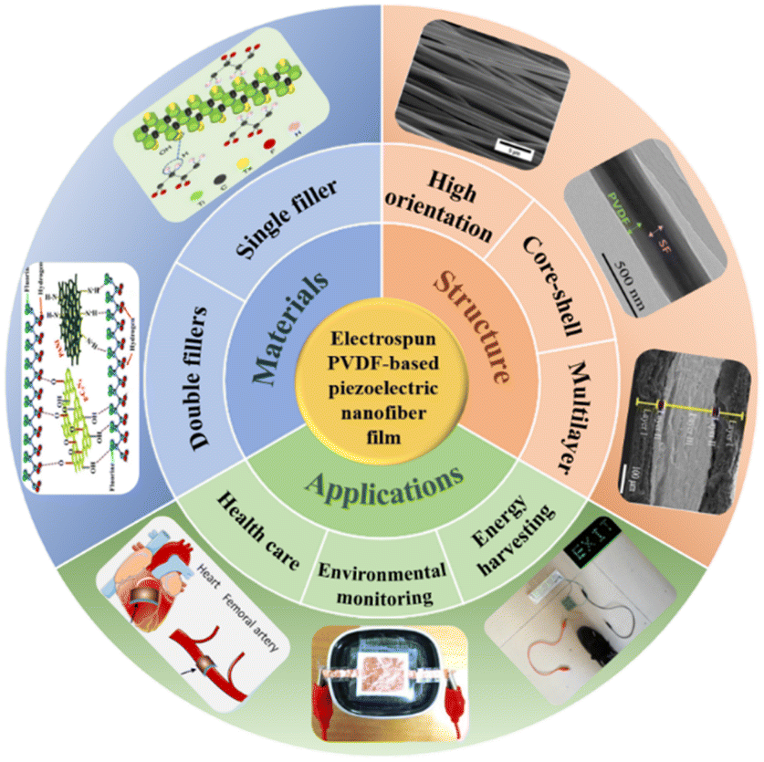 | ||
| Fig. 1 Materials, structures, and applications of electrospun PVDF-based piezoelectric nanofiber films. (Go clockwise from double fillers: reproduced from ref. 131 with permission from the American Chemical Society, copyright 2019. Reproduced from ref. 132 with permission from Elsevier Ltd, copyright 2020. Reproduced from ref. 105 with permission from the MDPI, copyright 2018. Reproduced from ref. 109 with permission from the Chongqing University, copyright 2021. Reproduced from ref. 112 with permission from the Elsevier B.V., copyright 2020. Reproduced from ref. 67 with permission from the Elsevier B.V., copyright 2020. Reproduced from ref. 60 with permission from the American Chemical Society, copyright 2020. Reproduced from ref. 110 with permission from the American Chemical Society, copyright 2019). | ||
2. Doping modification of PVDF nanofiber films
Some researchers tried to improve the piezoelectric properties of electrospun PVDF nanofiber films by altering solution properties, environmental conditions, and spinning parameters. Zhao et al.30 and Lei et al.31 investigated the effects of solution concentration and solvent ratios on the β-phase content of PVDF fiber films, and the results showed that the fiber with a high β-phase content could be produced only when the solution concentration and solvent ratio are in the appropriate range. There were other articles that investigated the effect of PVDF molecular weight size on the piezoelectric properties of PVDF nanofiber films and found that the higher the molecular weight in a certain range, the higher the β-phase content.32 In addition, several studies demonstrated that spinning parameters (applied voltage, feed rate, tip-to-collector distance, or diameter of a needle), ambient temperature, and humidity could also affect β-phase content, and the results showed that their most important role remained to regulate the spinnability of the polymer solution and the morphology of the nanofibers, with the spinning voltage and the tip-to-collector distance exhibiting partial contributions to the formation of the PVDF-β phase.33–35Recently, researchers further improved the piezoelectric properties of PVDF by incorporating specific concentrations of single or double fillers, such as piezoelectric ceramics and conductive particles, into the PVDF matrix to obtain composite nanofiber films.36–42 It's worth noting that too large filler size will significantly increase the solution viscosity, which is not conducive to jet drafting in the electric field.
2.1 Single-filler doping
PZT was the first widely used material due to its high piezoelectric coefficient (d33 = 140 pm V−1).56 It has been reported that electrospun PVDF/PZT nanofibers prepared by doping different concentrations of PZT could possess a higher β-phase content compared to pure PVDF. When PZT was supplied at a concentration of 10 vol%, the maximum effective voltage could reach 79.71 mV at a resistive load of 1 MΩ and 47.2 mV at a non-resistive load.57 In addition, some researchers prepared PZT ceramic particles by combining sol–gel and electrospinning methods, and then electrospun PZT/PVDF nanocomposites containing different volume fractions of PZT were prepared and made into flexible pressure sensors. The findings demonstrated that the crystallinity and β-phase content of PVDF/PZT nanocomposites increased with the increase of PZT volume fraction, and the dielectric constant and piezoelectric coefficient also increased gradually. In comparison to pure PVDF nanofibers with an output voltage of 22 mV at a force of 2.4 N, PVDF/PZT nanocomposites had an output voltage of 184 mV at a force of 2.125 N when the volume fraction of PZT was 0.37 vol%.38 Although PZT is the most widely used and effective piezoelectric material, it is unfavorable to the environment since it includes a lot of lead, which actually causes pollution.58 Therefore, it has led to a growing interest in the use of lead-free piezoelectric ceramic materials as piezoelectric fillers to circumvent these restrictions.
As a highly effective lead-free piezoelectric ceramic material, BaTiO3 (d33 = 130 pm V−1) is widely employed.59 Various PVDF/BaTiO3 nanocomposites were fabricated with the electrospinning technique. The results showed that doping BaTiO3 could increase the β-phase content of composites. The highest output voltage of piezoelectric nanogenerators (PENGs) made of PVDF nanofibers was 360 mV, whereas PENGs made of PVDF/BaTiO3 nanocomposites with a 6% w/w concentration of BaTiO3 had a peak output voltage of 740 mV.60 In another study, the piezoelectric capabilities of electrospun PVDF/BaTiO3 nanocomposites were enhanced by the addition of 5, 10, and 20 wt% of BaTiO3 NPs. β-Phase content could reach 91.0% for PVDF/10 wt% BaTiO3 with a maximum output voltage of 50 V during repetitive bending and releasing at 4 Hz and about 4 V under the frequency of 2 Hz and the pressure of 0.2 N.55 It must also be pointed out that KNN, which has the same perovskite structure as BaTiO3, has also attracted considerable attention. KNN nanorods (NRs) were created through a hydrothermal process and used to create electrospun PVDF/KNN nanofiber films. It was discovered that the maximal output voltage was approximately 17.5 V at an applied force of 0.5 N and a frequency of 10 Hz for the PVDF/3 wt% KNN NRs films with the β-phase content of 78%.61
In lead-free piezoelectric ceramics, ZnO with a good piezoelectric coefficient (d33 = 12.4 pm V−1) also exhibits great application prospects. It has been used in sunscreens with FDA approval, so it is safe for people.62–65 The ZnO nanoparticles (NPs) can be added to PVDF to improve the piezoelectric output performance (Fig. 2a). It was found that ZnO NPs can operate as nucleating agents to produce strong interactions on the contact surface with PVDF, and increase the β-phase content of PVDF.66 The peak output voltage and current of the PVDF/ZnO device were 4.4 V and 45 μA, while those of the pure PVDF device were only 1.7 V and 160 nA at a force of 5 N and a frequency of 0.4 Hz. In addition to the addition of ZnO NPs, ZnO nanowires (NWs) could also be added into electrospun PVDF and nylon 11 nanofibers to develop innovative piezoelectric nanofiber materials. Both PVDF/ZnO NWs and nylon/ZnO NWs were processed into triboelectric nanogenerators (TENGs).67 The addition of ZnO NWs made the β-phase content increase from 61.3% to 73.4%. The maximum open-circuit voltage of the nanogenerator was 330 V. ZnO NRs could also be added as a useful filler to enhance the piezoelectric capabilities of PVDF fiber films with an open-circuit voltage of roughly 85 V and a short-circuit current of roughly 2.2 μA. The β-phase content of PVDF/ZnO NRs fibrous films could reach 90.7%.68
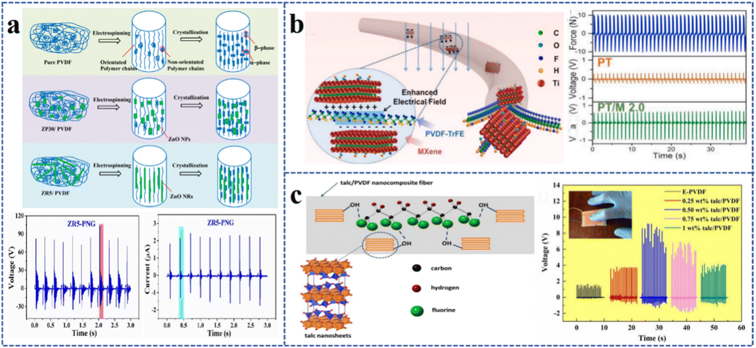 | ||
| Fig. 2 Electrospun PVDF-based single-filler nanofiber films: (a) schematic of the proposed mechanism for the electrospinning of pure PVDF, ZP30/PVDF, ZR5/PVDF composite fibers. Reproduced from ref. 68 with permission from the American Chemical Society, copyright 2019. (b) Three-dimensional molecular model of the β-phase formation during the electrospinning process. Reproduced from ref. 77 with permission from the Elsevier Ltd, copyright 2020. (c) Interaction mechanism between talc nanosheets and PVDF chain in electrospinning nanocomposite fabric. Reproduced from ref. 87 with permission from the Royal Society of Chemistry, copyright 2020. | ||
Currently, organic piezoelectric fillers are also used in electrospun PVDF nanofiber films. There was a study which reported the preparation of PVDF/PAN composite nanofiber films through electrospinning. The results showed that the β-phase content, fracture strength, and elongation of the film were 83.4%, 7 MPa and 26%, respectively, which were dominant and could be used to prepare PENGs.69 When the applied force was 1 N, the PENG had a stable output voltage of 1.3 V. Cellulose nanocrystals (CNCs) as an organic piezoelectric nanofiller can also be used to prepare PVDF/CNC composite fibers. Researchers explored the influence of doping different concentrations of CNCs on the piezoelectric output performance of PVDF fiber films. It was found that when the CNC concentration was 2 wt%, the highest β-phase content of 89.96% could be obtained with the output voltage of 60 V.70
Because graphene and carbon nanotubes (CNTs) are carbon materials with excellent electrical conductivity, the β-phase content and the charge transfer capability were found to be simultaneously increased for PVDF nanofiber films doped with them.71,72 It was shown that multi-walled CNTs (MWCNTs) could act as a nucleation in the crystallization process facilitating the conversion of the α phase to the β phase and cause charge accumulation at the interface when they were used.37 Therefore, high β-phase content of PVDF films could be acquired by adding MWCNTs. It was found that the β-phase content of the PVDF/5 wt% MWCNT nanofiber film was 68.4% and could produce a maximum piezoelectric voltage of up to 6 V at a mechanical bending frequency of 0.8 Hz. However, the β-phase content and piezoelectric voltage of the pure PVDF nanofiber film were only 54.8% and 2 V.73 There has been only limited study on CNTs as a single-filler doping in recent years; extensive studies are focusing on graphene as a candidate. Researchers prepared graphene oxide (GO) and reduced graphene oxide (rGO) materials through Hummers' method and then made them into PVDF/GO and PVDF/rGO composite nanofibers by electrospinning.74 According to the findings, the open-circuit voltage was found to increase from 0.50 V to 0.65 V and 4.38 V by respectively adding 0.8 wt% GO and rGO to PVDF at a finger tap of 5 Hz. Another researcher increased the content of GO or rGO in the PVDF fiber film to 2 wt%, and the β-phase contents of PVDF/GO and PVDF/rGO were both increased to about 87%.75 The short-circuit current and open-circuit voltage of the PVDF/GO fiber film were 200 nA and 1.5 V, respectively. Due to the higher conductivity of rGO, the short-circuit current and open-circuit voltage of the PVDF/rGO fiber film were 700 nA and 16 V, respectively, which were 20 times higher than those for the pure PVDF film. Therefore, rGO has a better impact on the piezoelectric output augmentation of PVDF fiber films.
MXene, rich in a large number of –OH groups can yield hydrogen bonding interactions with –CH2– in PVDF chains and facilitate the formation of the β phase in PVDF (Fig. 2b).76 The oriented PVDF-TrFE/MXene fiber film was prepared by electrospinning, and the results showed that when the addition of MXene was 2 wt%, the output voltage of the PVDF-TrFE/MXene composite film was 1.58 V at a frequency of 1 Hz and a force of 20 N, which was 3 times that of the pure PVDF-TrFE fiber film under the same mechanical stimulation.77
The β-phase content of PVDF nanofiber films could also be increased by mixing salt compounds with metal ions into the PVDF matrix.78–80 It was found that the piezoelectric qualities of PVDF fiber films could be substantially boosted by doping silver nitrate (AgNO3).81 Under a shaker power unit with a frequency of 500 Hz and an amplitude of 5 mm, the output voltage was increased from 0.27 V to 2 V by adding 0.3 wt% AgNO3. Adding BiCl3 to PVDF nanofiber composite films could also enhance their β-phase content. The PVDF/BiCl3 composite film PENG obtained an output voltage of 1.1 V under vertical vibration conditions, which was 4.76 times higher than that of the pure PVDF film PENG.82 According to a study, lithium chloride (LiCl) could also contribute to the increase of the amount of β phase for the electrospun PVDF nanofibers.83 The β-phase content of PVDF nanofiber films increased from 84% to 93.6% when LiCl was added at 0.00133 wt%. The piezoelectric output signal of the fiber films was tested by selecting 12 g spheres dropped from a height of 30 cm, and the results showed that the peak output voltages of PVDF/LiCl and PVDF fiber films were 8 V and 1.89 V, respectively.
In addition, clay materials were frequently used as fillers.84–86 Mg3Si4O10(OH)2 (Talc), a clay material, is rich in –OH group and can interact with –CF2 group of the PVDF matrix through hydrogen bonds, thus contributing to the orientation of dipoles in the PVDF matrix and the formation of the β phase (Fig. 2c). The β-phase content of the PVDF composite nanofiber film with 0.5 wt% Talc reached 89.6%, higher than that of pure PVDF (60.4%). The maximum output voltage of the composite film was 9.1 V, whereas the output voltage of pure PVDF was only 1.6 V at a finger tap force of about 3.8 N.87
Organic polymers and their derivatives with C![[double bond, length as m-dash]](https://www.rsc.org/images/entities/char_e001.gif) O or –NH2 groups can interact with –CH2 and –CF2 groups in PVDF to form hydrogen bonds, thus increasing the β-phase content.88 It was found that the β phase of electrospun PVDF/TPU nanofibers was formed during the chemical interaction between the –CF2 group of PVDF and the –NH2 group in TPU.89 Furthermore, intrinsically conducting polymers (ICPs) could be spun as a filler with PVDF to increase the efficiency of charge transfer and the piezoelectric responsiveness of PVDF.90,91 Polycarbazole (PCZ) and polyaniline (PANI) were added respectively to prepare electrospun PVDF/PCZ and PVDF/PANI fiber films. Studies have shown that the PVDF/PCZ fiber film had a higher β-phase content than PVDF/PANI and pure PVDF fiber films.92 The open-circuit output voltage of PVDF/PCZ fiber film was 2 V under the parameters of effective area of 2.7 cm × 2.3 cm, pressure of 0.24 MPa, and frequency of 4 Hz, but that of the pure PVDF nanofiber was only 0.35 V.
O or –NH2 groups can interact with –CH2 and –CF2 groups in PVDF to form hydrogen bonds, thus increasing the β-phase content.88 It was found that the β phase of electrospun PVDF/TPU nanofibers was formed during the chemical interaction between the –CF2 group of PVDF and the –NH2 group in TPU.89 Furthermore, intrinsically conducting polymers (ICPs) could be spun as a filler with PVDF to increase the efficiency of charge transfer and the piezoelectric responsiveness of PVDF.90,91 Polycarbazole (PCZ) and polyaniline (PANI) were added respectively to prepare electrospun PVDF/PCZ and PVDF/PANI fiber films. Studies have shown that the PVDF/PCZ fiber film had a higher β-phase content than PVDF/PANI and pure PVDF fiber films.92 The open-circuit output voltage of PVDF/PCZ fiber film was 2 V under the parameters of effective area of 2.7 cm × 2.3 cm, pressure of 0.24 MPa, and frequency of 4 Hz, but that of the pure PVDF nanofiber was only 0.35 V.
For the single-filler doping, some researchers have chosen fillers that can act as nucleating agents to promote the enhancement of β-phase content in PVDF fiber films, while others have selected fillers with excellent electrical conductivity to promote charge transfer. For better results, researchers have explored the means of double-filler doping to play the synergistic effect of the above two aspects.
2.2 Double-filler doping
There are a variety of double-filler combination methods, and each combination method has a unique set of benefits compared with single-filler doping. The first is to use two piezoelectric materials to enhance piezoelectric capabilities. The second is to utilize conductive fillers to more quickly and effectively transfer the charge from the inside of the fiber film to its surface leading to an increase in output voltage. The third is to use other materials to modify the piezoelectric materials and play the role of interface modification or ion binding to improve the piezoelectric properties.The addition of BaTiO3 and ZnO NRs in PVDF solution can facilitate the linking of polymer molecular chains to the crystalline β-phase due to contact between PVDF, BaTiO3, and ZnO NRs to improve the formation of the β phase in electrospun nanofibers.93 The results demonstrated that the piezoelectric output of the PVDF/BaTiO3/ZnO composite film increased to 12 V at an applied force of 1.5 N. In another study on the electrospun PVDF/KNN/ZnO composite film, its output voltage was found to be higher than that of PVDF/KNN or PVDF/ZnO (Fig. 3a).94 The PVDF/3% KNN/2% ZnO fiber film had the highest β-phase content of 94% and the output voltage and current of the nanogenerator made of it were 25 V and 1.81 μA in a finger tapping mode and 8.31 V and 5 μA at a constant pressure of 1 kPa. Consequently, the piezoelectric capabilities of PVDF/KNN/ZnO nanogenerators were significantly improved by the synergistic impact of KNN and ZnO NRs in the PVDF polymer matrix.
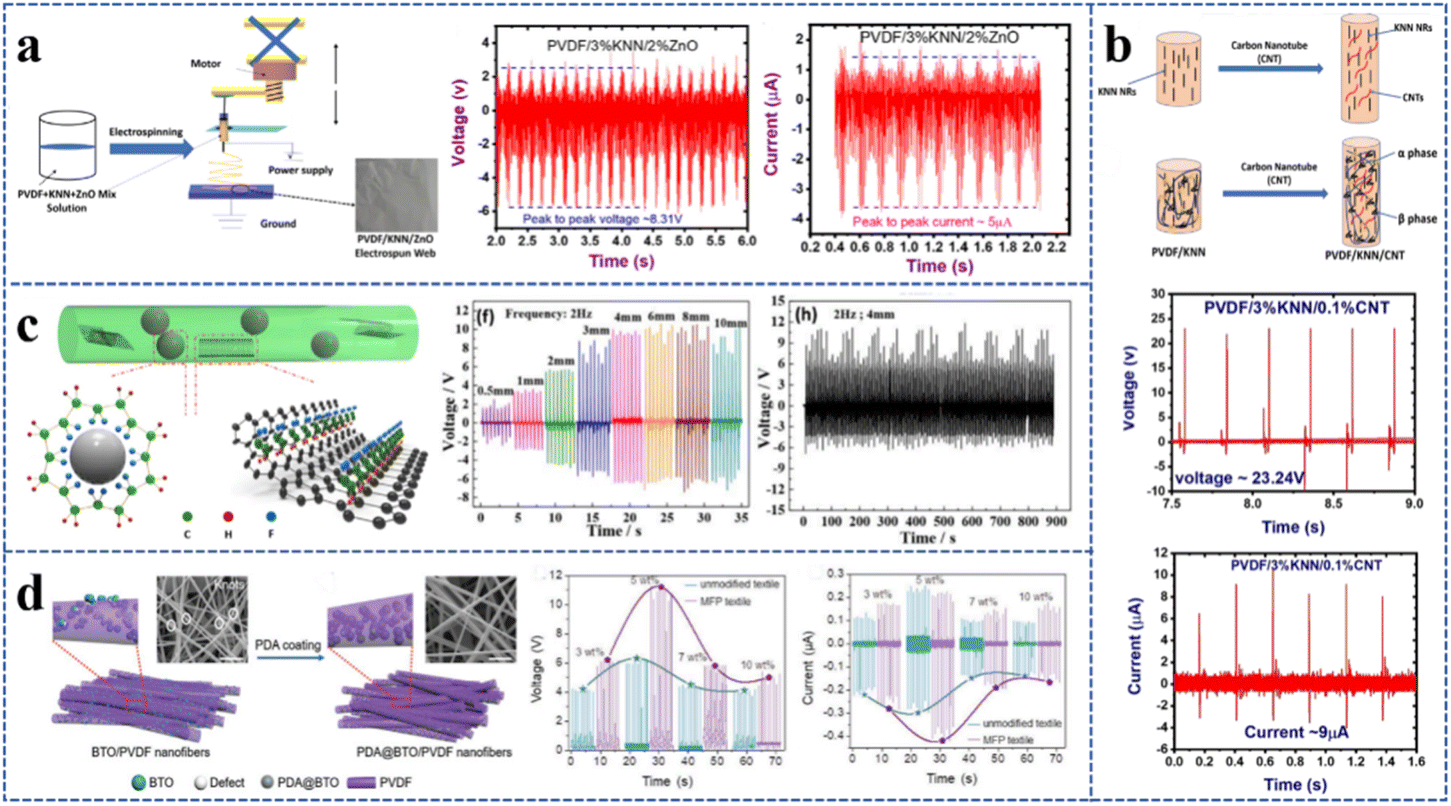 | ||
| Fig. 3 Electrospun PVDF-based nanofiber films with two fillers: (a) fabrication of electrospun PVDF/KNN/ZnO web. Reproduced from ref. 94 with permission from John Wiley & Sons, Inc., copyright 2020. (b) Mechanical stretching effect of the electrospun fiber in the presence of CNTs and β-nucleating effect of the CNTs in the PVDF polymer matrix. Reproduced from ref. 96 with permission from the Royal Society of Chemistry, copyright 2020. (c) The mechanism diagram of β phase formation on BaTiO3 NPs and graphene nanosheets in the nanocomposite fiber. Reproduced from ref. 98 with permission from Elsevier Ltd, copyright 2018. (d) Comparison between unmodified and modified electrospun fibers via dopamine coating. Scale bar is 1 μm. Reproduced from ref. 101 with permission from John Wiley & Sons, Inc., copyright 2021. | ||
The addition of CNTs as a conductive material into the PVDF/KNN spinning solution enhanced the conductivity of the polymer jet, leading to a higher β-phase content in the hybrid nanocomposite (Fig. 3b).96 The PVDF/KNN fiber nanogenerator produced a voltage of about 17.5 V and a current of about 0.522 μA by doping 3 wt% KNN NRs in PVDF. When 0.1 wt% CNTs were further doped into PVDF/KNN solution to spin PVDF/KNN/CNT composite nanofiber films, the output voltage could be up to about 23.24 V and the current was about 9 μA when tapped by a finger.
Graphene with an excellent electrical conductivity has also been used by combining with piezoelectric materials to prepare composite nanofiber films. Graphene-ZnO (G-ZnO) nanocomposites were synthesized by a hydrothermal method and then added to the PVDF nanofibers through electrospinning. The piezoelectric capability of PVDF/G-ZnO nanofiber composites was improved due to the higher β-phase content (62.36%) compared with that of PVDF/ZnO (56.22%) and pure PVDF (51.08%).97 The PVDF/G-ZnO nanofiber composites had an average output voltage of 840 mV under an external force of 1 N, which was superior to PVDF/ZnO (710 mV) and pure PVDF (640 mV) nanofibers. Graphene nanosheets and BaTiO3 NPs can also be co-incorporated into PVDF to prepare PVDF/graphene/BaTiO3 composite nanofiber films. When the contents of graphene and BaTiO3 were 15 wt% and 0.15 wt%, the β-phase content of PVDF/graphene/BaTiO3 composite nanofiber film could reach 91.1%. The open-circuit voltage and power were respectively up to 11 V and 4.1 μW at a loading frequency of 2 Hz and a deformation of 4 mm. Under 1800 cycles in the durability test, there was no appreciable drop of open-circuit voltage. Furthermore, the PENG made from the composite film produced a peak voltage of up to 112 V when pressed by a finger, which was enough to power an electric meter or illuminate 15 LEDs. Therefore, the combination of graphene nanosheets with BaTiO3 NPs was demonstrated to enhance the piezoelectric capabilities of composite nanofibers (Fig. 3c).98
Inspired by biological connective tissue, a thin interfacial connection based on polydopamine (PDA) was created between BaTiO3 NPs and the PVDF matrix.101 The PDA coating was not only conducive to the improvement of the bonding force of BaTiO3 and PVDF but also could enable the composite fiber to obtain a favorable smooth surface morphology (Fig. 3d), which was advantageous to the load transfer in the PDA@BaTiO3/PVDF composite fiber and the generation of a stronger electromechanical coupling effect, thus obtaining a higher piezoelectric response. The findings demonstrated that the piezoelectric performance increased by 47% when 3.02 wt% PDA was doped. The output voltage of the PDA-modified device was around 11 V, whereas that of the unmodified device was around 6.5 V when the mass fraction of BaTiO3 was 5 wt%.
PVDF, PVDF/ZnO, PVDF/BiCl3, and PVDF/BiCl3/ZnO nanofibers were separately spun in order to study the impact of ZnO and BiCl3 on the piezoelectric capabilities of PVDF nanofiber films.102 The findings showed that the β-phase content of PVDF/BiCl3/ZnO nanofiber films was up to 92%, and those of pure PVDF, PVDF/BiCl3, and PVDF/ZnO were 76%, 84%, and 88%, respectively. The active interaction between the surface charges of ZnO NPs and the ionized ions produced by BiCl3 was responsible for the high β-phase content of PVDF/BiCl3/ZnO nanofiber films. The open-circuit voltage and short-circuit current of the PVDF/BiCl3/ZnO nanofiber films were around 12 V and 80 nA, which were obviously higher than the values of 4 V and 20 nA for pure PVDF ones.
As mentioned above, researchers have attempted to improve the piezoelectric performance of PVDF fiber films by double-filler doping, aiming at a breakthrough in the functionality of PVDF-based piezoelectric devices just with a single filler. It is clear from the literature that researchers are paying more attention to the combination of piezoelectric and conductive materials, or piezoelectric and other materials. However, investigations on dual piezoelectric fillers have not been carried out in great numbers.
The comparison of β-phase contents and output voltages of some electrospun filler-modified PVDF nanofiber films mentioned above under different pressure conditions is shown in Table 1.
| Filling types | Nanofiber films | β-Phase contents (%) | Pressure conditions | Output voltages (V) | References |
|---|---|---|---|---|---|
| Single filler | PVDF/PZT | — | 2.125 N | 0.184 | 38 |
| PVDF/BaTiO3 | 91.0 | 0.2 N 2 Hz | ∼4 | 60 | |
| PVDF/KNN | 78 | 0.5 N 10 Hz | ∼17 | 61 | |
| PVDF/ZnO | 80.2 | 5 N 0.4 Hz | 4.4 | 66 | |
| PVDF/PAN | 83.4 | 1 N | 1.3 | 69 | |
| PVDF/CNCs | 89.96 | — | 60 | 70 | |
| PVDF/CNTs | 68.4 | 0.8 Hz | 6 | 73 | |
| PVDF/GO | 87 | — | 1.5 | 75 | |
| PVDF/rGO | 87 | — | 16 | 75 | |
| PVDF-TrFE/MXene | — | 20 N 1 Hz | 1.58 | 77 | |
| PVDF/AgNO3 | — | 500 Hz 5 mm | 2.0 | 81 | |
| PVDF/BiCl3 | 85.7 | — | 1.1 | 82 | |
| PVDF/LiCl | 93.6 | 12 g 30 cm | 8 | 83 | |
| PVDF/Talc | 89.6 | ∼3.8 N | 9.1 | 87 | |
| PVDF/PCZ | — | 0.24 MPa 4 Hz | 2 | 92 | |
| Double fillers | PVDF/ZnO/BaTiO3 | — | 1.5 N | 12 | 93 |
| PVDF/KNN/ZnO | 94 | 1 kPa | 8.31 | 94 | |
| PVDF/KNN/CNTs | 84 | 1 kPa | 12 | 96 | |
| PVDF/G-ZnO | 62.36 | 1 N | 0.84 | 97 | |
| PVDF/BaTiO3/graphene | 91.1 | 2 Hz | 11 | 98 | |
| PDA@ BaTiO3/PVDF | 63.0 | 3 N | ∼13 | 101 | |
| PVDF/BiCl3/ZnO | 92 | 0.2 N | 12 | 102 |
3. Structural modification of PVDF nanofiber films
The output performance of the electrospun PVDF piezoelectric nanofiber film can also be improved by modifying its structures. Nanofibers with a highly oriented structure can be obtained by changing the receiving device of the electrospinning setups. Coaxial nanofibers can be obtained by changing the needle form of electrospinning. Multilayer nanofibers can be produced by changing the spinning method or combining it with other techniques.3.1 Highly oriented structure
By changing receiving devices, the microscopic morphology of electrospun PVDF fiber films can be altered. Disordered nanofibers are usually collected by using flat-plate receiving devices, while oriented nanofibers can be collected by using high-speed drums, spinning discs, Helmholtz coils, twin rod collectors, and stepped collecting devices. The output performance of PVDF fiber films is proven to be affected by the orientation degree of nanofibers. The higher the orientation degree of the fibers, the more rapid the charge transfer in the axial direction of the fibers and the higher the piezoelectric output.One of the most popular collectors for gathering oriented electrospun fibers is the high-speed rotating drum.103 It was discovered that the output voltage of oriented PVDF fiber films obtained at a drum speed of 1500 rpm rose from 0.8 V to 3.6 V as the acceleration amplitude of the shaker increased from 2.0 g to 3.0 g (Fig. 4a).104 When the drum speed was increased to 4000 rpm, highly oriented PVDF-TrFE nanofiber films could be formed. The FTIR results showed that the β-phase content of the fiber film was close to 85%. The prepared sensor had good linearity in the low-pressure region (0.1–1 Pa) with a voltage response of 1 V at 1 Hz under a cyclic bending test.21 Another study further tested the charge output capacity of the oriented nanofiber film by applying two tensile forces (0° parallel and 90° perpendicular to the oriented fiber).105 The charge output in the 0° direction was 10 pC, higher than that in the 90° direction, demonstrating improved directional strain sensing capabilities for the oriented PVDF-TrFE nanofiber mats (Fig. 4b). The piezoelectric charge output of the nanofiber film along the fiber orientation direction parallel to the cantilever beam was approximately 5 times higher than that along the vertical directions when two PVDF-TrFE nanofiber films of the same size were embedded in the vibrated PDMS cantilever beam, which further indicated that well-aligned PVDF-TrFE nanofiber films had outstanding directional strain sensing capabilities and the strain sensors made of them exhibited better strain sensitivity than those based on randomly oriented nanofibers.
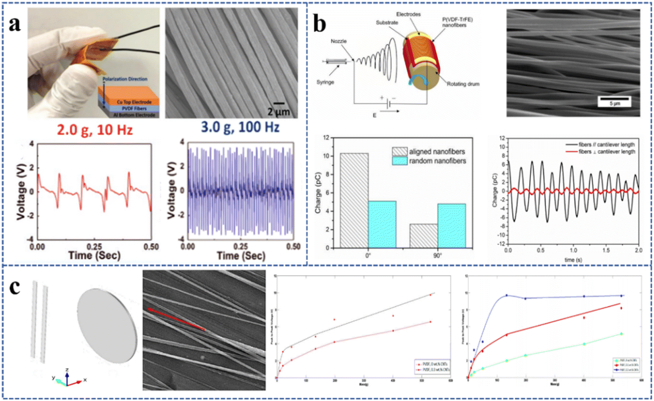 | ||
| Fig. 4 Electrospun highly oriented PVDF-based nanofiber films: (a) piezoelectric properties of electrospun oriented PVDF fiber film. Reproduced from ref. 104 with permission from John Wiley & Sons, Inc., copyright 2020. (b) Aligned PVDF-TrFE nanofibers for enhanced piezoelectric directional strain sensing. Reproduced from ref. 105 with permission from the MDPI, copyright 2018. (c) Aligned electrospun PVDF/CNT nanofibers collected by a two-bar system. Reproduced from ref. 106 with permission from the MDPI, copyright 2018. | ||
Oriented nanofibers have also been obtained in other ways. For example, a two-bar system was used to collect oriented PVDF/CNT nanofibers.106 The results revealed that the β-phase content of random PVDF/CNT nanofibers was 74.2% when 0.3 wt% CNTs were added, but that of the highly oriented PVDF/CNT nanofibers reached 86%. When a pressure of up to 100 g by weight was applied, the sensitivity of random PVDF/CNT nanofibers was 8.8 mV g−1, whereas that of strongly oriented PVDF/CNT nanofibers was enhanced to 73.8 mV g−1 (Fig. 4c).
3.2 Core–shell structures
At the fiber level, core–shell structured PVDF nanofibers could be fabricated via coaxial electrospinning. In coaxial electrospinning, the spinneret consists of two concentric aligned nozzles, and the core and sheath precursor solutions are respectively fed through the inner nozzle and the outer nozzle at a controlled rate. This structure has been reported to contribute to the increase in the output voltage of fibers.One way the researchers designed the core–shell structure was to introduce nano fillers in the core–shell PVDF spinning solution. BaTiO3 NPs and GO nanosheets were jointly introduced in PVDF, with PVDF/BaTiO3 and PVDF/GO solution as the core and skin layers, respectively. The resultant core–shell structured nanofibers were found to have greatly improved piezoelectric characteristics (Fig. 5a). In comparison to pure PVDF nanofibers, the output voltage of the core–shell structured nanofibers increased from 0.75 V to 2.5 V and the current increased from 4.6 nA to 10.5 nA at a frequency of 2 Hz and an applied external force of 10 N.107 In another study, (PVDF-HFP)-TiO2/PVDF-ZnO core–shell nanofibers were prepared by adding TiO2 and ZnO NPs to PVDF-HFP and PVDF, respectively.108 The maximum output voltage of PVDF-HFP/PVDF core–shell nanofibers without fillers was 1.75 V at 45 Hz, while that of the (PVDF-HFP)-TiO2/PVDF core–shell nanofibers was slightly increased to 2 V, the (PVDF-HFP)/PVDF-ZnO core–shell nanofibers rose to 5.5 V, and the output voltage of the composite film material containing both TiO2 and ZnO reached 14 V (Fig. 5b).
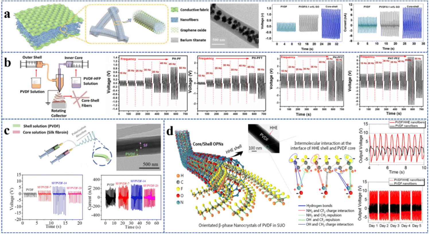 | ||
| Fig. 5 Electrospun core–shell structured PVDF-based nanofiber films: (a) PVDF-BaTiO3/PVDF-GO piezoelectric nanofiber film. Reproduced from ref. 107 with permission from Elsevier Ltd, copyright 2020. (b) Piezoelectric properties of (PVDF-HFP)-TiO2/PVDF-ZnO nanofiber film. Reproduced from ref. 108 with permission from the MDPI, copyright 2020. (c) PVDF/SF coaxial piezoelectric nanofiber film. Reproduced from ref. 109 with permission from Chongqing University, copyright 2021. (d) PVDF/HHE coaxial piezoelectric nanofiber film. Reproduced from ref. 110 with permission from the American Chemical Society, copyright 2019. | ||
Another way is that some kinds of other polymer solutions are combined with PVDF solution to form a fiber with a core–shell structure. The formation of β phase in the core–shell structure was facilitated by the intermolecular contact between the shell polymer layer and the core PVDF layer, hence increasing the content of β phase in PVDF. Core–shell structured piezoelectric nanofibers were obtained by coaxial electrospinning of SF and PVDF solutions as shown in Fig. 5c.109 When the SF content was 14 wt%, the β-phase content reached 66%. Compared with the output voltage and current of 2.5 V and 190 nA for pure PVDF nanofiber devices, those for PVDF/SF nanofiber devices were 16.5 V and 290 nA showing a significant increase. This nanofiber film was also quite flexible. Another study improved the stability of the β phase in PVDF by wrapping hydroxylamine hydrochloride (HHE) over the outer surface of PVDF nanofibers to form a thin shell.110 The molecular interactions of the –NH2 group in HHE and the –CF2 group in PVDF increased the β-phase content of PVDF/HHE piezoelectric nanofibers to 96% at the HHE concentration of 1.0 wt%, and the output voltage measured at a micropressure of 1 kPa and a low frequency of 1.5 Hz was 18 V, which was 3.6 times that of the pure PVDF nanofiber film (Fig. 5d). The PVDF/HHE sensor demonstrated outstanding wear resistance throughout 5 days of nonstop cyclic compression (28![[thin space (1/6-em)]](https://www.rsc.org/images/entities/char_2009.gif) 000 cycles), with the output voltage remaining nearly constant at 18 V, but that of the pure PVDF sensor gradually declined from 5.1 V to 3.5 V.
000 cycles), with the output voltage remaining nearly constant at 18 V, but that of the pure PVDF sensor gradually declined from 5.1 V to 3.5 V.
3.3 Multilayer composite structure
Utilizing the top outside layers of the multilayer composite fiber film as electrode materials is one purpose for the design of a multilayer composite structure. Another aim is to increase the total dipole moment for a higher piezoelectric output by increasing the number of layers of multilayer composite fiber films.By combining the electrospun PVDF fiber film with the fiber film generated in another way (e.g., vapor phase polymerization, electrospraying, and tape casting), a multilayer composite structure can be created. It was found that electrospinning and vapor phase polymerization could be combined to improve the output performance of all-organic piezoelectric nanogenerators (OPNG). Vapor phase polymerization was utilized to deposit poly(3,4-ethylenedioxythiophene) (PEDOT) on the surface of electrospun PVDF nanofibers to prepare PEDOT-coated PVDF as the electrode and auxiliary piezoelectric layer. A layered structure of PEDOT-coated PVDF/PVDF/PEDOT-coated PVDF was created, with pure PVDF nanofibers sandwiched in the middle as the primary piezoelectric layer (Fig. 6a). The OPNG displayed an output voltage of roughly 48 V when a pressure of 8.3 kPa was applied. Over 21000 cycles of continuous mechanical shock were used in the 6-month-long fatigue testing, which revealed a steady piezoelectric output and a good durability.111 In addition, electrospinning, vapor phase polymerization, and electrospraying techniques could be combined to prepare a multilayer structure. Researchers created a high-performance nanogenerator made of an electrospun PVDF nanofiber layer in the middle, polypyrrole (PPy)/PVDF nanofibers through vapor phase polymerization of the pyrrole monomer on the surface of electrospun PVDF nanofibers as the top/bottom electrodes, and two layers of electrosprayed bromine lead cesium(CsPbBr3)@PVDF microbeads inserted between them (Fig. 6b).112 According to the piezoelectric test results, the nanogenerator was found to be capable to detect weak pressures as low as 7.4 Pa and had a high open-circuit voltage of 10.3 V and a short-circuit current density of 1.29 μA cm−2.
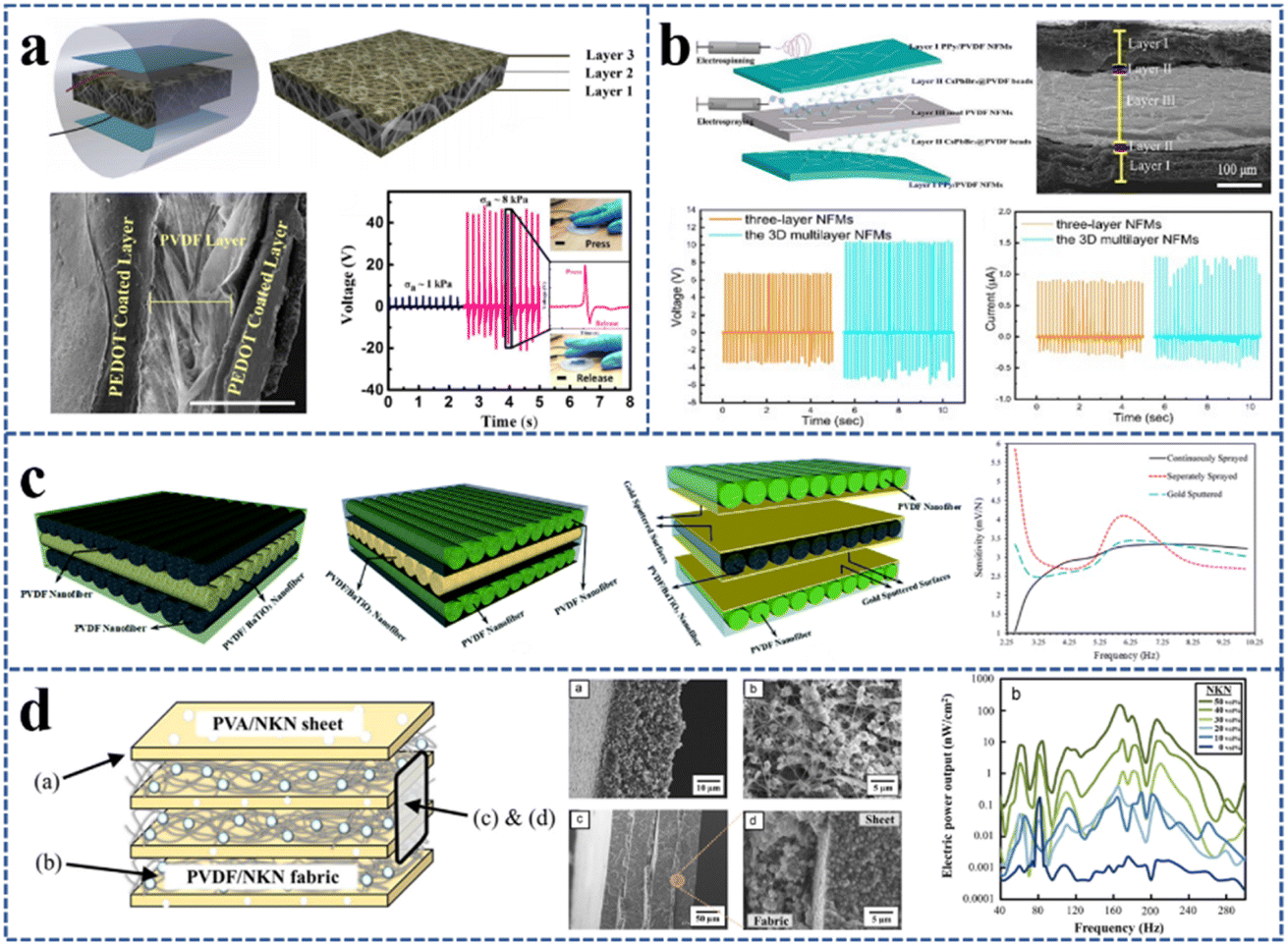 | ||
| Fig. 6 Electrospun PVDF-based nanofiber films with a multilayer structure: (a) multilayer assembled electrospun nanofiber mats and their piezoelectric properties. Reproduced from ref. 111 with permission from the American Chemical Society, copyright 2018. (b) Multilayer assembly of electrospun/electrosprayed PVDF-based nanofibers and beads. Reproduced from ref. 112 with permission from Elsevier B.V., copyright 2020. (c) Flexible PVDF/BaTiO3 hybrid-structure pressure sensor. Reproduced from ref. 113 with permission from the Royal Society of Chemistry, copyright 2020. (d) PVDF-based multilayer composite. Reproduced from ref. 114 with permission from Elsevier B.V., copyright 2015. | ||
The multilayer composite structure can also be formed by the superposition of electrospun PVDF fiber films doped with different fillers or the superposition of electrospun PVDF fiber films with other electrospun fiber films. For instance, piezoelectric sensors were fabricated from three types of triple-layer electrospun PVDF/PVDF-BaTiO3/PVDF nanofiber composites, which were created by sandwiching two PVDF fiber layers with a PVDF/BaTiO3 fiber layer (Fig. 6c)113 in which, the second combination had the best varistor performance with a sensitivity of 6 mV N−1. Besides, electrospun PVDF fiber films can be stacked with other electrospun fiber films to improve the piezoelectric output. By alternatively laminating electrospun PVDF/NKN fiber films with PVA/NKN sheets created by tape casting, researchers have created multilayer composites for energy harvesting (Fig. 6d). The greatest power output of the energy harvester was measured to be 145 nW cm−2 in a vibration cycle of 170 Hz.114
Based on the above research studies, it can be seen that the output performance of the PVDF piezoelectric nanofiber film can be improved through structural design. PVDF fiber films with a highly oriented structure, coaxial structure or multilayer composite structure have higher piezoelectric output than those with a disordered structure. Moreover, some doped fillers can combine with the structure to play a synergistic role in the performance of PVDF piezoelectric fiber films.
4. Applications
4.1 Health care
PVDF nanofiber films can be used to make biocompatible and flexible implantable sensors to be implanted in animals to detect minute internal pressures and respond to the beating and contraction of the heart and blood vessels for pathological detection,115–117 or to promote wound healing using the generated electrical stimulation signals.118,119 Similarly, external detection sensors prepared from PVDF fiber films can be used for health monitoring of pressure changes generated by human movement in daily life, such as breathing, foot pressure, and flexion of fingers, elbow, and neck.120 Compared with sensors for monitoring human motion, implantable sensors and sensors for detecting tiny pressure such as pulse need higher sensitivity to achieve detection function.Regarding implantable sensors, the PVDF/HHE sensor implanted in experimental pigs maintained its hypersensitivity, allowing real-time and accurate detection of internal micro-pressure changes outside the cardiovascular wall (Fig. 7a), as well as simultaneous output of piezoelectric signals reflecting changes in cardiovascular elasticity, cardiac impulse, and thrombosis.110 The researchers subsequently implanted a flexible PVDF/DA piezoelectric sensor into mice and achieved exceptional sensitivity and accuracy in detecting weak physiological mechanical impulses brought on by diaphragmatic motion and blood pulsation, which were crucial for early diagnosis and medical prevention of acute and chronic cardiovascular diseases.8 Furthermore, the mechanical stability and biocompatibility of the PVDF/DA sensor were confirmed. The immunological reaction was relatively mild six weeks after the device was implanted, and it could continue to work as intended.
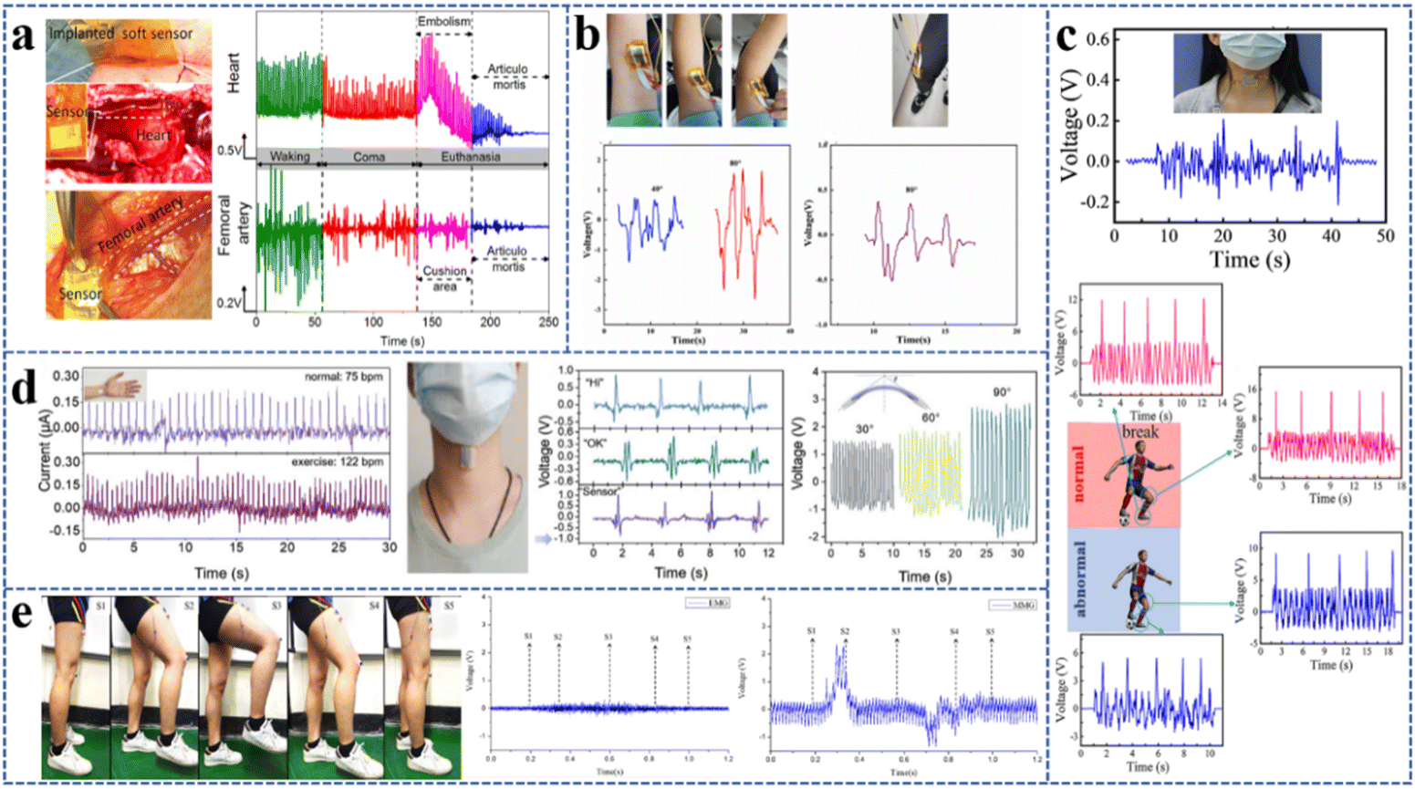 | ||
| Fig. 7 Application of electrospun PVDF-based nanofiber films in medical and health fields: (a) PVDF/HHE sensor for real-time micropressure monitoring of cardiovascular walls. Reproduced from ref. 110 with permission from the American Chemical Society, copyright 2019. (b) Wearable sensor prepared from the PVDF/BiCl3/ZnO nanofiber film used for the detection of the bending and stretching of the left arm and left leg. Reproduced from ref. 102 with permission from Elsevier Ltd, copyright 2021. (c) PVDF-HFP/ZnO composite nanofiber-based highly sensitive piezoelectric sensor for wireless workout monitoring. Reproduced from ref. 122 with permission from the Springer Nature Switzerland AG, copyright 2021. (d) PVDF/PDA@BaTiO3 wearable pressure sensor used to monitor physiological signals. Reproduced from ref. 101 with permission from the Elsevier John Wiley & Sons, Inc., copyright 2021. (e) MMG sensors prepared using electrospun PVDF piezoelectric nanofibers for lower limb rehabilitation exoskeleton. Reproduced from ref. 123 with permission from Elsevier B.V., copyright 2019. | ||
Bioactive piezoelectric materials with charged surfaces can produce electrical charges under mechanical strain. When they are implanted in animals, the electrical stimulation signal will encourage cell division, proliferation, and regeneration processes, which can speed up the healing process of wounds. Electrospun PVDF/PU scaffolds have been demonstrated to be effective for wound healing. Animal movement caused mechanical deformation in the scaffold and generated piezoelectric stimulation, which could enhance cell migration and promote the activity of fibroblasts leading to wound healing.121
The sensors made of electrospun PVDF fiber films can also be used for in vitro monitoring of various physiological activities of the human body. PVDF/BiCl3/ZnO sensors were placed on elbows and knees to monitor human motion. The elbow bending from 0° to 40° and from 0° to 80° resulted in peak output voltage signals of 1.2 V and 3 V, respectively, and the knee bending from 0° to 80° also produced a peak output voltage of 0.6 V (Fig. 7b).102 Piezoelectric sensors made of PVDF-HFP/ZnO composite nanofibers had a high sensitivity of 1.9 V kPa−1. When subjected to a force ranging from 0.02 to 0.5 N, a quick response time of 20 ms was achieved. It could last up to 5000 times of cycle test, indicating high stability and durability. This high-sensitivity sensor was used to track the movement of athletes in real time to minimize the risk of damage. The results showed that the output signal values in the physically exhausted condition were noticeably lower than those in the normal state (Fig. 7c).122
Wearable pressure sensors made of electrospun PVDF/PDA@BaTiO3 nanofibers had an excellent endurance (less than 3% drop after 7400 cycles) and a great sensitivity (3.95 V N−1).101 The sensors could detect the bending and stretching of the finger with the output voltage from ∼1.5 V to ∼3 V with the increase of bending angle from 30° to 90°. It was also observed that the vibration of the throat caused the sensor to produce different signal profiles when the sensor was held to the throat and different phrases were spoken (Fig. 7d). Other researchers used electrospun PVDF fibers to prepare a mechanomyography (MMG) sensor that might be as a motion switch trigger sensor for a lower limb rehabilitation exoskeleton (LLRE). Comparing this trigger sensor with a commercial electromyography (EMG) sensor, it was found that the maximum signal amplitude of the commercial EMG sensor was about 0.2 V, while that of the MMG sensor was about 2.8 V (Fig. 7e).123
4.2 Environmental monitoring
A flexible PVDF sensor was found to produce various piezoelectric signals in response to varying sound, wind, or humidity in the daily environment, and could be used to monitor the environmental conditions.124 The vibration generated by sound or wind is very weak, so the sensitivity of the corresponding sensor is required to be high. The humidity sensor is mainly influenced by the characteristics of additives in the PVDF polymer matrix, thus the performance of additives plays a key role in determining the quality of the device.To track the faint vibration of a loudspeaker, a flexible PVDF/BaTiO3 pressure sensor with a sensitivity of 18.0 V N−1 was developed.60 By attaching the sensor to a stereo, the maximum periodic output voltages of 150 mV and 500 mV could be obtained when the music was played at different sound pressure levels of 60 dB and 80 dB. It was even feasible to discern between different genres of popular music (Fig. 8a). Besides, some researchers prepared a PVDF/graphene/Ce3+ nanofiber pressure sensor, which had outstanding piezoelectric capabilities with an output voltage of 11 V and a maximum power of 6.8 μW at the pressure of 6.6 kPa and achieved an ultra-high pressure measurement sensitivity even at 2 Pa. It could generate different voltage signals under different wind speeds for environmental wind monitoring, and could also identify the same song played by different types of musical instruments (flutes, guitars, and violins) (Fig. 8b).125 A multifunctional sensor was also developed by doping zinc sulfide (ZnS) NRs into PVDF. It was found that the resonance frequency was 86 ± 3 Hz, and the acoustic sensitivity was around 3 V Pa−1. It was suitable for noise detection and could distinguish between acoustic waves in the low-frequency and mid-frequency ranges. In addition, the device could also be used for wind speed monitoring. When the wind speed increased from 15 m s−1 to 25 m s−1, the measured output voltage increased from 1.0 to 4.2 V.126 Some other researchers also built a PVDF piezoelectric film sensor for monitoring wind speed.127 The findings demonstrated that the output voltage increased with the increase of wind speed at various frequencies. Also, the error between the wind speed measured by the PVDF sensor and that measured by the standard anemometer was less than 5%, demonstrating the accuracy of the PVDF sensor for wind speed monitoring (Fig. 8c).
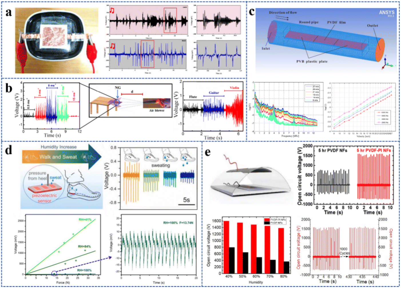 | ||
| Fig. 8 Application of electrospun PVDF-based nanofiber films in the environmental monitoring field: (a) flexible PVDF/BaTiO3 pressure sensor used to monitor the weak vibration of the speaker. Reproduced from ref. 60 with permission from the American Chemical Society, copyright 2020. (b) PVDF/graphene composite nanofibers for fabrication of nanopressure sensors and ultrasensitive acoustic nanogenerators. Reproduced from ref. 125 with permission from the American Chemical Society, copyright 2016. (c) A flow velocity measurement method based on a PVDF piezoelectric sensor. Reproduced from ref. 127 with permission from the MDPI, copyright 2019. (d) PVDF-TrFE/MXene sensor used to monitor ambient humidity. Reproduced from ref. 77 with permission from Elsevier Ltd, copyright 2020. (e) The device prepared by PVDF/PI nanofiber film used for humidity sensing. Reproduced from ref. 128 with permission from Elsevier Ltd, copyright 2020. | ||
Due to the hydrophilic properties of MXene, electrospun PVDF-TrFE/MXene sensors can be utilized as humidity-responsive pressure sensors to measure environmental humidity.77 At varied humidity levels (41%, 84%, and 100%), the voltage signal produced by the enclosed piezoelectric device remained fairly linear to the pressure. In the actual test, the sensor was placed at the heel inside the shoe, and the effect of foot sweating on the output voltage was tested with the increase of jogging time. Results showed that the longer the jogging time, the more serious the foot sweating, and the lower the output voltage (Fig. 8d). Devices made of PVDF/PI nanofiber films have also demonstrated humidity sensing application capabilities. Compared to the pure PVDF device with an open-circuit voltage of about 800 V, the PVDF/PI device could generate a higher value of 1600 V. When the relative humidity fluctuated between 40% and 80%, the output voltage of the PVDF/PI device decreased with the increasing humidity, allowing it to be employed as humidity sensors (Fig. 8e). The output voltage of the PVDF/PI device was also evaluated for 1000 cycles without a significant decrease at a relative humidity of 45%.128
4.3 Energy harvesting
The market for smart wearables has recently taken off, and experts have been paying close attention to the energy demand of these products. In order to overcome the power supply issue for the majority of smart wearable technology, flexible and sustainable energy harvesting devices should be developed. In 2006, Wang's group48 made the first realization of the conversion of mechanical energy to electrical energy in the nanoscale, which was the fundamental principle to prepare TENGs and PENGs for energy harvesting and powering small devices.75,129 High-performance nanogenerators could also be integrated with sensor devices to create self-powered sensor devices.130A flexible PENG that can power small portable and wearable electronics, such as watches and cell phones, has been prepared. It is expected to alleviate the need for miniaturized energy sources.99 The power generation layer of this nanogenerator was made of PVDF and silane-modified KNN (SM-KNN) by electrospinning, and it was found that the PVDF/SM-KNN nanofiber film had good piezoelectric properties because the modified KNN reduced the coalescence of nanofillers and further induced the interaction between PVDF chains and KNN NRs to improve the crystallinity of the composite fiber. A high output voltage of ∼21 V, an output current of ∼22 mA, a current density of ∼5.5 mA cm−2, and a power density of ∼15.5 mW cm−2 were produced by the PVDF/3% SM-KNN nanofiber film, which could be used to light an LED (Fig. 9a). A very flexible electrospun PVDF/PANI/g-C3N4 blended nanocomposite fiber (PPBF) nanogenerator for piezoelectric energy harvesting was also reported.131 The resultant PPBF nanogenerator had maximum output values of ∼30 V, 3.7 μA, 14.7 μW cm−2, and ∼20% for output voltage, output current, power density per unit area, and conversion efficiency. The results also demonstrated its excellent endurance and stability after more than 50000 stress and de-stress cycles (Fig. 9b).
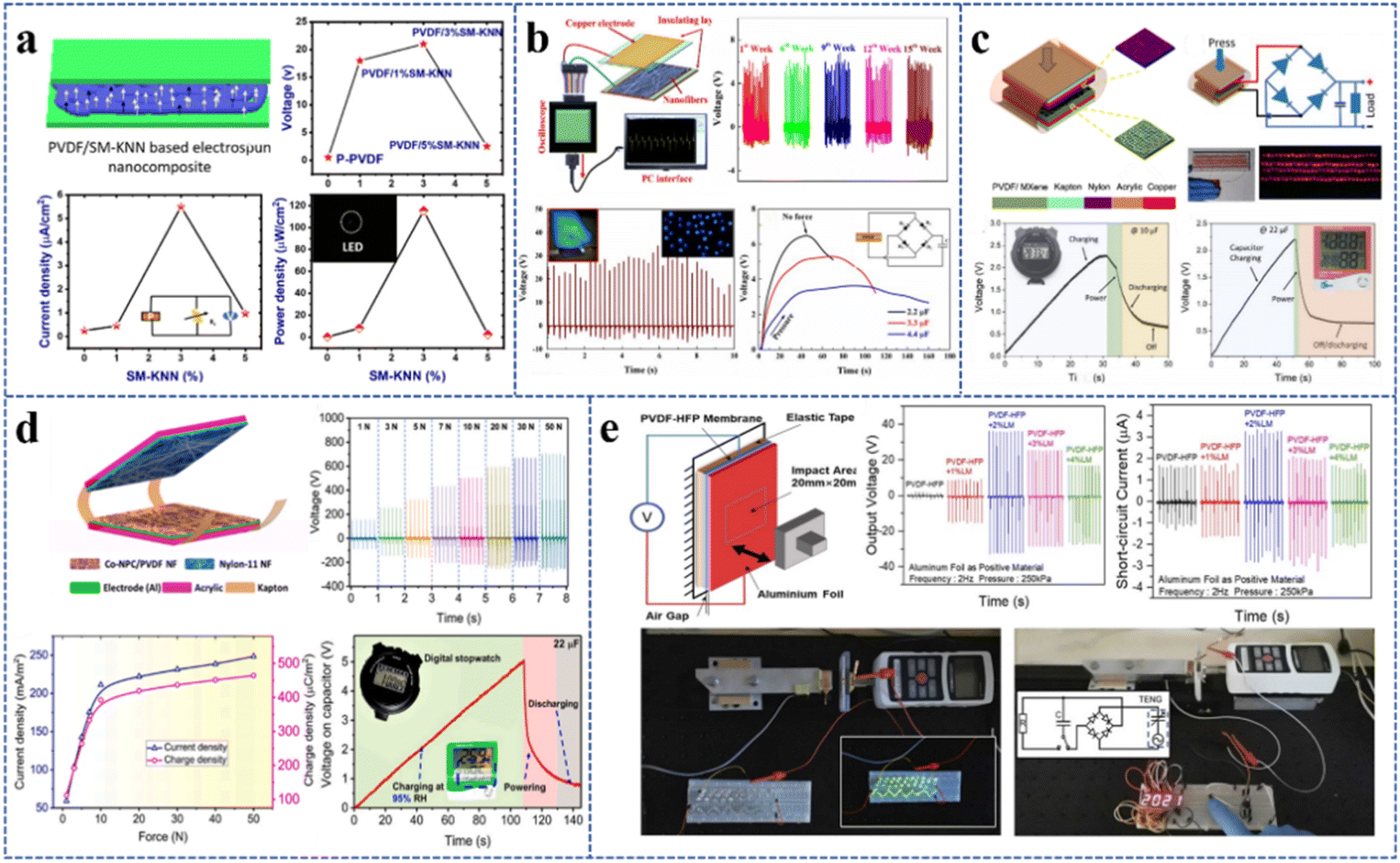 | ||
| Fig. 9 Application of electrospun PVDF-based nanofiber films in the energy harvesting field: (a) PENG prepared from the PVDF/SM-KNN nanocomposite piezoelectric material. Reproduced from ref. 99 with permission from Elsevier Ltd, copyright 2020. (b) PVDF nanofibers with embedded PANI-graphitic carbon nitride nanosheet composites for piezoelectric energy conversion. Reproduced from ref. 131 with permission from the American Chemical Society, copyright 2019. (c) High-performance TENG based on MXene functionalized PVDF composite nanofibers. Reproduced from ref. 132 with permission from Elsevier Ltd, copyright 2020. (d) PVDF/Co-NPC nanofiber films for a high-performance TENG. Reproduced from ref. 133 with permission from Elsevier Ltd, copyright 2022. (e) Electrospun PVDF-HFP/LM nanofiber film with exceptional triboelectric performance. Reproduced from ref. 134 with permission from Elsevier Ltd, copyright 2021. | ||
Compared to PENGs, TENGs have a better piezoelectric output and power efficiency due to their special structure. The TENG made by using electrospun PVDF/MXene and nylon 6/6 nanofiber films as the efficient negative frictional electric layer could deliver a peak power of 4.6 mW (power density of 11.213 W m−2) at a matched impedance of 2 MΩ,132 and also demonstrated outstanding stability at 60000 contact separation cycles. More than 120 commercial red LEDs, a sports watch, or a thermohygrograph could be powered by the energy produced by the TENG (Fig. 9c). Besides, the cobalt-based nanoporous carbon (Co-NPC) combined with PVDF was also used as a highly electronegative friction material for improving the performance of TENGs in mechanical energy harvesting. At the Co-NPC content of 0.5 wt%, the maximum peak voltage of the PVDF/Co-NPC nanofiber film was 710 V, which was 2.1 times higher than that of pure PVDF.133 A high-performance PVDF/Co-NPC-TENG in contact separation mode was created using the developed PVDF/Co-NPC nanofiber film in combination with the nylon-11 nanofiber film. The highest voltage, current density, and charge density of 948 V, 248.66 mA m−2, and 464 μC m−2 were obtained at a pressure of 50 N (Fig. 9d). Ambient humidity had a significant impact on the output performance of the TENG, and it was found that increasing the relative humidity would reduce the output voltage of the TENG. However, the PVDF/Co-NPC-TENG exhibited good charging capabilities for storage capacitors and could operate low-power electronics, such as digital stopwatches, at a high relative humidity level of 95%. To improve the triboelectric properties of the fiber film, liquid metal (LM) Galinstan nanodroplets were also added to prepare electrospun PVDF-HFP/LM nanofibers.134 The TENG made of them was anticipated to provide power for smart devices as a sustainable energy source. PVDF-HFP added with 2 wt% LM was tested to have the highest peak voltage, current, and power density. At a shock frequency of 5 Hz and a shock pressure of 250 kPa, the measured voltage across the external resistor tended to stabilize at around 1680 V with a resistance of more than 500 MΩ. The electrical energy generated by the TENG could simultaneously light 80 LEDs and could also be successfully converted to DC and stored in a 22 μF capacitor using a bridge rectifier circuit to illuminate a seven-segment LED display showing “2021” (Fig. 9e).
5. Summary and prospects
Electrospinning is a straightforward and economical method for the fabrication of polymeric nanofibers. Many researchers have been interested in electrospinning since it has given them a new option to create high-efficiency PVDF piezoelectric films. The strategies to improve the piezoelectric output performance of electrospun PVDF-based fiber films are primarily focusing on filler doping and structural design. The relationship between the doping filler content and the output voltage of PVDF-based composite fiber films has been reported in numerous publications. Lead-free piezoelectric ceramic materials, conductive materials, and some other inorganic and organic materials have relatively good effects on the output voltage of PVDF-based fiber films and are frequently used as doped fillers. Effective structural design, including a highly oriented structure, core–shell structure, and multilayer composite structure, can also improve the piezoelectric performance of PVDF-based fiber films to a certain extent. The mechanical properties have a significant impact on the performance and stability of the devices. It is possible to achieve higher mechanical strength by combining PVDF with polymers with better mechanical properties to prepare composite fibers, adding nanomaterials in the PVDF matrix for reinforcement, appropriately increasing the thickness of fiber films, and preparing fiber films with composite structures. The performance of the ultimate PVDF-based piezoelectric devices is expected to be further enhanced by the exploration of more efficient additives, structures, and combinations between them in the future. In-depth investigations of the synergistic design of materials and structures as well as the mix of various materials are essential. Although the preparation of electrospun PVDF-based piezoelectric fiber films and their applications are booming, there is currently no unified test standard for researchers to use when evaluating piezoelectric output, so that the comparability between various research endeavors is insufficient.Electrospun PVDF-based fiber films can be used to prepare sensors, nanogenerators, and other piezoelectric devices, and they have been applied in a variety of fields because of their flexibility, lightweight, and biocompatible characteristics. Piezoelectric sensors have been applied in implantable sensing, human rehabilitation, motion monitoring, speech recognition, wind speed monitoring, and other aspects. Nanogenerators have been used for energy harvesting to provide sustainable energy for smart homes or smart wearable devices. The sensors and nanogenerators based on electrospun PVDF fibers exhibit excellent performance and have great commercial value in the future. Although improved research outcomes have been achieved, the load-matching standard and minimum stability requirements of devices in practical applications need to be clarified, and more complete equipment integration is needed.
Author contributions
Mengdi Zhang, Chengkun Liu, Boyu Li, Yutong Shen, and Hao Wang discussed the contents as well as wrote and reviewed the manuscript. Fenglei Zhou, Keyu Ji, Liang Wei, Xue Mao, and Runjun Sun edited, reviewed, and revised the manuscript. All authors have read and agreed to the published version of the manuscript.Conflicts of interest
There are no conflicts to declare.Acknowledgements
The authors gratefully acknowledge the financial support from the National Natural Science Foundation of China (51503168) and the Innovation Capability Support Plan of Shaanxi, China (2020PT-043).Notes and references
- Z. A. Alhasssan, Y. S. Burezq, R. Nair and N. Shehata, J. Nanomater., 2018, 2018, 12 CrossRef.
- C. K. Jeong, J. H. Han, H. Palneedi, H. Park, G. T. Hwang, B. Joung, S. G. Kim, H. J. Shin, I. S. Kang, J. Ryu and K. J. Lee, APL Mater., 2017, 5, 074102 CrossRef.
- X. Chen, M. Han, H. Chen, X. Cheng, Y. Song, Z. Su, Y. Jiang and H. Zhang, Nanoscale, 2017, 9, 1263 RSC.
- J. Huang, Y. Hao, M. Zhao, W. Li, F. Huang and Q. Wei, ACS Appl. Mater. Interfaces, 2021, 13, 24774 CrossRef CAS PubMed.
- S. M. S. Rana, M. T. Rahman, M. Salauddin, S. Sharma, P. Maharjan, T. Bhatta, H. Cho, C. Park and J. Y. Park, ACS Appl. Mater. Interfaces, 2021, 13, 4955 CrossRef CAS PubMed.
- T. Li, M. Qu, C. Carlos, L. Gu, F. Jin, T. Yuan, X. Wu, J. Xiao, T. Wang, W. Dong, X. Wang and Z. Q. Feng, Adv. Mater., 2021, 33, 2006093 CrossRef CAS PubMed.
- Q. Zhou, T. Chen, S. Cao, X. Xia, Y. Bi and X. Xiao, Appl. Phys. A, 2021, 127, 667 CrossRef CAS.
- N. Shehata, A. H. Hassanin, E. Elnabawy, R. Nair, S. A. Bhat and I. Kandas, Sensors, 2020, 20, 3111 CrossRef CAS PubMed.
- C. Chang, V. H. Tran, J. Wang, Y. K. Fuh and L. Lin, Nano Lett., 2010, 10, 726 CrossRef CAS PubMed.
- A. J. Lovinger, Science, 1983, 220, 1115 CrossRef CAS PubMed.
- X. Ma, J. Liu, C. Ni, D. C. Martin, D. B. Chase and J. F. Rabolt, ACS Macro Lett., 2012, 1, 428 CrossRef CAS PubMed.
- P. Martins, A. C. Lopes and S. Lanceros-Mendez, Prog. Polym. Sci., 2014, 39, 683 CrossRef CAS.
- J. Fang, H. Niu, H. Wang, X. Wang and T. Lin, Energy Environ. Sci., 2013, 6, 2196 RSC.
- L. Xie, G. Wang, C. Jiang, F. Yu and X. Zhao, Crystals, 2021, 11, 644 CrossRef CAS.
- Y. Huang, G. Rui, Q. Li, E. Allahyarov, R. Li, M. Fukuto, G. J. Zhang, J. Z. Xu, Z. M. Li, P. L. Taylor and L. Zhu, Nat. Commun., 2021, 12, 675 CrossRef CAS PubMed.
- V. Sencadas, R. Gregorio and S. Lanceros-Méndez, J. Macromol. Sci. B, 2009, 48, 514 CrossRef CAS.
- H. Pan, B. Na, R. Lv, C. Li, J. Zhu and Z. Yu, J. Polym. Sci., Part B: Polym. Phys., 2012, 50, 1433 CrossRef CAS.
- Z. H. Liu, C. T. Pan, L. W. Lin, J. C. Huang and Z. Y. Ou, Smart Mater. Struct., 2014, 23, 025003 CrossRef CAS.
- A. Lund, C. Gustafsson, H. Bertilsson and R. W. Rychwalski, Compos. Sci. Technol., 2011, 71, 222 CrossRef CAS.
- C. M. Wu, M. H. Chou and W. Y. Zeng, Nanomaterials, 2018, 8, 420 CrossRef PubMed.
- L. Persano, C. Dagdeviren, Y. Su, Y. Zhang, S. Girardo, D. Pisignano, Y. Huang and J. A. Rogers, Nat. Commun., 2013, 4, 1633 CrossRef PubMed.
- W. Wang, J. Yang and Z. Liu, IEEE Trans. Dielectr. Electr. Insul., 2017, 24, 697 CAS.
- Z. Yin, B. Tian, Q. Zhu and C. Duan, Polymers, 2019, 11, 2033 CrossRef CAS PubMed.
- W. Yan, G. Noel, G. Loke, E. Meiklejohn, T. Khudiyev, J. Marion, G. Rui, J. Lin, J. Cherston, A. Sahasrabudhe, J. Wilbert, I. Wicaksono, R. W. Hoyt, A. Missakian, L. Zhu, C. Ma, J. Joannopoulos and Y. Fink, Nature, 2022, 603, 616 CrossRef CAS PubMed.
- M. Du, L. Huang, J. Zheng, Y. Xi, Y. Dai, W. Zhang, W. Yan, G. Tao, J. Qiu, K. So, C. Ren and S. Zhou, Adv. Sci., 2020, 7, 2001410 CrossRef CAS PubMed.
- S. Qian, M. Liu, Y. Dou, Y. Fink and W. Yan, Natl. Sci. Rev., 2022, 10, 202 CrossRef PubMed.
- S. Egusa, Z. Wang, N. Chocat, Z. M. Ruff, A. M. Stolyarov, D. Shemuly, F. Sorin, P. T. Rakich, J. D. Joannopoulos and Y. Fink, Nat. Mater., 2010, 9, 643 CrossRef CAS PubMed.
- S. Agarwal, A. Greiner and J. H. Wendorff, Adv. Funct. Mater., 2009, 19, 2863 CrossRef CAS.
- L. Zhang, J. Gui, Z. Wu, R. Li, Y. Wang, Z. Gong, X. Zhao, C. Sun and S. Guo, Nano Energy, 2019, 65, 103924 CrossRef CAS.
- Z. Zhao, J. Li, X. Yuan, X. Li, Y. Zhang and J. Sheng, J. Appl. Polym. Sci., 2005, 97, 466 CrossRef CAS.
- T. Lei, L. Yu, L. Wang, F. Yang and D. Sun, J. Macromol. Sci. B, 2014, 54, 91 CrossRef.
- B. Zaarour, L. Zhu and X. Jin, Soft Mater., 2019, 17, 181 CrossRef CAS.
- S. Gee, B. Johnson and A. L. Smith, J. Membr. Sci., 2018, 563, 804 CrossRef CAS.
- H. Jiyong, G. Yuanyuan, Z. Hele, Z. Yinda and Y. Xudong, J. Text. Inst., 2017, 109, 843 CrossRef.
- F. Huang, Q. Wei, J. Wang, Y. Cai and Y. Huang, e-Polymers, 2008, 8, 1758 Search PubMed.
- N. Jia, Q. Xing, G. Xia, J. Sun, R. Song and W. Hang, Mater. Lett., 2015, 139, 212 CrossRef CAS.
- Y. Ahn, J. Y. Lim, S. M. Hong, J. Lee, J. Ha, H. J. Choi and Y. Seo, J. Phys. Chem. C, 2013, 117, 11791 CrossRef CAS.
- N. Chamankar, R. Khajavi, A. A. Yousefi, A. Rashidi and F. Golestanifard, Ceram. Int., 2020, 46, 19669 CrossRef CAS.
- J. E. Lee, Y. E. Shin, G. H. Lee, J. Kim, H. Ko and H. G. Chae, Composites, Part B, 2021, 223, 109098 CrossRef CAS.
- S. Sharafkhani and M. Kokabi, AIP Conf. Proc., 2018, 1920, 020001 CrossRef.
- R. T. Selvan, C. Y. Jia, W. A. D. M. Jayathilaka, A. Chinappan, H. Alam and S. Ramakrishna, Nano, 2020, 15, 2050049 CrossRef CAS.
- S. Lv, Y. Han, L. Shuai, B. Chen and J. Wan, J. Lumin., 2021, 239, 118303 CrossRef CAS.
- H. Lee, H. Kim, D. Y. Kim and Y. Seo, ACS Omega, 2019, 4, 2610 CrossRef CAS PubMed.
- K. I. Park, M. Lee, Y. Liu, S. Moon, G. T. Hwang, G. Zhu, J. E. Kim, S. O. Kim, D. K. Kim, Z. L. Wang and K. J. Lee, Adv. Mater., 2012, 24, 2999 CrossRef CAS PubMed.
- Z. H. Lin, Y. Yang, J. M. Wu, Y. Liu, F. Zhang and Z. L. Wang, J. Phys. Chem. Lett., 2012, 3, 3599 CrossRef CAS PubMed.
- J. H. Jung, M. Lee, J. I. Hong, Y. Ding, C. Y. Chen, L. J. Chou and Z. L. Wang, Acs Nano, 2011, 5, 10041 CrossRef CAS PubMed.
- J. H. Jung, C. Y. Chen, B. K. Yun, N. Lee, Y. Zhou, W. Jo, L. J. Chou and Z. L. Wang, Nanotechnology, 2012, 23, 375401 CrossRef PubMed.
- Z. L. Wang and J. H. Song, Science, 2006, 312, 242 CrossRef CAS PubMed.
- F. R. Fan, W. Tang and Z. L. Wang, Adv. Mater., 2016, 28, 4283 CrossRef CAS PubMed.
- L. Csoka, I. C. Hoeger, O. J. Rojas, I. Peszlen, J. J. Pawlak and P. N. Peralta, ACS Macro Lett., 2012, 1, 867 CrossRef CAS PubMed.
- W. Wang, Y. Zheng, X. Jin, Y. Sun, B. Lu, H. Wang, J. Fang, H. Shao and T. Lin, Nano Energy, 2019, 56, 588 CrossRef CAS.
- L. Yuan, W. Fan, X. Yang, S. Ge, C. Xia, S. Y. Foong, R. K. Liew, S. Wang, Q. V. Le and S. S. Lam, Compos. Commun., 2021, 25, 100680 CrossRef.
- S. Anwar, M. H. Amiri, S. Jiang, M. M. Abolhasani, P. R. F. Rocha and K. Asadi, Adv. Funct. Mater., 2020, 31, 2004326 CrossRef.
- V. Sencadas, C. Garvey, S. Mudie, J. J. K. Kirkensgaard, G. Gouadec and S. Hauser, Nano Energy, 2019, 66, 104106 CrossRef CAS.
- J. Jiang, S. Tu, R. Fu, J. Li, F. Hu, B. Yan, Y. Gu and S. Chen, ACS Appl. Mater. Interfaces, 2020, 12, 33989 CrossRef CAS PubMed.
- D. Wang, P. Shi, X. Li, P. Zhou, K. Zhao, Y. Wei, C. Jiang, J. Liang and R. A. Dorey, Ceram. Int., 2018, 44, 14258 CrossRef CAS.
- M. Koç, L. Paralı and O. Şan, Polym. Test., 2020, 90, 106695 CrossRef.
- Y. Qi and M. C. McAlpine, Energy Environ. Sci., 2010, 3, 1275 RSC.
- I. Choi, S. J. Lee, J. C. Kim, Y. Kim, D. Y. Hyeon, K. S. Hong, J. Suh, D. Shina, H. Y. Jeong and K. I. Park, Appl. Surf. Sci., 2020, 511, 145614 CrossRef CAS.
- M. Kumar, N. D. Kulkarni and P. Kumari, Mater. Today: Proc., 2022, 56, 1151 CAS.
- S. Bairagi and S. W. Ali, Energy Technol., 2019, 7, 1900538 CrossRef CAS.
- N. Sinha, S. Goel, A. J. Joseph, H. Yadav, K. Batra, M. K. Gupta and B. Kumar, Ceram. Int., 2018, 44, 8582 CrossRef CAS.
- T. G. Smijs and S. Pavel, Nanotechnol., Sci. Appl., 2011, 4, 95 CrossRef CAS PubMed.
- N. A. Monteiro-Riviere, K. Wiench, R. Landsiedel, S. Schulte, A. O. Inman and J. E. Riviere, Toxicol. Sci., 2011, 123, 264 CrossRef CAS PubMed.
- K. Schilling, B. Bradford, D. Castelli, E. Dufour, J. F. Nash, W. Pape, S. Schulte, I. Tooley, J. Boschi and F. Schellauf, Photochem. Photobiol. Sci., 2010, 9, 495 CrossRef CAS PubMed.
- G. Y. Li, H. D. Zhang, K. Guo, X. S. Ma and Y. Z. Long, Mater. Res. Express, 2020, 7, 095502 CrossRef CAS.
- X. Pu, J. W. Zha, C. L. Zhao, S. B. Gong, J. F. Gao and R. K. Y. Li, Chem. Eng. J., 2020, 398, 125526 CrossRef CAS.
- J. Li, S. Chen, W. Liu, R. Fu, S. Tu, Y. Zhao, L. Dong, B. Yan and Y. Gu, J. Phys. Chem. C, 2019, 123, 11378 CrossRef CAS.
- Z. Liu, G. Li, Q. Qin, L. Mi, G. Li, G. Zheng, C. Liu, Q. Li and X. Liu, Adv. Compos. Hybrid Mater., 2021, 4, 1215 CrossRef CAS.
- R. Fu, S. Chen, Y. Lin, S. Zhang, J. Jiang, Q. Li and Y. Gu, Mater. Lett., 2017, 187, 86 CrossRef CAS.
- L. Huang, C. Lu, F. Wang and L. Wang, RSC Adv., 2014, 4, 45220 RSC.
- A. Samadi, S. M. Hosseini and M. Mohseni, Org. Electron., 2018, 59, 149 CrossRef CAS.
- H. Yu, T. Huang, M. Lu, M. Mao, Q. Zhang and H. Wang, Nanotechnology, 2013, 24, 405401 CrossRef PubMed.
- O. M. Zeyrek, S. Oguzlar, E. C. Doluel, U. Kartal and M. Yurddaskal, J. Mater. Sci.: Mater. Electron., 2019, 31, 1960 CrossRef.
- J. Yang, Y. Zhang, Y. Li, Z. Wang, W. Wang, Q. An and W. Tong, Mater. Today Commun., 2021, 26, 101629 CrossRef CAS.
- Q. Zhao, L. Yang, Y. Ma, H. Huang, H. He, H. Ji, Z. Wang and J. Qiu, J. Alloys Compd., 2021, 886, 161069 CrossRef CAS.
- S. Wang, H. Q. Shao, Y. Liu, C. Y. Tang, X. Zhao, K. Ke, R. Y. Bao, M. B. Yang and W. Yang, Compos. Sci. Technol., 2021, 202, 108600 CrossRef CAS.
- F. Mokhtari, M. Shamshirsaz, M. Latifi and J. Foroughi, Polymers, 2020, 12, 2697 CrossRef CAS PubMed.
- F. Mokhtari, M. Latifi, M. Shamshirsaz, M. Khelghatdoost and S. Rahmani, J. Text. Inst., 2017, 108, 1917 CrossRef CAS.
- C. K. Yen, K. Dutt, Y. S. Yao, W. J. Wu, Y. L. Shiue, C. T. Pan, C. W. Chen and W. F. Chen, Polymers, 2022, 14, 331 CrossRef CAS PubMed.
- C. Li, H. Wang, X. Yan, H. Chen, Y. Fu and Q. Meng, Coatings, 2021, 11, 1495 CrossRef CAS.
- C. Chen, Z. Bai, Y. Cao, M. Dong, K. Jiang, Y. Zhou, Y. Tao, S. Gu, J. Xu, X. Yin and W. Xu, Compos. Sci. Technol., 2020, 192, 108100 CrossRef CAS.
- F. Mokhtari, M. Shamshirsaz and M. Latifi, Polym. Eng. Sci., 2016, 56, 61 CrossRef CAS.
- J. Yang, J. Wang, Q. Zhang, F. Chen, H. Deng, K. Wang and Q. Fu, Polymer, 2011, 52, 4970 CrossRef CAS.
- R. Neppalli, S. Wanjale, M. Birajdar and V. Causin, Eur. Polym. J., 2013, 49, 90 CrossRef CAS.
- Y. Xin, X. Qi, H. Tian, C. Guo, X. Li, J. Lin and C. Wang, Mater. Lett., 2016, 164, 136 CrossRef CAS.
- S. Shetty, A. Mahendran and S. Anandhan, Soft Matter, 2020, 16, 5679 RSC.
- S. Zhang and Q. An, Chem. J. Chin. Univ., 2021, 42, 1114 Search PubMed.
- B. Adeli, A. A. Gharehaghaji and A. A. A. Jeddi, Iran. Polym. J., 2021, 30, 535 CrossRef.
- C. Merlini, A. Pegoretti, T. M. Araujo, S. D. A. S. Ramoaa, W. H. Schreiner and G. M. O. Barra, Synth. Met., 2016, 213, 34 CrossRef CAS.
- X. Cai, Z. Zheng, J. Xu, X. Tang and T. Lei, J. Macromol. Sci. B, 2016, 56, 75 CrossRef.
- A. Sengupta, S. Das, S. Dasgupta, P. Sengupta and P. Datta, ACS Biomater. Sci. Eng., 2021, 7, 1673 CrossRef CAS PubMed.
- R. S. Sabry and A. D. Hussein, Polym. Test., 2019, 79, 106001 CrossRef CAS.
- S. Bairagi and S. W. Ali, Int. J. Energy Res., 2020, 44, 5545 CrossRef CAS.
- D. Ponnamma, H. Parangusan, A. Tanvir and M. A. A. AlMa′adeed, Mater. Des., 2019, 184, 108176 CrossRef CAS.
- S. Bairagi and S. W. Ali, Soft Matter, 2020, 16, 4876 RSC.
- M. Hasanzadeh, M. R. Ghahhari and S. M. Bidoki, J. Mater. Sci.: Mater. Electron., 2021, 32, 15789 CrossRef CAS.
- K. Shi, B. Sun, X. Huang and P. Jiang, Nano Energy, 2018, 52, 153 CrossRef CAS.
- S. Bairagi and S. W. Ali, Energy, 2020, 198, 117385 CrossRef CAS.
- S. Banerjee, S. Bairagi and S. W. Ali, Energy, 2022, 244, 123102 CrossRef CAS.
- Y. Su, C. Chen, H. Pan, Y. Yang, G. Chen, X. Zhao, W. Li, Q. Gong, G. Xie, Y. Zhou, S. Zhang, H. Tai, Y. Jiang and J. Chen, Adv. Funct. Mater., 2021, 31, 2010962 CrossRef CAS.
- D. Zhang, X. Zhang, X. Li, H. Wang, X. Sang, G. Zhu and Y. Yeung, Eur. Polym. J., 2022, 166, 110956 CrossRef CAS.
- T. Sharma, S. Naik, J. Langevine, B. Gill and J. X. J. Zhang, IEEE Trans. Biomed. Eng., 2015, 62, 188 Search PubMed.
- Y. M. Yousry, K. Yao, A. M. Mohamed, W. H. Liew, S. Chen and S. Ramakrishna, Adv. Funct. Mater., 2020, 30, 1910592 CrossRef CAS.
- Y. Jiang, L. Gong, X. Hu, Y. Zhao, H. Chen, L. Feng and D. Zhang, Polymers, 2018, 10, 364 CrossRef PubMed.
- N. Shehata, E. Elnabawy, M. Abdelkader, A. H. Hassanin, M. Salah, R. Nair and S. A. Bhat, Polymers, 2018, 10, 965 CrossRef PubMed.
- M. Zhu, M. Lou, I. Abdalla, J. Yu, Z. Li and B. Ding, Nano Energy, 2020, 69, 104429 CrossRef CAS.
- D. Ponnamma D, M. M. Chamakh, A. M. Alahzm, N. Salim, N. Hameed and M. A. A. AlMaadeed, Polymers, 2020, 12, 2344 CrossRef PubMed.
- S. Wang, K. Shi, B. Chai, S. Qiao, Z. Huang, P. Jiang and X. Huang, Nano Mater. Sci., 2021, 4, 126 CrossRef.
- T. Li, Z. Q. Feng, M. Qu, K. Yan, T. Yuan, B. Gao, T. Wang, W. Dong and J. Zheng, ACS Nano, 2019, 13, 10062 CrossRef CAS PubMed.
- K. Maity and D. Mandal, ACS Appl. Mater. Interfaces, 2018, 10, 18257 CrossRef CAS PubMed.
- Y. Li, M. Xu, Y. Xia, J. Wu, X. Sun, S. Wang, G. Hu and C. Xiong, Chem. Eng. J., 2020, 388, 124205 CrossRef CAS.
- S. Kalani, R. Kohandani and R. Bagherzadeh, RSC Adv., 2020, 10, 35090 RSC.
- M. Kato and K. I. Kakimoto, Mater. Lett., 2015, 156, 183 CrossRef CAS.
- X. Wang, F. Sun, G. Yin, Y. Wang, B. Liu and M. Dong, Sensors, 2018, 18, 330 CrossRef PubMed.
- D. Chen, C. Wang, W. Chen, Y. Chen and J. X. J. Zhang, Biosens. Bioelectron., 2015, 74, 1047 CrossRef CAS PubMed.
- T. Li, Z. Q. Feng, K. Yan, T. Yuan, W. Wei, X. Yuan, C. Wang, T. Wang, W. Dong and J. Zheng, J. Mater. Chem. B, 2018, 6, 5343 RSC.
- R. F. Valentini, T. G. Vargo, J. A. G. Gardella Jr and P. Aebischer, Biomaterials, 1992, 13, 183 CrossRef CAS PubMed.
- A. Bouaziz, A. Richert and A. Caprani, Biomaterials, 1997, 18, 107 CrossRef CAS PubMed.
- Z. Yang, Z. Wu, D. Jiang, R. Wei, X. Mai, D. Pan, S. Vupputuri, L. Weng, N. Naik and Z. Guo, J. Mater. Chem. C, 2021, 9, 2752 RSC.
- H. F. Guo, Z. S. Li, S. W. Dong, W. J. Chen, L. Deng, Y. F. Wang and D. J. Ying, Colloids Surf., B, 2012, 96, 29 CrossRef CAS PubMed.
- G. Y. Li, J. Li, Z. J. Li, Y. P. Zhang, X. Zhang, Z. J. Wang, W. P. Han, B. Sun, Y. Z. Long and H. D. Zhang, Adv. Compos. Hybrid Mater., 2021, 5, 766 CrossRef.
- C. T. Pan, C. C. Chang, Y. S. Yang, C. K. Yen, Y. H. Kao and Y. L. Shiue, Sens. Actuators, A, 2020, 301, 111708 CrossRef CAS.
- J. Zhao, F. Li, Z. Wang, P. Dong, G. Xia and K. Wang, J. Mater. Sci.: Mater. Electron., 2021, 32, 14715 CrossRef CAS.
- S. Garain, S. Jana, T. K. Sinha and D. Mandal, ACS Appl. Mater. Interfaces, 2016, 8, 4532 CrossRef CAS PubMed.
- A. Sultana, M. M. Alam, S. K. Ghosh, T. R. Middya and D. Mandal, Energy, 2019, 166, 963 CrossRef CAS.
- Q. Li, J. Xing, D. Shang and Y. Wang, Sensors, 2019, 19, 1657 CrossRef CAS PubMed.
- M. Tayyab, J. Wang, J. Wang, M. Maksutoglu, H. Yu, G. Sun, F. Yildiz, M. Eginligil and W. Huang, Nano Energy, 2020, 77, 105178 CrossRef CAS.
- H. Y. Mi, X. Jing, Q. Zheng, L. Fang, H. X. Huang, L. S. Turng and S. Gong, Nano Energy, 2018, 48, 327 CrossRef CAS.
- J. Liu, B. Yang, L. Lu, X. Wang, X. Li, X. Chen and J. Liu, Sens. Actuators, A, 2020, 303, 111796 CrossRef CAS.
- M. Khalifa and S. Anandhan, ACS Appl. Nano Mater., 2019, 2, 7328 CrossRef CAS.
- T. Bhatta, P. Maharjan, H. Cho, C. Park, S. H. Yoon, S. Sharma, M. Salauddin, M. T. Rahman, S. M. S. Rana and J. Y. Park, Nano Energy, 2021, 81, 105670 CrossRef CAS.
- M. T. Rahman, S. M. S. Rana, M. A. Zahed, S. Lee, E. S. Yoon and J. Y. Park, Nano Energy, 2022, 94, 106921 CrossRef CAS.
- Z. Sha, C. Boyer, G. Li, Y. Yu, F. M. Allioux, K. K. Zadeh, C. H. Wang and J. Zhang, Nano Energy, 2022, 92, 106713 CrossRef CAS.
| This journal is © The Royal Society of Chemistry 2023 |