
 Open Access Article
 This Open Access Article is licensed under a Creative Commons Attribution-Non Commercial 3.0 Unported Licence
3D organic bioelectronics for electrical monitoring of human adult stem cells†
Achilleas
Savva
 *a,
Janire
Saez
abcd,
Aimee
Withers
a,
Chiara
Barberio
a,
Verena
Stoeger
a,
Shani
Elias-Kirma
a,
Zixuan
Lu
a,
Chrysanthi-Maria
Moysidou
a,
Konstantinos
Kallitsis
a,
Charalampos
Pitsalidis
efa and
Róisín M.
Owens
*a
*a,
Janire
Saez
abcd,
Aimee
Withers
a,
Chiara
Barberio
a,
Verena
Stoeger
a,
Shani
Elias-Kirma
a,
Zixuan
Lu
a,
Chrysanthi-Maria
Moysidou
a,
Konstantinos
Kallitsis
a,
Charalampos
Pitsalidis
efa and
Róisín M.
Owens
*a
aDepartment of Chemical Engineering and Biotechnology, University of Cambridge, CB3 0AS Cambridge, UK. E-mail: as3024@cam.ac.uk; rmo37@cam.ac.uk
bMicrofluidics Cluster UPV/EHU, BIOMICs Microfluidics Group, Lascaray Research Center, University of the Basque Country UPV/EHU, Avenida Miguel de Unamuno, 3, 01006, Vitoria-Gasteiz, Spain
cBasque Foundation for Science, IKERBASQUE, E-48011 Bilbao, Spain
dBioaraba Health Research Institute, Microfluidics Cluster UPV/EHU, Vitoria-Gasteiz, Spain
eDepartment of Physics, Khalifa University of Science and Technology, P. O. Box 127788, Abu Dhabi, United Arab Emirates
fHealthcare Engineering Innovation Center (HEIC), Khalifa University of Science and Technology, Abu Dhabi, United Arab Emirates
First published on 8th June 2023
Abstract
Three-dimensional in vitro stem cell models have enabled a fundamental understanding of cues that direct stem cell fate. While sophisticated 3D tissues can be generated, technology that can accurately monitor these complex models in a high-throughput and non-invasive manner is not well adapted. Here we show the development of 3D bioelectronic devices based on the electroactive polymer poly(3,4-ethylenedioxythiophene)-poly(styrenesulfonate)–(PEDOT:PSS) and their use for non-invasive, electrical monitoring of stem cell growth. We show that the electrical, mechanical and wetting properties as well as the pore size/architecture of 3D PEDOT:PSS scaffolds can be fine-tuned simply by changing the processing crosslinker additive. We present a comprehensive characterization of both 2D PEDOT:PSS thin films of controlled thicknesses, and 3D porous PEDOT:PSS structures made by the freeze-drying technique. By slicing the bulky scaffolds we generate homogeneous, porous 250 μm thick PEDOT:PSS slices, constituting biocompatible 3D constructs able to support stem cell cultures. These multifunctional slices are attached on indium-tin oxide substrates (ITO) with the help of an electrically active adhesion layer, enabling 3D bioelectronic devices with a characteristic and reproducible, frequency dependent impedance response. This response changes drastically when human adipose derived stem cells (hADSCs) grow within the porous PEDOT:PSS network as revealed by fluorescence microscopy. The increase of cell population within the PEDOT:PSS porous network impedes the charge flow at the interface between PEDOT:PSS and ITO, enabling the interface resistance (R1) to be used as a figure of merit to monitor the proliferation of stem cells. The non-invasive monitoring of stem cell growth allows for the subsequent differentiation 3D stem cell cultures into neuron like cells, as verified by immunofluorescence and RT-qPCR measurements. The strategy of controlling important properties of 3D PEDOT:PSS structures simply by altering processing parameters can be applied for development of a number of stem cell in vitro models as well as stem cell differentiation pathways. We believe the results presented here will advance 3D bioelectronic technology for both fundamental understanding of in vitro stem cell cultures as well as the development of personalized therapies.
New conceptsWe demonstrate the development of 3D conducting polymer porous structures and their use to host human adult stem cell cultures. We show that by simply altering processing additives in lyophilized water dispersions of conducting polymers, highly biocompatible and electrically functional scaffolds can be produced. The electrical properties of the scaffold are leveraged to extract bioelectric signals that are associated with 3D stem cell growth in real time. Being able to monitor cell growth with noninvasive measurements allows for the use of these platforms as highly biomimetic hosts to differentiate naïve adult stem cells into neuron-like cells. This proof-of-concept device will allow for future development of high throughput, 3D bioelectronic devices to nondestructively monitor stem cell growth – a significant advantage over established techniques used to monitor stem cell proliferation (i.e. flow cytometry, immunofluorescence imaging). Considering the promising therapeutic potential of adult stem cells, the proposed 3D bioelectronic platforms can serve as a tool to expand our knowledge on stem cell biological functions, and to further advance stem cell engineering and regenerative medicine applications. |
Introduction
Stem cells play a key role in regenerative medicine and tissue engineering due to their ability to proliferate, i.e. dividing and renewing themselves for long periods, and differentiate, i.e. commit to specific cell lineages.1,2 These abilities are sensitive to numerous chemical and physical cues induced by their environment.3,4 The development of in vitro systems that mimic the in vivo milieu has enabled a fundamental understanding of the effect of different cues5 and allowed development of novel stem cell based treatments.6 Stem cell research has recently benefitted enormously from advances in three-dimensional (3D) materials that are able to recapitulate tissue-like environments.7 Material properties such as surface texture, wettability, and macro-porous architecture impact the quality of these in vitro models.8Three-dimensional (3D) organic bioelectronics9—devices based on biocompatible, electrically active polymers—are proposed as versatile platforms to bridge the dimensionality mismatch between 2D/static electronics and 3D/dynamic biology.10 Electroactive scaffolds made from poly(3,4-ethylenedioxythiophene):poly(styrenesulfonate) (PEDOT:PSS) can be integrated into electrode or transistor configurations and allow electrical monitoring of 3D cell functions via conventional electrical measurements.11 These devices have been used to provide real-time information of the cell adhesion, growth and tissue formation12 as well as cellular protein conformation.13 Organic bioelectronic platforms with tissue-level complexity have also been demonstrated, e.g. a 3D model of the human intestine,11 and show potential as accurate animal alternatives for disease modelling, drug discovery and tissue engineering.14
PEDOT:PSS water dispersions allow facile solution processing to form highly biocompatible 3D porous structures with metal-like conductivity and mechanical properties approaching human tissue.15 The freeze-drying method (also known as ice-templating or lyophilization)16 is widely used to form 3D structures with controlled porous size and architecture.17 Processing parameters such as the solution concentration, freezing rate, or the use of additives18,19 can be used to fine-tune the morphology and the microstructure of the scaffold. Among these parameters, the use of crosslinking agents is essential for water-stability of PEDOT:PSS-based 3D structures. 3-Glycidyloxypropyl)trimethoxysilane (GOPS) is the most commonly used crosslinker20 and leads to PEDOT:PSS structures with adequate stability in cell-culture conditions for a variety of bioelectronic applications.21,22 Alternative crosslinking strategies involve the use of poly(ethylene glycol)diglycidyl ether (PEGDE)23 and divinyl-sulfone (DVS).24 Both GOPS and PEGDE render PEDOT:PSS water-stable via similar mechanisms—a reaction of the epoxy rings moiety present in their structures with the weakly nucleophilic PSS.25 Importantly, the choice of cross-linker impacts the electrochemical,26 surface topography,23 and mechanical properties24 of PEDOT:PSS structures. Considering these properties, PEDOT:PSS-based scaffolds have come to the fore as multifunctional biomaterials with tailor-made properties allowing the development of smart bioelectronic interfaces for in vitro models.25
These highly biomimetic systems can more accurately represent native tissues thanks to mimicry of biochemical and mechanical cues. Stem cells take their cues from their environment and surroundings, and therefore, the mechanical properties of the scaffolds that are grown in can significantly impact cell behavior and differentiation.27 Organic bioelectronic interfaces for in vitro 3D stem cell cultures can be customized to mimic the mechanical properties and the micro-environment required for stem cell growth. For example, Iandolo et al. developed composite PEDOT:PSS/collagen scaffolds with highly elastic mechanical properties that supported “soft” neural crest-derived stem cell culture.28 In addition, highly porous PEDOT:PSS scaffolds with more rigid mechanical properties have been proposed for the development of bone tissue.29 However, there is a need to develop noninvasive analysis techniques to monitor the behavior of stem cell tissue in real time during in vitro culturing. Although recent advances show the development of non-invasive techniques to monitor stem cell growth,30,31 additional technologies that can accurately assess the functionality of these complex models in a high-throughput and dynamic manner would further progress stem cell research towards commercialization. The development of 3D bioelectronic technologies that can be used to support these needs in stem cell research is still not explored, despite the impressive advancements of 3D bioelectronic technologies to electrically monitor several other biological functions.
Here we show the development of 3D bioelectronic devices based on PEDOT:PSS that are used for non-invasive, electrical monitoring of stem cell culture. We propose the use of electroactive 3D PEDOT:PSS structures as hosts of human adipose derived stem cells (hADSCs). We show that the electrical, mechanical and wetting properties as well as the pore size/architecture of these 3D PEDOT:PSS structures, produced with the freeze drying technique, can be fine-tuned simply by changing the processing crosslinker. PEDOT:PSS structures crosslinked with PEGDE exhibit increased electrical conductivity, volumetric capacitance, and water retention as well as being more elastic compared with PEDOT:PSS structures crosslinked with GOPS. The pore size and architecture are different for scaffolds made with PEDGE compared to those made with GOPS as well as well mixtures of PEGDE and GOPS, as revealed by scanning electron microscopy (SEM). PEDOT:PSS scaffold slices (250 μm thick) were attached to an indium-tin oxide substrate (ITO) with the help of an adhesion layer – a PEDOT:PSS:GOPS thin film that is used to attach the scaffold slice, minimizing the interface charge resistance, and enabling a characteristic frequency dependent impedance response. hADSCs were seeded directly on the scaffold slice and shown to adhere, survive and fully colonize the scaffold after 10 days as revealed by live/dead assay and fluorescence microscopy. Electrochemical impedance spectroscopy measurements are used to monitor cell proliferation; while the cells are growing, a progressive increase in the impedance magnitude is observed. This physical process is represented by an interface resistance in the proposed equivalent circuit model and used as a figure of merit to monitor cell proliferation. This non-destructive, electrical monitoring of 3D stem cell growth allows for the use of these devices as 3D stem cell differentiation platforms. We show the development of a neurogenic differentiation protocol within these 3D bioelectronic devices, where 3D neuron-like cell networks are developed, as verified by the appearance of distinct neuronal markers – i.e. neurofilament (NEFL).
Results and discussion
We first studied the electrochemical and surface properties of PEDOT:PSS thin films crosslinked with GOPS (3 wt%) and PEGDE (3 wt%). Both GOPS and PEGDE render PEDOT:PSS insoluble in electrolytes, via a reaction between the ring epoxide moiety, present in the structure of both crosslinkers, with the PSS chains (Fig. 1a). However, we found that PEDOT:PSS films crosslinked with PEGDE are more hydrophilic compared with PEDOT:PSS crosslinked with GOPS. As shown in Fig. 1b, the water contact angle was measured as 62° on PEDOT:PSS cross-linked with GOPS and 7° on PEDOT:PSS cross-linked with PEGDE. Although GOPS crosslinked PEDOT:PSS films have been shown to be excellent interfaces for cell culture, the enhanced hydrophilicity of PEGDE crosslinked PEDOT:PSS can further facilitate cell attachment and growth, in line with previously reported studies.23,32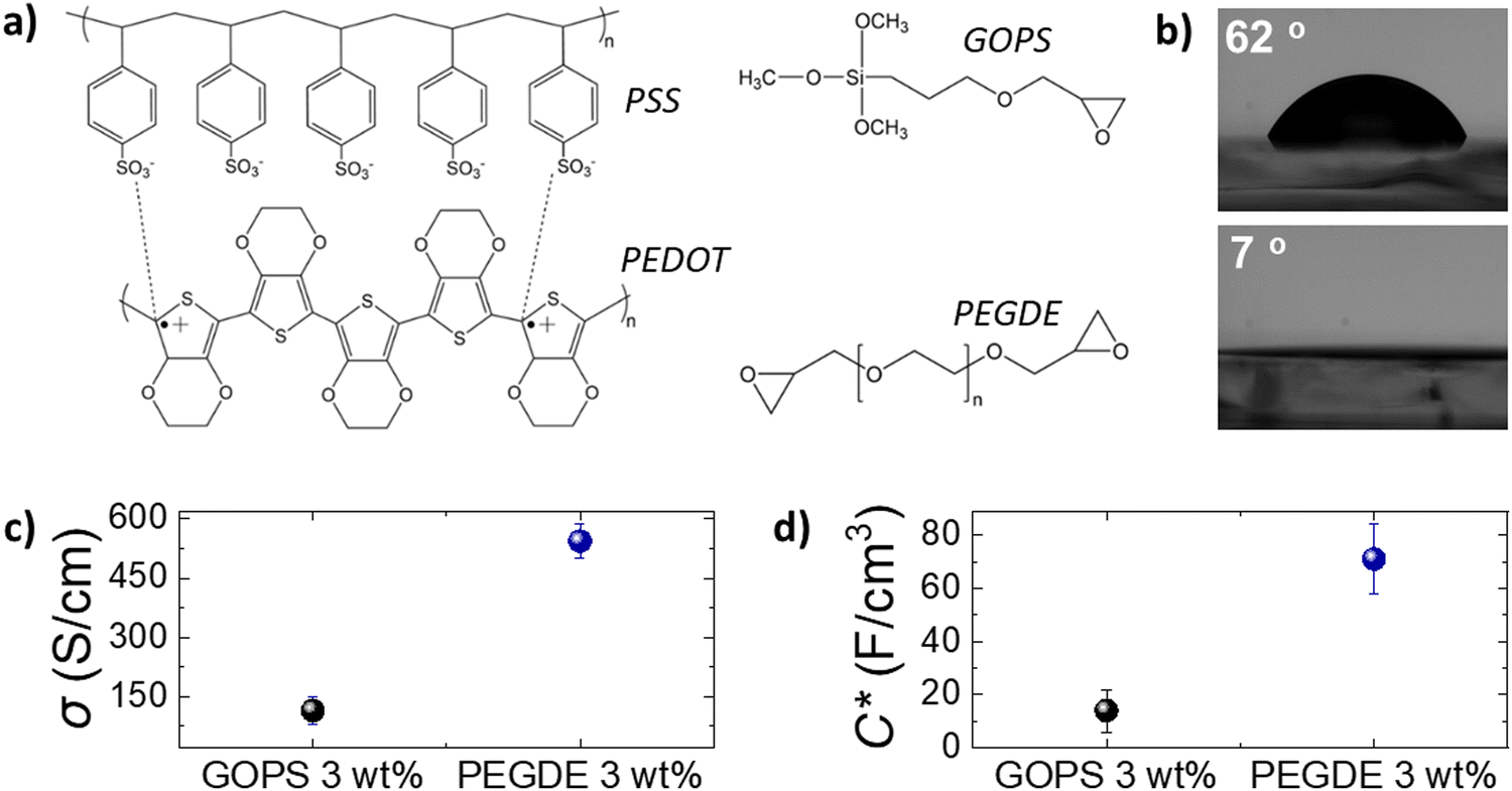 | ||
| Fig. 1 (a) The chemical structures of the conducting polymer PEDOT:PSS and the crosslinkers (3-glycidyloxypropyl)trimethoxysilane (GOPS) and poly(ethylene glycol)diglycidyl ether. (b) Digital pictures of the water contact angle on top of a PEDOT:PSS film crosslinked with GOPS 3 wt% (top) and with PEGDE 3 wt% (bottom). (c) Electrical conductivity (σ) and (d) volumetric capacitance (C*) of PEDOT:PSS films crosslinked with GOPS 3 wt% and PEGDE 3 wt%. Error bars represent the standard deviation of six replicates for each condition (mean ± SD, n = 6). | ||
To accurately characterize the electrochemical properties of PEDOT:PSS films, we used both micro-fabricated organic electrochemical transistors (OECTs) and electrodes. By using current-voltage measurements of PEDOT:PSS OECT channels of controlled thickness (Fig. S1, ESI†), we calculated the electrical conductivity of PEDOT:PSS films crosslinked with PEGDE (3 wt%) at 544 S cm−1 and with GOPS (3 wt%) at 125 S cm−1 (Fig. 1c). Furthermore, by using electrochemical impedance spectroscopy (EIS) measurements (Fig. S1, ESI†), we found that the volumetric capacitance of PEDOT:PSS films crosslinked with PEGDE (3 wt%) is 71 F cm−3 and with GOPS (3 wt%) is 14 F cm−3. These results show that PEGDE crosslinked PEDOT:PSS thin films exhibit superior electrochemical properties compared with GOPS crosslinked PEDOT:PSS thin films. However, we should note that the typical PEDOT:PSS crosslinking formulation that is used for thin bioelectronic devices is GOPS (1 wt%), with electrical conductivity values in the range of 400 S cm−126 and volumetric capacitance of 39 F cm−3.33 We found that the OECT transconductance (gm) is higher for PEDOT:PSS channels crosslinked with PEGDE (3 wt%) compared with PEDOT:PSS channels crosslinked with the standard GOPS (1 wt%) (Fig. S2, ESI†). Overall, PEDOT:PSS crosslinked with PEGDE (3 wt%) shows superior electrochemical properties compared with both GOPS (3 wt%) and GOPS (1 wt%) crosslinked PEDOT:PSS films. However, it is important to mention that PEGDE crosslinked PEDOT:PSS thin films delaminate from the glass substrates after a few days of operation in cell culture conditions (Fig. S3, ESI†). We attribute this to the absence of silanes groups in the PEGDE molecule (in contrast to GOPS), which react with glass substrates and allow PEDOT:PSS to be strongly attached on a glass support for long-term. Although we believe the PEGDE crosslinking strategy can potentially be used for the development of more sensitive thin film bioelectronic devices, further optimization of thin film devices is beyond the scope of this study.
We then fabricated PEDOT:PSS-based porous scaffolds crosslinked with different concentrations of GOPS and PEGDE via the freeze-drying technique. Both GOPS and PEGDE result in robust and stable 3D structures that maintained their shape for more than six months immersion in aqueous electrolytes (Fig. S4, ESI†). However, we found that the choice of the crosslinker regulates scaffold properties that are important for cell growth such as water retention (Fig. 2a), elasticity (Fig. 2b) and pore size (Fig. 2c). The water retention ability of 3D scaffolds used as hosts for tissue growth is an essential property that regulates cell media penetration and impacts cell proliferation. As shown in Fig. 2a, we found that PEDOT:PSS scaffolds crosslinked with GOPS (3 wt%), PEGDE (1 wt%) and PEGDE (3 wt%) retain substantial amounts of water – mean values 1712%, 1744%, 1777%, respectively. In contrast, the water retention ability is significantly reduced to a mean value of 327% and 213% for scaffolds crosslinked with PEGDE (5 wt%) and PEGDE (10 wt%), respectively (Fig. S5, ESI†). We also measured the mechanical properties of PEDOT:PSS scaffolds crosslinked with both GOPS (3 wt%) and PEGDE (3 wt%) and calculated a mean Young's modulus of 32.2 KPa and 17.9 KPa, respectively (Fig. 2b). These results show PEDOT:PSS scaffolds crosslinked with PEGDE are more elastic compared with those crosslinked with GOPS. The molecular structures and mechanisms of crosslinking of both GOPS and PEGDE can explain these observations: in GOPS crosslinked PEDOT:PSS, PSS chains are interconnected with an intermediate/rigid silyl ether bond formed between two GOPS molecules. In contrast, in PEGDE crosslinked PEDOT:PSS, PSS chains are directly interconnected with a single PEGDE molecule, which leads in more flexible bonds, and therefore, lower Young's modulus.
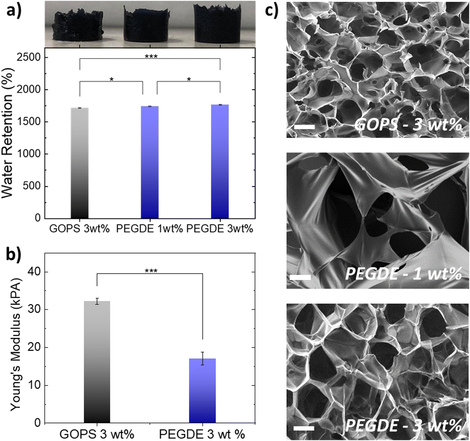 | ||
| Fig. 2 (a) Water retention ability of PEDOT:PSS-based scaffolds crosslinked with GOPS 3 wt%, PEGDE 1 wt% and PEGDE 3 wt% with a corresponding digital image of each (left to right). The plot shows water retention percentage of the different scaffolds after swelling in DI water. (b) Young's moduli for PEDOT:PSS scaffolds crosslinked with GOPS 3 wt% and PEGDE 3 wt% extracted from compression tests. The statistical significance between samples was evaluated using one-way ANOVA – *p < 0.05. Error bars represent the standard deviation of six replicates for each condition (mean ± SD, n = 6). (c) Scanning electron microscopy measurements of scaffolds prepared with different crosslinkers. Scale bars = 100 μm. | ||
We also examined the pore morphology of all the different PEDOT:PSS-based scaffolds using scanning electron microscopy (SEM), as shown in Fig. 2c. PEDOT:PSS scaffolds crosslinked with GOPS (3 wt%) exhibit an average pore size in the range of ∼50–100 μm, with anisotropic pore architecture, in agreement with previously reported studies. In contrast, PEDOT:PSS scaffolds produced with PEGDE show larger average pore size, in the range of ∼100–150 μm. When the concentration of PEGDE crosslinker is further increased to more than (5 wt%), the scaffolds show no porosity (Fig. S5, ESI†), which can also explain the significant reduction of water retention observed in Fig. S5 (ESI†) for such high PEGDE concentrations. We also used a mixture of GOPS and PEGDE crosslinkers to produce PEDOT:PSS 3D structures, with interconnected porous network of different sizes. The differences in pore size and architecture when different crosslinkers are used, are also visible in larger area SEM images shown in Fig. S6 (ESI†). Overall, all the PEDOT:PSS-based scaffolds produced with the different crosslinkers, concentrations and mixtures (except PEGDE higher than 5 wt%) exhibit highly open anisotropic pore architecture with average pore sizes suitable for cell penetration and growth.
We then integrated these PEDOT:PSS-based porous structures into 3D bioelectronic devices. We chose to proceed with PEDOT:PSS crosslinked with PEGDE (3 wt%) for two main reasons. First, the superior electrical properties of PEGDE crosslinked PEDOT:PSS (Fig. 1) could lead to devices with higher sensitivity. Second, the mechanical properties, combined with larger pore size of PEGDE crosslinked PEDOT:PSS scaffolds are more suitable for human adipose derived stem cell (hADSC) cultures. As shown in Fig. S7 (ESI†), individual stem cells grown in flat well plates show elongated shape with the long axis ranging between 200 μm and 400 μm, in line with previously published studies.34
The fabrication process of the 3D bioelectronic devices we used, is shown in Fig. 3a and b. First, PEDOT:PSS scaffolds were sliced using a vibratome to produce scaffolds slices of controlled thickness (250 μm – Fig. 3a) and homogeneous pore size distribution. These highly porous slices were then attached on Indium-Tin Oxide (ITO) transparent conducting substrates with the help of an adhesion layer—a PEDOT:PSS thin film with GOPS crosslinker used to attach the PEDOT:PSS scaffold slice. The device was finalized with the attachment of a circular mask (i.e. Kapton® tape – diameter = 7 mm) used to define the device active area at 0.39 cm2 followed by the attachment of a glass well to contain cells and cell media as will be discussed later.
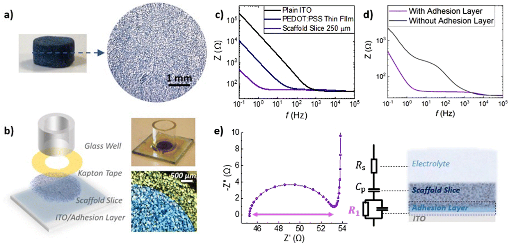 | ||
| Fig. 3 (a) Digital pictures of a PEDOT:PSS scaffold and a 250 μm thick scaffold slice made of PEDOT:PSS crosslinked with PEGDE 3 wt%. (b) Schematic of the 3D bioelectronic device developed in this study and as shown in the digital picture on the top right. A top view of the edge of this device is shown in the bottom left microscope image. The electrochemical area of the device is well defined by the micro-patterned Kapton tape. (c) Impedance magnitude versus frequency plots for the devices bearing the same electrochemical area as defined by the Kapton tape with plain ITO (black), ITO/adhesion layer (blue) and with the scaffold slice attached (purple). (d) A typical impedance versus frequency plot obtained for a 3D device that uses and adhesion layer to electrically connect the scaffold slice on ITO (purple) and for 3D device without an adhesion layer used (grey). (e) A typical Nyquist plot of an optimized ITO/adhesion layer/scaffold slice device and the equivalent circuit model used to raw EIS data. | ||
As shown in Fig. 3b, the impedance magnitude is compared for plain ITO, ITO/adhesion layer and ITO/adhesion layer/scaffold slice devices of the same area (0.39 cm2). We observe a striking drop of the impedance magnitude at low frequencies (i.e. ∼0.1 Hz–100 Hz) for the ITO/adhesion layer devices compared with the plain ITO devices and a further decrease of the impedance magnitude for the ITO/adhesion layer/scaffold slice devices. Since PEDOT:PSS capacitance scales with volume.35–37
The striking drop of the impedance magnitude in the low frequency regime can be attributed to the electrical connection of the 250 μm thick porous PEDOT:PSS scaffold slice with the conducting ITO substrate. To quantify these changes, we calculated the overall capacitance of the system at 0.1 Hz to be 168 μF cm−2, 358 μF cm−2, and 7692 μF cm−2 for plain ITO, ITO/adhesion layer and ITO/adhesion layer/scaffold slice devices, respectively. These results prove that the scaffold is well electrically connected on the ITO substrate and promotes the importance of the adhesion layer. As shown in Fig. 3d, a scaffold slice that was simply mechanically pressed on the ITO substrate (named as “without adhesion layer”) shows high impedance in frequencies below 1000 Hz. In contrast, when an adhesion layer is used the impedance magnitude is significantly smaller at this frequency range. The latter can be attributed to a good electrical connection of the scaffold slice on the ITO substrate. The characteristic semicircle of the 3D devices can be seen in the Nyquist plot graph in Fig. 3e, together with the equivalent circuit model used to fit the experimental data. We used a resistor element for the electrolyte resistance (RS), in series with a capacitor for PEDOT:PSS (CP), and with an R1–C1 circuit element for the crucial PEDOT:PSS/ITO interface. The quality of this interface is crucial for charge extraction from PEDOT:PSS to the ITO, and therefore, R1 can be used as a figure of merit to describe the charge transfer at this interface. As shown in Fig. 3e, R1 can be easily calculated by the absolute magnitude of the semicircle formed in the Nyquist plot representation of impedance data (i.e. subtraction of the absolute values that the semicircle intersects the x-axis). Based on all the above, the use of the adhesion layer between the ITO and the PEDOT:PSS scaffold slice, drastically improves charge collection and minimizes R1 between 5–20 Ohm as calculated from more than 10 individual devices. We also note that we have obtained similar frequency dependent impedance profile for devices constructed with different scaffold slice thicknesses. As shown in Fig. S7 (ESI†), a device made with a 400 μm thick scaffold slice shows the characteristic semicircle with R1 calculated at 9 Ohm.
The establishment of reproducible and characteristic impedance spectra allowed the monitoring of cell-related changes with impedance measurements The transparency of the ITO substrates together with the high porosity of the PEDOT:PSS scaffold also facilitates monitoring of cell growth via confocal microscopy. As shown in Fig. 4a–c, fluorescence images obtained from a live/dead viability assay proved that a healthy stem cell culture developed within the 3D PEDOT:PSS-based devices 10 days after seeding. We observed that after 2 days in culture (Fig. 4a) stem cells adhere and grow within the scaffolds, and by day 10 (Fig. 4b and c) have fully colonized the scaffold. Regimes where cells grow around the PEDOT:PSS scaffold pores can be also seen in Fig. 4b and a stem cell network that is developed in all directions and on different planes can be seen in Fig. 4c. To further assess cell morphology and proliferation within the proposed 3D devices, we applied immunofluorescence staining assays – β-tubulin-III (red) to probe cell morphology, and HOECHST (blue) to probe cell nuclei. As shown in Fig. 4d–f, hADSCs have colonized the scaffolds and form 3D cell networks after 10 days in culture.
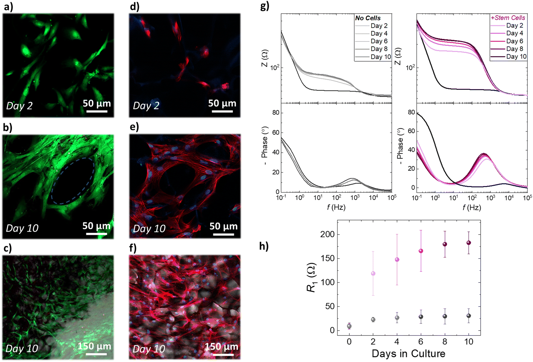 | ||
| Fig. 4 (a)–(c) Live/Dead assays stained with calcein AM (green – live cells) and ethidium homodimer-1 (red – Dead cells), and (d)–(f) immunofluorescence staining assays for cell cytoskeleton (red) and nuclei (blue) of human adipose derived stem cells cultures grown within the proposed bioelectronic devices, using PEDOT:PSS scaffold crosslinked with PEGDE 3 wt%. The fluorescence images in (c) and (d) are overlapped with bright filed images that reveal the pore architecture of the PEDOT:PSS-based 3D devices. (g) The impedance magnitude and the phase of the impedance obtained every 2 days for overall 10 days for identically prepared devices, without (black/grey) and with (pink/purle) being seeded with hADSCs (h) the interface resistance (R1) extracted as a figure of merit and plotted as a function of days monitoring the stem cell tissue growth for control devices (black circles) and for devices that have been seeded with hADSCs (purple). Error bars represent the standard deviation of five device replicates for each condition (mean ± SD, n = 5). | ||
We estimated the number of cells per unit area, by counting the number of cell nuclei in immunofluorescence images obtained from several scaffold slices, at different planes and different magnification. After 2 days in culture, the scaffold slices host approximately 21![[thin space (1/6-em)]](https://www.rsc.org/images/entities/char_2009.gif) 000 cells per cm2. Following the same approach, we found that after 10 days in culture the scaffold slices hosted approximately 61000 cells per cm2. These studies show that stem cells grown within the PEDOT:PSS scaffold preserve a similar elongated shape compared with the cells grown in control well-plates (Fig. S8, ESI†). Importantly, 3D cell growth is supported by the conducting polymer scaffold and represents a significantly more realistic in vitro model for stem cell studies – as revealed by the combined immunofluorescence and bright filed microscopy images in Fig. 4f and Fig. S9 (ESI†). In addition, it is worth noting that the proposed conducting scaffolds are compatible with other 3D cell line cultures. As shown in Fig. S10 (ESI†), we used PEGDE-3wt% – PEDOT:PSS scaffolds to grow rat fibroblast and rat epithelial cell networks in 3D. Overall, these results prove that the proposed conducting scaffolds are highly cyto-compatible and biomimetic and reveal their potential to be used as platforms for several in vitro cell models. The electroactive properties of the PEDOT:PSS-based scaffold slices were leveraged to monitor the increase in stem cell population using impedance measurements. As shown in Fig. 4e, we monitored the impedance spectra changes of devices that have been seeded with hADSCs for 10 days. The impedance magnitude showed a distinct increase at the frequency range ∼1 Hz–1000 Hz over the period of 10 days in culture, which is also associated with an increase of the impedance phase (Fig. 4e). These changes are also distinct in the characteristic semicircle of the Nyquist plots (discussed earlier in Fig. 3) as shown in Fig. S11 (ESI†). In contrast, the impedance magnitude, and the phase of the impedance of identically prepared devices that have not been seeded with stem cells show only a slight increase in the range of frequency ∼1 Hz–1000 Hz (Fig. 4f). As expected from the raw impedance data (Fig. 4e, f and Fig. S8, ESI†), we found that R1 drastically increases for the devices seeded with hADSCs i.e. from 9 Ω before seeding to 119 Ω at day 2 to 183 Ω at day 10. In contrast, The devices that have not been seeded with hADSCs show a slight increase in R1 during the 10 day period of incubation (from 10 Ω on day 0 to 31 Ω at day 10). We suggest that the increase in R1 can be correlated with the increase in stem cell population within the PEDOT:PSS scaffolds. Based on our approximation of the population of cells within the 3D scaffolds presented in the previous paragraph, we can correlate the increase of ∼40000 cells per cm2 in the 3D scaffolds, with the increase of ∼60 Ω in R1 extracted from the impedance measurements on 3D devices, from day 2 to day 10 in culture. Overall, our fluorescence microscopy studies show that stem cells proliferate and colonize scaffolds in all directions—an event that can disrupt the ion flow between the electrolyte and the conducting scaffold network and increase the impedance of the system. Moreover, the inclusion of stem cells within the pores of PEDOT:PSS structure affects the crucial interface between the PEDOT:PSS scaffold slice and the ITO surface and impedes the charge transfer. Therefore, our proposed devices serve as a facile platform to monitor stem cells proliferation with conventional electrical measurements.
000 cells per cm2. Following the same approach, we found that after 10 days in culture the scaffold slices hosted approximately 61000 cells per cm2. These studies show that stem cells grown within the PEDOT:PSS scaffold preserve a similar elongated shape compared with the cells grown in control well-plates (Fig. S8, ESI†). Importantly, 3D cell growth is supported by the conducting polymer scaffold and represents a significantly more realistic in vitro model for stem cell studies – as revealed by the combined immunofluorescence and bright filed microscopy images in Fig. 4f and Fig. S9 (ESI†). In addition, it is worth noting that the proposed conducting scaffolds are compatible with other 3D cell line cultures. As shown in Fig. S10 (ESI†), we used PEGDE-3wt% – PEDOT:PSS scaffolds to grow rat fibroblast and rat epithelial cell networks in 3D. Overall, these results prove that the proposed conducting scaffolds are highly cyto-compatible and biomimetic and reveal their potential to be used as platforms for several in vitro cell models. The electroactive properties of the PEDOT:PSS-based scaffold slices were leveraged to monitor the increase in stem cell population using impedance measurements. As shown in Fig. 4e, we monitored the impedance spectra changes of devices that have been seeded with hADSCs for 10 days. The impedance magnitude showed a distinct increase at the frequency range ∼1 Hz–1000 Hz over the period of 10 days in culture, which is also associated with an increase of the impedance phase (Fig. 4e). These changes are also distinct in the characteristic semicircle of the Nyquist plots (discussed earlier in Fig. 3) as shown in Fig. S11 (ESI†). In contrast, the impedance magnitude, and the phase of the impedance of identically prepared devices that have not been seeded with stem cells show only a slight increase in the range of frequency ∼1 Hz–1000 Hz (Fig. 4f). As expected from the raw impedance data (Fig. 4e, f and Fig. S8, ESI†), we found that R1 drastically increases for the devices seeded with hADSCs i.e. from 9 Ω before seeding to 119 Ω at day 2 to 183 Ω at day 10. In contrast, The devices that have not been seeded with hADSCs show a slight increase in R1 during the 10 day period of incubation (from 10 Ω on day 0 to 31 Ω at day 10). We suggest that the increase in R1 can be correlated with the increase in stem cell population within the PEDOT:PSS scaffolds. Based on our approximation of the population of cells within the 3D scaffolds presented in the previous paragraph, we can correlate the increase of ∼40000 cells per cm2 in the 3D scaffolds, with the increase of ∼60 Ω in R1 extracted from the impedance measurements on 3D devices, from day 2 to day 10 in culture. Overall, our fluorescence microscopy studies show that stem cells proliferate and colonize scaffolds in all directions—an event that can disrupt the ion flow between the electrolyte and the conducting scaffold network and increase the impedance of the system. Moreover, the inclusion of stem cells within the pores of PEDOT:PSS structure affects the crucial interface between the PEDOT:PSS scaffold slice and the ITO surface and impedes the charge transfer. Therefore, our proposed devices serve as a facile platform to monitor stem cells proliferation with conventional electrical measurements.
Monitoring 3D adult stem cell growth in vitro with non-destructive, electrical measurements could be a significant advantage for stem cell engineering. Most stem cell therapies that are currently developed, rely on 3D stem cell growth and subsequent differentiation to specific cell types. The degree of stem cell growth affect the quality, and the yield, of stem cell differentiation to different cell types.38 Having established a device that allows for monitoring stem cells growth without affecting the culture, we moved one step further and used these 3D devices as platforms for stem cell differentiation. We established an hADSC neurogenic differentiation pathway, differentiating hADSCs into neuron-like cells. This protocol was initially optimized on 2D PEDOT:PSS films. As shown in Fig. 5a and b, hADSCs show a distinct morphological change when treated with neurogenic differentiation media. To verify the cell phenotype after differentiation we performed immunofluorescence imaging for several neuronal markers, namely β-tubulin III (TUBB3)and neurofilament light chain (NEFL) – Fig. 5 – as well as microtubule-associated protein 2 (MAP-2) and neuronal nuclear protein (NeuN) – Fig. S12 (ESI†). In line with previously reported studies, we found that TUBB3, MAP-2 and NeuN arestrongly expressed in undifferentiated hADSCs as well as differentiated, neuron like cells. In fact, several other neuronal markers are found to be expressed in undifferentiated hADSCs (e.g. SOX-2, Nestin).39,40 Importantly, our studies showed that NEFL was expressed in neuron-like cells derived from hADSCs, but not strongly expressed in undifferentiated cells (Fig. 5b). Neurofilaments are a major constituent of the cytoskeletal scaffold of several neuron types41 – mostly found in axons, but also found in cell bodies, dendrites, and synapses in smaller amounts.42 The commitment of hADSCs into neuronal phenotype is verified by mRNA expression of TUBB3 and NEFL, which was measured by means of RT-qPCR in undifferentiated and differentiated hADSC. Data were normalized to the housekeeping genes GAPDH and ACTβ. Undifferentiated cells were used as a reference control for fold change calculations. In line with the fluorescence measurements, the NEFL gene is expressed only in differentiated cells and not detected in undifferentiated cells. The GFAP gene – a common marker for astrocytes – was not detected by means of of RT-qPCR (data not shown), indicative of the absence of astrocytes from the cultures. We then applied this neurogenic differentiation protocol in our proposed 3D platforms. As shown in Fig. 5c, hADSCs grow in 3D follow the pattern and the pore morphology of the PEDOT:PSS scaffolds. These results were observed on both free floating PEDOT:PSS scaffolds (Fig. 5d) as well as on fully mounted 3D bioelectronic devices that were able to monitor stem cell proliferation as described in Fig. 4. After day 8 cells have fully colonized the scaffolds and neurogenic differentiation was induced in 3D (Fig. S13, ESI†). A significant, 3D morphological change of the cells as well as NEFL were also observed in neuron-like cells (Fig. 5d), verifying the commitment of hADCSs into a neuronal differentiation pathway.
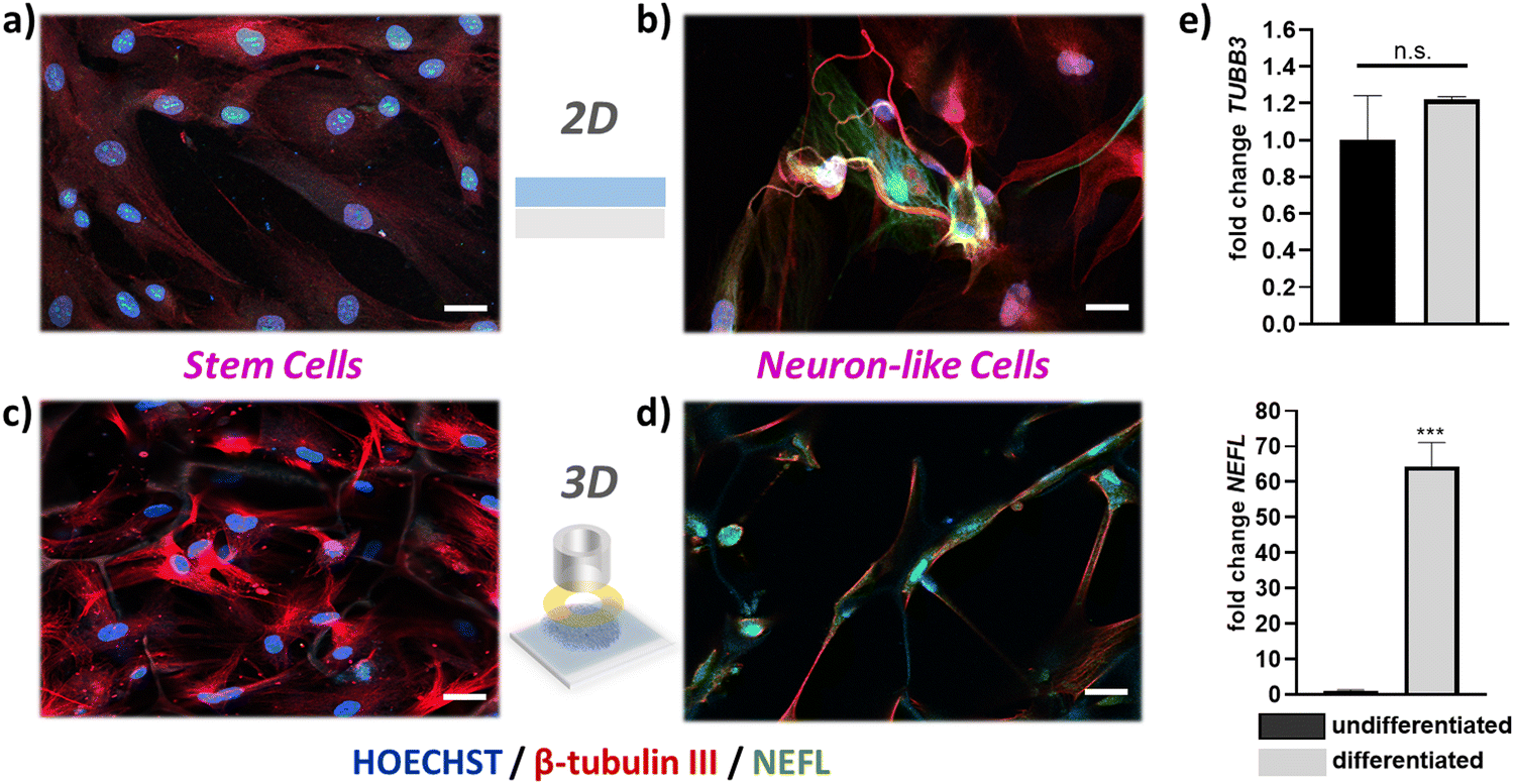 | ||
| Fig. 5 Immunofluorescence images of 2D cultures on PEDOT:PSS films of (a) human adipose derived stem cells cultured on PEDOT:PSS thin films. (b) neuron-like cells derived from hADSCs. (c) Immunofluorescence images of 3D cultures in PEDOT:PSS:PEGDE-based electroactive devices of non-differentiated hADSCs, and (d) neuron-like cells derived from hADSCs. All cultures were stained for b-tubulin (in red), counterstained for neurofilament light chain (NEFL, in green), and for cell nuclei (HOECHST, in blue). Scale bars = 20 μm. (e) RT-qPCR results gene expression of TUBB3 and NEFL from undifferentiated hADSC cultures and neuron-like cell cultures derived from hADSCs. Statistical significance of 3 technical replicates was tested by parametric and non-parametric t-Test, p < 0.05, using GraphPad Prism 9.4.1. | ||
Conclusion
In summary, we showed the development of PEDOT:PSS-based electroactive porous scaffolds that are used as hosts for human stem cell cultures. We demonstrated that the mechanical, electrical and morphological properties of these scaffolds can be tailored by simply changing the crosslinking parameters, a significant advantage over other scaffold materials that are commonly used. PEDOT:PSS crosslinked with PEGDE shows excellent electrical conductivity, volumetric capacitance as well as hydrophilic properties. 3D porous structures made by this formulation via lyophilization, showed increased water retention ability, more elastic behavior and larger pore size distribution compared with the established GOPS crosslinking strategy. The porous network can also be controlled by using mixtures of crosslinkers – a feature that can be exploited to tailor scaffold properties for specific cell cultures. Furthermore, we reported the development of 3D bioelectronic devices with characteristic and reproducible electrochemical impedance signals. The use of an adhesion layer—a PEDOT:PSS thin film with GOPS crosslinker used to electrically attach the PEDOT:PSS scaffold slice on ITO substrates – minimizes the interface resistance (R1) between the scaffold slice and the ITO substrate. These devices supported the adhesion and growth of viable hADSCs cultures over 10 days, as revealed by viability assays. The electrical properties of the device and the PEDOT:PSS scaffolds are utilized to monitor stem cell growth with non-invasive impedance measurements. The device impedance signature signal changes upon stem cell proliferation which is correlated with in situ fluorescence imaging of the stem cells tissue. This change is quantified by calculating the increase of the interface resistance caused by inclusion of the cells in the scaffold's pores. When stem cells colonize the scaffolds – which can be observed by the increase of device R1 – we applied a neurogenic differentiation protocol to induce neuron-like cells, as verified by the detection of NEFL, a neuronal biomarker that is present in the axons, soma and dendrites of neurons. These results proved that the proposed 3D devices serve as highly biocompatible platforms for 3D stem cell differentiation.In conclusion, the strategy of controlling important properties of 3D PEDOT:PSS structures shown here, can be applied for development of a number of stem cell in vitro models. Our approach provides flexibility in 3D device design, with different scaffold sizes and shapes, which can be in the future be tuned for specific stem cell engineering applications. Further development of these platforms can also have added features, such us using the bioelectronic properties of the scaffolds to stimulate stem cell cultures aiming for controlled cell-fate direction. We believe the results presented will facilitate further advancements in 3D bioelectronic technology. More specifically tailored 3D bioelectronic devices for stem cell research can be proved useful tools for both fundamental understanding of in vitro stem cell engineering as well as for advancing the development of stem cell-based regenerative therapies.
Experimental
Materials
PEDOT:PSS Clevios PH – 1000 was purchased from Heraeus GmbH. (3-glycidyloxypropyl)trimethoxysilane – GOPS (product no. 440167), poly(ethylene glycol) diglycidyl ether -PEGDE (product no. 475696), ethylene glycol (product no. 324558), sodium dodecylbenzenesulfonate – DBSA(product no. 44198) and glass wells (product no. CLS316610) were purchased from Sigma-Aldrich.Contact angle measurements
Water contact angles were measured on thin films of PEDOT:PSS with a KRUSS DSA 100E goniometer by using the sessile drop method. All measurements were taken 5 seconds after the water drop deposition on each films in a cleanroom environment with constant relative humidity of 45% following the recommendation by C. Duc et al.432D device micro-fabrication
We fabricated PEDOT:PSS-based OECT arrays with three OECTs 50 μm × 50 μm channels, and three OECTs 100 μm × 100 μm channels, as follows: 4 inch glass wafers first were cleaned by sonication in an acetone and then Isopropanol for 15 minutes in each step. The wafers were rinsed with DI water and baked for 15 min at 150 °C. To pattern for contact tracks, a negative photoresist, AZ nLOF2035 (Microchemicals GmbH) was spun on the glass wafer with 3000 rpm for 45 s and exposed with UV light using mask aligner (Karl Suss MA/BA6). The photoresist was developed in AZ 726 MIF developer (MIcroChemicals) developer for 28 s. The conducting tracks were made of Ti (5 nm)/Au (100 nm) and were deposited by e-beam evaporation on top of the clean wafers. The Ti–Au metal layer was lifted-off by soaking in NI555 (Microchemicals GmbH) overnight. Prior to the deposition of a 2 μm layer (sacrificial layer) of parylene C ((SCS), the wafer is soaked with 3% A174 (3-(trimethoxysilyl)propyl methacrylate) in ethanol solution (0.1% acetic acid in ethanol) for 60 seconds to promote the parylene C adhesion on the wafer. An anti-adhesive layer of Micro-90 in DI water (2% v/v solution) was spun (1000 rpm for 45 seconds), and then the second layer of 2 μm parylene C (SCS) was deposited. A layer of positive photoresist AZ 10XT (Microchemicals GmbH) was spun with 3000 rpm for 45 s and developed in AZ 726 MIF developer (MicroChemicals) for 6 min to pattern OECT channel. Reactive ion etching (Oxford 80 Plasmalab plus) was used to open the window for deposition of either Clevios PH1000 PEDOT:PSS (Heraeus). The PEDOT:PSS solution was mixed with 5 vol% ethylene glycol, 0.26 vol% dodecylbenzenesulfonic acid (DBSA), and 1–3 vol% (3-glycidyloxypropyl)trimethyloxy-silane (GOPS) or 1–3% PEGDE. The final solutions were spin-coated at 3000 rpm for 45 s. The samples were initially baked at 90 °C for 1 min, followed by peeling off the sacrificial layers. Finally, the samples were annealed on a hot plate at 130 °C and soaked in water overnight before used. The thicknesses of PEDOT:PSS thin films were measured using a VEECO stylus profilometer.2D device characterization
OECTs were characterized using a dual-channel source-meter unit (NI-PXI) with custom-written control code in LabVIEW. All measurements were performed using an Ag/AgCl pellet (D = 2 mm × H = 2 mm – Warner instruments) as the gate electrode. Phosphate buffered saline (PBS) was placed in a PDMS well on top of the OECTs at a constant volume (150 μL). The frequency dependent response of the transconductance was extracted using a method described previously by Rivnay et al.2 Electrochemical impedance spectroscopy (EIS) measurements were performed using a PG128N Metrohm-Autolab potentiostat, with a standard three-electrode setup in PBS(aq.) 1 X. The films were addressed as the working electrode, while a Pt mesh and Ag/AgCl were used as the counter and reference electrode, respectively. EIS was performed at a frequency range between 100 kHz to 0.1 Hz at V = 0 V vs. VOC with an AC amplitude of 10 mV. We extracted the volumetric capacitance value for each system by determining the value of capacitance at 0.1 Hz using eqn 1 and dividing it with the film volume (area x thickness): | (1) |
PEDOT:PSS macro-porous scaffolds and slices
Scaffolds were fabricated from an aqueous dispersion of PEDOT:PSS (Clevios PH-1000, Heraeus) at a concentration of 1.2 wt%, using the freeze drying process.11 The different PEDOT:PSS solution formulations were prepared as follows: 5 mL of PEDOT:PSS PH1000 solution was first filtered with 0.8 μm cellulose acetate filters. Then 26 μL of DBSA (0.5 wt%) and different amount of crosslinkers, i.e. 150 μL of GOPS (3 wt%), PEGDE 50–500 μL (1–10 wt%) or a mixture of 75 μL GOPS and PEGDE 75 μL (1.5:1.5 wt%) were added in the solution followed by sonication at room temperature for 10 minutes. The different PEDOT:PSS solution formulations were poured into either 24, 48 or 96 well-plates that were used as molds for producing macro-porous scaffolds of different dimensions. The well-plates were placed in the freeze-dryer (Virtis AdVantage 2.0 BenchTop from SP Scientific) and frozen from 5 to −30 °C at a controlled cooling rate, after which point the ice phase was sublimed from the scaffolds. The samples were then removed and dried at 80 °C for 4 h. PEDOT:PSS scaffold slices of controlled thickness were produced by slicing the bulky scaffolds with a LEICA VT1200S micro-vibratome with a blade speed of 0.8 mm s−1 and a vibration amplitude of 1 Hz. It is noted here that through the optimization of cell culture and 3D device fabrication, a wide range of scaffold slice thicknesses were used – between 100–500 μm.
Water retention measurements
The water retention percentage for each of the PEDOT:PSS scaffold formulations was calculated using the following equation after weighing the scaffolds at dry conditions (directly after freeze dried and annealed) and after immersing the scaffolds in DI water for 24 h. An analytical balance with 0.1 mg resolution was used.
Six different scaffolds were used to calculate the water retention percentage for each formulation. All scaffolds used for the results presented in Fig. 2 made in the same freeze batch within 98 well-plate. Similar results were obtained from another 2 identically executed experimental runs.
Young's modulus
PEDOT:PSS scaffolds were characterized mechanically using compression tests (Tinius Olsen Ltd) 1–50 kN. With a Tinius Olsen apparatus, the compressive moduli of the dry scaffolds was calculated. The Tinius Olsen had a load cell of 25 N and the compression speed was set at 1 mm min−1. Young's modulus values were calculated from the slope of the linear part of the stress–strain curves for each scaffold.Scanning electron microscopy
The microstructure and surface morphology of the scaffolds were analyzed using Scanning electron microscopy (Leo Variable pressure SEM, ZEIS GmbH). The samples were mounted on conductive adhesion tape and analyzed at 1 kV power and the beam current was maintained at 50 pA.Cell culture and cell seeding
Human adipose-derived stem cells (Lonza – PT-5006) were grown in T-75 flasks in Dulbecco's modified Eagle medium – high glucose (Sigma – D5671) supplemented with Fetal Bovine Serum (Gibco-F9665), 2 mM GlutaMax (Gibco-35050061) and 100 U mL−1 Penicillin-Streptomycin (Gibco-15070063). Prior to cell seeding, scaffolds or devices were immersed into ethanol 70 vol% for at least 1 h for sterilization and then transferred in a sterilized laminar flow hood and washed three times with sterile water and three times with sterile PBS. The devices were then immersed in cell media and left in a humidified incubator at 37 °C with 5% CO2 for 2 days to ensure media penetration within the pores. After the 2 days media incubation, a reference EIS spectra was measured and 50000 cells per cm2 suspended in 20 μL of complete media were added on top of the devices and incubated for 2 hours to allow the cells to adhere. After the 2 hour period the devices were transferred back into a sterilized laminar flow hood and 280 μL of media were added in the glass wells. The devices were then incubated for several days, and fresh media were added every 2 days, after every EIS measurement. 3D cell growth of primary cells within PEGDE-based PEDOT:PSS scaffolds was performed as follows: 600000 208F cells, Rat Fibroblast (ECACC, 85103116) and 700000 IEC-6, rat small intestine epithelial cells (ECACC, 88071401) were seeded on the apical side of the PEDOT:PSS scaffolds slices under immersed conditions for 21 days, and 15 days, respectively.
3D bioelectronic device fabrication and characterization
ITO substrates were sonicated in acetone and dried with a nitrogen gun. The adhesion layer was deposited on the clean ITO substrates by spin coating a PEDOT:PSS PH 1000 solution with 2 wt% GOPS at 1000 rpm for 45 seconds followed by soft annealing at 90 °C for 30 seconds. Then, a wet scaffold slice was gently attached on the PEDOT:PSS adhesion layer and both layers were annealed at 110 °C for 1 h. For all data shown in the main manuscript, we used 250 μm thick scaffold slices (Fig. 3, 4 and 5). A micro-patterned kapton tape with a ring opening of 7 mm was attached on the surface of the devices, to accurately define the exposed slice area (0.385 cm2). Finally, a glass well was attached on the device using PDMS as a glue (SYLGARD™ 184 silicone elastomer Kit) and dried overnight at room temperature. After dried, the devices were left in DI water for multiple days and until used. Electrochemical impedance spectroscopy measurements were performed with an Autolab PGSTAT204 by Metrohm AG. An Ag/AgCl/KCL 3 M was used as reference and a Pt mesh was used as counter electrode, both immersed in 300 μL of electrolyte (either PBS 1X or cell media). A tungsten pin was used to contact the ITO substrate and served as the working electrode. All electrodes were sterilized with ethanol 70 vol% prior to EIS measurements which were performed in a sterilized laminar flow hood to avoid contamination. The control devices without cells were kept in the same media used to grow hADSCs and kept in an incubator at 37 °C with 5% CO2.Live/dead assay
Cell viability was performed using the LIVE/DEADTM Viability/Cytotoxicity Kit (Invitrogen) at different time points of the cell culture between day 2 and day 10. This assay permits to assess live and dead cells in vitro by means of two fluorescence molecular probes (i.e. Calcein AM (green, live cells) and Ethidium Homodimer (EthD (red, dead cells), which are representative of intracellular esterase activity and plasma membrane integrity, respectively. The viability assay was performed using 2 μM calcein AM and 4μM EthD-1 in PBS. Scaffold slices were incubated for 45 min at room temperature with the reagents and then mounted on a cover slip for sample observation under the confocal microscope (ZEISS LSM 800). The same approach was followed to address the viability of hADCs within 3D bioelectronic devices.Neurogenic differentiation of hADSCs
Mesenchymal stem cell neurogenic differentiation medium was purchased from PromoCell (C-28015). For 2D cell cultures, hADSCs were seeded on flat PEDOT:PSS films and cultured for 3 days until they reached 60–80% confluency. On day 3, the neurogenic differentiation was induced by exchanging the growth media with neurogenic differentiation media (NDM) and kept for 3 days, before the cultures were fixed for either immunofluorescence imaging or lysed for RT-qPCR measurements. For 3D hADSCs cultures both free floating scaffolds as well as 3D bioelectronic devices were used. Devices and scaffolds were seeded with hADCSs and grown for 7 days, before neurogenic differentiation was induced. The cultures were kept in NDM for 3 days before being fixed, stained or lysed.Immunofluorescence imaging
All samples were fixed with 4% paraformaldehyde (PFA, Thermo Fisher Scientific) for 5 minutes (devices) or 15 minutes (scaffolds) at room temperature. Before immunostaining cells were permeabilized in 0.25% v/v Triton X-100 (Fisher Scientific) for 5 minutes (devices) or 10 minutes (scaffolds) at R.T. Cells were then blocked for nonspecific binding in 3%wt/v BSA (Fisher Scientific) and 0.1% v/v Tween -20 (Fisher Scientific) for 30 minutes (devices) or 1 hour (scaffolds). Cells were stained with the beta-3 Tubulin monoclonal antibody eFluor 660 (5 μg mL−1, Thermo Fisher) and Rabbit anti-NEFL monoclonal antibody (1:100, Thermo Fisher Scientific) overnight at 4 °C, the next day scaffolds were incubated with goat anti-rabbit AlexaFluor488 (4 μg mL−1, Thermo Fisher) for 1 hour (devices) or 2 hour (scaffolds) at R.T. and then counter stained with Hoechst (4 μm, AbCam) for 10 minutes (devices) or 20 minutes (scaffolds)
RT-qPCR measurement
A difference between gene expression in differentiated and undifferentiated hADSC was measured by RT-qPCR. RNA was isolated using TRIzol™ Reagent (Thermofisher, UK). RNA isolation, cDNA synthesis and PCR were done by using Monarch® Total RNA Miniprep Kit, LunaScript® RT SuperMix Kit and Luna® Universal qPCR Master Mix (New England BioLabs, UK). Primer pairs for target genes and housekeeping genes were obtained from SigmaAldrich, UK (KiCqStart® SYBR® Green Primers) and citation.44| Species | Gene | Gene ID | Forward 5′–3′ | Reverse 5′–3′ |
|---|---|---|---|---|
| Human | TUBB3 | 10381 | TCATCTTTGGTCAGAGTGG | GTTTTCACACTCCTTCCG |
| Human | NEFL | 4747 | CTAAAAGAATACCAAGACCTCC | ATAGGAGCTGGTCTGTAAAC |
| Human | ACTβ | 60 | AAGAGATGGCCACGGCTGCT | TCCTTCTGCATCCTGTCGGCA |
| Human | GAPDH | 2597 | GCACCGTCAAGGCTGAGAAC | ATGGTGGTGAAGACGCCAGT |
Real-Time PCR was carried out on an ABI Applied Biosystems 7500 Real-Time PCR System. RT-qPCR data were analyzed with LinRegPCR (version 2021.1)
Author contributions
A. S. conceived the research, performed contact angle measurements, fabricated the scaffolds, designed and fabricated the 3D devices, performed water retention measurements, performed EIS measurements, analyzed the results, performed cell culture and wrote the manuscript. J. S. C. performed Young's modulus measurements, assisted on scaffold fabrication and water retention measurements. J. S. C. and C. M. M. performed SEM measurements. SEK performed primary 3D cell cultures in conducting scaffolds and characterized them with immunofluorescence assays. C. B. and C. M. M. performed live/dead assays and confocal microscopy. V. S. performed RNA isolation, cDNA synthesis, and RT-qPCR measurements. Z. L. fabricated planar transistors and electrodes and performed OECT and EIS measurements with the assistance of K. K. A. W. assisted on cell culture and immunofluorescence images. C. P. assisted on scaffold fabrication. A. S. and R. M. O. designed the experiments and supervised the work. All authors discussed the results and assisted in manuscript input.Conflicts of interest
There are no conflicts to declare.Acknowledgements
A.S. acknowledges funding from the European Union's Horizon 2020 research and innovation program under the Marie Skłodowska-Curie grant, MultiStem (No. 895801). J.S. acknowledges funding from the European Union's Horizon 2020 research and innovation program under the Marie Skłodowska-Curie grant, ICE-METs (No. 842356). JS also acknowledges the Ikerbasque, Basque Foundation for Science, Departamento de Salud del Gobierno Vasco, FUNDACION Vital Fundazioa, Gobierno de España, Ministerio de Ciencia y Educación de España” under grant PID2020-120313 GB-I00/AIE/10.13039/501100011033, and Gobierno Vasco Dpto. Educación for the consolidation of the research groups (IT1633-22). C.B. and R.M.O. acknowledge funding from the European Research Council (ERC) under the European Union's Horizon 2020 research and innovation programme (grant agreement no. 723951). The authors also wish to acknowledge funding by the Engineering and Physical Sciences Research Council Centre for Doctoral Training in Sensor Technologies and Applications (EP/L015889/1 to CB).References
- W. Zakrzewski, M. Dobrzyński, M. Szymonowicz and Z. Rybak, Stem Cell Res. Ther., 2019, 10, 68 CrossRef CAS PubMed.
- K. Ronaldson-Bouchard, S. P. Ma, K. Yeager, T. Chen, L. Song, D. Sirabella, K. Morikawa, D. Teles, M. Yazawa and G. Vunjak-Novakovic, Nature, 2018, 556, 239–243 CrossRef CAS PubMed.
- D. J. Blackiston, K. A. McLaughlin and M. Levin, Cell Cycle, 2009, 8, 3527–3536 CrossRef CAS PubMed.
- K. Henderson, A. D. Sligar, V. P. Le, J. Lee and A. B. Baker, Adv. Healthcare Mater., 2017, 6, 1700556 CrossRef PubMed.
- G. Abagnale, M. Steger, V. H. Nguyen, N. Hersch, A. Sechi, S. Joussen, B. Denecke, R. Merkel, B. Hoffmann, A. Dreser, U. Schnakenberg, A. Gillner and W. Wagner, Biomaterials, 2015, 61, 316–326 CrossRef CAS PubMed.
- S.-B. Han, J.-K. Kim, G. Lee and D.-H. Kim, Adv. Biosyst., 2020, 4, 2000247 CrossRef PubMed.
- F. Pampaloni, E. G. Reynaud and E. H. K. Stelzer, Nat. Rev. Mol. Cell Biol., 2007, 8, 839–845 CrossRef CAS PubMed.
- J. Nicolas, S. Magli, L. Rabbachin, S. Sampaolesi, F. Nicotra and L. Russo, Biomacromolecules, 2020, 21, 1968–1994 CrossRef CAS PubMed.
- C. Pitsalidis, D. van Niekerk, C.-M. Moysidou, A. J. Boys, A. Withers, R. Vallet and R. M. Owens, Sci. Adv., 2022, 8, eabo4761 CrossRef CAS PubMed.
- C. Pitsalidis, M. P. Ferro, D. Iandolo, L. Tzounis, S. Inal and R. M. Owens, Sci. Adv., 2018, 4, 1–10 Search PubMed.
- C.-M. Moysidou, C. Pitsalidis, M. Al-Sharabi, A. M. Withers, J. A. Zeitler and R. M. Owens, Adv. Biol., 2021, 5, 2000306 CrossRef CAS.
- S. Inal, A. Hama, M. Ferro, C. Pitsalidis, J. Oziat, D. Iandolo, A.-M. Pappa, M. Hadida, M. Huerta, D. Marchat, P. Mailley and R. M. Owens, Adv. Biosyst., 2017, 1, 1700052 CrossRef.
- A. M. D. Wan, S. Inal, T. Williams, K. Wang, P. Leleux, L. Estevez, E. P. Giannelis, C. Fischbach, G. G. Malliaras and D. Gourdon, J. Mater. Chem. B, 2015, 3, 5040–5048 RSC.
- C. M. Moysidou, C. Barberio and R. M. Owens, Front. Bioeng. Biotechnol., 2021, 8, 620962 CrossRef PubMed.
- J. Qu, L. Ouyang, C. C. Kuo and D. C. Martin, Acta Biomater., 2016, 31, 114–121 CrossRef CAS PubMed.
- H. Zhang, Ice templating and freeze-drying for porous materials and their applications, John Wiley & Sons, 2018 Search PubMed.
- X. Zhang, C. Li and Y. Luo, Langmuir, 2011, 27, 1915–1923 CrossRef CAS PubMed.
- A. K. Jayaram, C. Pitsalidis, E. Tan, C.-M. Moysidou, M. F. L. De Volder, J.-S. Kim and R. M. Owens, Front. Chem., 2019, 7, 363 CrossRef CAS PubMed.
- I. del Agua, S. Marina, C. Pitsalidis, D. Mantione, M. Ferro, D. Iandolo, A. Sanchez-Sanchez, G. G. Malliaras, R. M. Owens and D. Mecerreyes, ACS Omega, 2018, 3, 7424–7431 CrossRef CAS PubMed.
- A. Håkansson, S. Han, S. Wang, J. Lu, S. Braun, M. Fahlman, M. Berggren, X. Crispin and S. Fabiano, J. Polym. Sci., Part B: Polym. Phys., 2017, 55, 814–820 CrossRef.
- G. Dijk, A. L. Rutz and G. G. Malliaras, Adv. Mater. Technol., 2020, 5, 1900662 CrossRef CAS.
- S. L. Bidinger, S. Han, G. G. Malliaras and T. Hasan, Appl. Phys. Lett., 2022, 120, 073302 CrossRef CAS.
- M. Solazzo, K. Krukiewicz, A. Zhussupbekova, K. Fleischer, M. J. Biggs and M. G. Monaghan, J. Mater. Chem. B, 2019, 7, 4811–4820 RSC.
- I. del Agua, D. Mantione, U. Ismailov, A. Sanchez-Sanchez, N. Aramburu, G. G. Malliaras, D. Mecerreyes and E. Ismailova, Adv. Mater. Technol., 2018, 3, 1700322 CrossRef.
- C. Pitsalidis, A.-M. Pappa, A. J. Boys, Y. Fu, C.-M. Moysidou, D. van Niekerk, J. Saez, A. Savva, D. Iandolo and R. M. Owens, Chem. Rev., 2022, 122, 4700–4790 CrossRef CAS PubMed.
- M. ElMahmoudy, S. Inal, A. Charrier, I. Uguz, G. G. Malliaras and S. Sanaur, Macromol. Mater. Eng., 2017, 302, 1600497 CrossRef.
- C. M. Murphy, A. Matsiko, M. G. Haugh, J. P. Gleeson and F. J. O’Brien, J. Mech. Behav. Biomed. Mater., 2012, 11, 53–62 CrossRef CAS PubMed.
- D. Iandolo, J. Sheard, G. Karavitas Levy, C. Pitsalidis, E. Tan, A. Dennis, J. S. Kim, A. E. Markaki, D. Widera and R. M. Owens, MRS Commun., 2020, 10, 179–187 CrossRef CAS.
- A. G. Guex, J. L. Puetzer, A. Armgarth, E. Littmann, E. Stavrinidou, E. P. Giannelis, G. G. Malliaras and M. M. Stevens, Acta Biomater., 2017, 62, 91–101 CrossRef CAS PubMed.
- X. Zhou, I. Holsbeeks, S. Impens, M. Sonnaert, V. Bloemen, F. Luyten and J. Schrooten, Tissue Eng., Part C, 2013, 19, 720–729 CrossRef CAS PubMed.
- H. E. Park, D. Kim, H. S. Koh, S. Cho, J.-S. Sung and J. Y. Kim, J. Biomed. Biotechnol., 2011, 2011, 485173 Search PubMed.
- A. J. Ryan, C. J. Kearney, N. Shen, U. Khan, A. G. Kelly, C. Probst, E. Brauchle, S. Biccai, C. D. Garciarena, V. Vega-Mayoral, P. Loskill, S. W. Kerrigan, D. J. Kelly, K. Schenke-Layland, J. N. Coleman and F. J. O’Brien, Adv. Mater., 2018, 30, 1706442 CrossRef PubMed.
- J. Rivnay, P. Leleux, M. Ferro, M. Sessolo, A. Williamson, D. A. Koutsouras, D. Khodagholy, M. Ramuz, X. Strakosas, R. M. Owens, C. Benar, J.-M. Badier, C. Bernard and G. G. Malliaras, Sci. Adv., 2015, 1, e1400251 CrossRef PubMed.
- D. J. Barberini, N. P. P. Freitas, M. S. Magnoni, L. Maia, A. J. Listoni, M. C. Heckler, M. J. Sudano, M. A. Golim, F. da Cruz Landim-Alvarenga and R. M. Amorim, Stem Cell Res. Ther., 2014, 5, 25 CrossRef PubMed.
- M. Bianchi, S. Carli, M. Di Lauro, M. Prato, M. Murgia, L. Fadiga and F. Biscarini, J. Mater. Chem. C, 2020, 8, 11252–11262 RSC.
- C. M. Proctor, J. Rivnay and G. G. Malliaras, J. Polym. Sci., Part B: Polym. Phys., 2016, 54, 1433–1436 CrossRef CAS.
- A. V. Volkov, K. Wijeratne, E. Mitraka, U. Ail, D. Zhao, K. Tybrandt, J. W. Andreasen, M. Berggren, X. Crispin and I. V. Zozoulenko, Adv. Funct. Mater., 2017, 27, 1700329 CrossRef.
- S. Ruijtenberg and S. van den Heuvel, Cell Cycle, 2016, 15, 196–212 CrossRef CAS PubMed.
- D. Foudah, M. Monfrini, E. Donzelli, S. Niada, A. T. Brini, M. Orciani, G. Tredici and M. Miloso, J. Immunol. Res., 2014, 2014, 987678 Search PubMed.
- D. Foudah, J. Redondo, C. Caldara, F. Carini, G. Tredici and M. Miloso, Cell. Mol. Biol. Lett., 2013, 18, 163–186 CAS.
- A. R. Gafson, N. R. Barthélemy, P. Bomont, R. O. Carare, H. D. Durham, J.-P. Julien, J. Kuhle, D. Leppert, R. A. Nixon, R. O. Weller, H. Zetterberg and P. M. Matthews, Brain, 2020, 143, 1975–1998 CrossRef PubMed.
- A. Yuan, H. Sershen Veeranna, B. S. Basavarajappa, A. Kumar, A. Hashim, M. Berg, J.-H. Lee, Y. Sato, M. V. Rao, P. S. Mohan, V. Dyakin, J.-P. Julien, V. M.-Y. Lee and R. A. Nixon, Mol. Psychiatry, 2015, 20, 986–994 CrossRef CAS PubMed.
- C. Duc, A. Vlandas, G. G. Malliaras and V. Senez, Soft Matter, 2016, 12, 5146–5153 RSC.
- S. Kawai, H. Sasaki, N. Okada, K. Kanie, S. Yokoshima, T. Fukuyama, H. Honda and R. Kato, Morphological evaluation of nonlabeled cells to detect stimulation of nerve growth factor expression by lyconadin B, J. Biomol. Screening, 2016, 21(8), 795–803 CrossRef CAS PubMed.
Footnote |
| † Electronic supplementary information (ESI) available. See DOI: https://doi.org/10.1039/d3mh00785e |
| This journal is © The Royal Society of Chemistry 2023 |