 Open Access Article
Creative Commons Attribution 3.0 Unported Licence
Zwitterionic metal covalent organic frameworks constructed from lithium salts to reinforce poly(ethylene oxide)/poly(propylene carbonate) composite polymer electrolytes†
Hui
Liu
*a,
Li
Jing
a,
Juanjuan
Liu
a,
Hongxing
Guo
a,
Tao
Li
a and
Xiaojie
Zhang
 *b
*b
aTianjin Institute of Hepatobiliary Disease, Artificial Cell Engineering Technology Research Center, Tianjin Key Laboratory of Extracorporeal Life Support for Critical Diseases, The Third Central Hospital of Tianjin, Tianjin 300170, P. R. China
bHebei Key Laboratory of Functional Polymers, Department of Polymer Materials and Engineering, Hebei University of Technology, Tianjin 300400, P. R. China. E-mail: zhangxj@hebut.edu.cn; 15222265733@163.com
First published on 8th November 2023
Abstract
The active Li+ was coordinated with the zwitterionic part (squaric acid) of HUT4 by mechanical grinding to prepare a metal covalent organic framework HUT4Li, which was used as the filler of PEO and PPC composite polymer electrolytes (CPEs). The Li+ on the surface of HUT4Li can bind to oxygen atoms in PEO and PPC substrates as Lewis acid sites to promote Li+ transport. In addition, metal covalent organic frameworks with zwitterion ions (HUT4Li) can balance the uneven charge distribution of CPEs, cations capture anions in CPEs to accelerate the transport of Li+, and anions promote the dissolution of lithium salts and better distribute charge. Among them, the PEO-10%HUT4Li composite polymer electrolyte exhibited the best ion conductivity (3.4 × 10⁻³ S cm−1, 90 °C) and the highest lithium ion mobility (0.68, 60 °C). The PPC-10%HUT4Li composite polymer electrolyte has better ionic conductivity and a wider electrochemical window. The capacity retention rate of quasi-solid-state Li–S batteries with the PPC-10%HUT4Li electrolyte was 88.9% after 100 cycles at 0.2C.
Introduction
With the rapid growth of portable and flexible electronics, the demand for developing energy storage systems with both high energy densities and good flexibilities is becoming increasingly prevalent.1–3 Solid-state lithium-ion batteries (SSLBs) have higher cycle stability and superior safety performance than traditional lithium-ion batteries, and they have attracted much attention in the new generation of energy storage equipment.4,5 Solid-state electrolytes (SSEs) with excellent electrochemical stability and fast interface charge transfer are the requirement of practical solid-state batteries (SSBs).6,7 SSEs are mainly divided into inorganic solid-state electrolytes and solid polymer electrolytes (SPEs). Inorganic solid electrolytes can be divided into oxide solid electrolytes (including calcite type (LLTO),8,9 garnet type (LLZO)10–12 and NASICON type (LATP))12 and sulfide solid electrolytes.13–15 Compared with inorganic electrolytes, SPEs have the advantages of good interface contact, good electrochemical stability, easy preparation and economic practicability.16The polymer substrates of SPEs are polyethylene oxide (PEO),4,17 polymethylmethacrylate (PMMA), polyvinylidene fluoride (PVDF),18 polypropylene carbonate (PPC),19 polyacrylonitrile (PAN)20 and polyvinyl alcohol (PVA);21,22 LiClO4, LiTFSI, LiBOB and LiN (SO2CF3)2 are often used metal lithium salts.23,24 The working principle of SPEs is to promote the ionization of lithium salts and make them uniformly dispersed in the polymer matrix through the coordination between O, F, N and other heteroatoms in the polymer matrix and Li+.25 However, SPEs have problems of low ionic conductivity and a low ionic migration number at room temperature. Researchers have adopted different methods to overcome the above difficulties. On the one hand, the performance of SPEs was improved from the perspective of metal salts.13,26 Anionic metal salts with larger volume will be easier to dissociate, and produce more cations that can move freely, thus promoting the complexation with polymers and improving the ionic conductivity.27 At present, the LiTFSI system has good solubility and electrochemical stability, and has been widely used in experimental research. On the other hand, the polymer substrate was improved by means of copolymerization, blending, plasticizing, and adding fillers.28,29 An electron-deficient group is introduced into the polymer structure, which makes it easier to combine with the anions in the metal salt, thus dissociating the metal cations and improving the ionic conductivity. Modification of the polymer substrate by adding fillers is one of the most effective methods to solve the above problems.30 The addition of fillers can destroy the regularity of the molecular chain arrangement of the polymer substrate, thus improving the ionic conductivity and mechanical strength of the polymer.
Zwitterionic COFs have become a suitable filler for the preparation of CPEs with high room temperature ionic conductivity and rapid interfacial charge transfer by virtue of their nonvolatile, charged but non-migrating properties.31,32 Among them, the positive potential in the zwitterionic COFs can promote the dissociation of Li+ from the lithium salt to realize the conduction of Li+, and the negative potential can promote the dissociation of lithium salts through the unstable adsorption of the diffusion layer, playing the role of promoting the charge balance of the uniform deposition of Li+.33 Metal covalent organic frameworks (MCOFs) combine a covalently bonded skeleton with additional metal active sites and have the advantages of metal organic frameworks (MOFs) and covalent organic frameworks (COFs), so that metal ions are uniformly distributed in the pore wall and high structural stability, and it is convenient to design materials with specific functions.34,35 Li et al. designed and synthesized the 2D COF that can be used as a solid electrolyte, and treated with lithium carbonate aqueous solution to obtain amphoteric lithium nanoscale LiCON-x (x = 1, 2, 3) to provide rich ion diffusion channels, thus improving the ionic conductivity.36 Lan et al. prepared hetero-metallic covalent organic framework nanowires (COF-Ti6Cu3) as Zn anode coatings by an electrospray method. COF-Ti6Cu3 may induce the integration of a microspace electrostatic field to promote deposition kinetics and induce a uniform electric field distribution.37,38
Here, we designed a metal covalent organic framework (HUT4Li) rich in zwitterion ions, and introduced Li+ on the surface of HUT4 by mechanical grinding and mixed it with polymer electrolytes based on PEO and PPC respectively as filler. The uniformly dispersed metal lithium ions in the frame structure will make the HUT4Li surface have specific Lewis acid and active sites, creating a favorable environment for lithium ion transport to improve the ionic conductivity. The PEO–10%HUT4Li electrolyte shows the best ionic conductivity (3.4 × 10⁻³ S cm−1) and the highest lithium ion migration number (0.68). The ionic conductivity of the PPC-10%HUT4Li electrolyte at 90 °C is 1.9 × 10⁻³ S cm−1, with a wider electrochemical window and more stable cycle performance.
Results and discussion
Characterization of the HUT4Li structure and the performance of the PEO–x%HUT4Li electrolyte membrane
HUT4Li was prepared by a mechanical ball milling method, and then combined with PEO/PPC and LiTFSI to form a composite polymer electrolyte by a solution casting method (Fig. 1) Before testing, all composite polymer electrolytes were kept in a glove box filled with argon (O2 < 0.1 ppm,·H2O < 0.1 ppm) for at least one week to reduce the effect of oxygen and water on the performance of the electrolyte.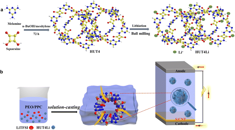 | ||
| Fig. 1 (a) Preparation method of the zwitterion metal covalent organic frame HUT4Li. (b) Preparation of PEO–HUT4Li and PPC–HUT4Li composite polymer electrolyte. | ||
Fig. 2a shows the FTIR spectra of HUT4, CH3COOLi and HUT4Li. The signal peak at 836 cm−1 is attributed to the C![[double bond, length as m-dash]](https://www.rsc.org/images/entities/char_e001.gif) N bond stretching vibration, and the absorption peak at 3471 cm−1 is the stretching vibration of the –NH2 group. The absorption peaks at 1675 and 995 cm−1 correspond to the C
N bond stretching vibration, and the absorption peak at 3471 cm−1 is the stretching vibration of the –NH2 group. The absorption peaks at 1675 and 995 cm−1 correspond to the C![[double bond, length as m-dash]](https://www.rsc.org/images/entities/char_e001.gif) O bond stretching vibration and C–O bond stretching vibration, respectively. It can be observed that the peak strength of the C–O bond is significantly enhanced and the peak deformation of the C
O bond stretching vibration and C–O bond stretching vibration, respectively. It can be observed that the peak strength of the C–O bond is significantly enhanced and the peak deformation of the C![[double bond, length as m-dash]](https://www.rsc.org/images/entities/char_e001.gif) O bond is wide after chemical lithium of HUT4, which proves the successful coordination of Li with the O atom of HUT4. The XRD spectrum is shown in Fig. 2b. The HUT4Li material retains the characteristic peak of HUT4 at 6.55°, which indicates that the incorporation of lithium metal ions preserves the covalent frame structure of HUT4. The charge distribution of HUT4 and HUT4Li is shown in Fig. 2c and d. The positive and negative charges on the surface of HUT4 will reach an even distribution. The polar oxygen of squaric acid with negative potential can combine well with Li+ with positive potential.
O bond is wide after chemical lithium of HUT4, which proves the successful coordination of Li with the O atom of HUT4. The XRD spectrum is shown in Fig. 2b. The HUT4Li material retains the characteristic peak of HUT4 at 6.55°, which indicates that the incorporation of lithium metal ions preserves the covalent frame structure of HUT4. The charge distribution of HUT4 and HUT4Li is shown in Fig. 2c and d. The positive and negative charges on the surface of HUT4 will reach an even distribution. The polar oxygen of squaric acid with negative potential can combine well with Li+ with positive potential.
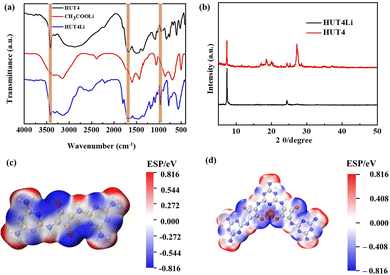 | ||
| Fig. 2 (a) FT-IR spectra of HUT4, CH3COOLi and HUT4Li. (b) XRD spectra of HUT4 and HUT4Li. The charge distribution on the surface of (c) HUT4 and (d) HUT4Li materials. | ||
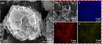
The morphology of HUT4Li was characterized by SEM (Fig. 3a), and it can be observed that the surface is a honeycomb structure composed of multiple layers of nanosheets. As shown in Fig. 3b, the three elements C, N and O are evenly distributed in HUT4Li.
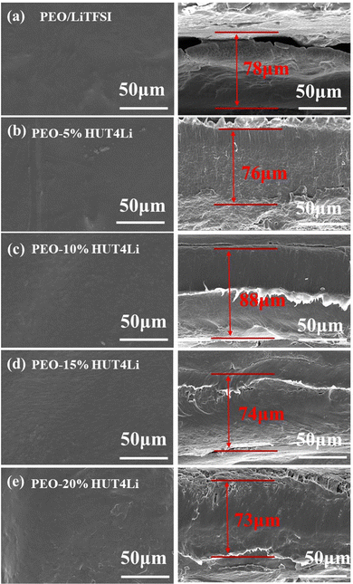
Five kinds of polymer electrolyte membranes with different proportions were prepared by the solution pouring method, and their surface and cross-section morphologies were observed by SEM. The compatibility of membranes and PEO will directly affect the mechanical and electrical properties of electrolytes. It can be observed that the surface morphologies of the other electrolytes are relatively smooth, but the surface of the PEO–20%HUT4Li electrolyte has obvious cracks caused by ion agglomeration (Fig. 4a–e). The compatibility between HUT4Li and PEO in the PEO–10%HUT4Li electrolyte and the PEO–15%HUT4Li electrolyte is good as shown in the morphology. The thickness of both PEO–HUT4Li and PEO/LiTFSI electrolyte membranes is in the range of 70–90 μm, which meets the conditions for assembling practical batteries.39 Therefore, electrolyte membranes with the thickness of this range are used in subsequent experiments.
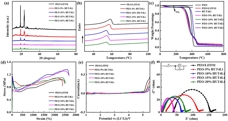
Five electrolyte membranes were tested by XRD to determine the PEO phase transition. Pure PEO has two crystal faces, called the (120) and (112) crystal faces, which correspond to two distinct peaks near 19° and 23°.40Fig. 5a shows that the incorporation of LiTFSI and HUT4Li will reduce the intensity of PEO characteristic peaks and lead to changes in PEO crystallinity. In order to further analyze the change of PEO crystallinity, DSC tests were conducted on five electrolytes, as shown in Fig. 5b, and the melting temperature and crystallinity data are collected in Table S1 (ESI†). The appearance of the endothermic peak represents the melting of the polymer electrolyte. The melting temperature and crystallinity of the PEO10%HUT4Li electrolyte are the lowest, which are 50.67 °C and 37.91%, respectively. The decrease of crystallinity plays a role in promoting the migration of lithium ions.
One of the keys for the safety performance of the battery is the excellent thermal stability of the electrolyte. It can be seen from Fig. 5c that the 3% weight loss corresponds to the dehydration process of the polymer electrolyte in the air, and the thermal decomposition temperatures of PEO and HUT4Li are 352 °C and 387 °C, respectively. Although the thermal decomposition temperature of the electrolyte doped with metal lithium ions is slightly lower (close to 300 °C), it still meets the requirements of battery assembly and use. The mechanical integrity of solid electrolytes under an external force will affect the stability between them and the lithium anode. Therefore, we have explored the mechanical strength of electrolytes through the tensile test (Fig. 5d), and the stress and strain data are summarized in Table S2 (ESI†). The tensile modulus of the PEO–10%HUT4 electrolyte can reach 1.37 MPa. The strong interaction between HUT4Li and PEO will improve the elastic modulus of the electrolyte, thus effectively improving the mechanical properties of the material.
The electrochemical window of the electrolyte was measured by linear sweep voltammetry (LSV). Fig. 5e shows the LSV curves of five electrolytes. The electrolytes doped with metal lithium ions have excellent electrochemical stability for lithium. Previous studies have shown that the wider electrochemical stability window is caused by the strong interaction between small molecules and the capture between a large number of micropores.41 The oxidation electrochemical window of four proportions of solid polymer electrolytes prepared in this work is larger than that of traditional organic electrolytes (3.8 V), which can be matched with the cathode material of high energy density batteries. During the battery operation, lithium dendrite will penetrate the diaphragm and cause a short circuit, so the stability of the battery interface plays a key role in the battery life. The electrolyte membrane is sandwiched between two lithium plate electrodes and assembled into the symmetrical battery to test the impedance of the interface resistance, as shown in Fig. 5f. R2 is related to the interface impedance between the lithium metal and the polymer electrolyte.42–44 The interface resistances of PEO–10%HUT4Li, PEO–15%HUT4Li, and PEO–20%HUT4Li electrolytes are 61.4 Ω, 40.6 Ω and 72.6 Ω, respectively. The maximum interface resistance of PEO–20%HUT4L is due to the non-uniform distribution of electrolytes caused by too much HUT4Li doping. The increase of the lipophilic HUT4Li content at the interface is the reason for the lowest interface resistance of PEO–15%HUT4Li.
The dissociation transfer of Li+ between PEO segments in the amorphous region is further evaluated by the lithium ion migration number (tLi+). tLi+ was calculated by formula 3 according to the chronopotentigrams and EIS curves of the symmetrical battery with five electrolytes at 60 °C (Fig. 6a–d and Fig. S1, ESI†), and the data are collected in Table 1. It can be concluded that HUT4Li as fillers are conducive to improving the transport of Li+. Moreover, the tLi+ values of the PEO–10%HUT4Li electrolyte and the PEO–15%HUT4Li electrolyte were 0.68 and 0.65, respectively. The uniformly dispersed Li+ in the HUT4Li framework make it possess Lewis acid, so the framework can be complexed with oxygen atoms (Lewis base) on PEO,45,46 which is conducive to the transport of Li+. Meanwhile, the tLi+ value of the PEO20%–HUT4Li electrolyte is decreased to 0.51, which may be the poor compatibility between HUT4Li and PEO due to high doping contents, resulting in ion aggregation and reduced Li+ transport.
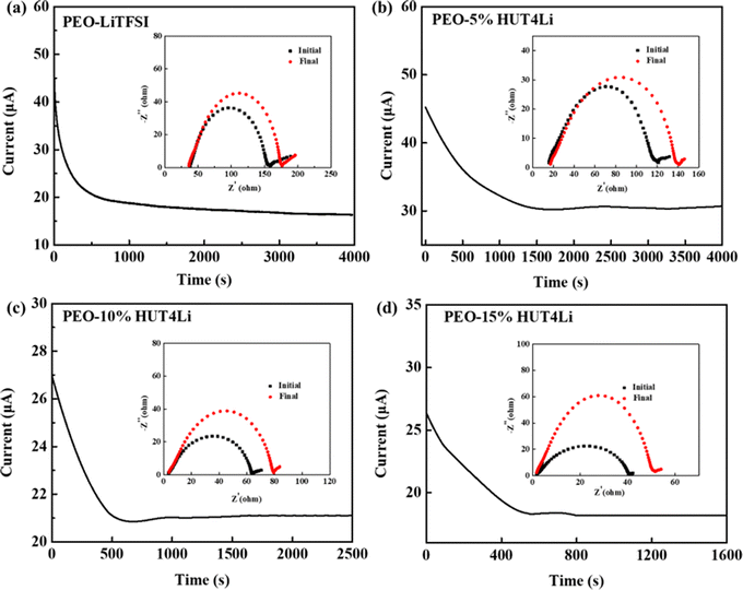 | ||
| Fig. 6 Chronoamperometric curves and EIS spectra of (a) PEO/LiTFSI, (b) PEO–5%HUT4Li, (c) PEO–10%HUT4Li, and (d) PEO–15%HUT4Li. | ||
| Polymer electrolyte | I 0/mA | I S/mA | R 0/Ω | R S/Ω | ΔV/mV | t Li+ |
|---|---|---|---|---|---|---|
| PEO–LiTFSI | 0.042 | 0.015 | 119.02 | 139.65 | 10 | 0.22 |
| PEO–5%HUT4Li | 0.045 | 0.030 | 105.73 | 111.39 | 10 | 0.39 |
| PEO–10%HUT4Li | 0.027 | 0.019 | 60.71 | 76.43 | 10 | 0.68 |
| PEO–15%HUT4Li | 0.025 | 0.017 | 39.37 | 50.18 | 10 | 0.65 |
| PEO–20%HUT4Li | 0.047 | 0.028 | 71.49 | 100.23 | 10 | 0.51 |
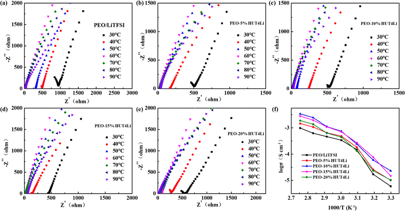
The EIS diagrams of five solid electrolytes at different temperatures are shown in Fig. 7a–e, and the calculated ionic conductivity is collected in Table S3 (ESI†) according to formula 2. It can be concluded from Fig. 7f that the ionic conductivity of the electrolyte can be improved by increasing the temperature. The PEO–10%HUT4Li and PEO–15%HUT4Li electrolytes show considerable conductivity at all temperatures, and the ionic conductivities of the two electrolytes were 3.4 × 10⁻³ S cm−1 and 2.7 × 10⁻³ S cm−1 at 90 °C, respectively. Compared with the PEO–10%HUT4 electrolyte without Li+ in our previous work (5.3 × 10⁻⁴ S cm−1), the ionic conductivity of PEO–10%HUT4Li increases significantly.47 This may be because the uniformly dispersed Li+ in the framework make the surface of HUT4Li possess the Lewis acid. When it is complexed with PEO as a filler, it can increase the amorphous phase area of PEO, thus improving the ionic conductivity of the solid electrolyte. However, when the poor compatibility of HUT4Li and PEO results in phase separation, aggregation and uneven distribution, the ionic conductivity will be reduced.
Characterization structure and electrochemical performance of the PPC–x%HUT4Li (x = 5,10,15,20) electrolyte membrane
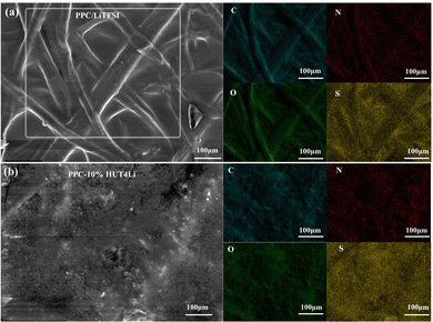
As shown in Fig. S2 (ESI†), the surface morphology of five PPC–x%HUT4Li electrolyte membranes was tested by SEM. Tp is a fibrous porous structure with irregular pores, which also supports the polymer substrate (Fig. S2a, ESI†). After introducing PPC and LiTFSI into the Tp structure, a relatively smooth electrolyte membrane with a tight connection will be obtained, but we can still observe the fiber structure of Tp (Fig. S2b, ESI†). In Fig. S2c (ESI†), when 5%HUT4Li is added into the PPC substrate as a filler, there are obvious pores on the surface of the electrolyte membrane, which is caused by the incomplete compatibility of the filler and Tp. The surface of the PPC10%HUT4Li electrolyte film is uniform, which can increase the overall safety of the battery. In addition, the fiber structure of Tp is no longer obviously observed. It can also prove the perfect compatibility of HUT4Li, PPC and Tp (Fig. S2d, ESI†). If the content of HUT4Li continues to increase, pores and aggregation will appear on the surface of the electrolyte membrane, as shown in Fig. S2e and f (ESI†). The uniformity and compactness of the electrolyte membrane directly affect the mechanical and electrochemical properties of the membrane. Therefore, in the subsequent experiments, we adopt the PPC-10%HUT4Li electrolyte membrane. EDS is used to study the dispersion of C, N, O and S in the electrolyte membrane. In Fig. 8, each element is evenly distributed in the two electrolytes. It can reflect that the HUT4Li filler and LiTFSI have good compatibility in the PPC matrix, and can also indicate the perfect and successful preparation of polymer electrolyte membranes.DSC is used to characterize the crystallinity of PPC, as shown in Fig. S3a (ESI†). The endothermic peaks of PPC/LiTFSI and PPC-10%HUT4Li polymer electrolytes are particularly weak (almost no melting transition), indicating that PPC has been in the amorphous state. The crystal structures of PPC/LiTFSI and PPC-10%HUT4Li polymer electrolytes at different temperatures were analyzed by XRD, as shown in Fig. S3b (ESI†). The PPC-10%HUT4Li electrolyte showed a wider peak near 23°, indicating that the PPC was in the more amorphous state. In addition, the phase composition of the two polymer electrolytes at 30°, 50° and 70° remains unchanged and both are amorphous. This result corresponds to the DSC analysis. Therefore, it is reasonable to think that the amphoteric stable structure of the HUT4Li filler has good compatibility with PPC, and more amorphous regions are added to provide more favorable conditions for Li+ transport. The excellent thermal stability of the electrolyte can significantly improve the safety performance of the battery and reduce the potential risk of the short circuit during the use of the battery. Therefore, the thermal stability of the polymer electrolyte was further characterized by the TG test of two electrolytes (Fig. S3c, ESI†). The curves of PPC/LiTFSI and PPC-10%HUT4Li polymer electrolytes are almost the same, which shows that the addition of the HUT4Li filler does not affect the crystallinity of solid polymer electrolytes too much. Fig. S3d (ESI†) shows the tensile curve of the polymer electrolyte, and the specific number is shown in Table S4 (ESI†). The addition of the 10%HUT4Li filler can enhance the mechanical properties of the electrolyte, and the PPC-10%HUT4Li electrolyte has considerable tensile strength and elongation at break. It may be that the flexible structure of HUT4Li increases the flexibility of the PPC chain. In addition, the stability of the interface between the polymer electrolyte and the lithium metal is also one of the important references to realize the cycle stability of the battery.
Ion conductivity is an important parameter to evaluate the performance of the electrolyte. In the lithium–lithium symmetrical battery system, we evaluated the lithium ion migration number of PPC/LiTFSI and PPC-10%HUT4Li polymer electrolytes (Fig. 9a and b), and the data are summarized in Table 2. The lithium ion migration number of the PPC/LiTFSI electrolyte is 0.28, while that of the PPC-10%HUT4Li electrolyte is 0.54. The significant increase of the lithium ion migration number is due to the fact that HUT4Li as a filler can increase the amorphous phase of the PPC chain segment, thus increasing the lithium ion transport channel. In addition, the uniformly dispersed metal lithium ions in the amphoteric covalent organic framework structure will make the filler surface have more active sites, which will promote the better dissociation of lithium ions from lithium salts, thus providing more favorable conditions for the transmission of lithium ions42 We assembled an asymmetric cell to measure the LSV curve. As shown in Fig. 9c, the electrochemical stability of PPC/LiTFSI and PPC-10%HUT4Li polymer electrolytes can reach 4.42 V and 4.63 V, respectively. The addition of the HUT4Li filler has a positive impact on the electrochemical stability window. Therefore, the PPC-10%HUT4Li polymer electrolyte can meet the requirements of practical applications of lithium sulfur batteries. In addition, the stability of the interface between the polymer electrolyte and the lithium metal is also one of the important references to realize the cycle stability of the battery. Fig. 9d shows the interface impedance between the polymer electrolyte and the lithium metal. The interface impedance between PPC-10%HUT4Li and PPC/LiTFSI electrolytes and the lithium metal is 83.4 Ω and 96.4 Ω, respectively. The semicircle is related to the interface impedance of the lithium metal and the polymer electrolyte, and the straight line is related to the Warburg impedance in the diffusion process. Both electrolytes show stability with the lithium metal.
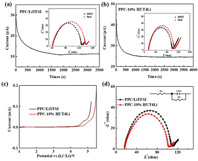 | ||
| Fig. 9 Chronoamperometric curves and EIS spectra of (a) PPC/LiTFSI and (b) PPC-10%HUT4Li. (c) LSV curves of electrolytes. (d) Interface EIS spectrum of electrolytes. | ||
| Polymer electrolyte | I 0/mA | I S/mA | R 0/Ω | R S/Ω | ΔV/mV | t Li+ |
|---|---|---|---|---|---|---|
| PPC–LiTFSI | 0.031 | 0.011 | 84.75 | 91.41 | 10 | 0.28 |
| PPC-10%HUT4Li | 0.044 | 0.024 | 82.62 | 96.48 | 10 | 0.54 |
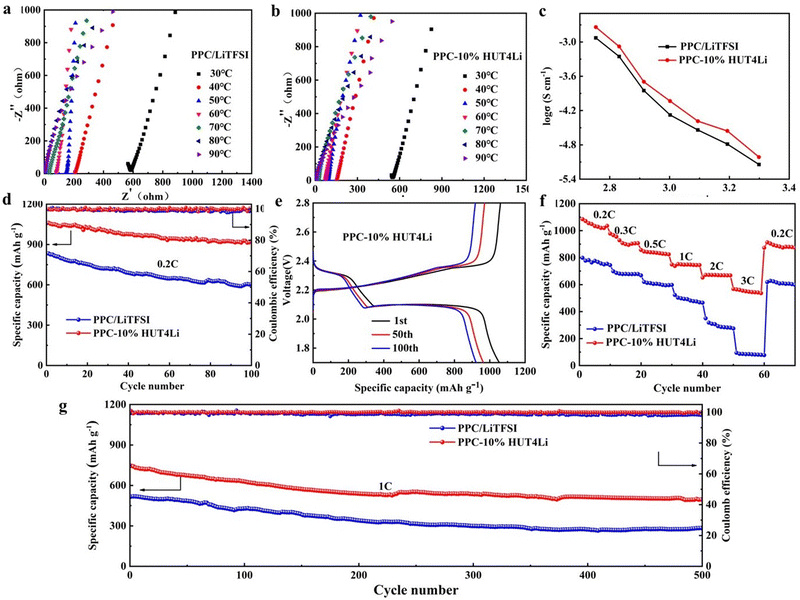
Fig. 10a–c shows the curve of the ionic conductivity of PPC/LiTFSI and PPC-10%HUT4Li polymer electrolytes with temperature, and the data are summarized in Table S5 (ESI†). The ionic conductivities of PPC-10%HUT4Li and PPC/LiTFSI polymer electrolytes at 90 °C are 1.9 × 10⁻³ S cm−1 and 1.2 × 10⁻³ S cm−1, respectively. We can infer that the filling of HUT4Li can increase more amorphous phases in PPC, reduce the transport activation energy of ions, and thus improve the ionic conductivity of the PPC-10%HUT4Li electrolyte.
In order to observe the practical application of electrolytes in batteries, we assembled the two polymer electrolytes into Li–S batteries to test their electrochemical performance. The cathode of the assembled battery has a sulfur content of 75% and sulfur load of 1.29 mg cm−2 (Fig. S4, ESI†). Fig. 10d shows the constant-current charge–discharge test. The initial specific capacity of the quasi-solid Li–S battery assembled with the PPC-10%HUT4Li polymer electrolyte is 1046 mA h g−1, and the capacity retention rate can reach 88.9% after 100 cycles at 0.2C. The initial specific capacity of the quasi-solid Li–S battery assembled with the PPC/LiTFSI electrolyte is 833 mA h g−1, and the capacity retention rate is only 72.5%. Fig. 10e shows the charge–discharge curve of the Li–S battery based on two polymer electrolytes at 0.2C. With the increase of the number of cycles, the polarization of the battery does not increase significantly, and the decay rate also tends to be stable, which can further prove the superiority of the PPC10%HUT4Li polymer electrolyte. Therefore, it can be seen that the PPC-10%HUT4Li polymer electrolyte shows higher discharge specific capacity and better capacity retention.
The electrochemical performance of the Li–S battery at different rates is shown in Fig. 10f. The specific capacity of the quasi-solid Li–S battery with PPC-10%HUT4Li was stable at 1078 mA h g−1 at 0.2C. With the current density increasing to 0.3C, 0.5C, 1C, 2C, and 3C, the specific capacities were 927 mA h g−1, 837 mA h g−1, 744 mA h g−1, 675 mA h g−1, and 548 mA h g−1, respectively. When the current density returns to 0.2C, the capacity is still considerable. Compared with the PPC/LiTFSI polymer electrolyte, the quasi-solid Li–S battery assembled with PPC10%HUT4Li has better magnification performance. The long cycle stability of two Li–S batteries based on electrolyte materials is shown in Fig. 10g. The initial specific capacity of the quasi-solid Li–S battery assembled by PPC-10%HUT4Li was stable at 758 mA h g−1, and the specific capacity was stable at about 489 mA h g−1 after 500 cycles at 1C. The initial specific capacity of the quasi-solid Li–S battery assembled by the PPC/LiTFSI polymer electrolyte was stable at 514 mA h g−1. After 500 cycles, the specific capacity decreased to about 284 mA h g−1. The reason for this phenomenon is that PPC10%HUT4Li has a higher lithium ion migration number and higher ionic conductivity, which makes it easier for Li+ to migrate between the cathode and the anode. Moreover, the first circle Coulomb efficiency of PPC-10%HUT4Li is better than that of PPC–LiTFSI, which is 99.5% and 99.29%, respectively (Fig. 10d and g).
Conclusions
In summary, the metal covalent organic framework (HUT4Li) was prepared by successfully mixing Li+ with HUT4 by mechanical ball milling. HUT4Li was added into PEO and PPC as the filler to prepare PEO–HUT4Li and PPC–HUT4Li composite polymer electrolytes by solution pouring. The uniformly dispersed Li+ in the frame structure will make the HUT4Li surface have specific Lewis acid and active sites, which not only create a favorable environment for the transport of lithium ions, but also improve the ionic conductivity. The strong interaction between HUT4Li and PEO and PPC will improve the elastic modulus of the polymer electrolyte, thus effectively improving the mechanical properties of the material, and also increasing the interface stability between the electrolyte and the lithium anode. The introduction of Li+ into the zwitterionic metal covalent organic frameworks through mechanical ball milling provides a new method and direction for the preparation of fillers for composite polymer electrolytes.Author contributions
Conceptualization: H. L.; methodology: H. L.; formal analysis: H. L. and L. J.; investigation: H. L. and J. L.; data curation: H. G.; writing – original draft preparation: H. L.; writing – review and editing: H. L. and X. Z.; supervision: T. L. and X. Z.; funding acquisition: T. L. All authors have read and agreed to the published version of the manuscript.Conflicts of interest
There are no conflicts to declare.Acknowledgements
This work was supported by the Key Project of Tianjin Science and Technology Support Programs of China (Grant No. 20YFZCSY00310) and the Science Foundation of Tianjin Health and Family Planning Commission of China (Grant No. T JW J2022MS021).Notes and references
- S. Liu, L. Kang and S. C. Jun, Adv. Mater., 2021, 33, 2004689 CrossRef CAS PubMed.
- S. Liu, L. Kang, J. Henzie, J. Zhang, J. Ha, M. A. Amin, M. S. Hossain, S. C. Jun and Y. Yamauchi, ACS Nano, 2021, 15, 18931–18973 CrossRef CAS PubMed.
- S. Liu, D. Ni, H. F. Li, K. N. Hui, C. Y. Ouyang and S. C. Jun, J. Mater. Chem. A, 2018, 6, 10674–10685 RSC.
- M. M. Zhang, P. Pan, Z. L. Cheng, J. T. Mao, L. Y. Jiang, C. K. Ni, S. K. Park, K. Y. Deng, Y. Hu and K. K. Fu, Nano Lett., 2021, 21, 7070–7078 CrossRef CAS PubMed.
- C. Yan, Y. Zhou, H. Cheng, R. Orenstein, P. Zhu, O. Yildiz, J. Jur and N. Q. Wu, Energy Storage Mater., 2022, 44, 136–144 CrossRef.
- Y. Zhang, W. Lu, D. Manaig, D. J. Freschi, Y. L. Liu, H. M. Xie and J. Liu, J. Colloid Interface Sci., 2022, 605, 547–555 CrossRef CAS PubMed.
- L. T. Wang, Y. L. Zhong, Z. R. Wen, C. W. Li, J. X. Zhao, M. Z. Ge, P. F. Zhou, Y. Y. Zhang, Y. X. Tang and G. Hong, Sci. China Mater., 2022, 65, 2179–2188 CrossRef CAS.
- Y. T. Zhu, J. C. Gonzalez-Rosillo, M. Balaish, H. Z. D. Hood, K. J. Kim and J. Rupp, Nat. Rev. Mater, 2021, 6, 313–331 CrossRef CAS.
- H. Wan, J. P. Mwizerwa, X. Qi, X. Xu, H. Li, Q. Zhang, L. Cai, Y. S. Hu and X. Yao, ACS Appl. Mater., 2018, 10, 12300–12304 CrossRef CAS PubMed.
- C. W. Wang, H. Xie, W. W. Ping, J. Q. Dai, G. L. Feng, Y. G. Yao, S. M. He, J. Weaver, H. Wang and K. Gaskell, Energy Storage Mater., 2019, 17, 234–241 CrossRef.
- C. Shen, Y. B. Huang, J. R. Yang, M. J. Chen and Z. P. Liu, Energy Storage Mater., 2021, 39, 271–277 CrossRef.
- B. P. Dubey, A. Vinodhkumar, A. Sahoo, V. Thangadurai and Y. Sharma, Acs Appl. Energy Mater., 2021, 4, 5475–5485 CrossRef CAS.
- Q. Zhang, D. X. Cao, Y. Ma, A. Natan, P. Aurora and H. L. Zhu, Adv. Mater., 2019, 31, 1901131 CrossRef CAS PubMed.
- C. Yu, S. Ganapathy, E. R. H. Van Eck, H. Wang, S. Basak, Z. L. Li and M. Wagemaker, Nat. Commun., 2017, 8, 1086 CrossRef PubMed.
- K. Homma, M. Yonemura, T. Kobayashi, M. Nagao, M. Hirayama and R. Kanno, Solid State Ionics, 2011, 182, 53–58 CrossRef CAS.
- Q. Zhao, S. Stalin, C. Z. Zhao and L. A. Archer, Nat. Rev. Mater., 2020, 5, 229–252 CrossRef CAS.
- D. Golodnitsky, E. Strauss, E. Peled and S. J. Greenbaum, Electrochem. Soc., 2015, 162, A2551–A2566 CrossRef CAS.
- C. M. Costa, M. M. Silva and S. Lanceros-Mendez, RSC Adv., 2013, 3, 11404–11417 RSC.
- J. J. Zhang, J. F. Yang, T. T. Dong, M. Zhang, J. C. Chai, S. M. Dong, T. Y. Wu, X. H. Zhou and G. L. Cui, Small, 2018, 14, 1800821 CrossRef PubMed.
- A. Arya and A. L. Sharma, Ionics, 2017, 23, 497–540 CrossRef CAS.
- X. G. Liu, H. Wen, B. B. Guo, C. Z. Lv, W. M. Shi, W. B. Kang, J. H. Zhang, R. X. Yuan and C. H. Zhang, Adv. Energy Mater., 2021, 11, 2100310 CrossRef CAS.
- Z. W. Cheng, T. Liu, B. Zhao, F. Shen, H. Y. Jin and X. G. Han, Energy Storage Mater., 2021, 34, 388–416 CrossRef.
- L. Zeng, L. Jia, X. G. Liu and C. H. Zhang, Polymers, 2020, 12, 2937 CrossRef CAS PubMed.
- Z. G. Xue, D. He and X. L. Xie, J. Mater. Chem. A, 2015, 3, 19218–19253 RSC.
- L. S. Li, Y. F. Deng and G. H. Chen, J. Energy Chem., 2020, 50, 154–177 CrossRef.
- L. Zhu, P. H. Zhu, S. S. Yao, X. Q. Tu and F. Y. Tu, Int. J. Energy Res., 2019, 43, 4854–4866 CrossRef CAS.
- X. J. Zhu, Z. Y. Wen, Z. H. Gu and Z. X. Lin, J. Power Sources, 2005, 139, 269–273 CrossRef CAS.
- L. Porcarelli, C. Gerbaldi, F. Bella and J. R. Nair, Sci. Rep., 2016, 6, 19892 CrossRef CAS PubMed.
- R. Khurana, J. L. Schaefer, L. A. Archer and G. W. Coates, J. Am. Chem. Soc., 2014, 136, 7395–7402 CrossRef CAS PubMed.
- W. Zaman, N. Hortance, M. B. Dixit, V. De Andrade and K. B. Hatzell, J. Mater. Chem. A, 2019, 7, 23914–23921 RSC.
- F. Makhlooghiazad, L. A. O'Dell, L. Porcarelli, C. Forsyth, N. Quazi, M. Asadi, O. Hutt, D. Mecerreyes, M. Forsyth and J. M. Pringle, Nat. Mater., 2022, 21, 228–236 CrossRef CAS PubMed.
- S. Yan, Y. Lu, F. Liu, Y. Xia, Q. Li and K. Liu, CCS Chem., 2023, 5, 1612–1622 CrossRef CAS.
- J. Q. Guo, Y. P. Chen, Y. B. Xiao, C. P. Xi, G. Xu and B. R. Li, Chem. Eng. J., 2021, 422, 130526 CrossRef CAS.
- H. S. Xu, Y. Luo, X. Li, P. Z. See, Z. X. Chen, T. Q. Ma, L. Liang, K. Leng, I. Abdelwahab, L. Wang, R. L. Li, X. Y. Shi, Y. Zhou, X. F. Lu, X. X. Zhao, C. B. Liu, J. L. Sun and K. P. Loh, Nat. Commun., 2020, 11, 1434 CrossRef CAS PubMed.
- J. Q. Dong, X. Han, Y. Liu, H. Y. Li and Y. Cui, Angew. Chem., Int. Ed., 2020, 59, 13722–13733 CrossRef CAS PubMed.
- X. Li, Q. Hou, W. Huang, H. S. Xu, X. W. Wang, W. Yu, R. L. Li, K. Zhang, L. Wang and Z. X. Chen, ACS Energy Lett., 2020, 5, 3498–3506 CrossRef CAS.
- C. Guo, J. Zhou, Y. Chen, H. Zhuang, J. Li, J. Huang, Y. Zhang, Y. Chen, S.-L. Li and Y.-Q. Lan, Angew. Chem., Int. Ed., 2023, 62, e202300125 CrossRef CAS PubMed.
- Q. Zhang, J. Luan, L. Fu, S. Wu, Y. Tang, X. Ji and H. Wang, Angew. Chem., Int. Ed., 2019, 58, 15841–15847 CrossRef CAS PubMed.
- Z. Zhang, Y. Huang, H. Gao, C. Li, J. Huang and P. J. Liu, Membr. Sci, 2021, 621, 118940 CrossRef CAS.
- Y. Lin, X. M. Wang, J. Liu and J. D. Miller, Nano Energy, 2017, 31, 478–485 CrossRef CAS.
- Z. A. Ghazi, L. Y. Zhu, H. Wang, A. Naeem, A. M. Khattak, B. Khan, N. A. Liang, Z. X. Wei, L. S. Li and Z. Y. Tang, Adv. Energy Mater., 2016, 6, 1601250 CrossRef.
- S. Liu, L. Kang, J. Zhang, E. Jung, S. Lee and S. C. Jun, Energy Storage Mater., 2020, 32, 167–177 CrossRef.
- S. Liu, L. Kang, J. Zhang and S. C. Jun, ACS Energy Lett., 2021, 6, 4127–4154 CrossRef CAS.
- G. Yang, X. Bai, Y. Zhang, Z. Guo, C. Zhao, L. Fan and N. Zhang, Adv. Funct. Mater., 2023, 33, 2211387 CrossRef CAS.
- Z. Hu, Q. N. Liu, S. L. Chou and S. X. Dou, Adv. Mater., 2017, 29, 1700606 CrossRef PubMed.
- H. Chen, D. Adekoya, L. Hencz, J. Ma, S. Chen, C. Yan, H. J. Zhao, G. L. Cui and S. Q. Zhang, Adv. Energy Mater., 2020, 10, 2000049 CrossRef CAS.
- Y. Wang, S. Geng, G. Yan, X. Liu, X. Zhang, Y. Feng, J. Shi and X. A. Qu, ACS Appl. Energy Mater., 2022, 5, 2495–2504 CrossRef CAS.
Footnote |
| † Electronic supplementary information (ESI) available. See DOI: https://doi.org/10.1039/d3ma00774j |
| This journal is © The Royal Society of Chemistry 2023 |

