DOI:
10.1039/D3MA00654A
(Paper)
Mater. Adv., 2023,
4, 5808-5816
Spectroscopically enhanced far-red phosphor Li2Mg3TiO6:Cr3+ and its application prospects to the cold resistance of rice†
Received
2nd September 2023
, Accepted 16th October 2023
First published on 19th October 2023
Abstract
Chemical unit co-substitution is a very effective strategy to improve the properties of phosphors. Due to the mismatch of the radii between substituted ions, unexpected properties are usually produced. Such properties are of profound significance to expand the research field. In this study, Mg2+–Ti4+ in Li2Mg3TiO6:Cr3+ was replaced by Al3+–Al3+ and Ga3+–Ga3+, while the charge balance was maintained. Ion substitution changed the crystal field environment of activator ions, which increased the luminescence intensity by 180% and 184% respectively, accompanied by a slight decrease in thermal stability. In addition, the quantum efficiency was increased from 35.1% to 73.1%. The electroluminescence spectrum of the encapsulated pc-LED was examined, and the overlap with the absorption profile of the phytochrome Pfr was 61%. In order to verify the application prospects of far-red phosphor a 15 day rice growth experiment was set up to detect surface traits, soluble sugars, soluble proteins, and the expression of OsphyA and OsCBF3 genes. It was demonstrated that rice had significant resistance enhancement under far-red light irradiation.
1. Introduction
Since human society entered the 21st century, the process of social industrialization has been accelerating, leading to a deterioration of the environment and a decrease in agricultural production.1–3 Crops grown outdoors are highly susceptible to extreme weather, which can make it difficult to get high-quality food. Plant factories, as efficient agricultural facilities, can handle these issues well.4,5 The most important component in a plant factory is the light source. Light sources are indispensable for plant growth and affect the whole period of the plant's growth. Light acts on plants through photoallergens.6 Typically, plants absorb both blue and red light, with the red light being divided into red light and far red light. This corresponds to the response of different biological pigments in plants to light: chlorophyll A absorbs red light in the 420 nm to 663 nm range, chlorophyll B absorbs blue light in the 460 nm to 645 nm range, phytochrome Pr absorbs red light with a peak at 660 nm and phytochrome Pfr absorbs far-red light with a peak at 730 nm.7,8 In the field of plant factories, the light source used for plant lighting is usually pc-LEDs. This complementary light method has the advantage of being small and energy-efficient and can accurately correspond to the spectral absorption of the plant. Zhong and Zhou et al. investigated the method of the blue LED chip and red phosphor for plant lighting with remarkable results, which marks the broad application prospects of pc-LEDs in the plant field.9 In addition to blue and red light, far-red light can affect plant growth and development. Generally, far-red light has two effects on plants: shading and flowering induction.10 When exposed to far-red light, the plants appear to be blocked by other leaves, which causes them to grow taller for more sunlight. From this, the plant height can be tuned by adjusting the red/far-red light ratio. Liu et al.11 reported a novel phosphor Ga2O3:Cr3+ that perfectly matches the absorption of phytochrome Pfr, and two kinds of plants “Aglaonema” and “P. amboinicus” were selected for the application study. Gai and Xia et al. also prepared the Mg2SnO4:Cr3+ phosphor and the experiment on tomato quality was carried out.12
Mn4+ is considered the most typical activator of phosphors used in plant lighting, and can emit red or far-red light, for example: LaAlO3:Mn4+ (centered at 726 nm),13 SrLaAlO4:Mn4+ (centered at 730 nm),14 and CaYAlO4:Mn4+ (centered at 713 nm).15 With the development of science and technology, it was gradually discovered that the non-rare earth element Cr3+ also has excellent properties. Specifically, compared to Mn4+, the luminescence of Cr3+ is more susceptible to the crystal field strength (CFS), under which Cr3+ can produce a tunable spectrum from the far-red to the near-infrared region. The excitation range is from 200 to 650 nm. Most studies have shown that the boundary Dq/B value between strong and weak crystal fields is 2.3. In a strong crystal field, the electron makes a 2E → 4A2 transition, emitting far-red light. When in the weak crystal field, 4T2 → 4A2 transitions occur, emitting near infrared light. In the intermediate crystal field, 4T2 → 4A2 transitions and 2E → 4A2 transitions occur and emit near infrared and far-red light.16,17 Due to this property, Cr3+ excited phosphors can be widely used in the field of near-infrared luminescence. For plant illumination, the performance of Cr3+ in far-red illumination is utilized. For example, the emission peak of phosphors, such as Na3AlF6:Cr3+, K3AlF6:Cr3+, Rb2NaAlF6:Cr3+, and KMgF3:Cr3+, is around 730 nm.18–21 However, these phosphors all contain fluoride, and hydrofluoric acid is used in the preparation process, which is extremely unfriendly to agricultural ecology and the social environment. Therefore, the current research focuses on oxide phosphors, which also have excellent luminous properties. Garnet phosphor Gd3Al2Ga3O12:Cr3+ (IQE = 97.3%, EQE = 70.1%)22 has excellent thermal stability. Other garnet-structured phosphors such as Gd2.4Lu0.6Ga4AlO12:Cr3+![[thin space (1/6-em)]](https://www.rsc.org/images/entities/char_2009.gif) 23 and Gd3Sc1.5Al0.5Ga3O12:Cr3+24 also have good photometric properties.
23 and Gd3Sc1.5Al0.5Ga3O12:Cr3+24 also have good photometric properties.
Chemical unit co-substitution can tune the emission spectrum in an efficient way by simultaneously changing the two structural units to adjust the coordination environment of the activator ions. Zhong et al. improved the quantum efficiency of Ca14Ga10Zn6O35:Mn4+ from 38.0% to 50.9% by an unit co-substitution strategy.25 Zhang et al. substituted W6+–Ga3+ and W6+–Al3+ for Ti4+–Sb5+ and increased the luminescence intensity of LaTiSbO6:Mn4+ by 204% and 182%, respectively.26 Li2Mg3TiO6:Cr3+ has perfect octahedral site points, which can provide a coordination environment for Cr3+ ions. In addition, it is exciting to adjust the emission peak shift of this phosphor beyond 200 nm by the concentration of Cr3+27 (from 720 nm to 920 nm).
In this work, the Li2Mg3TiO6:Cr3+ phosphor was successfully prepared. From previous studies, it is known that the phosphor emission peak is affected by the Cr3+–Cr3+ substitution of Mg2+–Ti4+,27 so we have chosen the appropriate Cr3+ concentration for better optimization. By replacing the Mg2+–Ti4+ sites with Al3+–Al3+ and Ga3+–Ga3+ ions, the far-red emission of the material is enhanced with a slight decrease in thermal stability. This is a valid and exciting result. A lot of testing and analysis was done. Finally, LED devices packaged with blue-light chips and the experiment on the improvement of cold resistance of rice by far red light was added. This indicates that the as-prepared phosphor has a wide range of potential applications in the field of plant lighting.
2. Experimental sections
2.1. Sample synthesis
A series of Li2Mg3TiO6:Cr3+ phosphors were prepared via a high temperature solid phase method. Li2CO3 (99.99%), MgO (99.99%), TiO2 (99.99%), and Cr2O3 (99.99%), Al2O3 (99.99%), and Ga2O3 (99.99%) were used as the raw materials, weighed by stoichiometric ratio, transferred to an agate mortar for full reaction for 30 min, and then the mixture was filled into a corundum crucible for firing in two steps: first, it was fired for 4 h in the air atmosphere of the box furnace at 800 °C. After cooling, it was re-ground and then fired for 6 h at 1280 °C. All fired samples are ground into powder for subsequent testing.
2.2. Sample characterization
The X-ray diffraction (XRD) patterns of the powders were obtained by using a diffractometer (Bruker, Germany) with the Cu-Kα radiation and in a test range of 10–80°. The fluorescence spectra (PL and PLE), thermal resistance and quantum yield were detected using a fluorescence spectrophotometer (Edinburgh FLS1000, UK). The UV-vis diffuse reflectance (DR) spectra were obtained using a spectrophotometer (SHIMADZU UV-2600i, Japan). The electroluminescence (EL) spectra and electro-optical conversion efficiency of the LED devices were recorded using a measurement system (ATA-500, Everfine, China).
2.3. PC-LED fabrication
Using a mixture of LMTGO:Cr3+ and epoxy resin, dot coating on the blue light chip was transferred to the oven at 120 °C for 12 hours to fully cure it and conduct subsequent tests.
2.4. Experiment on rice growth variation
2.4.1. Crop growth.
The experiment was conducted in the optical plant laboratory of Hunan Agricultural University, with the rice variety XiangZaoxian24, at a temperature of 25 ± 5 °C and humidity of 50 ± 10%. The planting area was 60 × 120 × 200 (cm).
2.4.2. Planting conditions.
Disinfection with a solution of sodium hypochlorite at a concentration of 5% for 20 minutes was done. The seeds were repeatedly rinsed with tap water and soaked in more than 1 L of water for 24 h. The water was changed every 12 h. The sterilized soaked rice seeds were placed in a 37 °C incubator to germinate for 36 h. Rice with a root length of about half a grain was selected and sown in a seedling tray with a size of 30 × 60 × 10 (cm) and a total of 169 holes, with 4 seeds per hole, using nutrient-free vermiculite as the substrate. The whole nutrient solution was used for cultivation and planting, and the nutrient solution was changed every 3 days. After 15 days of planting, some plants were randomly selected for follow-up testing. The plants were then subjected to white light at a low temperature of 4 °C and 400 ± 10 mmol s−1 light intensity for one day to simulate the phenomenon of spring cold, and then a portion of the sample was stored in an ultra-low temperature refrigerator at −80 °C for subsequent testing.
2.4.3. Rice trait testing.
Plant height and stem base width were measured with tape rulers and vernier calipers respectively. Above-ground and below-ground parts of rice seedlings planted under two light conditions for 15 d were taken separately, rinsed with distilled water, and then the surface water was drained with filter paper and the fresh weight was weighed, after which they were transferred to an oven and dried at 105 °C to a constant weight and weighed as dry weight. 0.2 g fresh sample was weighed and ground well. By setting the speed at 3000 rpm, centrifugation was done for 10 min; 1.0 mL supernatant was taken, and 5 mL of 100 mg L−1 Coomassie bright blue was added, shaken well, and allowed to stand for 2 min. Absorbance was measured with a 595 nm enzyme spectrometer, and the soluble protein content was calculated. The expressions of OsphyA and OsCBF3 genes were analyzed by real-time fluorescence quantitative RT-PCR with a reaction volume of 10 μL, includes cDNA 2 μL, Hieff®qPCR SYBR GreenMasterMix 5 μL, forward primer 0.2 μL, reverse primer 0.2 μL, and ddH2O 2.6 μL.
3. Results and discussion
3.1. Phase identification and crystal structure
Fig. 1a shows the XRD patterns of Li2Mg3TiO6 doped with different Cr3+ concentrations. Due to the absence of JCPDS of Li2Mg3TiO6, Li2Mg3SnO6 (JCPDS 39-0392) with a similar crystal structure was used as the standard card for comparison, and professional software was used for model fitting. As shown in Fig. 1b, it is seen that the crystal structure is fully consistent with Li2Mg3TiO6 when the ratio of Li, Mg and Ti is constrained to 2:3:1 for refinement. Detailed parameters are listed in Tables 1 and 2. It can be observed from the illustration of Fig. 1a that the diffraction peak near 43° gradually moves to a higher angle, which is caused by the gradual increase of Cr3+ concentration. Cr3+ (0.615 Å, CN = 6) and Ti4+ (0.605 Å, CN = 6) have very similar ionic radii, while Mg2+ (0.72 Å, CN = 6) has larger radii. This peak shift proves that Cr3+–Cr3+ replaces Mg2+–Ti4+ in LMTO. Fig. 1c shows that the crystal structure model of the LMTO. Li+, Mg2+ and Ti4+ occupy a common octahedral position point with a ratio of 2:3:1, connecting oxygen atoms at the same bond length. The XRD diffraction patterns obtained after the substitution of Al3+–Al3+ and Ga3+–Ga3+ are archived in Fig. S1 of the ESI,† and the measured diffraction peaks are consistent with the standard cards of Li2Mg3SnO6.
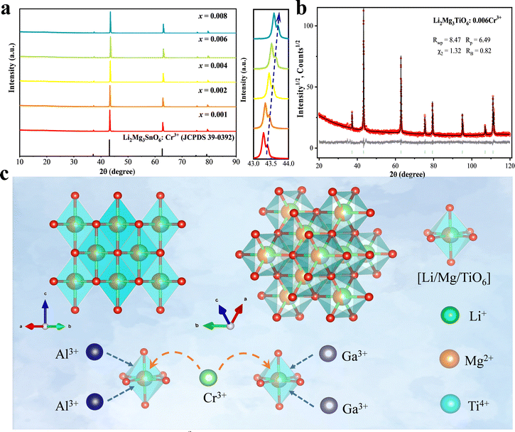 |
| | Fig. 1 (a) XRD spectrum of Li2Mg3TiO6:xCr3+ compared with the Li2Mg3SnO6 standard card; (b) refinement of Li2Mg3TiO6; and (c) crystal structure diagram and chemical unit co-substitution schematic model of Li2Mg3TiO6. | |
Table 1 Main parameters of processing and refinement of the Li2Mg3TiO6 samples
| Compound |
Li2Mg3TiO6 |
| Sp. Gr. |
Fm![[3 with combining macron]](https://www.rsc.org/images/entities/char_0033_0304.gif) m m |
|
a (Å) |
4.17823(3) |
|
V (Å3) |
72.9421(17) |
| 2θ-interval, ° |
20–120 |
|
R
wp, % |
8.47 |
|
R
p, % |
6.49 |
|
χ
2
|
1.32 |
|
R
B, % |
0.82 |
Table 2 Fractional atomic coordinates and isotropic displacement parameters (Å2) of Li2Mg3TiO6
| Atom |
x
|
y
|
z
|
B
iso
|
Occ. |
| Li |
0 |
0 |
0 |
0.6(3) |
1/3 |
| Ti |
0 |
0 |
0 |
0.6(3) |
1/6 |
| Mg |
0 |
0 |
0 |
0.6(3) |
1/2 |
| O |
0.5 |
0.5 |
0.5 |
1.0(3) |
1 |
3.2. Spectroscopic properties
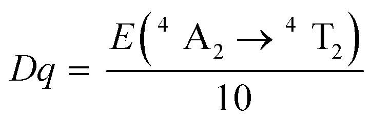
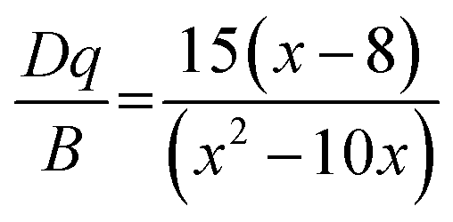
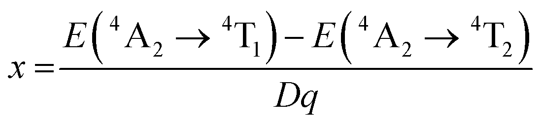
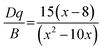
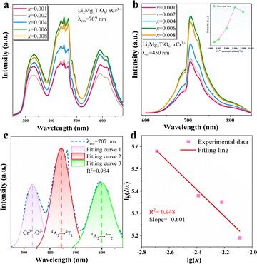
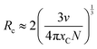
High concentrations of Cr3+ doping will cause the LMTO emission to shift into the NIR region. When the concentration of Cr3+ is limited to less than 1%, the emission peak does not shift and the intensity gradually increases over a concentration range of 0.001–0.009. When the concentration of Cr3+ gradually increases, it is shown in Fig. 2a and b that three excitation bands exist from 250 nm to 600 nm, located at 330 nm, 450 nm and 590 nm respectively. The optimum excitation band ranges from 400 nm to 500 nm. The emission spectra range from 600 nm to 850 nm with a peak at 707 nm. The first excitation peak in the UV region is attributed to the charge transfer band (CTB) of Cr–O, and the second and third peaks are from the spin-allowed 4A2 → 4T1 (4F) and 4A2 → 4T2 (4F) transitions of Cr3+, respectively (Fig. 2c). It is worth noting that Cr3+ emission generally has both an R-line and a broadband, attributed to the 2E → 4A2 and 4T2 → 4A2 transitions of Cr3+, respectively.28 The generation of these two transitions depends on the CFS around Cr3+. In strong crystal field systems, the R-line emission dominates, while in weak crystal field systems, broadband emission dominates; in some phosphors, both R-line and broadband emission transitions are present. The CFS is judged by Dq/B = 2.3 as a cut-off value.29 When Cr3+ occupies the octahedral site, the CFS can be calculated according to the following equation:30,31| | 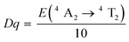 | (1) |
| |  | (2) |
| |  | (3) |
where E(4A2 →4T1) and E(4A2 →4T2) represent the energy difference between 4A2 levels and 4T1 and 4T2 levels, which can be determined by the position of excitation peaks to be 22222 cm−1 and 16949 cm−1. The calculated Dq/B value for LMTO:Cr3+ is 3.57, which represents a strong crystal field and consistent with the previously reported far-red emission of Cr3+ in a strong crystal field.
 |
| | Fig. 2 (a) and (b) Excitation and emission spectra of Li2Mg3TiO6 for different Cr3+ concentrations, (c) Gaussian fitted Li2Mg3TiO6:0.006 Cr3+ excitation profile, and (d) relationship between log(x) and log(I/x). | |
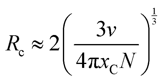
The illustration of Fig. 2b shows the dotted line plot of Cr3+ concentration addition. When x = 0.006, the luminous intensity is the strongest, and then the luminous intensity decreases due to concentration quenching; the critical distance (Rc) can be used to explain the mechanism of this phenomenon:32,33
| |  | (4) |
where
N,
XC and
V represent the possible sites occupied by Cr
3+, the activator ion concentration and cell volume respectively. The calculated
Rc is 28.53, the value is greater than 5 Å, and so the mechanism of energy transfer is a multipole–multipole interaction. The specific interactions can be calculated from the following equations:
33,34| |  | (5) |
where
x represents the concentration of Cr
3+ ions and
I represents the luminous intensity of Cr
3+ ions. Under the same test conditions, both
k and
β are constants. The slope shown in
Fig. 2d is −0.6, so the value of
x is 1.8, which is close to 3. Therefore, exchange interactions are the mechanism of concentration quenching in LMTO:Cr
3+.
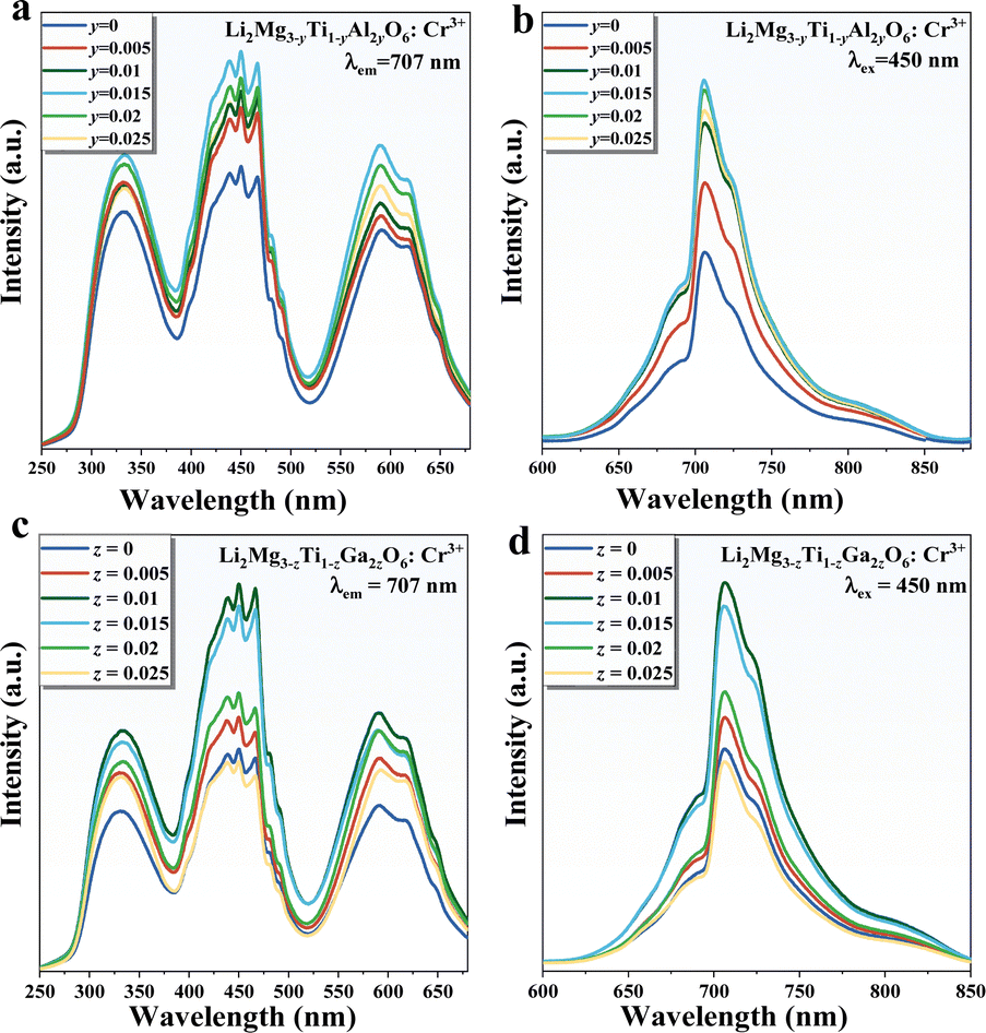
Fig. 3 shows the excitation and emission spectra following the addition of the Al3+–Al3+ and Ga3+–Ga3+ ion pairs. When the ion pair replaces the Mg2+–Ti4+ ion pair in small amounts, the luminescence of the material appears to be significantly enhanced and the spectrum is unchanged. As the amount of substitution continues to increase, the luminescence appears to diminish, with the optimum concentrations of 0.015 and 0.01 for the two substitution strategies, enhancing the luminescence to 180% and 184%, respectively.
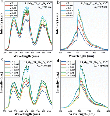 |
| | Fig. 3 (a) and (b) Excitation and emission patterns of LMTO:Cr3+ after Al3+–Al3+ substitution; (c) and (d) excitation and emission patterns of LMTO:Cr3+ after Ga3+–Ga3+ substitution. | |
3.3. Reflectance spectra and optical bandgap
Fig. 4a shows the diffuse reflectance spectra of the LMTO host, LMTO:Cr3+, LMTAO:Cr3+ and LMTGO:Cr3+, and the excitation spectra at 707 nm were chosen to correspond to them. The test interval for diffuse reflectance is from 800 nm to 200 nm, with the LMTO host appearing as an almost flat line in the 800–400 nm range, with a sharp dip after 400 nm. Three valleys of varying intensity appear in the region around 600 nm, 500–400 nm, and 400–300 nm, which correspond to the 4A2 → 4T2, 4A2 → 4T1 and Cr–O charge transfer bands, consistent with the excitation spectrum. In addition, it can be observed that the reflectance of the chemical unit co-substituted material becomes lower, demonstrating stronger absorption. LMGT:Cr3+ absorption is stronger, again corresponding to the results of the fluorescence spectrum. The band gap (Egap) was calculated by the following equation:35–37| | | F(R∞) = (1 − R∞)2/(2R∞) | (6) |
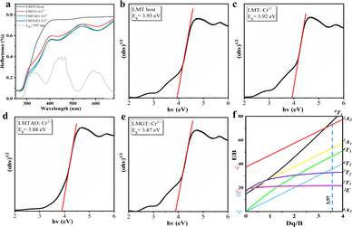 |
| | Fig. 4 (a) Diffuse reflectance spectra and optical band gaps of (b) LMTO:host, (c) LMTO:Cr3+, (d) LMTAO:Cr3+ and (e) LMTGO:Cr3+, (f) the Tanabee–Sugano energy level diagram for d3 electron configuration. | |
R
∞ represents the reflectance, α is the absorption parameter, hν is a proportional constant, n is defined as 1/2, and Eg is the optical band gap. The calculated optical band gaps for the four materials are 3.93 eV, 3.92 eV, 3.88 eV and 3.87 eV (Fig. 4b–e). There is a slight tendency for the band gaps to become smaller, making electron–hole recombination easier.
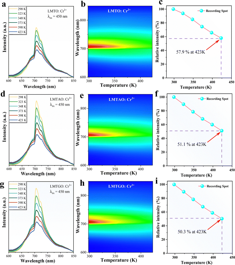
3.4. Temperature-dependent luminescence and quantum efficiency
The elevated internal temperature of the phosphor induces heightened non-radiative transitions and consequent energy dissipation. More than that, large current will cause pc-LED high power operation, resulting in a lot of heat. In plant lighting, it is difficult to use high power radiator discharge heat, and the accumulated heat will seriously affect the performance of the phosphor, so it is very necessary to evaluate the resistance of the phosphor to the high temperature environment. The luminescence properties of phosphors from 298 K to 423 K are tested. As the temperature increases (Fig. 5a–c), the luminous intensity of LMTO:Cr3+ decreases significantly. When it reaches 423 K, the luminous intensity retains 57.9% of that at room temperature. The two materials after co-substitution of chemical units are shown in Fig. 5d–i. Similarly, with the increase of temperature, the luminescence properties of the materials decrease, which may be due to the structural stiffness of the materials decreases after the co-substitution of chemical units, leading to the increase of energy lost by non-radiative transitions. In order to verify this conjecture, the thermal quenching activation energy of phosphor was calculated by the following Arrhenius formula:38| | 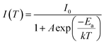 | (8) |
 |
| | Fig. 5 (a)–(c) Temperature dependent luminescence spectra of LMTO:Cr3+ from 298 K to 423 K; (d)–(f) temperature-dependent emission spectra of LMTAO:Cr3+; (g)–(i) temperature-dependent emission spectra of LMTGO:Cr3+. | |
I
0 and I(T) represent the emission intensity at room temperature and at temperature T respectively, k is Boltzmann's constant (k = 8.62 × 10⁻⁵ eV), and A is a constant.
The mechanism can also be better understood by plotting configuration coordinates (Fig. S2, ESI†): when receiving energy, electrons transition from the ground state to the excited state, then some return to the ground state by radiative transition, and others return to the ground state by non-radiative transition at the intersection of the 4A2 and 4T2 energy levels, resulting in a loss of energy. The vertical distance from the intersection of 4A2 and 4T2 to the bottom of the 4A2 level is the thermal quenching activation energy. The calculated Ea values of LMTO:Cr3+, LMTAO:Cr3+ and LMTGO:Cr3+ are 0.283 eV, 0.246 eV and 0.245 eV (Fig. 6(a–c)), respectively. The decrease of thermal quenching activation energy shows that the thermal quenching resistance of phosphor decreases, which is consistent with the experimental results.
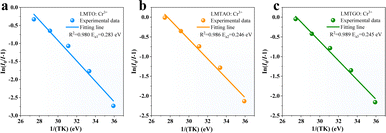 |
| | Fig. 6 Thermal quenching activation energy of (a) LMTO:Cr3+, (b) LMTAO:Cr3+ and (c) LMTGO:Cr3+. | |
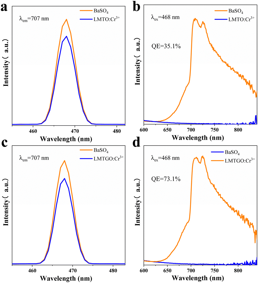
Quantum efficiency is an important parameter to evaluate the performance of phosphors. After testing and calculation, the quantum yield of LMTO:Cr3+ and LMTGO:Cr3+ is increased from 35.1% to 73.1% (Fig. 7). The quantum yield can be derived from the following formula:39
| |  | (9) |
 |
| | Fig. 7 Quantum efficiency of (a) and (b) LMTO:Cr3+; (c) and (d) LMTGO:Cr3+. | |
In the formula, η represents the internal quantum efficiency, LS represents the sample emission spectrum, ER represents the excitation spectrum of BaSO4, and ES represents the excitation spectrum of the sample.
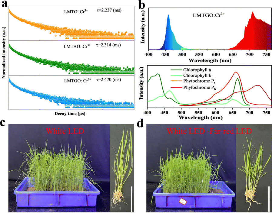
3.5 Fluorescence lifetime characteristics and electroluminescent properties
The fluorescence lifetime of phosphors is shown in Fig. 8a, which is obtained by fitting the following double exponential model:40,41| |  | (10) |
| |  | (11) |
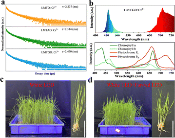 |
| | Fig. 8 (a) The fluorescence lifetime of LMTO:Cr3+, LMTAO:Cr3+ and LMTGO:Cr3+ (b) comparison between the electroluminescence spectra of LMTGO:Cr3+ and the absorption spectra of plant pigments, (c) and (d) rice growing under white light and white light + far red light. | |
Herein, τave represent the average lifetime. The fluorescence lifetime of LMTO:Cr3+, LMTAO:Cr3+ and LMTGO:Cr3+ were 2.237 ms, 2.314 ms and 2.470 ms, respectively.
The LMTGO:Cr3+ phosphor and 450 nm blue light chip were used to package LED devices, and the measured electroluminescent spectrum is shown in Fig. 8b. The obtained far-red emission can be well matched with the Pfr. The overlap after normalization is 61%, indicating that LMTGO:Cr3+ phosphors have good application potential in agriculture.
3.6. Experiment on cold resistance of rice
Rice originated in the tropics and is widely cultivated around the world, with more than half of the world's population relying on rice as their primary food. After rice breeding, it often faces a sudden temperature drop below 10 °C, and even snow and ice weather. This extreme climate can severely affect the physiological state of the rice, negatively affecting its overall metabolism and grain yield. In this work, rice growing under white light was used as a control, and far-red light radiation was added to the experimental group to explore the effect on cold resistance of rice, as shown in Fig. 8c and d.
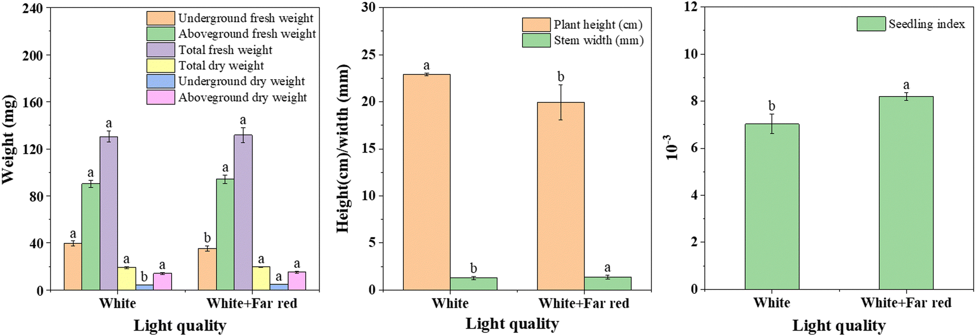
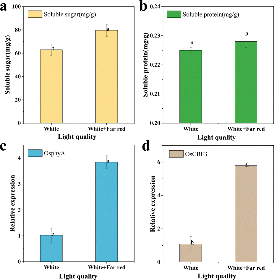
Two groups of rice growing under white light irradiation and far red light + white light irradiation were selected as research objects (Fig. 8c and d). After 15 days of growth, phenotypic images and trait data of rice were obtained, scale bars = 10 cm (c and d). The addition of some far-red light irradiation under white light increased the stem base width and the dry and fresh weights of the above-ground parts of rice (Fig. 9). The plant height decreased by 14.94%, the stem base width increased by 6.29%, and the whole plant fresh weight increased by 1.14%, which finally led to an increase of 16.6% in the sturdy seedling index of rice, which means that rice will be stronger. More importantly, plant traits are generally influenced by gene expression, for example, increased expression of the photosensitive pigments phyA and CBF genes can improve the robustness index of rice by affecting the ABA/GA ratio. To investigate the mechanism of the effect of far-red light on cold tolerance in rice, some representative changes in sugar, protein and gene expression were studied. As shown in Fig. 10, the soluble sugars of rice under far-red light irradiation increased by 26.21% and soluble proteins increased by 1.08%. And for the gene expression, the expression of phyA increased by 277.03% and the expression of CBF3 increased by 425.64%.
 |
| | Fig. 9 Apparent data of rice under white light and white light plus far-red light. Vertical bars present the mean value. Capped bars above represent the standard error. Duncan's multiple range test (P < 0.05) was used to test for differences between averages. | |
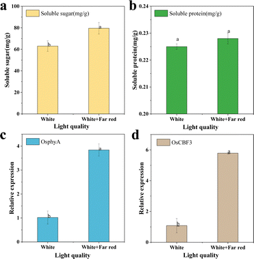 |
| | Fig. 10 (a) Soluble total sugar content, (b) soluble protein content, (c) relative expression of the phyA gene, and (d) relative expression of CBF gene in rice under white light and white light plus far-red light. Vertical bars present the mean value. Capped bars above represent the standard error. Duncan's multiple range test (P < 0.05) was used to test for differences between averages. | |
4. Conclusions
In this work, Li2Mg3TiO6:Cr3+ phosphor was successfully prepared, and XRD patterns showed that the material was successfully synthesized and did not contain other impurities. The photoexcitation spectra show that the material has an optimal excitation band of 400–500 nm and an emission band of 600–850 nm (peak at 707 nm). By replacing Mg2+–Ti4+ with Ga3+–Ga3+ and Al3+–Al3+ ions, the luminosity of the Li2Mg3TiO6:Cr3+ phosphors increased by 180% and 184%, respectively, with a slight thermal quenching (from 57.9% to 51.1% and 50.3%, respectively, at 423 K). The variation in luminous properties is explained by the thermal activation energy and the optical band gap. Even more exciting is that the quantum efficiency of the phosphor has been improved by 2.08 times. After conducting experiments on rice growth, it was found that rice irradiated with far-red light had better resistance to cold, which could be analyzed and explained at the epigenetic and genetic level: plant height and stem width decreased, seedling strength index increased by 16.6%, soluble total sugar increased by 26.21%, soluble protein increased by 1.08%, OsphyB expression increased by 277.03%, and CBF3 expression increased by 425.64%. Such an exciting result is a sign of the excellent application of this job in the field of biological lighting.
Author contributions
Yibiao Ma: conceptualization, data curation and writing – original draft. Siying Li and Jiaqi Wei: conceptualization, data curation. Ming Cheng and Xiaoyan Chen: investigation and formal analysis. Beibei Quan and Weifang Liao: data curation. Maxim S. Molokeev: data curation and formal analysis. Zhi Zhou and Mao Xia: resources, writing – review & editing and supervision.
Conflicts of interest
There are no conflicts to declare.
Acknowledgements
This work was supported by the National Natural Science Foundation of China (Grant No. 51974123), the Key R & D Projects in Hunan Province (2021SK2047 and 2022NK2044), the Natural Science Foundation of Hunan Province, China (Grant No. 2021JJ40261), the Wangcheng Science and Technology Plan (KJ221017), and the Science and Technology Innovation Program of Hunan Province (2022WZ1022). The work was supported by the Ministry of Science and Higher Education of the Russian Federation as part of World-class Research Center program: “Advanced Digital Technologies”, contract no. 075-15-2020-935. Research Foundation of Education Bureau of Hunan Province, China (22B0211).
Notes and references
- G. Annadurai, B. Devakumar, H. Guo, R. Vijayakumar, B. Li, L. Sun, X. Huang, K. Wang and X. W. Sun, RSC Adv., 2018, 8, 23323–23331 RSC.
- X. Huang and H. Guo, Dyes Pigm., 2018, 152, 36–42 CrossRef CAS.
- S. Zhang, S. Gai, X. Zhang, M. Xia, Z. Zhou, X. Cheng, M. Yao, M. S. Molokeev and Q. Feng, Ceram. Int., 2022, 48, 3070–3080 CrossRef CAS.
- X. J. Kang, W. W. Yang, D. X. Ling, C. A. Y. Jia and W. Lu, Mater. Res. Bull., 2021, 140, 111301 CrossRef CAS.
- Z. Z. Lu, Y. B. Meng, H. Fan, J. Y. Lu, X. Y. Zhong, Y. J. Ou, H. R. Mo and L. Y. Zhou, J. Lumin., 2021, 236, 118100 CrossRef CAS.
- N. Yeh and J.-P. Chung, Renewable Sustainable Energy Rev., 2009, 13, 2175–2180 CrossRef CAS.
- A. Sadanandom, E. Adam, B. Orosa, A. Viczian, C. Klose, C. J. Zhang, E. M. Josse, L. Kozma-Bognar and F. Nagy, Proc. Natl. Acad. Sci. U. S. A., 2015, 112, 11108–11113 CrossRef CAS PubMed.
- Z. Zhou, M. Xia, Y. Zhong, S. Gai, S. Huang, Y. Tian, X. Lu and N. Zhou, J. Mater. Chem. C, 2017, 5, 8201–8210 RSC.
- Z. Zhou, J. Zheng, R. Shi, N. Zhang, J. Chen, R. Zhang, H. Suo, E. M. Goldys and C. Guo, ACS Appl. Mater. Interface, 2017, 9, 6177–6185 CrossRef CAS PubMed.
- D. J. Sheerin and A. Hiltbrunner, Plant, Cell Environ., 2017, 40, 2509–2529 CrossRef CAS PubMed.
- M.-H. Fang, G. N. A. De Guzman, Z. Bao, N. Majewska, S. Mahlik, M. Grinberg, G. Leniec, S. M. Kaczmarek, C.-W. Yang, K.-M. Lu, H.-S. Sheu, S.-F. Hu and R.-S. Liu, J. Mater. Chem. C, 2020, 8, 11013–11017 RSC.
- S. Gai, C. Zhou, L. Peng, M. Wu, P. Gao, L. Su, M. S. Molokeev and M. Xia, Mater. Today Chem., 2022, 26, 101107 CrossRef CAS.
- S. Y. Li, Q. Zhu, X. D. Sun and J. G. Li, J. Mater. Chem. C, 2021, 9, 7163–7173 RSC.
- Y. Zhang, Y. Huang, M. Li, C. Liang, H. Zhu, Y. Zhong, N. Yang, Z. Zhou and M. Xia, J. Am. Ceram. Soc., 2020, 103, 4373–4383 CrossRef CAS.
- K. Sankarasubramanian, B. Devakumar, G. Annadurai, L. Sun, Y. J. Zeng and X. Huang, RSC Adv., 2018, 8, 30223–30229 RSC.
- C. Zhou, L. Peng, Z. H. Kong, M. H. Wu, M. S. Molokeev, Z. Zhou, J. Wang and M. Xia, J. Mater. Chem. C, 2022, 10, 5829–5839 RSC.
- S. Zhang, Y. Liu, J. Yin, X. Zhang, Y. Li, L. Su, Z. Zhou and M. Xia, Mater. Today Chem., 2022, 24, 100835 CrossRef CAS.
- D. Yu, Y. Zhou, C. Ma, J. H. Melman, K. M. Baroudi, M. LaCapra and R. E. Riman, ACS Appl. Electron. Mater., 2019, 1, 2325–2333 CrossRef CAS PubMed.
- C. Lee, Z. Bao, M. H. Fang, T. Lesniewski, S. Mahlik, M. Grinberg, G. Leniec, S. M. Kaczmarek, M. G. Brik, Y. T. Tsai, T. L. Tsai and R. S. Liu, Inorg. Chem., 2020, 59, 376–385 CrossRef CAS PubMed.
- D. X. Shi, Z. B. Liang, X. Zhang, Q. Zhou, Z. L. Wang, M. M. Wu and Y. Q. Ye, J. Lumin., 2020, 226, 117491 CrossRef CAS.
- J. L. Pascual, J. Phys. Chem. C, 2019, 123, 27150–27164 CrossRef CAS.
- D. Wu, H. Wu, Y. Xiao, X. L. Dong, Y. Wang, W. P. Zhou, Y. F. Liu and L. L. Zhang, J. Lumin., 2022, 244, 118750 CrossRef CAS.
- X. Zou, X. Wang, H. Zhang, Y. Kang, X. Yang, X. Zhang, M. S. Molokeev and B. Lei, Chem. Eng. J., 2022, 428, 132003 CrossRef CAS.
- E. T. Basore, H. J. Wu, W. G. Xiao, G. J. Zheng, X. F. Liu and J. R. Qiu, Adv. Opt. Mater., 2021, 9, 2001660 CrossRef CAS.
- Y. Zhong, S. J. Gai, M. Xia, S. M. Gu, Y. L. Zhang, X. B. Wu, J. Wang, N. Zhou and Z. Zhou, Chem. Eng. J., 2019, 374, 381–391 CrossRef.
- X. J. Zhang, Y. B. Ma, P. X. Gao, L. J. Su, Z. T. Zhang, Z. Zhou, X. Y. Lu and M. Xia, Ceram. Int., 2022, 48, 29547–29553 CrossRef CAS.
- T. Tan, S. W. Wang, J. Y. Su, W. H. Yuan, H. Y. Wu, R. Pang, J. T. Wang, C. Y. Li and H. J. Zhang, ACS Sustainable Chem. Eng., 2022, 10, 3839–3850 CrossRef CAS.
- F. Zhao, H. Cai, Z. Song and Q. Liu, Chem. Mater., 2021, 33, 3621–3630 CrossRef CAS.
- Z. Jia, C. Yuan, Y. Liu, X. J. Wang, P. Sun, L. Wang, H. Jiang and J. Jiang, Light: Sci. Appl., 2020, 9, 86 CrossRef CAS PubMed.
- Q. Wang, Z. Mu, S. Zhang, Q. Zhang, D. Zhu, J. Feng, Q. Du and F. Wu, J. Lumin., 2019, 206, 618–623 CrossRef CAS.
- M. Zhao, S. Q. Liu, H. Cai, F. Y. Zhao, Z. Song and Q. L. Liu, Sci. China Mater., 2022, 65, 748–756 CrossRef CAS.
- S. Fang, T. Lang, T. Han, M. Cai, S. Cao, L. Peng, B. Liu, Y. Zhong, A. N. Yakovlev and V. I. Korepanov, J. Mater. Chem. C, 2020, 8, 6245–6253 RSC.
- Q. Wang, Z. Liang, J. Luo, Y. Yang, Z. Mu, X. Zhang, H. Dong and F. Wu, Ceram. Int., 2020, 46, 5008–5014 CrossRef CAS.
- Q. S. Wu, Y. J. Xie, F. She, Q. Zhao, J. Y. Ding and J. C. Zhou, J. Rare Earth, 2021, 39, 1040–1048 CrossRef CAS.
- Y. Fu, P. Xiong, X. Liu, X. Wang, S. Wu, Q. Liu, M. Peng and Y. Chen, J. Mater. Chem. C, 2021, 9, 303–312 RSC.
- L. Zhang, D. Wang, Z. Hao, X. Zhang, Gh Pan, H. Wu and J. Zhang, Adv. Opt. Mater., 2019, 7, 1900185 CrossRef.
- T. C. Lang, M. S. Cai, S. Q. Fang, T. Han, S. S. He, Q. Y. Wang, G. H. Ge, J. Wang, C. Z. Guo, L. L. Peng, S. X. Cao, B. T. Liu, V. I. Korepanov, A. N. Yakovlev and J. B. Qiu, Adv. Opt. Mater., 2022, 10, 2101633 CrossRef CAS.
- D. Liu, X. Yun, P. Dang, H. Lian, M. Shang, G. Li and J. Lin, Chem. Mater., 2020, 32, 3065–3077 CrossRef CAS.
- N. Ma, W. Li, B. Devakumar, Z. Zhang and X. Huang, Mater. Today Chem., 2021, 21, 100512 CrossRef CAS.
- E. Song, X. Jiang, Y. Zhou, Z. Lin, S. Ye, Z. Xia and Q. Zhang, Adv. Opt. Mater., 2019, 7, 1901105 CrossRef CAS.
- H. Z. Zhang, J. Zhang, Y. C. Su and X. M. Zhang, Adv. Opt. Mater., 2022, 10, 2200150 CrossRef CAS.
|
| This journal is © The Royal Society of Chemistry 2023 |
Click here to see how this site uses Cookies. View our privacy policy here. 
 Open Access Article
 This Open Access Article is licensed under a Creative Commons Attribution-Non Commercial 3.0 Unported Licence
 *ab and
Mao
Xia
*ab
*ab and
Mao
Xia
*ab