
 Open Access Article
 This Open Access Article is licensed under a
 Creative Commons Attribution 3.0 Unported Licence
Robust MOF-on-MOF heterostructures as efficient cathode candidates for next-generation supercapacitors†
Rakesh
Deka
a,
Viresh
Kumar
a and
Shaikh M
Mobin
 *abc
*abc
aDepartment of Chemistry, Indian Institute of Technology Indore, Khandwa Road, Simrol, Indore 453552, India. E-mail: xray@iiti.ac.in; Tel: +91 731 6603 336
bCenter for Electric Vehicle and Intelligent Transport System (CEVITS), Indian Institute of Technology Indore, Khandwa Road, Simrol, Indore 453552, India
cCenter of Advanced Electronics (CAE), Indian Institute of Technology Indore, Khandwa Road, Simrol, Indore 453552, India
First published on 10th November 2023
Abstract
Metal–organic frameworks (MOFs) have shown great potential as cathode in supercapacitor applications. However, they can also be used as a platform for designing a new class of materials. Herein, a MOF-on-MOF heterostructure, Ni-BTC@ZIF-67, has been synthesized via a solvothermal method followed by the in situ growth of ZIF-67 on Ni-BTC and was well-characterized through various techniques (PXRD, FT-IR, BET, SEM, TEM, and XPS). From SEM, TEM, and XPS analysis, it is clear that ZIF-67 was successfully deposited over the Ni-BTC surface via N–O bonding interaction. One potential application of Ni-BTC@ZIF-67 is as an electro-active material in the construction of supercapacitors. This material demonstrated an impressive specific capacitance of 1063 F g−1 when subjected to a 4 A g−1 current. The robust nature of both MOFs helped attain a cyclic retention capacity of about ∼98% after 5500 cycles. Moreover, an asymmetric supercapacitor was assembled with activated carbon and Ni-BTC@ZIF-67 in an aqueous system, which delivered an energy density of 22 W h Kg−1 at a power density of 1075 W Kg−1 with a cyclic retention of ∼83% after 1000 cycles. Thus, the MOF-on-MOF architecture can be a new pathway for supercapacitor applications in the future.
1. Introduction
The human race requires energy as an essential resource for survival. The rapid growth of environmental pollution due to fossil fuel consumption and energy crises has compelled the need to develop novel approaches for other renewable and clean energy production for daily use. Although clean energy sources, like wind, tide, and sun, can play a significant role in meeting the demand for sustainable energy,1,2 electrochemical energy storage devices, such as batteries, supercapacitors (SCs), and fuel cells, are more suitable because these energy sources can be utilized at any given time and in weather conditions. Among these, SCs are one of the electrical energy storage devices that can be a reliable and efficient device that have received tremendous importance in recent years owing to their quick charging–discharging process, higher power density, high safety, and stable recyclability.3–5 The primary mechanism of SCs is the electrostatic charge deposition process. This energy can be further utilized by electric devices or for charging batteries.While batteries store energy via chemical processes, SCs store it by accumulating electrons on their electrodes.6 This helps supercapacitors undergo a quick charge–discharge process, and hence they can be utilized in power backup stations, electrical power smoothing, and regenerative braking systems in electric vehicles.7 Eventually, a supercapacitor is more advantageous than batteries in the following ways:7,8 (i) faster energy storage and release efficiency; (ii) free of toxic chemicals and does not produce any hazardous waste; and (iii) high power density, i.e., quick release of a high quantity of power, which makes them ideal for applications that require large amounts of energy to be delivered quickly, such as in electric vehicles, wherein they can help improve the performance and efficiency. Despite these advantages, there are some limitations in SCs, such as a low energy density, high self-discharge rate and manufacturing cost, which hinder its wide application toward meeting the global energy demand.9,10 However, progress in research can address these limitations by manufacturing advanced materials for efficient SCs as they are expected to be essential for transitioning to a more sustainable energy future.
There are two main types of SCs: (i) electrochemical double-layer capacitors (EDLCs): these are standard supercapacitors based on carbonaceous materials and are known as “electric double-layer capacitors” or “carbon capacitors”. The principle of EDLCs is to store charge through charge separation at the electrode–electrolyte interface, which forms a double layer of charge;11 (ii) pseudocapacitors: the basic working principle of pseudocapacitors is charge transfer rather than charge separation. Various metal oxides (CO3O4, NiO, MnO2, etc.), and conducting polymers (PANI, polypyrrole, etc.) fall in this category and store charge via electrochemical reactions at the electrode–electrolyte junction. They have advantages over EDLCs in terms of energy density but are more expensive to produce.11 Ruthenium-based oxide (RuO2·xH2O) is an interesting pseudocapacitive material.12,13 The diffusion and intercalation of protons into the bulk of this material offer high specific capacitance values. The crystalline and hydrous nature of ruthenium-based oxide not only reduces the proton diffusion resistance but also enhances the electronic conductivity, facilitating the redox transitions of the active species.13 Moreover, the mixed proton- and electron-conducting nature of hydrous ruthenium oxide plays an important role in its application as an electrocatalyst in direct methanol fuel cells and enhanced redox capacitance.14,15 Besides, it also exhibits improved diffusion-limited capacitance, which is facilitated by the more open framework in the case of exfoliated ruthenium oxide nanosheets.16,17 There are other reports on the application of pseudocapacitive materials like vanadium oxide and tungsten oxide in high-voltage supercapacitors.18,19
Various materials, such as 2D materials20 (MXene,21–23 MoS2,24,25 reduced graphene oxide,26,27etc.), porous materials (coordination polymer,28,29 metal–organic frameworks (MOFs),30–33 covalent organic frameworks,34–36etc.), nanomaterials37 (carbon dots,38 transition metal oxide,39,40etc.), (Fe, Co, Ni) molybdenumdisulfide,41 and nano MOFs,42 have been explored for supercapacitor application so far. However, MOFs are one of the most exciting materials due to several advantages, including tunable pore size, high surface area, and tunable structural properties, which make them ideal for application in SCs.43,44 Moreover, from readily available precursor materials (benzene dicarboxylic acid, terephthalic acid, 2-methyl imidazole, and various metal salts), MOFs can be synthesized on a large scale for use as electroactive materials for supercapacitors.
Moreover, MOFs have enabled the design of a new class of electroactive materials for SCs by incorporating active organic groups and conductive metal ions.45,46 Developing MOF-on-MOF architectures is one of the highly unique approaches that can be utilized for energy storage applications. A MOF-on-MOF structure can be achieved by depositing a thin layer of a conductive MOF on a thicker layer of a supportive MOF.47 These MOFs are effective in improving ionic conductivity, reducing diffusion limitations, and offering high surface area for efficient electrochemical performance. There are several advantages to using MOF-on-MOF structures, such as48,49 (i) higher energy density and power density, (ii) versatility with MOF selection and functionalization, (iii) various MOFs can be used to customize structures with tailored properties, leading to optimized energy storage performance, i.e., one of the MOFs can provide high surface area, and the other can provide higher conductivity, (iv) their low-cost and environment-friendly nature helps bulk production for commercial use, and (v) the robust nature of the MOF structure makes them stable. So far, MOF-on-MOF architectures have been utilized for various applications like catalysis, separation, sensing, water treatment, pesticide removal, and oxygen evolution reaction50–53 However, the application of MOF-on-MOF in supercapacitors is still in the initial stages of development and requires attention to improving the performance and stability.
Using a material that includes a metal–organic framework made of the Ni and Co bimetal system has shown promising supercapacitor performance.54–56 Moreover, individually, Ni-BTC and ZIF-67 show good supercapacitor properties.57,58 So far, NiCo2O4@graphene nanorods synthesized by utilizing ZIF-67@Ni-BTC have been explored for lithium storage properties.59 However, the potential of MOF-on-MOF materials, specifically Ni-BTC@ZIF-67, in supercapacitors remains unexplored in the realm of energy storage applications. Therefore, our current study focuses on unraveling the capabilities of Ni-BTC@ZIF-67 as a promising material for supercapacitors. Its advantages include (i) a simple synthetic route that involves hydrothermal-assisted room-temperature synthesis without any harsh reaction conditions, (ii) the presence of the redox-active couples Ni2+/Ni+3 and Co2+/Co3+ may further enhance the electrochemical properties, and (iii) the easy fabrication technique of Ni-BTC@ZIF-67 without the addition of a binder and additive may reduce the production and manufacturing cost. These facts make it an ideal material for supercapacitor applications. In this work, we have synthesized an electroactive material with the MOF-on-MOF architecture (Ni-BTC@ZIF-67) from Ni-BTC and ZIF-67 by a simple solvothermal process followed by the in situ growth of ZIF-67 on Ni-BTC. Primarily, the Ni-BTC MOF synthesized via a solvothermal route acted as a support for the Ni-BTC@ZIF-67 electrode. The morphological and structural characterization confirms the successful deposition of ZIF-67 on the Ni-BTC surface. With an impressive retention rate of approximately 98%, the synthesized Ni-BTC@ZIF-67 material could offer a specific capacitance (Cs) of 1063 F g−1 at 4 A g−1. Moreover, an asymmetric supercapacitor was assembled with Ni-BTC@ZIF-67 as an active material. The supercapacitor was found to possess 22 W h Kg−1 energy density and 1075 W Kg−1 power density, indicating that it has the potential to function as a highly efficient energy storage device. Moreover, it maintained approximately 83% of its initial capacity after the 1000 cycle test. Therefore, the potential benefits of MOF-on-MOF, with continued research and development, may lead to significant advances in energy storage technology in the future.
2. Experimental section
2.1. Materials
The chemicals utilized in the study were obtained from commercial sources and used without any purification. Finar and Merck chemicals were the suppliers of Ni(NO3)2·6H2O, Co(NO3)2·6H2O, 2-methylimidazole, trimesic acid (BTC), N,N-dimethylformamide (DMF), methanol, and KOH. The aqueous KOH solutions were prepared using de-ionized water. For further details regarding instrumentation, refer to the ESI.†2.2. Synthesis of ZIF-67, Ni-BTC and Ni-BTC@ZIF-67
The synthesis of ZIF-67 was carried out according to the literature.60 In a typical reaction, Co(NO3)2·6H2O (0.582 g, 2 mmol) was solubilized in 40 mL methanol, and 2-methylimidazole (1.32 g, 16 mmol) was dissolved separately in 20 mL methanol; both the solutions were mixed thoroughly by stirring and left for over 2 hours at room temperature. After 2 hours, the resultant blue powder was centrifuged and washed several times with methanol and dried at 80 °C for 6 h in a tube furnace.To synthesize Ni-BTC MOF,61 trimesic acid (BTC) (0.105 g, 0.50 mmol) and Ni(NO3)2·6H2O (0.872 g, 3 mmol) in the trimesic acid: Ni2+ ratio of (1![[thin space (1/6-em)]](https://www.rsc.org/images/entities/char_2009.gif) :6) was dissolved in 60 mL DMF and stirred for about an hour. The resultant solution was shifted to a Teflon-lined autoclave and reacted for 12 hours at 150 °C. The obtained green-coloured precipitate was washed several times with DMF and ethanol by centrifugation. Consequently, the obtained green powder was dried at 80 °C for 8 h in a tube furnace.
:6) was dissolved in 60 mL DMF and stirred for about an hour. The resultant solution was shifted to a Teflon-lined autoclave and reacted for 12 hours at 150 °C. The obtained green-coloured precipitate was washed several times with DMF and ethanol by centrifugation. Consequently, the obtained green powder was dried at 80 °C for 8 h in a tube furnace.
Finally, Ni-BTC@ZIF-67 was synthesized by the following synthetic approach: in a typical reaction, approximately 300 mg of the synthesized Ni-BTC MOF was dispersed in 75 mL of methanol via sonication for around 60 min. Then, the above dispersion was transferred to a round-bottomed flask along with magnetic beads and stirred. After that, Co(NO3)2·6H2O (3.75 mmol) was mixed with the above mixture and stirred further for 40 min. Moreover, 15 mmol 2-methylimidazole dissolved in 75 mL of methanol was added slowly to the above reaction mixture. The whole mixture was stirred further for another 3 hours. The resultant blue-coloured precipitate was then washed multiple times with methanol by centrifugation. Finally, the resultant powder was dried at 80 °C for 8 hours in a tube furnace.
2.3. Electrochemical studies
The details of the electrochemical setup, electrode fabrication, and efficiency evaluation formulae are provided in the ESI.†3. Results and discussion
The synthetic procedure of Ni-BTC@ZIF-67 detailed in the experimental section is shown in Scheme 1. ZIF-67 was grown in situ on Ni-BTC, which was synthesized using a solvothermal method.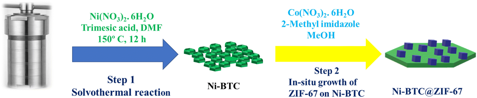 | ||
| Scheme 1 A schematic representation of the multi-step process used for Ni-BTC@ZIF-67 synthesis. | ||
The XRD patterns of Ni-BTC, ZIF-67, and Ni-BTC@ZIF-67 are shown in Fig. 1a. The peaks observed at 2θ° values of 7.2, 10.3, 12.7, 14.6, 16.4, 18.0, 22.1, 24.4, and 26.8 confirm the formation of ZIF-67 according to earlier reports.62 Moreover, in the XRD pattern of 1:6 Ni-BTC, the peaks at 2θ° values of 11.8, 17.9, 20.8, 22.2, 23.8, 33.4, and 59.6 confirm the formation of Ni-BTC according to the literature.63,64 The XRD pattern of Ni-BTC@ZIF-67 showed peaks at 2θ° values of 7.2, 10.3, 12.7, 14.6, 16.4, 17.9, 22.1, 24.4, and 26.76 confirm the presence of ZIF-67. Moreover, the other peaks at 2θ° = 11.7, 17.9, 20.8, 22.2, 23.7, 33.4, and 59.6 could be attributed to Ni-BTC. Therefore, the PXRD result indicates the successful incorporation of Ni-BTC and ZIF-67 in Ni-BTC@ZIF-67.
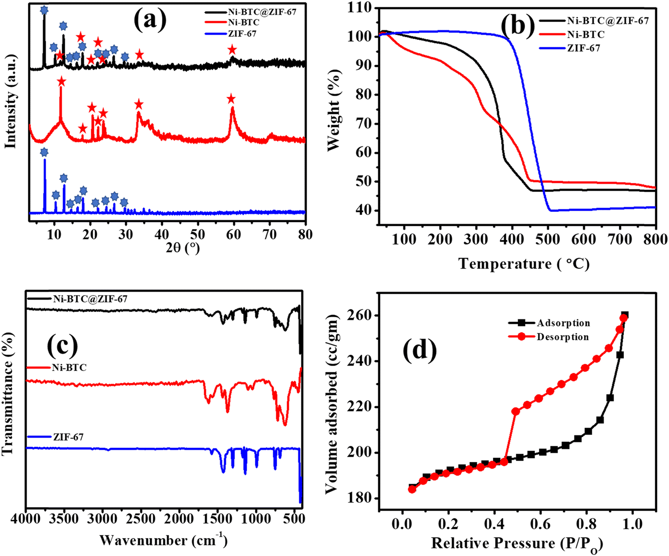 | ||
| Fig. 1 (a) The PXRD patterns, (b) TGA, (c) FT-IR spectra of Ni-BTC@ZIF-67, Ni-BTC, and ZIF-67, and (d) the BET curve of Ni-BTC@ZIF-67. | ||
The thermal stability of the synthesized material was analyzed by thermogravimetric analysis (TGA) (Fig. 1b). The TGA curves of Ni-BTC and Ni-BTC@ZIF-67 indicated an initial weight loss up to 150 °C due to the loss of associated water and CH3OH molecules. The second phase of weight loss up to 330 °C is due to the release of DMF molecules, co-ordinated BTC and a water molecule. However, the complete degradation of the frameworks was observed from 350 to 450 °C. The pattern of synthesized Ni-BTC@ZIF-67 resembled the TGA patterns of both ZIF-67 and Ni-BTC, confirming the successful incorporation of both materials.65
To gain further insights into the successful incorporation of ZIF-67 onto Ni-BTC, the FT-IR spectra were recorded over the frequency range of 400–4000 cm−1 (Fig. 1c). The bands observed at 1620 cm−1, and 1370 cm−1 correspond to the asymmetric and symmetric vibration modes of the carboxylate groups present in Ni-BTC.66 The band at 715 cm−1 is due to the C–C group stretching vibration mode and the in-plane and out-of-plane distortion vibrations of the C–H groups of the benzene ring.67 Moreover, for ZIF-67, the observed band at 757–1413 cm−1 could be related to the bending and stretching vibration modes of the imidazole ring.68 The observed band at 1586 cm−1 depicts the stretching vibrational mode of the C–N bond present in 2-methylimidazole.69 Thus, the characteristic bands observed for Ni-BTC and ZIF-67 suggest the successful preparation of the bare MOFs. In the case of Ni-BTC@ZIF-67, the characteristic peaks of ZIF-67 were observed in the FT-IR spectrum between 757–1413 cm−1, confirming the structural retention of ZIF-67 within the synthesized material. Additionally, the bands at 1620 cm−1 and 1370 cm−1 confirm the presence of Ni-BTC in Ni-BTC@ZIF-67. Therefore, the FT-IR spectrum provides evidence for the successful synthesis of Ni-BTC@ZIF-67, which is crucial for its potential application in various fields.
To determine the surface area and pore size distribution of the synthesized material, N2 adsorption–desorption isotherm measurements were conducted at 77 K (Fig. 1d and Fig. S1–S3, ESI†). The isotherm observed for Ni-BTC@ZIF-67 was a typical type III isotherm. The BET surface area and pore size are summarized in Table S1 (ESI†). The observed surface area of Ni-BTC@ZIF-67 was 746.987 m2 g−1, and the pore radius was 0.85 nm. The process of incorporation of both MOFs blocks the pores of Ni-BTC@ZIF-67 in comparison with the bare MOFs. Therefore, the surface area and pore size of the material were in between the values of the bare MOFs.65 However, the presence of two redox-active centers may lead to better electrochemical performance of the material.70
The scanning electron microscopic (SEM) images of ZIF-67, Ni-BTC, and Ni-BTC@ZIF-67 are displayed in Fig. 2(a–f). The SEM images of ZIF-67 (Fig. 2a and b) reveal a cuboid shape, and Ni-BTC (Fig. 2c and d) shows a hierarchical porous structure. However, the SEM images (Fig. 2e and f) of Ni-BTC@ZIF-67 comprised both types of surface morphologies: (i) cuboid and (ii) hierarchical porous structure. This confirms the satisfactory synthesis of a MOF-on-MOF structure of ZIF-67 and Ni-BTC. Moreover, transmission electron microscopic (TEM) images of Ni-BTC@ZIF-67 were also captured to further verify the presence of both the bare MOFs. The hybrid material with a MOF-on-MOF architecture was synthesized from two isosymmetric MOF structures with different metal ions. The bare MOF structure of Ni-BTC promotes the growth of ZIF-67 on its surface with good connectivity at the interface. The TEM images shown in Fig. 2(g and h) confirm the successful development of the MOF-on-MOF structure in the hybrid material.71 Further, the elemental mapping was also recorded for Ni-BTC@ZIF-67, as shown in Fig. 2(i–m). The homogenous distribution of C, O, N, Ni, and Co elements across the synthesized Ni-BTC@ZIF-67 material was confirmed by the elemental mapping analysis, as illustrated in Fig. S4 (ESI†), thereby providing further evidence of the successful synthesis of the material.
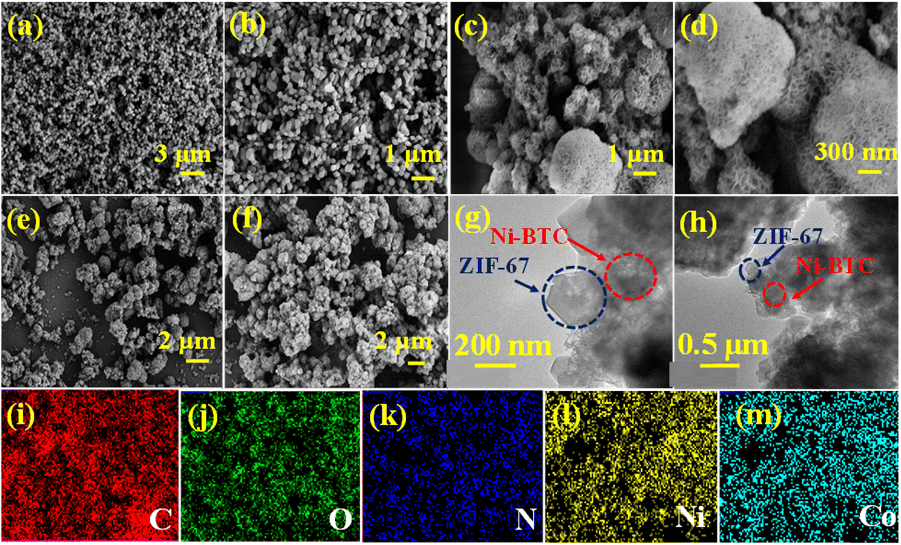 | ||
| Fig. 2 The SEM images of (a) and (b) ZIF-67, (c) and (d) Ni-BTC, and (e) and (f) Ni-BTC@ZIF-67; (g) and (h) the TEM images of Ni-BTC@ZIF-67, and (i)–(m) elemental mapping of Ni-BTC@ZIF-67. | ||
X-ray photoelectron spectroscopy was used to understand the chemical composition and the interaction of electrons in Ni-BTC@ZIF-67. The survey spectrum displayed in Fig. 3a exhibits the presence of C 1s, N 1s, O 1s, Co 2p, and Ni 2p, which agree with the result obtained from EDX mapping. The deconvoluted spectrum of C 1s in Fig. 3b comprises three important peaks at ∼288.5 eV, ∼285.6 eV, and ∼284.8 eV, confirming the presence of C–O, C–N, and C–C bonds, respectively.70 However, as seen in Fig. 3c, the O 1s spectrum could be deconvoluted to three peaks at ∼529.3 eV, ∼531.6 eV, and ∼533.5 eV corresponding to the metal-coordinated oxygen bond,72 O–C bond, and O–N bond, respectively.70 The N 1s spectrum in Fig. 3d is deconvoluted into three major peaks at ∼399.1 eV (–NH–),73 ∼399.22 (N![[double bond, length as m-dash]](https://www.rsc.org/images/entities/char_e001.gif) C)70 and ∼400.95 eV (N–O).70,74 The peak at ∼400.95 eV denoting N–O indicates the strong interaction of the N atom of the imidazole ring in ZIF-67 with the O atom present in Ni-BTC. The Co 2p spectrum in Fig. 3e is fitted into two major peaks at 781.3 eV and 796.4 eV respectively for Co 2p3/2 and Co 2p1/2.73 However, these two peaks are associated with two satellite peaks at ∼788.0 eV {Co 2p3/2(S)}, and ∼803.88 eV {Co 2p1/2(S)} further confirming the existence of cobalt in the Co2+ and Co3+ forms. Moreover, the Ni 2p spectrum in Fig. 3f comprises two major peaks at ∼856.08 eV and ∼873.94 eV related to Ni 2p3/2 and Ni 2p1/2, respectively.75 The two associated peaks at ∼862.09 eV and ∼880.61 eV are the satellite peaks of Ni 2p3/2 and Ni 2p1/2, respectively. Therefore, the peaks at ∼533.5 eV (O–N) and ∼400.95 eV (N–O) further confirm the formation of Ni-BTC@ZIF-67 by the bonding interaction of the imidazole N atom of ZIF-67 and the O atom of Ni-BTC.
C)70 and ∼400.95 eV (N–O).70,74 The peak at ∼400.95 eV denoting N–O indicates the strong interaction of the N atom of the imidazole ring in ZIF-67 with the O atom present in Ni-BTC. The Co 2p spectrum in Fig. 3e is fitted into two major peaks at 781.3 eV and 796.4 eV respectively for Co 2p3/2 and Co 2p1/2.73 However, these two peaks are associated with two satellite peaks at ∼788.0 eV {Co 2p3/2(S)}, and ∼803.88 eV {Co 2p1/2(S)} further confirming the existence of cobalt in the Co2+ and Co3+ forms. Moreover, the Ni 2p spectrum in Fig. 3f comprises two major peaks at ∼856.08 eV and ∼873.94 eV related to Ni 2p3/2 and Ni 2p1/2, respectively.75 The two associated peaks at ∼862.09 eV and ∼880.61 eV are the satellite peaks of Ni 2p3/2 and Ni 2p1/2, respectively. Therefore, the peaks at ∼533.5 eV (O–N) and ∼400.95 eV (N–O) further confirm the formation of Ni-BTC@ZIF-67 by the bonding interaction of the imidazole N atom of ZIF-67 and the O atom of Ni-BTC.
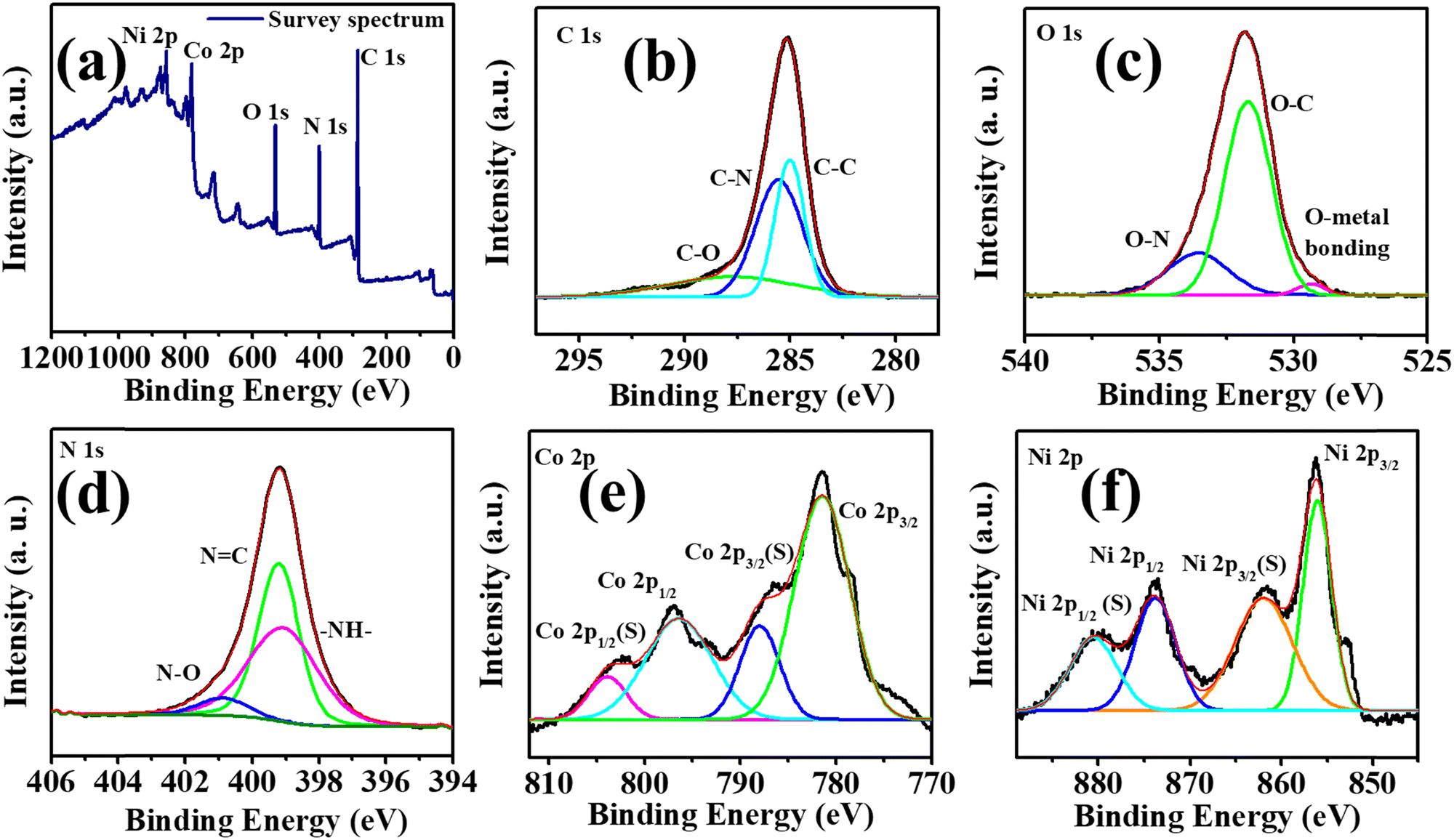 | ||
| Fig. 3 (a) The survey spectrum of Ni-BTC@ZIF-67 and (b)–(f) deconvoluted XPS spectra of C1s, O1s, N1s, Co2p, and Ni2p. | ||
3.1. The electrochemical study of Ni-BTC@ZIF-67
To understand the electrochemical supercapacitor behaviour of Ni-BTC@ZIF-67, Ni-BTC, and ZIF-67, the conventional three-electrode system was used, as described earlier. The active materials were used without the addition of a binder or additive in a 5 M KOH solution (Fig. 4 and Fig. S5, S6, ESI†). At first, a comparative study was carried out with all the materials using the CV and GCD techniques. The relative CV plots in Fig. 4a illustrate that the curve area increased in the order of Ni-BTC@ZIF-67 > Ni-BTC > ZIF-67. The observed results indicate that Ni-BTC@ZIF-67 would show higher electrochemical efficiency than the other materials. This prediction is verified by the comparative GCD plots shown in Fig. 4b. The higher specific capacitance observed for Ni-BTC@ZIF-67 may be due to the presence of two redox active metal centers (Ni, Co), which may comparatively enhance the rate of the redox reactions. However, the synergistic effect of Ni-BTC and ZIF-67 increases the number of catalytic active sites and intrinsic activity, consequently favoring higher charge storage capacity. As Ni-BTC@ZIF-67 delivered the highest Cs value, a detailed electrochemical investigation was carried out using CV and GCD. In Fig. 4c, the CV plots of Ni-BTC@ZIF-67 at various scan rates within the potential window of 0 to 0.48 V are shown. The CV curves clearly demonstrate broad cathodic and anodic peaks with a quasi-rectangular shape, suggesting that the synthesized material shows battery or pseudocapacitor-type behaviour. The observed quasi-rectangular shape is due to the presence of the faradaic redox process and the reversible Ni2+/Ni3+ and Co2+/Co3+ redox couples. It can be observed that with an increment in scan rate, the CV curve area increased, and the corresponding redox peaks shifted towards a more positive and negative direction. This characteristic may arise because of the polarization effect or higher electrode resistance at higher scan rates.76 | ||
| Fig. 4 (a) and (b) The comparative CV and GCD plots of Ni-BTC, ZIF-67, and Ni-BTC@ZIF-67; (c) and (d) CV and GCD plots of Ni-BTC@ZIF-67 at several scan rates and current densities; (e) comparison of the Cs of Ni-BTC, ZIF-67, and Ni-BTC@ZIF-67; and (f) specific capacity curve of Ni-BTC@ZIF-67 in 5 M KOH. | ||
Moreover, the GCD plots of Ni-BTC@ZIF-67 at varying current densities are shown in Fig. 4d. The discharge curve in Fig. 4d comprises two distinct regions. At first, a linear discharge is observed because of the IR drop, which releases the charges near the surface region. Later on, a second region with a continuous discharge tail is observed. This behaviour results from the de-intercalation of the diffused ions from the inner active sites of the material. As the current density gradually increases, the linear region dominates the discharge curve due to the active participation of only the outer surface of the active materials. Fig. 4e represents the comparison of Csvs. current density for all three materials. Ni-BTC@ZIF-67 delivered the maximum Cs of 1063 F g−1 at 4 A g−1. But on the contrary, the synthesized Ni-BTC and ZIF-67 offered only 618 F g−1 and 489 F g−1 at 4 A g−1. It is also seen that with a gradual increment in current density, the observed Cs values decreased. This is because, at higher current densities, the K+ ions from the electrolyte solution have less time to penetrate the electrode, thus mostly accumulating on the electrode surface and consequently resulting in a slower faradaic redox process. Meanwhile, at low current densities, the K+ ions have enough time to use the bulk of the active material; as a result, they reach more accessible active sites and provide a favourable faradaic redox process. Additionally, the specific capacity of Ni-BTC@ZIF-67 was also calculated by using eqn (S2) (ESI†) (Fig. 4f). The observed specific capacity of 101 mA h−1 at 4 A g−1 may be because of the presence of micropores in the active materials, which may provide a faster reaction pathway for the electrochemical reaction.77
To decipher the electrode kinetics, the electrochemical impedance spectra were recorded for all three materials in the frequency range of 0.1 Hz to 105 Hz (Fig. 5a). The equivalent circuit diagram and circuit fitting parameters are illustrated in Fig. S7 and Table S2 (ESI†), respectively. Rs denotes the equivalent series resistance and signifies the solution, electrical, and other contact resistance. The value of Rs was calculated from the Nyquist plot, where the semicircular loop is located at a higher frequency region from the Z′ axis. From Table S2 (ESI†), it is observed that the modified material Ni-BTC@ZIF-67 offers a comparatively lower value of Rs than Ni-BTC and ZIF-67. These results illustrate the better reaction kinetics of Ni-BTC@ZIF-67 over the others, consequently delivering a higher electrochemical efficiency. In addition, double-layer capacitance (Cdl) was also observed at the interface between the surface and the fluid. However, in the higher frequency region, where the impedance value is lower, Cp dominated. However, when the frequency value shifted towards a lower value, the current changed its pathway rather than Cp. Moreover, Rct represents the charge transfer resistance at the junction of the electrode and the electrolyte. Consequently, constant phase elements are also associated in the circuit, denoted as CPE. This parameter signifies the voltage-dependent faradaic charge transfer processes of pseudocapacitance.78
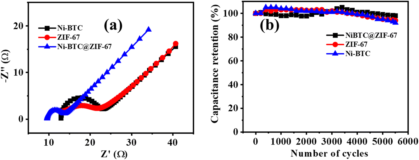 | ||
| Fig. 5 (a) The Nyquist plots, (b) the cyclic stability of Ni-BTC, ZIF-67, and Ni-BTC@ZIF-67. | ||
Further, capacitance retention efficiency in the cyclic test is associated with the stability of a material. Here, the cyclic stability test was conducted up to 5500 repetitive GCD cycles, and ∼98%, ∼94%, and ∼92% capacity retention was observed for Ni-BTC@ZIF-67, ZIF-67, and Ni-BTC, respectively (Fig. 5b). The continuous intercalation/deintercalation of ions at the electrode/electrolyte interface79 may cause the slight degradation of capacitance value. However, initially, after a few hundred cycles, it appeared that the retention curve exceeded more than 100%; this may be due to the activation of the material or the enhancement of wettability after a few cycles.80 During the activation steps, the electrolyte ions may pass through the pores in the material to reach their active sites.81
3.2. Study of the asymmetric solid-state supercapacitor
The study of material performance in solid-state asymmetric supercapacitors is essential to assess its efficiency and practical utility. In this work, the prepared Ni-BTC@ZIF-67 and activated carbon (AC) were used as the cathode and anode electrode materials, respectively, to assemble a device. The mass loadings of both the cathode and anode electrodes in an asymmetric device hold significant importance.82,83 The mass loading of Ni-BTC@ZIF-67 and AC were 0.5 mg cm−2 and 0.5 mg cm−2, respectively. Briefly, the device fabrication included the following steps: at first, the conducting gel electrolyte was prepared by using a PVA/KOH mixture and thoroughly heated up to 353 K by stirring until it became a transparent gel. Moreover, as the gel was prepared, the electrode material was mixed well with the gel system to make a free-flowing liquid. Later, the carbon fiber was cut to particular dimensions (1.5 cm × 3 cm) to deposit the active material. The deposited material was then soaked in the gel for a few minutes and dried at room temperature. Subsequently, both the anode and cathode electrodes were sandwiched to each other with the help of carbon filter paper (Fig. 6a) and closely packed for efficiency evaluation. Afterward, the asymmetric device was connected in series and charged with an AC adapter (300 mA) for a few seconds. The fabricated device was used to light a commercially available red LED (1.8 V) bulb for a few minutes (Fig. 6b). Further, for efficiency evaluation, CV and GCD techniques were used to study the device. Fig. 6c represents the CV plots of the device at several scan rates within the potential window of 0–1.1 V. It was observed that the CV plot area increased with the increment in scan rate, and the overall nature of the CV plot was similar even at higher scan rates. This represents that material stability did not degrade with the increment in scan rate.84 The GCD curves were obtained in the same potential range as CV and are presented in Fig. 6d. The collective effect of the faradaic mechanism of Ni-BTC@ZIF-67 and the surface adsorption/desorption of activated carbon synergistically enhances charge storage and may be responsible for the characteristic GCD curve observed in Fig. 6d.98 The device exhibited a maximum Cs of 132 F g−1 at a current density of 2.0 A g−1, and as the current density was increased to 3.0 A g−1, the observed Cs value decreased (Fig. S8, ESI†). The gradual decrease in capacitance with a rise in current density signifies the poor faradaic redox process at higher current densities.76 Moreover, to compare the device performance the Ni-BTC and ZIF-67 devices were also assembled in a similar way, and their results are included in Fig. S9 and S10 (ESI†). The obtained specific capacitance for the Ni-BTC device was 80 F g−1 at 2 A g−1 and that of the ZIF-67 device was 73 F g−1 at 2 A g−1. These results indicate comparatively low device performance with respect to Ni-BTC@ZIF-67. Later on, the Nyquist plots were recorded for the ASC devices in the frequency range of 0.1 Hz to 105 Hz, as shown in Fig. S11 (ESI†), for all three materials. Table S3 (ESI†) provides the circuit fitting parameters for the devices. The series resistance (Rs) is the intercept along the real axis and comprises ionic and electronic resistance. The charge transfer resistance (Rct) denotes the resistance due to charge transfer during the faradaic process at the electrode–electrolyte junction. CPE represents the pseudocapacitance of the electrode.85 Moreover, the presence of double-layer capacitance (Cdl) was observed at the boundary of the surface and the fluid. Yet, in the higher frequency range, where the impedance is low, Cp was dominant. The observed series resistance of the Ni-BTC@ZIF-67 device was lower in comparison with the bare MOF devices (Table S3, ESI†). This can explain the observed device performances of the materials.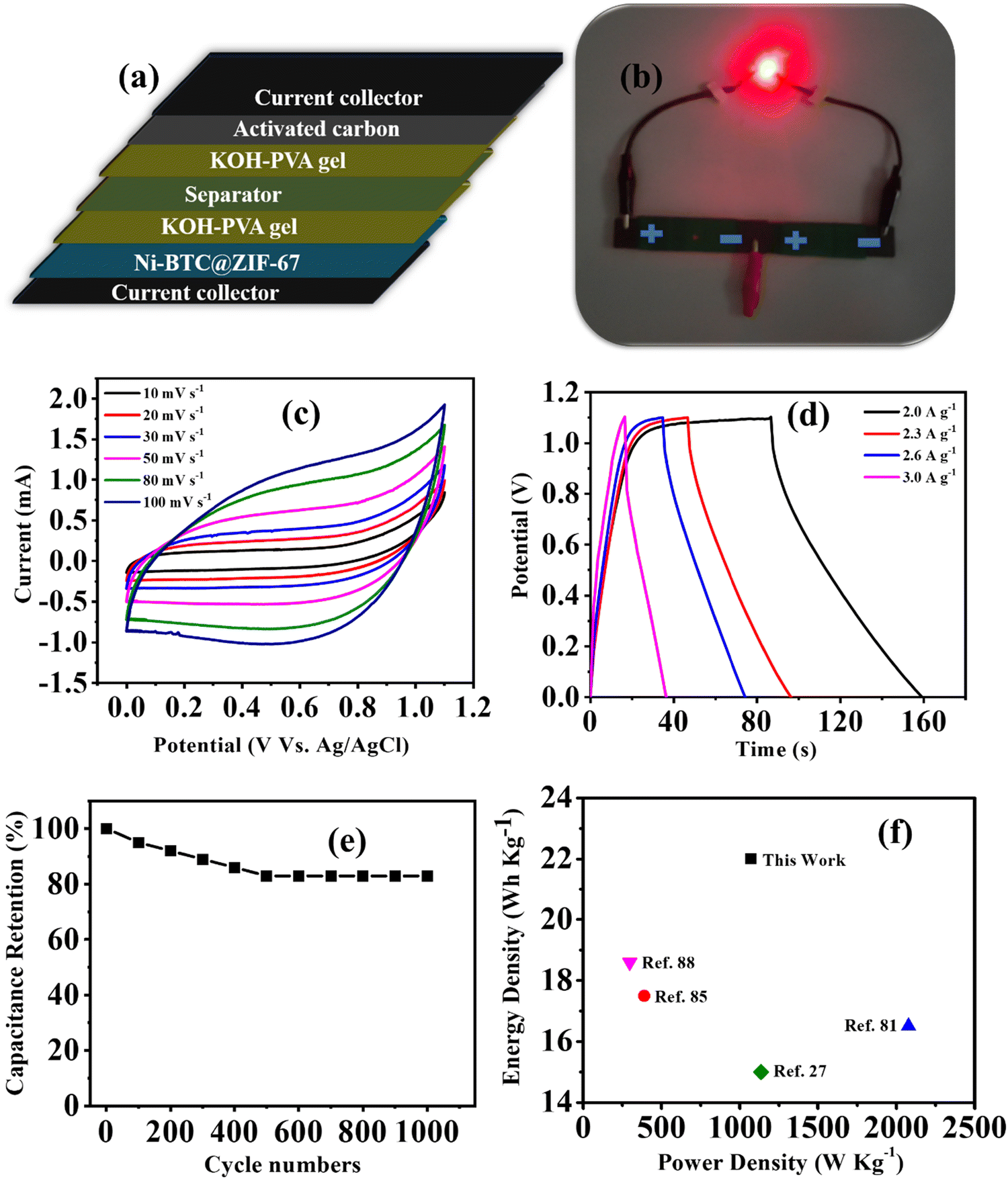 | ||
| Fig. 6 (a) An illustration and (b) representation of the ASC device. (c) The CV plots at different scan rates, (d) GCD curves at different current densities, (e) cyclic stability plot, and (f) Ragone plot for Ni-BTC@ZIF-67. | ||
Moreover, the stability factor is also an important parameter to measure the practical importance of a device. Therefore, we conducted the cyclic stability test for the device through GCD analysis, and after 1000 cycles, the device was found to maintain 83% of its original capacitance (Fig. 6e). Moreover, energy density and power density are essential parameters of any device system. Therefore, the Ragone plot was drawn, as shown in Fig. 6f, and the observed values of energy density and power density were 22 W h Kg−1 at 1075 W Kg−1, respectively. The experimental values of energy density are comparable to MOF-based supercapacitors reported in very recent literature, and a comparative analysis of MOF-based electrode materials in 2 and 3 electrode systems is shown in Table 1. Therefore, the approach of utilizing MOF-on-MOF materials for supercapacitors may advance these materials toward other energy applications.
| Sr. No | Materials | Synthetic approach | Specific capacitance | Asymmetric supercapacitor | Energy density (W h Kg−1) | Power density (W Kg−1) | Ref. | |
|---|---|---|---|---|---|---|---|---|
| F g−1 | A g−1 | |||||||
| 1 | Ni-BTC | Solvothermal | 726 | 1 | Ni-BTC/AC | 16.5 | 2078 | 86 |
| 2 | Ni-MOF/rGO | Solvothermal | 954 | 1 | Ni-MOF/PVA-KOH/rGO | 7.13 | 750 | 87 |
| 3 | MIL-100 derived xerogels derived carbon | Solvothermal | 202.5 | 2 | MOXC-700//NPC/KOH | 17.496 | 388.8 | 88 |
| 4 | HKUST-1/CNT//HKU ST-1/CNT | Precipitation followed by pyrolysis | 194.8 | 2 | — | 9.1 | 3500 | 89 |
| 5 | ZIF-8 derived carbon (AQ-NPCs) | Solvothermal followed by ultrasonication | 373 | 1 | AQ-NPCs//TN-NPCs | 23.5 | 700 | 90 |
| 6 | Ni-CP | Room temperature | 802 | 3 | Ni-CP/NaOH-PVA/CB | 15 | 1137 | 91 |
| 7 | CNF@Ni-CAT | Electrospinning followed by hydrothermal | 502.95 | 0.5 | CNF@Ni-CAT//AC | 18.67 | 297.12 | 92 |
| 8 | Ni–Co-MOF/GO | Solvothermal | 447.2 | 1 | — | — | — | 93 |
| 9 | Co–Fe-MOF | Room temperature | 446.8 | 1.2 | — | — | — | 94 |
| 10 | Ni–Co-MOF | Solvothermal | 530.4 | 0.5 | — | — | — | 95 |
| 11 | rGO/Zn-MOF@PANI | Hydrothermal | 372 | 0.1 | — | — | — | 96 |
| 12 | Co-MOF film | Solvothermasl | 206.76 | 0.6 | — | — | — | 97 |
| 13 | Ni-BTC@ZIF-67 | Solvothermal followed by co-precipitation | 1063 | 4 | Ni-BTC@ZIF-67/PVA-KOH/AC | 22 | 1075 | This work |
4. Conclusions
Ni-BTC@ZIF-67, a MOF-on-MOF material, was successfully synthesized, as confirmed by the PXRD analysis, which also revealed the formation of a heterostructure. The presence of high redox active metal centers within the material was further confirmed by XPS analysis, while the FT-IR analysis provided insights into the bonding interactions present in the new material. The MOF-on-MOF architecture was used to assemble symmetric and asymmetric supercapacitors. This material contains two highly redox active couples, namely Ni2+/Ni+3 and Co2+/Co3+, and has a high specific surface area, which enabled it to achieve a specific capacitance of 1063 F g−1 at 4 A g−1, with cyclic retention of approximately 98% after 5500 consecutive cycles. Furthermore, the assembled asymmetric supercapacitor employed the PVA-KOH gel electrolyte, AC as the anode electrode and Ni-BTC@ZIF-67 as the cathode electrode. This asymmetric supercapacitor was able to power a commercial LED bulb (∼1.8 V) for several minutes, revealing an energy density of 22 W h Kg−1 with a power density of 1075 W Kg−1. Thus, the synthesis of the heterostructure, Ni-BTC@ZIF-67, provides a highly effective approach for developing novel materials for supercapacitor applications. Its simple synthesis method coupled with the binder- and additive-free design makes it a cost-effective solution. Furthermore, the synergistic effects arising from the combination of Ni-BTC and ZIF-67 contribute to its suitability for supercapacitor applications over bare Ni-BTC and ZIF-67. Therefore, the synthesis of MOF-on-MOF materials at the molecular level is a promising technique for advancing practical energy storage applications.Conflicts of interest
There are no conflicts to declare.Acknowledgements
S.M.M. thanks SERB-DST, New Delhi, India (Project CRG/2020/001769), BRNS, Mumbai, India (Project 58/14/17/2020-BRNS/37215), and IIT Indore for financial support. R. D. thanks UGC, New Delhi for the fellowship, V. K. thanks BRNS for post-doctoral fellowship. We also thank the sophisticated instrumentation center (SIC), IIT-Indore, for providing characterization facilities; we sincerely acknowledge AMRC, IIT Mandi, for XPS facility and CIF, IIT Guwahati, for TEM characterization. We would also like to acknowledge Praveen Kumar for capturing SEM images.References
- J. Yan, T. Liu, X. Liu, Y. Yan and Y. Huang, Coord. Chem. Rev., 2022, 452, 214300 CrossRef CAS.
- B. Xu, H. Zhang, H. Mei and D. Sun, Coord. Chem. Rev., 2020, 420, 213438 CrossRef CAS.
- X. Xiao, L. Zou, H. Pang and Q. Xu, Chem. Soc. Rev., 2020, 49, 301–331 RSC.
- Y. Zhang, H. Mei, Y. Cao, X. Yan, J. Yan, H. Gao, H. Luo, S. Wang, X. Jia, L. Kachalova, J. Yang, S. Xue, C. Zhou, L. Wang and Y. Gui, Coord. Chem. Rev., 2021, 438, 213910 CrossRef CAS.
- K.-B. Wang, Q. Xun and Q. Zhang, Energy Chem., 2020, 2, 100025 CrossRef.
- Y. Su, J. Hu, G. Yuan, G. Zhang, W. Wei, Y. Sun, X. Zhang, Z. Liu, N. Suen, H. Chen and H. Pang, Adv. Mater., 2023 DOI:10.1002/adma.202307003.
- M. Pershaanaa, S. Bashir, S. Ramesh and K. Ramesh, J. Energy Storage, 2022, 50, 104599 CrossRef.
- S. H. Nagarajarao, A. Nandagudi, R. Viswanatha, B. M. Basavaraja, M. S. Santosh, B. M. Praveen and A. Pandith, Chem. Eng., 2022, 6, 5 CAS.
- F. Azimov, J. Lee, S. Park and H. M. Jung, ACS Appl. Mater. Interfaces, 2023, 15, 26967–26976 CrossRef CAS PubMed.
- Z. Ali, M. Z. Iqbal and H. H. Hegazy, J. Energy Storage, 2023, 73, 108857 CrossRef.
- M. M. Hasan, T. Islam, S. S. Shah, A. Awal, M. A. Aziz and A. J. S. Ahammad, Chem. Rec., 2022, 22, e202200041 CrossRef CAS PubMed.
- R. Fu, Z. Ma and J. P. Zheng, J. Phys. Chem. B, 2002, 106, 3592–3596 CrossRef CAS.
- K.-H. Chang, C.-C. Hu and C.-Y. Chou, Chem. Mater., 2007, 19, 2112–2119 CrossRef CAS.
- D. R. Rolison, P. L. Hagans, K. E. Swider and J. W. Long, Langmuir, 1999, 15, 774–779 CrossRef CAS.
- W. Sugimoto, H. Iwata, Y. Yasunaga, Y. Murakami and Y. Takasu, Angew. Chem., Int. Ed., 2003, 42, 4092–4096 CrossRef CAS PubMed.
- W. Sugimoto, H. Iwata, K. Yokoshima, Y. Murakami and Y. Takasu, J. Phys. Chem. B, 2005, 109, 7330–7338 CrossRef CAS PubMed.
- W. Sugimoto, K. Yokoshima, Y. Murakami and Y. Takasu, Electrochim. Acta, 2006, 52, 1742–1748 CrossRef CAS.
- R. Dong, Y. Song, D. Yang, H.-Y. Shi, Z. Qin, M. Zhang, D. Guo, X. Sun and X.-X. Liu, J. Mater. Chem. A, 2020, 8, 1176–1183 RSC.
- D. Jung, M. Muni, G. Marin, R. Ramachandran, M. F. El-Kady, T. Balandin, R. B. Kaner and A. M. Spokoyny, J. Mater. Chem. A, 2020, 8, 18015–18023 RSC.
- V. Kumar, P. Kumar, R. Deka, Z. Abbas and S. M. Mobin, Chem. Rec., 2022, 22, e202200067 CrossRef CAS PubMed.
- J. Fu, J. Yun, S. Wu, L. Li, L. Yu and K. H. Kim, ACS Appl. Mater. Interfaces, 2018, 10, 34212–34221 CrossRef CAS PubMed.
- K. Nasrin, V. Sudharshan, K. Subramani and M. Sathish, Adv. Funct. Mater., 2022, 32, 2110267 CrossRef CAS.
- Y. Bai, C. Liu, T. Chen, W. Li, S. Zheng, Y. Pi, Y. Luo and H. Pang, Angew. Chem., Int. Ed., 2021, 133, 25522–25526 CrossRef.
- M. Isacfranklin, L. E. M. Princy, Y. Rathinam, L. Kungumadevi, G. Ravi, A. G. Al-Sehemi and D. Velauthapillai, Energy Fuels, 2022, 36, 6476–6482 CrossRef CAS.
- M. Mohan, N. P. Shetti and T. M. Aminabhavi, J. Energy Storage, 2023, 58, 106321 CrossRef.
- D. Guo, X. Song, L. Tan, H. Ma, W. Sun, H. Pang, L. Zhang and X. Wang, J. Chem. Eng., 2019, 356, 955–963 CrossRef CAS.
- R. K. Mishra, G. J. Choi, Y. Sohn, S. H. Lee and J. S. Gwag, Chem. Commun., 2020, 56, 2893–2896 RSC.
- H. Yao, F. Zhang, G. Zhang, H. Luo, L. Liu, M. Shen and Y. Yang, J. Chem. Eng., 2018, 334, 2547–2557 CrossRef CAS.
- R. Deka, S. Rathi and S. M. Mobin, Energy Adv., 2023 10.1039/D3YA00378G.
- R. Rajak, M. Saraf, A. Mohammad and S. M. Mobin, J. Mater. Chem. A, 2017, 5, 17998–18011 RSC.
- R. Rajak, R. Kumar, S. N. Ansari, M. Saraf and S. M. Mobin, Dalton Trans., 2020, 49, 11792–11818 RSC.
- R. Deka, R. Rajak, V. Kumar and S. M. Mobin, Inorg. Chem., 2023, 62, 3084–3094 CrossRef CAS PubMed.
- S. Zheng, Q. Li, H. Xue, H. Pang and Q. Xu, Natl. Sci. Rev., 2020, 7, 305–314 CrossRef CAS PubMed.
- X. Zhao, P. Pachfule and A. Thomas, Chem. Soc. Rev., 2021, 50, 6871–6913 RSC.
- R. Kumar, S. Naz Ansari, R. Deka, P. Kumar, M. Saraf and S. M. Mobin, Chem. – Eur. J., 2021, 27, 13669–13698 CrossRef CAS PubMed.
- K. Nabeela, R. Deka, Z. Abbas, P. Kumar, M. Saraf and S. M. Mobin, Cryst. Growth Des., 2023, 23, 3057–3078 CrossRef CAS.
- G. Zhang, Y. Li, X. Xiao, Y. Shan, Y. Bai, H.-G. Xue, H. Pang, Z. Tian and Q. Xu, Nano Lett., 2021, 21, 3016–3025 CrossRef CAS PubMed.
- R. Sinha, N. Roy and T. K. Mandal, Langmuir, 2023, 39, 4518–4529 CrossRef CAS PubMed.
- R. Liang, Y. Du, P. Xiao, J. Cheng, S. Yuan, Y. Chen, J. Yuan and J. Chen, Nanomaterials, 2021, 11, 1248 CrossRef CAS PubMed.
- J. Wei, X. Li, H. Xue, J. Shao, R. Zhu and H. Pang, Adv. Mater. Interfaces, 2018, 5, 1701509 CrossRef.
- S. Yao, S. Zhang, G. Zhang, Y. Tang, R. Zhu, Y. Peng, Y. Chen and H. Pang, Inorg. Chem., 2023, 62, 16038–16046 CrossRef CAS PubMed.
- Y. Lu, G. Zhang, H. Zhou, S. Cao, Y. Zhang, S. Wang and H. Pang, Angew. Chem., Int. Ed., 2023, 62, e202311075 CrossRef CAS PubMed.
- M. Zahir Iqbal, N. Amjad and M. Waqas Khan, ChemElectroChem, 2022, 9, e202200036 CrossRef CAS.
- R. Deka, D. D. Mal and S. M. Mobin, Dalton Trans., 2023, 52, 8204–8210 RSC.
- C. Liu, J. Wang, J. Wan and C. Yu, Coord. Chem. Rev., 2021, 432, 213743 CrossRef CAS.
- K. Ikigaki, K. Okada, Y. Tokudome, T. Toyao, P. Falcaro, C. J. Doonan and M. Takahashi, Angew. Chem., Int. Ed., 2019, 131, 6960–6964 CrossRef.
- L. Chai, J. Pan, Y. Hu, J. Qian and M. Hong, Small, 2021, 17, 2100607 CrossRef CAS PubMed.
- G. Lee, S. Lee, S. Oh, D. Kim and M. Oh, J. Am. Chem. Soc., 2020, 142, 3042–3049 CrossRef CAS PubMed.
- C. Liu, L. Lin, Q. Sun, J. Wang, R. Huang, W. Chen, S. Li, J. Wan, J. Zou and C. Yu, Chem. Sci., 2020, 11, 3680–3686 RSC.
- D. H. Hong, H. S. Shim, J. Ha and H. R. Moon, Bull. Korean Chem. Soc., 2021, 42, 956–969 CrossRef CAS.
- Y. Xu, X. Zhao, R. Chang, H. Qu, J. Xu and J. Ma, J. Memb. Sci., 2022, 658, 120737 CrossRef CAS.
- W. Jia, R. Fan, J. Zhang, K. Zhu, S. Gai, Y. Yin and Y. Yang, Small, 2022, 18, 2201510 CrossRef CAS PubMed.
- Q. Zha, F. Yuan, G. Qin and Y. Ni, Inorg. Chem., 2020, 59, 1295–1305 CrossRef CAS PubMed.
- W. Zhang, X. Guo, Y. Wang, Y. Zheng, J. Zhao, H. Xie, Z. Zhang and Y. Zhao, Energy Fuels, 2022, 36, 1716–1725 CrossRef CAS.
- H. Mei, Y. Mei, S. Zhang, Z. Xiao, B. Xu, H. Zhang, L. Fan, Z. Huang, W. Kang and D. Sun, Inorg. Chem., 2018, 57, 10953–10960 CrossRef CAS PubMed.
- M. Li, X. Jiang, J. Liu, Q. Liu, N. Lv, N. Qi and Z. Chen, J. Alloys Compd., 2023, 930, 167354 CrossRef CAS.
- T. Chen, T. Shen, Y. Wang, Z. Yu, W. Zhang, Y. Zhang, Z. Ouyang, Q. Cai, Y. Ji and S. Wang, ACS Omega, 2023, 8, 10888–10898 CrossRef CAS PubMed.
- S. Sundriyal, V. Shrivastav, S. Mishra and A. Deep, Int. J. Hydrogen Energy, 2020, 45, 30859–30869 CrossRef CAS.
- Z. Jia, Y. Tan, Z. Cui, L. Zhang and X. Guo, J. Mater. Chem. A, 2018, 6, 19604–19610 RSC.
- K. Zhou, B. Mousavi, Z. Luo, S. Phatanasri, S. Chaemchuen and F. Verpoort, J. Mater. Chem. A, 2017, 5, 952–957 RSC.
- P. Du, Y. Dong, C. Liu, W. Wei, D. Liu and P. Liu, J. Colloid Interface Sci., 2018, 518, 57–68 CrossRef CAS PubMed.
- Z. Li, Y. Xi, A. Zhao, J. Jiang, B. Li, X. Yang, J. He and F. Li, Anal. Bioanal. Chem., 2021, 413, 3541–3550 CrossRef CAS PubMed.
- F. Israr, D. Chun, Y. Kim and D. K. Kim, Ultrason. Sonochem., 2016, 31, 93–101 CrossRef CAS PubMed.
- M. G. Radhika, B. Gopalakrishna, K. Chaitra, L. K. G. Bhatta, K. Venkatesh, M. K. Sudha Kamath and N. Kathyayini, Mater. Res. Express, 2020, 7, 054003 CrossRef CAS.
- N. Khosroshahi, M. Darabi Goudarzi and V. Safarifard, New J. Chem., 2022, 46, 3106–3115 RSC.
- L. He, J. Liu, L. Yang, Y. Song, M. Wang, D. Peng, Z. Zhang and S. Fang, Electrochim. Acta, 2018, 275, 133–144 CrossRef CAS.
- Y. Wu, X. Song, S. Li, J. Zhang, X. Yang, P. Shen, L. Gao, R. Wei, J. Zhang and G. Xiao, J. Ind. Eng. Chem., 2018, 58, 296–303 CrossRef CAS.
- J. Liu, L. Chen, H. Cui, J. Zhang, L. Zhang and C.-Y. Su, Chem. Soc. Rev., 2014, 43, 6011–6061 RSC.
- A. F. Gross, E. Sherman and J. J. Vajo, Dalton Trans., 2012, 41, 5458 RSC.
- P. Chen, M. Wang, G. Li, H. Jiang, A. Rezaeifard, M. Jafarpour, G. Wu and B. Rao, Inorg. Chem., 2022, 61, 18424–18433 CrossRef CAS PubMed.
- J. Ha and H. R. Moon, CrystEngComm, 2021, 23, 2337–2354 RSC.
- L. G. Beka, X. Bu, X. Li, X. Wang, C. Han and W. Liu, RSC Adv., 2019, 9, 36123–36135 RSC.
- Y. Liu, N. Xu, W. Chen, X. Wang, C. Sun and Z. Su, Dalton Trans., 2018, 47, 13472–13478 RSC.
- C. Feng, Y. Guo, S. Qiao, Y. Xie, L. Zhang, L. Zhang, W. Wang and J. Wang, Appl. Surf. Sci., 2020, 533, 147481 CrossRef CAS.
- C. Yang, X. Li, L. Yu, X. Liu, J. Yang and M. Wei, Chem. Commun., 2020, 56, 1803–1806 RSC.
- M. Karuppaiah, X. Benadict Joseph, S.-F. Wang, B. Sriram, G. Antilen Jacob and G. Ravi, Energy Fuels, 2021, 35, 12569–12580 CrossRef CAS.
- S. Cho, D. Y. Kim and Y. Seo, Adv. Mater. Interfaces, 2020, 7, 2000750 CrossRef CAS.
- N. R. Aswathy, S. A. Kumar, S. Mohanty, S. K. Nayak and A. K. Palai, J. Energy Storage, 2021, 35, 102256 CrossRef.
- S. Kumar, I. A. Mir, Z. Ahmad, K. S. Hui, D. A. Dinh, L. Zhu, K. N. Hui and J.-J. Shim, J. Energy Storage, 2022, 49, 104084 CrossRef.
- A. Barua and A. Paul, Energy Fuels, 2021, 35, 10262–10273 CrossRef CAS.
- A. Barua, P. Mehra and A. Paul, ACS Appl. Energy Mater., 2021, 4, 14249–14259 CrossRef CAS.
- C.-C. Hu, J.-C. Chen and K.-H. Chang, J. Power Sources, 2013, 221, 128–133 CrossRef CAS.
- C.-T. Hsu, C.-C. Hu, T.-H. Wu, J.-C. Chen and M. Rajkumar, Electrochim. Acta, 2014, 146, 759–768 CrossRef CAS.
- M. Nazari, M. S. Rahmanifar, A. Noori, W. Li, C. Zhang and M. F. Mousavi, J. Power Sources, 2021, 494, 229741 CrossRef CAS.
- K. Krishnamoorthy, P. Pazhamalai and S. J. Kim, Electrochim. Acta, 2017, 227, 85–94 CrossRef CAS.
- L. Kang, S.-X. Sun, L.-B. Kong, J.-W. Lang and Y.-C. Luo, Chin. Chem. Lett., 2014, 25, 957–961 CrossRef CAS.
- Y. Zhong, X. Cao, L. Ying, L. Cui, C. Barrow, W. Yang and J. Liu, J. Colloid Interface Sci., 2020, 561, 265–274 CrossRef CAS PubMed.
- A. Mahmood, R. Zou, Q. Wang, W. Xia, H. Tabassum, B. Qiu and R. Zhao, ACS Appl. Mater. Interfaces, 2016, 8, 2148–2157 CrossRef CAS PubMed.
- Y. Liu, G. Li, Y. Guo, Y. Ying and X. Peng, ACS Appl. Mater. Interfaces, 2017, 9, 14043–14050 CrossRef CAS PubMed.
- B. Guo, Y. Yang, Z. Hu, Y. An, Q. Zhang, X. Yang, X. Wang and H. Wu, Electrochim. Acta, 2017, 223, 74–84 CrossRef CAS.
- R. Deka, V. Kumar, R. Rajak and S. M. Mobin, Sustainable Energy Fuels, 2022, 6, 3014–3024 RSC.
- S. Zhao, H. Wu, Y. Li, Q. Li, J. Zhou, X. Yu, H. Chen, K. Tao and L. Han, Inorg. Chem. Front., 2019, 6, 1824–1830 RSC.
- J. Hong, S.-J. Park and S. Kim, Electrochim. Acta, 2019, 311, 62–71 CrossRef CAS.
- R. Rajak, M. Saraf, A. Mohammad and S. M. Mobin, J. Mater. Chem. A, 2017, 5, 17998–18011 RSC.
- H. Xia, J. Zhang, Z. Yang, S. Guo, S. Guo and Q. Xu, Nanomicro. Lett., 2017, 9, 43 Search PubMed.
- L. Quoc Bao, T.-H. Nguyen, H. Fei, I. Sapurina, F. A. Ngwabebhoh, C. Bubulinca, L. Munster, E. D. Bergerová, A. Lengalova, H. Jiang, T. Trong Dao, N. Bugarova, M. Omastova, N. E. Kazantseva and P. Saha, Electrochim. Acta, 2021, 367, 137563 CrossRef.
- D. Y. Lee, S. J. Yoon, N. K. Shrestha, S.-H. Lee, H. Ahn and S.-H. Han, Microporous Mesoporous Mater., 2012, 153, 163–165 CrossRef CAS.
- M. Priyadharshini, M. Sandhiya, M. Sathish, T. Pazhanivel, G. Mani, A. A. Alothman and K. N. Alqahtani, J. Mater. Sci.: Mater. Electron., 2022, 33, 9269–9276 CrossRef CAS.
Footnote |
| † Electronic supplementary information (ESI) available. See DOI: https://doi.org/10.1039/d3ma00578j |
| This journal is © The Royal Society of Chemistry 2023 |