 Open Access Article
Process dependent interface strengthening, de-icing and EMI shielding performance in PEEK/CF laminates†
Rishi
Raj
,
Sampath
Parasuram
,
S.
Kumar
and
Suryasarathi
Bose
 *
*
Department of Materials Engineering, Indian Institute of Science, Bangalore-560012, India. E-mail: sbose@iisc.ac.in
First published on 4th August 2023
Abstract
Carbon fiber (CF)/polyetheretherketone (PEEK) laminates are emerging as a potential material for aero structural applications, thereby offering tough competition to the traditional Fiber reinforced polymers. The additional advantages like high production rate, recyclability, weldability, higher damage tolerance and prolonged service life at high temperatures make them a popular choice over traditional carbon fiber reinforced epoxy (CFRE) laminates. PEEK based laminates offer unique advantages, but the properties largely depend on the processing parameters (temperature and pressure cycles, holding time, etc.), which control both diffusion of PEEK into CF and the interfacial adhesion between CF and PEEK at a given volume fraction of CF. Our results begin to suggest that the interfacial adhesion between PEEK and CF depends largely on the temperature as manifested from interlaminar shear strength (ILSS) and flexural strength (FS) recorded for different pressure cycles. For a given temperature, increasing the pressure cycle influences the mechanical properties more than the holding time. In addition, beyond a certain temperature the viscosity drops, and the interface is weakened because of the decrease in matrix volume. The laminate fabricated using the optimized parameters showed an ILSS of 66 MPa and FS of 658 MPa, which is significantly higher than the traditional CFRE. The fractography analysis complements the results obtained manifesting in bare CF at temperatures >410 °C and a thick layer of PEEK on CF at < 410 °C, suggesting that at optimum temperatures the PEEK diffuses well through all the layers of CF. The laminates were also studied for deicing applications using Joule heating. A de-icing time of 30 s at a low voltage of 4 V and rapid heat dissipation, together with a high total shielding effectiveness (SET) of 47.5 dB, makes these laminates potential candidates for aerostructures.
1. Introduction
CFRE laminates have been used as an important structural component in aircraft for the past three decades, with about 50% share in the structural components. The high strength to weight ratio, corrosion resistance, design flexibility and outstanding mechanical performance during service provide CFREs with the upper hand over the conventionally used metallic alloy components.1,2 Although CFRE laminates can perform well for aerostructural applications, there are several challenges associated with the production and post application. As stated in multiple commentaries from the leading-edge industries, the CFRE requires a long baking and curing cycle to manufacture structural parts. The large structures require huge size autoclaves for curing and post curing time leading to increased production cost and decreased production rate. Moreover, mechanical fasteners and rivets for joining CFRE components lead to stress concentration areas resulting in structural damage during service. Besides, the recyclability of epoxy is a challenge and often the discarded parts end up in landfill.3,4 To achieve a circular economy, thermoplastic laminates are emerging as a potential material for aerostructures. In this context, CF/PEEK laminates offer great advantages of faster production cycle complemented with recyclability. The use of automation processes such as automated tape placement and thermostamping have further revolutionalised the potential to use CF/PEEK laminates in aerostructures.1,5,6 PEEK being a thermally stable thermoplastic allows the use of welding techniques to join different structural parts eliminating the use of fasteners and rivets7 and in addition, offers an additional dimension of recyclability.3,7,8 CF/PEEK laminates also have higher damage tolerance to fracture i.e., more than 10 times fracture toughness values than their CFRE counterparts.9,10The interfacial adhesion between CF and PEEK largely depends on the temperature and pressure cycles along with the holding time which ensures proper impregnation of PEEK into multiple CF layers. Several attempts have been made in the previous reports to optimize and study the effect of the above-mentioned processing parameters.11,12 However, there are a very few reports which have used aerospace grade high strength and low MFI (melt flow index) PEEK for fabrication of CF/PEEK laminates. The low MFI provides the advantage of high strength but at the same time poses additional challenges in processing. Apart from the necessary mechanical strength, the aerostructural parts are also expected to possess some functional properties, such as electromagnetic interference (EMI) shielding and de-icing properties for a proper function of aircraft. The EMI shielding properties are useful for protecting the electronic parts of the aircraft from disruptive disturbances of EM waves.13–15 The sub-zero temperatures at higher altitudes tend to form ice layers over the structural parts, thereby disturbing the aerodynamics of the air-borne aircraft. The de-icing using Joule heating is an important remedy for eliminating the icing problem at higher altitudes.16,17
In a quest to understand as to how the interfacial strengthening is controlled by the processing parameters, we created a library of processing controls (like temperature, pressure cycles, holding time, etc.) and captured its performance to map the structure–property correlation. We varied the pressure cycle (and the holding time) at a given temperature and assessed the fracture morphology of the CF/PEEK laminates. Our results begin to suggest that beyond a certain temperature (>410 °C), the viscosity of the PEEK drops and it thereby doesn’t wet the CF resulting in poor mechanical properties. In addition, at temperatures below <410 °C, the holding time has little influence, and the pressure cycles largely dominate the interfacial properties. In addition to mechanical properties, electromagnetic shielding and de-icing properties are also crucial for aerostructures. Both the de-icing properties and EMI shielding performance of PEEK/CF laminates are excellent and depend on the processing parameters adopted.
2. Materials and methods
2.1 Materials
Polyetheretherketone film (PEEK) aerospace grade was procured from Solvay with MFI of 3 g/10 min at 400 °C and 2.16 Kg load having 1.3 g cc−1 density. Bi-directional CF mats with a fiber diameter of ∼7 μm and 200 g sq−1. metre was purchased from Bhor chemicals.2.2 Methods
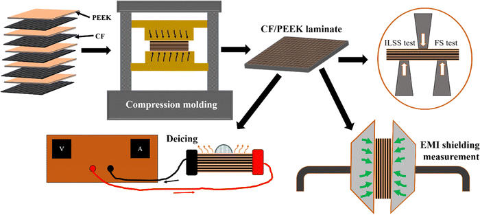
The CF was kept in acetone at room temperature for 48 h to remove the precoated epoxy sizing agent followed by drying for 2 h at 60 °C in a hot air oven. 10 layers of CF and 11 layers of PEEK film having dimensions of 10 × 10 cm2 were consolidated as alternate layers into a mold cavity. The mold was kept in a compression molding machine for heating up to the processing temperature at zero pressure. The mold was given a preheating of 45 min followed by 10 breathing cycles at 0.5 MPa to eliminate air voids in the laminate prior to beginning the molding cycles. The typical processing parameters for the fabrication of CF/PEEK laminates are processing temperature, consolidation pressure, and holding time. The processing temperatures involved in fabrication are 400 °C, 410 °C and 420 °C. The pressure cycle is exerted over the heated mold with the combination of step wise-pressure increment giving each pressure a certain amount of consolidation time. The exerted consecutive pressure steps are 5, 10, 15 and 20 MPa. The step-wise pressure consolidation was performed to ensure proper infusion of PEEK in CF.18 For each pressure step the holding time of 15 min and 30 min was kept ensuring proper infusion of low MFI resin into CF. After the completion of the molding cycle, the mold was allowed to cool at ambient temperature ensuring maximum crystallinity in PEEK. Fig. 1 refers to the fabrication and molding details. The laminate was trimmed and the CF vol% was found to be between 55–60% using ASTM D 3171. The sample code (L1, L2, L3, L4, L5, L6) has been mentioned in Table 1 against the corresponding processing parameter.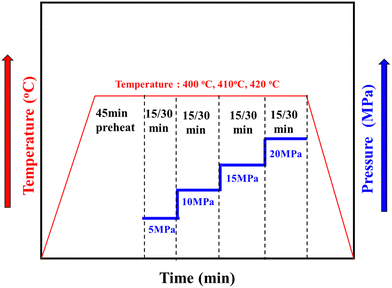 | ||
| Fig. 1 CF/PEEK laminate fabrication steps, testing and characterizations and molding cycle with varying the parameters pressure, temperature and holding time. | ||
| Sample code | Temperature (°C) | Pressure (MPa) | Time (min) |
|---|---|---|---|
| L1 | 400 | 5 + 10 | 15 |
| L2 | 5 + 10 + 15 + 20 | 15 | |
| L3 | 5 + 10 + 15 + 20 | 30 | |
| L4 | 410 | 5 + 10 + 15 + 20 | 30 |
| L5 | 5 + 10 + 15 + 20 | 60 | |
| L6 | 420 | 5 + 10 + 15 + 20 | 30 |
2.3 Characterizations and mechanical testing
Flexural strength was calculated from the equation,
 | (1) |
 | (2) |
 | (3) |
 | (4) |
| A = 1 − R − T | (5) |
3. Results and discussion
3.1 Thermal stability
The DSC heating and cooling curves are shown in Fig. S2(a) (ESI†) of various PEEK/CF laminates studied here. The glass transition temperature (Tg), cold crystallization temperature (Tc) and melting temperature (Tm) of the PEEK matrix are 146 °C, 294 °C and 340 °C, respectively. Therefore, the onset processing temperature was decided based on the general thumb rule of 400 °C and varying by 10 °C to optimize the parameters. The TGA (Fig. S2(b), ESI†) shows that the PEEK is thermally stable up to 520 °C which allows us to safely vary the temperatures between 400–420 °C.3.2 Temperature dependent viscosity profile
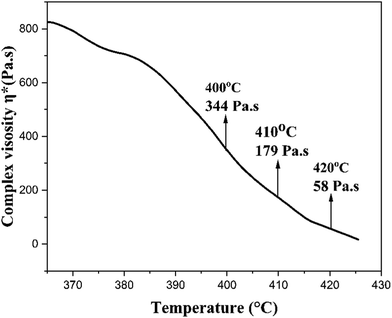
Fig. 3 shows the variation of complex viscosity (η*) for PEEK with respect to temperature. The magnitude of η* decreases on increasing the temperature due to increasing free volume and depletion of secondary interactions between polymer chains, thereby increasing the chain mobility. The η* value of 344 Pa s at 400 °C decreased to 179 Pa s at 410 °C which further dropped to 58 Pa s at 420 °C. The lower value of η* ensures efficient wetting of CF, thereby increasing interfacial bonding between PEEK and CF. However, a very low magnitude of η* becomes detrimental to the laminate, which is discussed in detail in the upcoming sections.3.3 Microstructural characterization of laminates
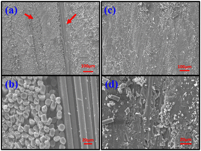
Fig. 4 shows the SEM cross-sectional images of laminates L1 and L2 depicting the effect of increasing pressure cycle on the infusion of PEEK into CF mat. Fig. 4a and b depict the cross-sectional images of sample L1 and it can be seen that there is clear separation between the CF layers and PEEK film, which has not infused into the CF layers (Fig. 4a). The bare carbon fibers without any PEEK depositions in Fig. 4b clearly show that the low-pressure cycle of 5 + 10 MPa for 15 min each at 400 °C is not sufficient for PEEK impregnation into CF layers. On the other hand, when the pressure was increased to 5 + 10 + 15 + 20 MPa, the PEEK can be seen infusing into the CF layers and the PEEK and CF layers become indistinguishable in Fig. 4c, and CF coated with PEEK can be clearly seen in Fig. 4d for the L2 laminate. That is why for all the subsequent laminates the pressure cycle of 5 + 10 + 15 + 20 MPa was used.3.4 Process dependent interfacial strengthening
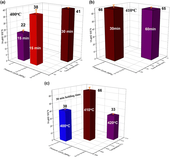
ILSS is one of the important mechanical properties that reflects the nature of the interface in any laminate that is associated with bonding between the layers arising from the evolving microstructure. The ILSS is majorly governed by the effective infusion of the matrix into the fibers at the microscopic scale and hence, understanding the process controlled interfacial strengthening becomes very crucial. We varied the pressure cycle and the holding time at a given temperature and in addition varied only the holding time at a fixed pressure cycle and temperature. The rheological response of any thermoplastic is strongly dominated by temperature and shear. The squeeze flow deformation (experienced in compression molding) controls the matrix wetting and needs to be considered as an additional design parameter here. Our results begin to suggest that a pressure cycle at different holding times is more beneficial than a single cycle as it helps in a more efficient diffusion of PEEK through the CF layers. Fig. 5 shows variation in ILSS of various CF/PEEK laminates fabricated here following a particular pressure cycle at a fixed temperature and holding time.At a given processing temperature of 400 °C, the variation in pressure cycle and holding time was varied (Fig. 5a). The ILSS increased from 22 to 38 MPa when the pressure cycle changed from 5 + 10 MPa to 5 + 10 + 15 + 20 MPa at a given holding time (15 min) for each pressure cycle. This begins to suggest that PEEK infuses well through the CF layers when a longer pressure cycle was followed as it improves the interfacial adhesion in PEEK/CF laminates. In addition, for a particular pressure cycle (5 + 10 + 15 + 20 MPa) when the holding time increases from 15 to 30 min, the ILSS increases from 38 MPa to 41 MPa. By varying the pressure cycle from 5 + 10 MPa to 5 + 10 + 15 + 20 MPa the ILSS improved significantly. Miao et al. have studied the variation in ILSS with respect to applied pressure and observed that ILSS scales with increasing pressure.19 Our results also suggest that the holding time has little role to play here and applied pressure dominates the interfacial strengthening. Based on this observation, we decided to further proceed with 5 + 10 + 15 + 20 MPa. The next challenge is to understand the effect of temperature and hence, we assessed the ILSS at 410 °C (Fig. 5b) keeping the pressure cycle fixed. Interestingly, the ILSS increased to 66.6 MPa for a fixed holding time of 30 min manifesting improved infusion of PEEK into the CF layers. This improvement in ILSS suggests interface strengthening due to better infusion of PEEK into the CF layers which is complemented by the fractography analysis as well, and can be attributed to increment in the flow of PEEK.11,20 When the holding time was further increased to 60 min, the ILSS remained unchanged suggesting that the holding time has little effect to play here and the wetting of PEEK is largely dominated by the pressure cycle adopted and the temperature chosen. Therefore, 30 min of holding time for the chosen pressure cycle was fixed for further optimization. Keeping the pressure cycle (5 + 10 + 15 + 20 MPa) and holding time 30 min fixed (Fig. 5c), we increased the processing temperature further to 420 °C. To our surprise, the ILSS reduced to 33 MPa, which begins to suggest that as the temperature increases the viscosity of the PEEK further drops and instead of wetting the CF layers, it squeezes out. This was in line with the result mentioned in the η* vs. temperature plot (Fig. 3) in which the viscosity dropped by an order of one. The bare CF surface in the fractography images further strengthens our hypothesis that temperatures >420 °C are not suitable to process the laminates. The significant reduction in ILSS at 420 °C can be attributed to reduction of the amount of PEEK in the laminate and PEEK deficient areas and thereby poor load transfer between fibers. We observed more flash during the compression molding process for PEEK/CF laminates when processed at 420 °C and this particular sample resulted in poor adhesion of PEEK onto CF. Based on our understanding, sample L4 showed the best ILSS properties due to the improved interface. The representative plot of load vs. displacement for sample L4 can be seen in Fig. S3 (ESI†).
The in-plane properties of CF/PEEK laminates can be accessed by flexural measurements. The failure mechanism here is majorly dominated by matrix failure and the extent of the bonding of the matrix with the fibers. The FS values show the same trend as observed for ILSS values in Table 2. At 400 °C, on increasing the pressure from 5 + 10 MPa cycle to 5 + 10 + 15 + 20 MPa cycle at 15 minutes holding time, an increment in FS value from 283 MPa for L1 to 409 MPa for L2 laminate is observed. On further increasing the holding time from 15 to 30 minutes a significant improvement to 552 MPa for the L3 laminate is observed. Increasing the processing temperature from 400 °C to 410 °C with the optimized holding time of 30 minutes and 5 + 10 + 15 + 20 MPa pressure cycle increases the FS value from 409 MPa for L3 to 658 MPa for L4 laminate. Increasing the holding time to 60 minutes at 410 °C and the optimized pressure cycle does not yield any improvement in FS value for L5. Again, increasing the processing temperature to 420 °C results in a significant reduction in FS value to 404 MPa for the L6 laminate. This analysis explains the same trend and holds good for FS too. The FS values with respect to each parameter can be seen in Fig. S4 (ESI†).
| Sample code | ILSS (MPa) | Flexural strength (MPa) |
|---|---|---|
| L1 | 22 ± 1.8 | 283.6 ± 16 |
| L2 | 38 ± 3.3 | 409 ± 19 |
| L3 | 41 ± 0.7 | 552 ± 20 |
| L4 | 66.6 ± 3.7 | 658 ± 10 |
| L5 | 65 ± 2.3 | 647 ± 20 |
| L6 | 33 ± 1.6 | 404 ± 18 |
Our results suggest that the obtained mechanical properties of our unmodified CF/PEEK laminates are much superior to those published earlier21–26 where ILSS ranges from 40 to 55 MPa and FS ranges from 300 to 485 MPa. The trend emerging in the mechanical properties with the variation in temperature on the mechanical properties is further examined by fractography.
3.5 Fractography and the interface
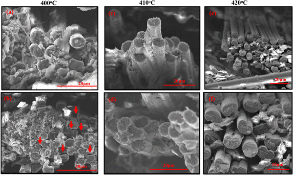
To further strengthen our hypothesis, fractography was assessed in the CF/PEEK laminates. Fig. 6 depicts the SEM fractography images of fractured FS samples fabricated at 400 °C, 410 °C and 420 °C consolidated at 5 + 10 + 15 + 20 MPa for 30 min at each pressure cycle.It can be clearly seen from Fig. 6 that for the samples prepared at 400 °C, there are regions where delamination voids can be seen (Fig. 6a and b). This is also manifested in poor mechanical properties. On the other hand, the samples prepared at 410 °C (Fig. 6c and d) show bundles of perfectly bonded CFs in the PEEK matrix. The perfect bonding between CFs leads to efficient stress transfer between the fibers, thereby improving the mechanical properties. In the case of samples prepared at 420 °C (Fig. 6e and f), the bare fibers without any matrix adhered to it can be clearly seen leading to poor mechanical properties. The fractography is in line with the discussion of the mechanical properties.
3.6 EMI shielding and the de-icing properties
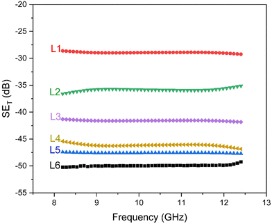
An important property for a material to qualify for aerostructures is EMI shielding. Table 3 depicts the total shielding effectiveness (SET) along with the reflection and absorption component for the various samples studied here. Though the major contributor of EMI shielding in the CF/PEEK laminate is CF, it is important to study the effect of PEEK and its bonding with CF on the shielding properties of the laminates.| Sample code | SET (dB) | A | R | T |
|---|---|---|---|---|
| L1 | −29 | 0.83 | 0.16 | 0.01 |
| L2 | −36 | 0.75 | 0.24 | 0.01 |
| L3 | −41 | 0.86 | 0.13 | 0.01 |
| L4 | −47.5 | 0.97 | 0.02 | 0.01 |
| L5 | -46 | 0.96 | 0.03 | 0.01 |
| L6 | −50 | 0.92 | 0.07 | 0.01 |
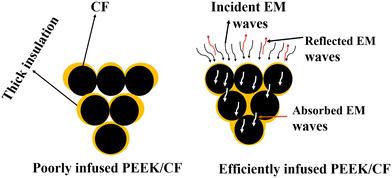
Fig. 7 suggests that the samples that showed good ILSS also showed higher shielding effectiveness (SET). Samples with lower ILSS values (L1, L2, L3, L6) also showed poor EMI shielding properties (SET); however, samples (L4 and L5) that showed excellent ILSS values show higher SET (Table 3). The lower SET values can be attributed to insulating PEEK adhering to CF thereby impeding the conducting pathway. As the PEEK begins to infuse into CF, the uniform distribution of PEEK throughout the laminate created a thin dielectric layer between CF leading to conduction and dielectric losses of EM waves increasing the SET. For sample L6 the SET value is found to be higher than L5 though the ILSS significantly decreased. The higher shielding values can be attributed to high contact between the carbon fibers due to the lack of matrix in L6 leading to higher conduction losses. It is important to mention here that in all the samples ‘A’ was higher than ‘R’ indicating that the dominant mechanism of shielding is by absorption. The mechanism of EMI shielding is illustrated in Fig. 8. The EM waves are guided by the network of CF into the laminate allowing them to penetrate deep inside causing electronic polarization causing attenuation of EM waves. Also, the multiple interfaces between PEEK and CF results in interface polarization, which also helps in additional attenuation of EM waves. The use of liquid metals in the polymer composites showed high shielding values up to 90 dB.27–29 The use of fillers such as Mxenes30 and Ni plating31 and graphene sheets32 over CF were also studied in the past to improve the shielding effectiveness of the CF/PEEK laminates however, our results indicate that the process induced microstructure dominates both the structural as well as functional properties. It is important to note that the SET values of our CF/PEEK laminates show higher EMI shielding performance without any modifications or addition of external materials.
3.7 AC conductivity of CF/PEEK laminates
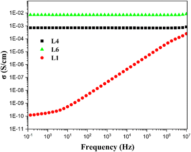
Fig. 9 shows the AC conductivity plots for samples L1, L4 and L6. These samples were chosen based on their mechanical property, which is strongly related to wetting of PEEK over CF. The conductivity values of L4 (0.001 S cm−1) and L6 (0.007 S cm−1) are seven orders of magnitude higher than sample L1 (10−9 S cm−1). The insulating PEEK layer in sample L1 impedes charge transport between CF layers due to the insufficient temperature and pressure cycle adopted during the fabrication process. This particular sample also showed poor mechanical properties as discussed in the manuscript. On the other hand, samples L4 and L6 (where higher temperature and pressure cycles were adopted) showed higher AC conductivity due to minimum matrix between the CF leading to efficient electron tunneling/hopping. This is further supported by the fact that both L4 and L6 showed higher CF volume fraction than L1.3.8 Deicing properties by Joule's heating method
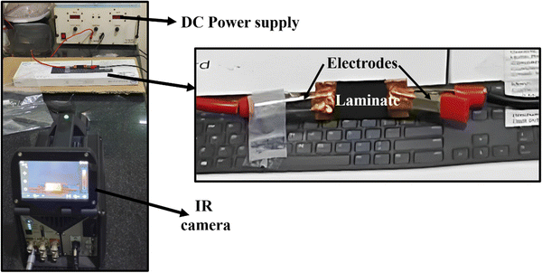
Fig. 10 shows the temperature vs. time curve and the corresponding IR images taken at different intervals of time for the L4 laminate. The IR images clearly show that the rate of heating in L4 is significantly high due to resistive Joule heating. The temperature increased from 40 °C to 90 °C in 3 minutes. The faster heating provides an additional advantage for deicing application in aerostructural parts and is comparable to the currently used CFRE laminates. It is worth noting that the rapid increase in temperature was achieved at a low voltage of 4 V, and 6 W power input. Apart from heating, the heat dissipation rate is also significantly high. The time duration to reach 45 °C from 90 °C is 2 minutes, which is also comparable to the currently used CFRE laminates.16 This gives an additional advantage to CF/PEEK laminates for near engine applications, as discussed in the introduction section.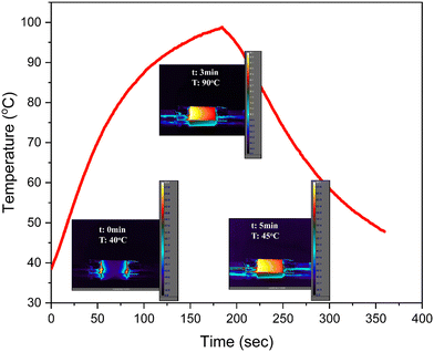 | ||
| Fig. 10 Temperature vs. time plot during Joule's heating along with IR thermal imaging of the L4 laminate. | ||
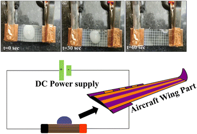
The deicing properties of the optimized CF/PEEK laminate were studied by placing a drop of water and freezing the laminate using liquid N2. The ice starts melting after 30 s (Fig. 11) and the complete disappearance of ice can be seen after 60 s of voltage application, proving it to be a suitable material for deicing application.
The above discussion shows that the additional fast heating, fast heat dissipation and fast deicing characteristics make CF/PEEK laminates a potential candidate for aerostructures.
3.9 Recyclability of CF/PEEK laminate
In order to assess the recyclability of the designed laminates, the CF/PEEK laminate was immersed in 4-chlorophenol solvent to dissolve PEEK. Post 2 h, PEEK was completely dissolved in the solvent leaving behind CF. The PEEK solution was then precipitated using ice cold DI water and the recovered PEEK was dried in a hot air oven. The PEEK was again remolded to make a few samples. This clearly demonstrates that the thermoplastic laminates offer closed-loop circularity in comparison to traditional thermoset composites/laminates (Fig. S1, ESI†). In addition, the PEEK/CF laminates exhibited superior mechanical properties, thereby making them potential candidates for aerostructures.4. Conclusion
In this work, CF/PEEK laminates were fabricated using compression molding. The associated parameters holding time, temperature and pressure cycles were optimized to obtain a high strength laminate with airworthiness. The optimization of the processing temperature suggests that at lower temperature of molding (400 °C), the resin does not get enough translation energy to flow and infuse between the layers of CF hence leading to poor wetting of CF and lower mechanical properties. Also, at higher temperatures (420 °C), too much resin is lost as flash material under high pressure during the molding process and the laminate is deprived of sufficient PEEK matrix, hence reducing the mechanical properties. The optimized processing temperature (410 °C) with correct vol% of matrix in the system provided the best mechanical properties. The optimization of the pressure suggested that the lower pressure cycles were not sufficient to make the PEEK flow and impregnate the CF layers leading to poor wetting of CF and inferior mechanical properties. The high-pressure cycles (5 + 10 + 15 + 20 MPa) lead to an optimized and sufficient pressure enabling PEEK to infuse properly in CF leading to superior mechanical properties. Also, the optimization of holding time showed that 15 min of holding time for each pressure cycle is not sufficient to reach the required mechanical strength and 60 min does not have significant effects on the mechanical properties; therefore, 30 min of holding time for each pressure cycle was optimized for the maximum achievable mechanical properties. The optimized sample shows an ILSS value of 66 MPa and FS of 658 MPa qualifying as airworthy material. The EMI shielding measurements showed that the impregnation of PEEK into CF has a significant effect on the SET values of the CF/PEEK laminates. Samples with good impregnation and higher mechanical strength show higher shielding values. The optimized sample shows SET up to −47.5 dB. The optimized CF/PEEK laminate was also tested for deicing application using the Joule heating method. The test showed that the time interval of 30 s is sufficient for melting the ice frozen over the CF/PEEK laminate. The above conclusions suggest that the CF/PEEK laminate fabricated in this work possesses the required mechanical, EMI shielding and deicing properties making it a potential candidate for aerostructural materials. Though there are still the challenges of high material cost and lack of research facility, the potency of CF/PEEK laminates as a structural material in the aerospace sector will overcome this challenge with more R & D and scientific advances.Conflicts of interest
There are no conflicts to declare.Acknowledgements
Among the authors, SB and SK are grateful to SERB for the generous funding, and RR is grateful to AFMM, IISc for microscopy imaging and MoE, Government of India for the Prime Minister's Research Fellowship (PMRF).References
- S. Pantelakis and K. Tserpes, Revolutionizing Aircraft Materials and Processes, 2020.
- S. Rana and R. Fangueiro, Advanced Composite Materials for Aerospace Engineering, Woodhead, 2016 Search PubMed.
- S. Black, CompositesWorld, 2016, 1–5 Search PubMed.
- S. Black, High-Performance Compos., 2015, 2015, 1–6 Search PubMed.
- J. Weber and J. Schlimbach, Adv. Manuf. Polym. Compos. Sci., 2019, 5, 172–183 CAS.
- A. J. Comer, D. Ray, W. O. Obande, D. Jones, J. Lyons, I. Rosca, R. M. O’Higgins and M. A. McCarthy, Compos. Part A Appl. Sci. Manuf., 2015, 69, 10–20 CrossRef CAS.
- D. Mathijsen, Reinf. Plast., 2015, 59, 185–189 CrossRef.
- C. Red, Compositeworld, 2014, 1–6 Search PubMed.
- P. Davies, H. H. Kausch, J. G. Williams, A. J. Kinloch, M. N. Charalambides, A. Pavan, D. R. Moore, R. Prediger, I. Robinson, N. Burgoyne, K. Friedrich, H. Wittich, C. A. Rebelo, A. Torres Marques, F. Ramsteiner, B. Melve, M. Fischer, N. Roux, D. Martin, P. Czarnocki, D. Neville, I. Verpoest, B. Goffaux, R. Lee, K. Walls, N. Trigwell, I. K. Partridge, J. Jaussaud, S. Andersen, Y. Giraud, G. Hale and G. McGrath, Compos. Sci. Technol., 1992, 43, 129–136 CrossRef CAS.
- A. J. Smiley and R. B. Pipes, Compos. Sci. Technol., 1987, 29, 1–15 CrossRef CAS.
- K. Fujihara, Z. M. Huang, S. Ramakrishna and H. Hamada, Compos. Sci. Technol., 2004, 64, 2525–2534 CrossRef CAS.
- B. Zheng, M. Li, T. Deng, H. Zhou, Z. Huang, H. Zhou and D. Li, Polym. Compos., 2019, 40, 3823–3834 CrossRef CAS.
- E. Mikinka and M. Siwak, J. Mater. Sci.: Mater. Electron., 2021, 32, 24585–24643 CrossRef CAS.
- S. Parasuram, P. Banerjee, R. Raj, S. Kumar and S. Bose, ACS Appl. Mater. Interfaces, 2023, 15(23), 28581–28593 CrossRef CAS.
- S. K. Singh, K. Sushmita, D. Sharma, Y. O. Waidi and S. Bose, Carbon N. Y., 2023, 209, 118036 CrossRef CAS.
- S. H. Jang and Y. L. Park, Nanomater. Nanotechnol., 2018, 8, 1–8 Search PubMed.
- J. Seyyed Monfared Zanjani, B. Saner Okan, P. N. Pappas, C. Galiotis, Y. Z. Menceloglu and M. Yildiz, Compos. Part A Appl. Sci. Manuf., 2018, 106, 1–10 CrossRef CAS.
- A. Flores, S. Quiles-Díaz, P. Enrique-Jimenez, A. Martínez-Gómez, M. A. Gómez-Fatou and H. J. Salavagione, Polymers, 2021, 13(15), 2440 CrossRef CAS PubMed.
- Q. Miao, Z. Dai, G. Ma, F. Niu and D. Wu, Compos. Struct., 2021, 266, 113779 CrossRef CAS.
- P. Y. B. Jar, R. Mulone, P. Davies and H. H. Kausch, Compos. Sci. Technol., 1993, 46, 7–19 CrossRef CAS.
- H. Lyu, N. Jiang, J. Hu, Y. Li, N. Zhou and D. Zhang, Compos. Sci. Technol., 2022, 217, 109096 CrossRef CAS.
- E. A. M. Hassan, D. Ge, L. Yang, J. Zhou, M. Liu, M. Yu and S. Zhu, Compos. Part A Appl. Sci. Manuf., 2018, 112, 155–160 CrossRef CAS.
- E. A. M. Hassan, T. H. H. Elagib, H. Memon, M. Yu and S. Zhu, Materials, 2019, 12(5), 778 CrossRef CAS PubMed.
- C. Yuan, D. Li, X. Yuan, L. Liu and Y. Huang, Compos. Sci. Technol., 2021, 201, 108490 CrossRef CAS.
- E. A. M. Hassan, L. Yang, T. H. H. Elagib, D. Ge, X. Lv, J. Zhou, M. Yu and S. Zhu, Compos. Part B Eng., 2019, 171, 70–77 CrossRef CAS.
- H. Lyu, N. Jiang, Y. Li and D. Zhang, Compos. Sci. Technol., 2021, 210, 108831 CrossRef CAS.
- F. W. Huang, Q. C. Yang, L. C. Jia, D. X. Yan and Z. M. Li, Chem. Eng. J., 2021, 426, 131288 CrossRef CAS.
- L. C. Jia, X. X. Jia, W. J. Sun, Y. P. Zhang, L. Xu, D. X. Yan, H. J. Su and Z. M. Li, ACS Appl. Mater. Interfaces, 2020, 12, 53230–53238 CrossRef CAS PubMed.
- S. Q. Yi, H. Sun, Y. F. Jin, K. K. Zou, J. Li, L. C. Jia, D. X. Yan and Z. M. Li, Compos. Part B Eng., 2022, 239, 109961 CrossRef.
- X. Yuan, J. Jiang, H. Wei, C. Yuan, M. Wang, D. Zhang, L. Liu, Y. Huang, G. L. Gao and Z. Jiang, Compos. Sci. Technol., 2021, 201, 108496 CrossRef CAS.
- S. Li, Y. Jin, Z. Wang, Q. He, R. Chen, J. Wang, H. Wu, X. Zhao and J. Mu, Colloid Polym. Sci., 2019, 297, 967–977 CrossRef CAS.
- Y. K. Li, P. Y. Du, Z. X. Wang, H. D. Huang and L. C. Jia, Compos. Part A Appl. Sci. Manuf., 2022, 160, 107063 CrossRef CAS.
Footnote |
| † Electronic supplementary information (ESI) available. See DOI: https://doi.org/10.1039/d3ma00318c |
| This journal is © The Royal Society of Chemistry 2023 |

