
 Open Access Article
 This Open Access Article is licensed under a
 Creative Commons Attribution 3.0 Unported Licence
Hierarchical porous-structured self-standing carbon nanotube electrode for high-power lithium–oxygen batteries†
Jittraporn
Saengkaew
a,
Takashi
Kameda
ab and
Shoichi
Matsuda
 *ab
*ab
aCenter for Green Research on Energy and Environmental Materials, National Institute for Material Science, 1-1 Namiki, Tsukuba, Ibaraki 305-0044, Japan. E-mail: matsuda.shoichi@nims.go.jp
bNIMS-SoftBank Advanced Technologies Development Center, National Institute for Material Science, 1-1 Namiki, Tsukuba, Ibaraki 305-0044, Japan
First published on 30th August 2023
Abstract
The demand for energy storage devices with high energy and power densities has increased, and lithium–oxygen batteries (LOBs) have attracted significant attention owing to their superior theoretical energy density, which exceeds that of conventional lithium-ion batteries. Although recently reported LOBs exhibit cell-level energy densities greater than 500 W h kg−1, their power densities are less than 1.0 mW cm−2, limiting their widespread use as energy storage devices. In this study, we fabricated a carbon nanotube (CNT)-based self-standing membrane with macro-sized interconnected pores using a nonsolvent-induced phase separation technique and demonstrated its practical application as the positive electrode in high-power-density LOBs. In particular, LOBs equipped with the prepared CNT electrode exhibited power densities greater than 4.0 mW cm−2, which is the highest performance reported thus far. These results demonstrate the feasible practical implementation of CNT-based membrane electrodes in LOBs with high energy and power densities.
Introduction
In recent years, the demand for energy storage devices with high energy and power densities has increased owing to the high demand for electric vehicles and electronic devices. Conventional lithium-ion batteries (LiBs) are among the most widely used rechargeable batteries; however, their performance has reached the theoretical limit. Thus, the development of new types of rechargeable batteries is critical. In particular, lithium–oxygen batteries (LOBs), which use atmospheric oxygen and lithium metal as the active materials for the positive and negative electrode reactions, respectively, have attracted considerable attention owing to their extremely high theoretical energy density.1,2 Although recent studies successfully demonstrated LOBs with cell-level energy densities greater than 500 W h kg−1, their power densities were less than 0.5 mW cm−2,3 limiting their widespread use as energy storage devices.Typical LOBs consist of a lithium metal foil, separator, lithium-ion-conducting nonaqueous electrolyte, porous carbon electrode, and gas-diffusion layer. On the positive electrode side, atmospheric oxygen dissolves in the electrolyte and an oxygen reduction reaction proceeds during the discharging process, forming Li2O2 as the discharge product. The formed Li2O2 accumulates in the pores of the carbon electrodes. During the charging process, the Li2O2 is electrochemically decomposed, and the resulting oxygen is released into the atmosphere. On the negative electrode side, the lithium foil dissolves during the discharging process, whereas during the charging process, lithium is electrochemically deposited. To obtain LOBs with superior power densities, the poor reaction kinetics at the positive oxygen electrode should be addressed. Because the concentration of dissolved oxygen in a nonaqueous electrolyte is significantly lower than that in an aqueous electrolyte, the porous carbon electrode should possess a high surface area to improve the effective electrochemical surface area. Various types of carbon nanomaterials, including carbon black,4–6 graphene,7 and carbon nanotubes (CNTs),8–10 have been investigated as the positive electrodes in LOBs. Among them, CNTs are a promising material owing to their superior characteristics, such as high surface area, electrical conductivity, and stability. In addition, they can be used to prepare a self-standing membrane using methods such as simple vacuum filtration. Although, many studies have demonstrated the superior performance of LOBs equipped with CNT-based positive electrodes,8–10 they have primarily focused on evaluating the CNT-based electrode at the material level, with only a few studies evaluating the performance of LOBs under practical conditions using appropriate technological parameters. In particular, the ratio of electrolyte weight to cell capacity (E/C; g A−1 h−1), which is an empirical indicator of the electrolyte amount in LiBs, should be maintained below 10 g A−1 h−1 to obtain LOBs with energy densities greater than 300 W h kg−1.11
In addition, LOBs exhibit poor power density. Owing to the limited oxygen solubility in nonaqueous electrolytes, most existing LOBs exhibit operating current densities of less than 0.5 mA cm−2 during the discharging process,11 which are lower than those of conventional LiBs (>2 mA cm−2). From a material design perspective, the positive electrode should contain interconnected macro-sized pores, which may function as oxygen transport channels, to achieve an efficient oxygen supply through the electrode. Therefore, in this study, we investigated techniques to fabricate a self-standing CNT electrode with high porosity and surface area to achieve stable LOB operation under high-power-density conditions. Using a nonsolvent-induced phase separation (NIPS) method, we successfully fabricated a self-standing CNT membrane with a porosity greater than 90% and surface area greater than 140 m2 g−1, which was equivalent to 70% of that of powder-state CNTs. Notably, LOB cells containing this membrane exhibited power densities greater than 4.0 mW cm−2 under lean-electrolyte conditions (E/C < 10 g A−1 h−1). To the best of our knowledge, this is the highest performing LOB reported thus far.
Experimental
Preparation of CNT self-standing membrane
A CNT powder sample was utilized for preparing self-standing CNT membrane. A mixture slurry was prepared using 80 wt% of single walled carbon nanotube (OCSiAl, TUBALL, average fiber diameter of 1.6 nm and average length of 5 μm), and 20 wt% of PAN in NMP. The mixture slurry was formed into a sheet by molding to a uniform thickness by a wet film forming method using a doctor blade. After molding, the sample was immersed in methanol (poor solvent) and converted to a porous film by the non-solvent induced phase separation (NIPS) method. Further, a volatile solvent was removed by drying the sample at 80 °C for 10 h; subsequently heat treatment was performed (infusibilization treatment) at 230 °C for 3 h in the atmosphere using a box-type furnace (Denken High Dental Co., Ltd). Carbonization was performed by raising the temperature to 1050 °C at a rate of 10 °C min−1 and maintaining the temperature of 1050 °C for 3 h in Ar atmosphere with flow rate of 800 mL min−1. Then allowing the sample to cool to room temperature.Characterization of CNT self-standing membrane
Micro-/mesoporous structures of the samples were characterized by nitrogen adsorption (3 FLEX, Micromeritics Instrument Corp.). Macropore size distributions were measured by mercury porosimetry (AutoporeIV 9505, Shimadzu Co.). X-ray diffraction (XRD) patterns of the membranes were conducted on an X-ray diffractometer (SmartLab, Rigaku). The obtained membranes were further examined by Raman scattering spectra on a laser Raman microscope (RamanTouch-VIS-NIR, Nanophoton). Field-emission SEM (FE-SEM, S-4800, Hitachi) was used to characterize the discharge products. Prior to the SEM analyses, the positive electrodes were removed from the electrochemical cells after the discharging process, washed three times with acetonitrile, and dried under vacuum. During sample preparation, the samples were not exposed to ambient atmosphere.Lithium–oxygen cell assembly and discharge performance test
A solution of 1 M lithium bis(trifluoromethanesulfonyl)imide (LiTFSI; Kishida Chemical Co., Ltd, purity >99.9%) dissolved in tetraethylene glycol dimethyl ether (TEGDME; Kishida Chemical Co., Ltd, purity >99%) was used as the electrolyte. The water content of the electrolyte was less than 30 ppm and was measured by Karl Fischer titration. The carbon electrode was dried at 100 °C under vacuum for 12 h. Coin-type lithium–oxygen cells were assembled in a dry room with a water content of less than 10 ppm, by sequential stacking of metallic lithium foil (diameter = 16 mm, thickness = 0.2 mm; Honjo Metal Co., Ltd), a glass fiber-based separator (diameter = 18 mm, thickness = 0.21 mm; Whatman GF-A), a carbon electrode (diameter = 16 mm), and a gas diffusion layer (diameter = 16 mm, thickness = 0.19 mm; TGP-H-060, Toray, Japan). During assembling, 100 μL of the electrolyte was added to the separator. Electrochemical experiments were conducted using a battery-test equipment (SD8, Hokuto Denoko Corp.).Lithium–oxygen cell assembly and discharge/charge performance test
A solution of 0.5 M LiTFSI, 0.5 M LiNO3 (Sigma-Aldrich, purity >99.9%) and 0.2 M LiBr (Sigma-Aldrich, purity >99.9%) dissolved in TEGDME was used as the electrolyte. LiNO3 and LiBr were dried at 120 °C under vacuum before using. The CNT electrode was dried at 100 °C under vacuum for 12 h. Lithium–oxygen cells were assembled in a dry room with a water content of less than 10 ppm, by a sequential stacking of a lithium-metal foil (20 mm square, thicknesses of 0.1 mm; Honjo Metal Co., Ltd), polyolefin-based separator (22 mm square, thickness of 0.02 mm), porous carbon electrode (20 mm square), and gas-diffusion layer. A ceramic-based solid-state separator (LICGC, thickness of 0.50 mm; Ohara, Inc.) was utilized for the protection of the lithium-metal negative electrode. In this case, the ceramic-based solid-state separator was sandwiched by polyolefin-based separators and same kinds of electrolyte were utilized for both positive electrode side and negative electrode side. During assembling, 2.5 μL cm−2 of the electrolyte was added to the separator. A pressure of 100 kPa was applied to the cell by a spring coil. Electrochemical experiments were conducted using a battery-test equipment (TOSCAT, Toyo System Co., Ltd). The limiting capacity and cutoff voltage were set to 4.0 mA h cm−2, 2.0 V/4.5 V. The current density during discharging and charging process was set to 0.4 and 0.2 mA cm−2.Results and discussion
Fig. 1 illustrates the three methods used in this study to fabricate the self-standing CNT membranes, namely the vacuum filtration (VF), doctor blading (DB), and nonsolvent-induced phase separation (NIPS) methods. The physical parameters of the prepared CNT membranes, denoted as VF-CNT, DB-CNT, and NIPS-CNT, are shown in Table 1. The porosity was calculated by weight and thickness of carbon membrane, assuming that the density of membrane is 2.1 g cm−3. CNTs are an ideal material for the positive electrode of LOBs owing to their superior properties; however, during the membrane preparation process, CNTs tend to aggregate, which decreases their surface area. In general, the surface area of CNT membranes is significantly lower than that of powder-state CNTs. Fig. 2a shows the SEM image of the VF-CNT membrane prepared using 0.05 wt% CNT solution dispersed in H2O. The diameters of the structured CNTs in the VF-CNT membrane were in the range of 100–200 nm, which was significantly larger than that of an individual CNT (1.6 nm). Although the CNTs were well dispersed in the precursor solution, they aggregated during the membrane preparation process owing to an increase in the specific CNT concentration during vacuum filtration (Fig. 1). The porosity of the VF-CNT membrane was less than 80%.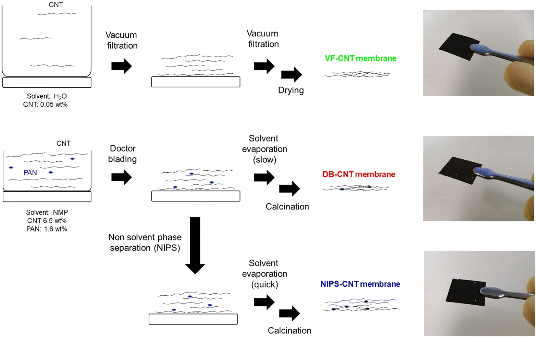 | ||
| Fig. 1 Schematic illustration for synthetic procedures and photographic image for CNT membranes prepared via vacuum-filtration (VF), doctor blading (DB), and nonsolvent-induced phase separation (NIPS) methods. | ||
| Membrane | Mass loading (mg cm−2) | Thickness (μm) | Porosity (%) |
|---|---|---|---|
| VF-CNT | 1.5 | 45 | 76 |
| DB-CNT | 1.5 | 78 | 85 |
| NIPS-CNT | 1.5 | 104 | 91 |
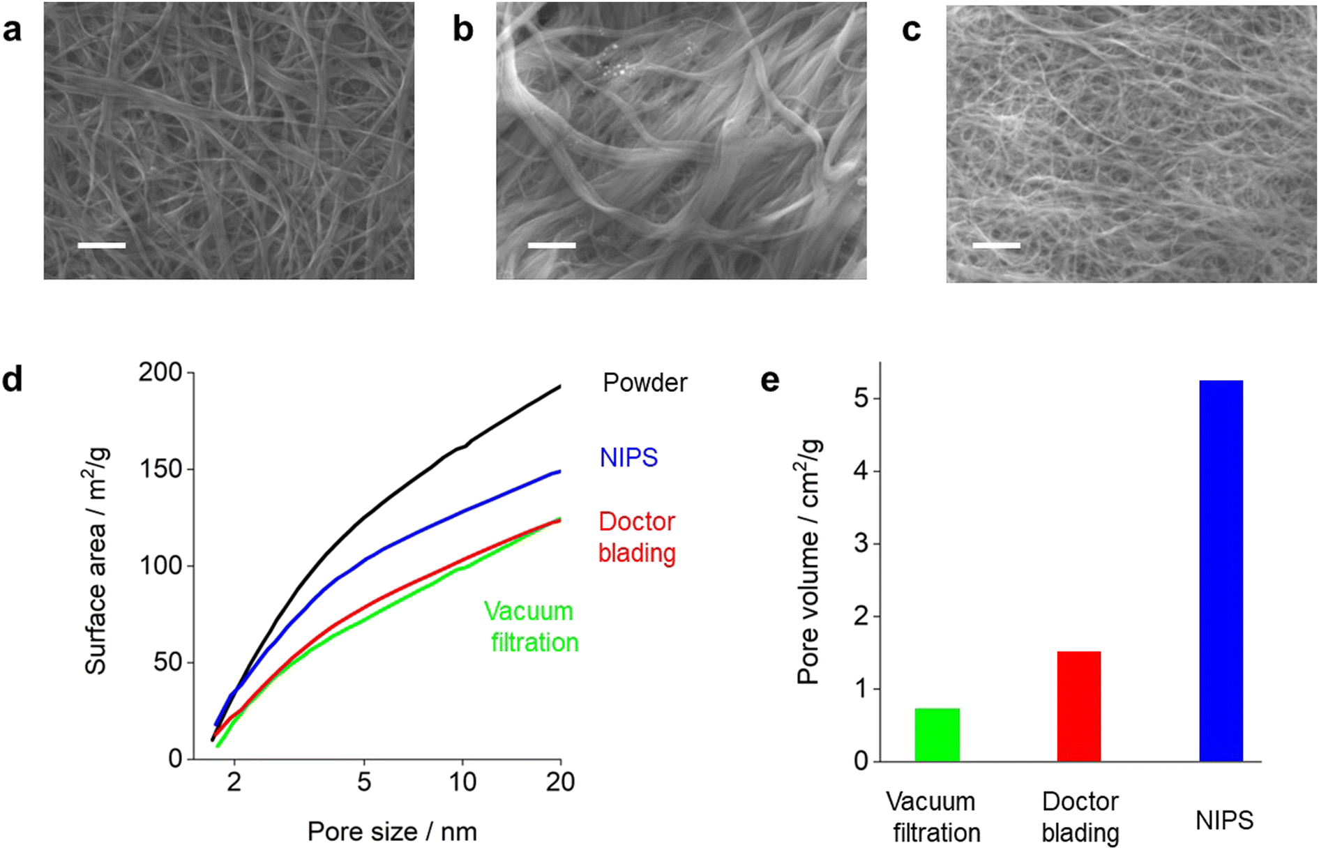 | ||
| Fig. 2 SEM images of the CNT membranes prepared via (a) vacuum filtration, (b) doctor blading, and (c) NIPS. Scale bars are 500 nm. (d) Surface areas of pristine CNT powder and CNT membranes evaluated using the Barrett–Joyner–Halenda (BJH) method. (e) Pore volumes in the region of 0.1–1.0 μm evaluated using Hg intrusion methods. | ||
In addition to the vacuum filtration method, doctor blading is a suitable technique for preparing self-standing CNT membranes. The doctor-blading method requires a slurry with a high viscosity; therefore, we prepared an N-methyl-2-pyrrolidone (NMP)-based slurry containing CNTs with polyacrylonitrile (PAN), which was added to improve the dispersibility of the CNTs in the slurry and was finally converted to carbon through heat treatment under inert conditions. As results, the PAN-based carbon function as binder between CNTs, improving the mechanical strength of membrane. When the PAN ratio is less than 5%, the prepared membrane cannot retain their self-standing nature.
The SEM image of the DB-CNT membrane prepared via the slurry-coating technique is shown in Fig. 2b. The diameters of the CNTs in the DB-CNT membrane were in the range of 100–500 nm. Although some aggregation was observed, the porosity of the DB-CNT membrane was approximately 85%.
In the doctor-blading method, CNT aggregation occurred during the membrane drying process (Fig. 1), resulting in a lower surface area of the DB-CNT membrane compared to that of the pristine CNT powder. Therefore, to prevent the undesired aggregation of the CNTs, we focused on the nonsolvent-induced phase separation technique (NIPS).3,12,13 In the NIPS process, the membrane was formed from a slurry using a doctor blade. The wetted membrane was placed in an ethanol (EtOH) bath and the solvent was exchanged thrice to completely replace the NMP with EtOH. The EtOH in the CNT membrane was then quickly removed via a vacuum evaporation process, minimizing undesired CNT aggregation. During the NIPS process, interconnected hierarchical macroscale pores were formed, which improved the porosity of the prepared NIPS-CNT membrane.
Fig. 2c shows a SEM image of the NIPS-CNT membrane. The diameter of the CNT bundles was approximately 50 nm, which was significantly smaller than those of the VF-CNT and DB-CNT membranes. The porosity of the NIPS-CNT membrane was 91%. In addition, we evaluated the Brunauer–Emmett–Teller (BET) surface areas of the CNT membranes. The apparent BET surface areas (SBET) of the pristine CNT powder and CNT membranes are shown in Fig. 2d. The VF-CNT and DB-CNT membranes exhibited lower SBET values compared with that of pristine CNT powder, indicating that the surface area of the CNT membranes was significantly reduced during the membrane preparation process regardless of the method. In contrast, the SBET value of the NIPS-CNT membrane was greater than 140 m2 g−1, which was equivalent to 70% of that of the powder-state CNTs. Thus, the NIPS technique was clearly effective for fabricating self-standing CNT membranes by suppressing undesired aggregation during the membrane preparation process. Mercury porosimetry was used to evaluate the macro-sized pore volume (0.1–1.0 μm). The pore volumes in the VF-CNT and DB-CNT membranes were less than 1.5 cm2 g−1, whereas that of the NIPS-CNT membrane was greater than 5.0 cm2 g−1.
We then investigated the performance of stacked-type LOB cells equipped with the prepared self-standing CNT membranes as the positive electrodes and evaluated the full-discharge capacities of the electrodes. In the stacked-cell configuration, oxygen is transported horizontally in the gas diffusion layer.14 The oxygen is then transported vertically to permeate the entire positive electrode (Fig. 3a). In contrast, the oxygen in a coin-type LOB cell is supplied from the top part of the electrode (Fig. 3e). The amount of electrolyte injected into the CNT electrode was quantitatively controlled using our recently developed stamping method to uniformly inject the electrolyte into the entire electrode.14 For the separator, a 20 μm thick polyolefin (PO)-based membrane was used.
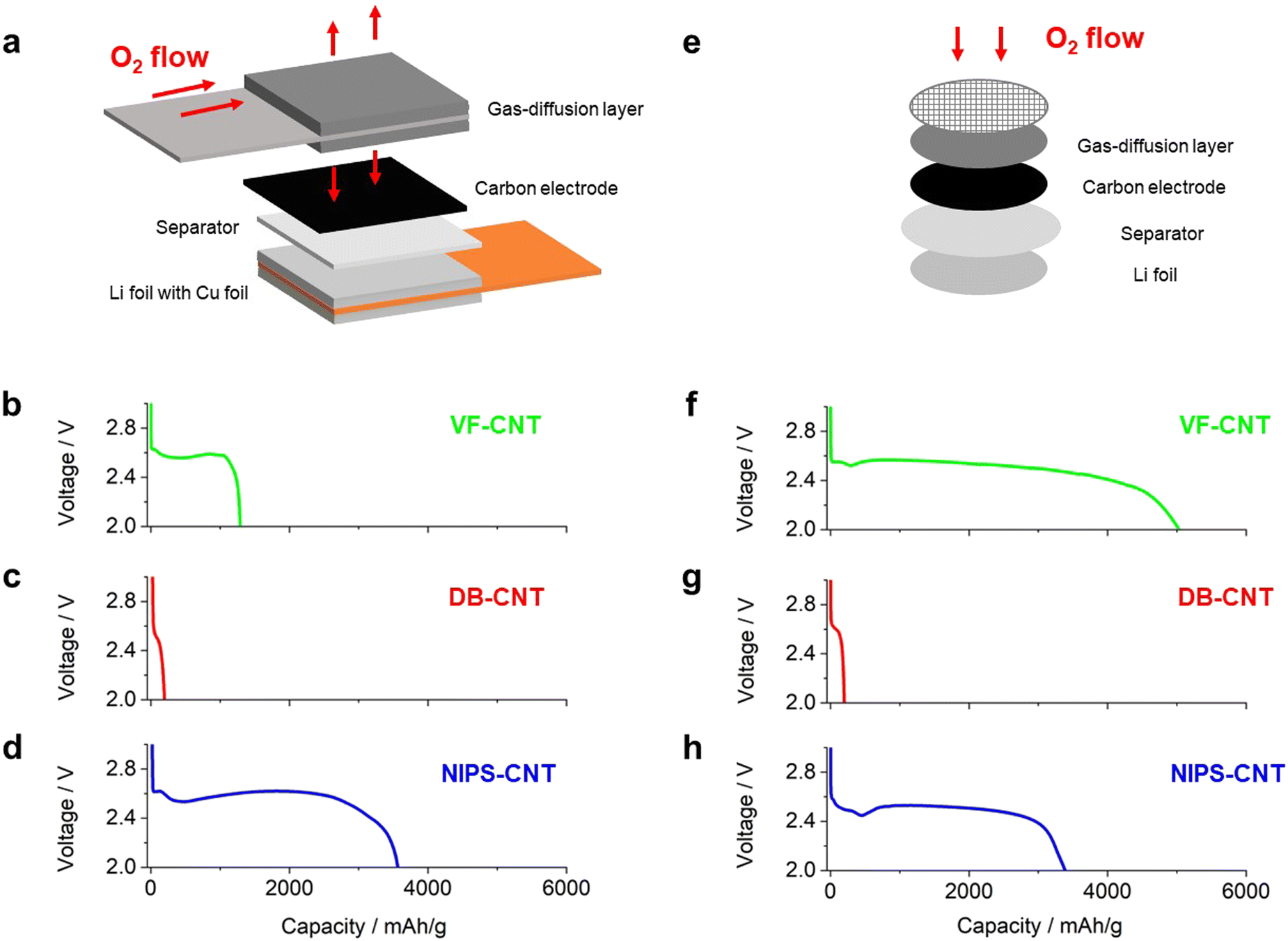 | ||
| Fig. 3 (a) Schematic of a stacked-type LOB cell. (b)–(d) Discharge profiles of stacked-type LOB cells containing CNT electrodes prepared via vacuum filtration (green curve), doctor blading (red curve), and the NIPS method (blue curve) at current densities of 0.4 mA cm−2. (e) Schematic of coin-type LOB cell. (f)–(h) Discharge profiles of coin-type LOB cells containing CNT electrodes prepared via vacuum filtration (green curve), doctor blading (red curve), and the NIPS method (blue curve). | ||
Fig. 3b–d shows the discharge profiles of stacked-type LOB cells equipped with the series of self-standing CNT electrodes at a current density of 0.4 mA cm−2. The VF-CNT cell exhibited a stable voltage plateau of 2.55 V during the discharging process (Fig. 3b). The voltage then gradually decreased, and the cell exhibited a capacity of approximately 1200 mA h g−1 at the cutoff voltage of 2.0 V. In contrast, the DB-CNT cell exhibited a poor discharge capacity of less than 200 mA h g−1 (Fig. 3c). The voltage in the NIPS-CNT cell gradually decreased after the capacity reached 2500 mA h g−1 (Fig. 3d), and this cell exhibited a capacity of 3600 mA h g−1 at the 2.0 V cutoff condition. We then evaluated the discharge capacity of coin-type cells with excess electrolyte using a 200 μm thick glass-fiber-based separator instead of the 20 μm thick PO-based separator used in the stacked-type cells. The coin-type DB-CNT and NIPS-CNT cells exhibited similar discharge capacities to those of the stacked-type LOB cells (Fig. 3g and h). We consider that the poor discharge performance of DB-CNT originated in limited macro sized pore and limited freedom for volume change of electrode.15 In contrast, the coin-type VF-CNT LOB cell exhibited a superior discharge capacity of more than 4000 mA h g−1 (Fig. 3f), which was significantly higher than that of the corresponding stacked-type LOB cell. These results clearly demonstrated that the discharge performance of the VF-CNT was significantly lower in a practical stacked-type cell configuration compared with that in a coin-type cell.
Repeated discharge/charge cycle tests were performed on the LOBs with an electrolyte containing a redox mediator (0.5 M LiTFSI + 0.5 M LiNO3 + 0.2 M LiBr in TEGDME) to achieve high efficiency at both the negative and positive electrodes. To minimize side reactions in the Li-metal negative electrode, a solid-state ceramic-based separator was used to protect the negative electrode. The mass loading of the CNT electrode was approximately 3.0 mg cm−2. The amount of electrolyte in the cell was 16 μL cm−2, and its areal capacity was set at 2 mA h cm−2. Consequently, the E/C value of the LOB cells was 8.8 g A−1 h−1.
Fig. 4a and b show the discharge/charge profile of the LOB cells equipped with the VF-CNT and NIPS-CNT as the positive electrodes. For this experiment, the current density was set to 0.2 mA cm−2 during both the discharging and charging processes. The VF-CNT cell exhibited a stable voltage plateau of approximately 2.6 V during the first discharging process (black curve in Fig. 4a). During the charging process, the voltage gradually increased from 3.0 to 3.6 V, and the cell exhibited a stable plateau region of 3.6 V; this is a typical charging profile for this electrolyte.12 As the charging process progressed, the voltage gradually increased to reach a charging voltage of 4.2 V. In contrast, during the 10th cycle, the voltage profile was unstable during both the discharging and charging processes. During the discharging process, a voltage fluctuation was observed (green curve in Fig. 4a). In addition, during the charging process, the voltage sharply increased up to the 4.2 V cutoff condition. This phenomenon has been observed in previous studies and is considered typical in lean electrolyte LOBs.14 In the NIPS-CNT cell, the voltage profile during the first discharge/charge cycle (black curve in Fig. 4b) was similar to that of the VF-CNT cell. Although the over-potential gradually increased during both the discharging and charging processes in the repeated cycles, the cell exhibited a stable voltage profile up to the 10th and 20th cycles (green and red curves, respectively, in Fig. 4b). However, during the 30th cycle, the charge voltage reached the 4.2 V cutoff at a capacity of less than 1.0 mA h cm−2. These results indicate that, for a stable LOB operation under lean-electrolyte conditions with a stacked-cell configuration, the performance of the NIPS-CNT cell was superior to that of the VF-CNT cell.
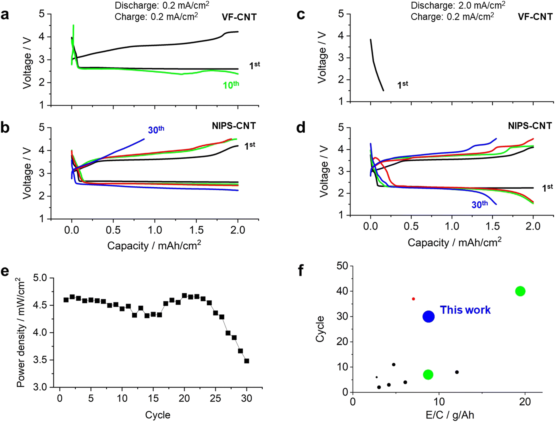 | ||
| Fig. 4 Discharge/charge profiles of LOB cells containing CNT electrodes prepared via (a) and (c) vacuum filtration and (b) and (d) the NIPS method. 1st cycle: black curves, 10th cycle: green curves, 20th cycle: red curves, and 30th cycle: blue curves. (e) Plot of power density versus cycle number in NIPS-CNT LOB cells operated at current densities of 2.0 and 0.2 mA cm−2 during the discharging and charging processes, respectively. (f) Comparison of the cycle life versus E/C for previously reported LOBs and the NIPS-CNT LOB reported in this study. The size of the plot points represents the magnitude of the power density. Red plot: ref. 3, green plots: ref. 17, black plots: ref. 15 and ref. 16. | ||
In addition, the cells were cycled under high-power operating conditions of the 2.0 mA cm−2 and 0.2 mA cm−2 current densities during the discharge and charge processes, respectively. Under these conditions, the discharge voltage in the VF-CNT cell dropped sharply and reached the cutoff voltage of 2.0 V (Fig. 4c). In contrast, the NIPS-CNT cell exhibited a stable voltage plateau at approximately 2.3 V even under high-current-density conditions (black curve in Fig. 4d). The voltage profiles during the discharging and charging processes were similar; however, as the number of cycles increased, the over-potential increased in both the discharging and charging processes. Although the final voltage in the discharging process decreased to 1.5 V in the 10th cycle, the capacity reached the limitation condition of 2.0 mA h cm−2 (green curve in Fig. 4d). After the 20th cycle, the capacity gradually decreased and reached 1.5 mA h cm−2 in the 30th cycle (red and blue curves, respectively, in Fig. 4d). The power density of the NIPS-CNT cell was plotted against the cycle number (Fig. 4e), revealing that the cell exhibited a power density greater than 4.5 mW cm−2 up to the 25th cycle. After the 25th cycle, the power density gradually decreased, which is considered to be originated from accumulation of solid-state side products and/or shortage of electrolyte.16–18 The coulombic efficiency and round trip efficiency were over 95% and 60% through the cycle (Fig. S1 and S2, ESI†).
To further our understanding of the discharge/charge reaction in the NIPS-CNT LOB, we performed X-ray diffraction (XRD) analysis on the electrode. Fig. S3 (ESI†) shows the XRD spectra of the NIPS-CNT electrode after undergoing a discharge or charge reaction with a capacity limitation of 2 mA h cm−2 and discharge/charge current density of 2.0/0.2 mA cm−2. In the XRD spectra of the electrodes removed from the LOB cell after the first discharging process, a clear peak corresponding to Li2O2 was observed. In contrast, these peaks disappeared from the spectra of the electrodes after the first charging process. In addition, scanning electron microscopy (SEM) analysis was performed on the electrodes (Fig. S4, ESI†). The SEM images of the electrodes removed from the LOB cell after the first discharging process exhibited a uniform distribution of solid-state products on the surface of the CNTs. In the image of the electrode after the charging process, these products had disappeared from the electrode. The XRD and SEM results suggest that an ideal discharge reaction proceeded even when the LOBs were operated under high-power-density conditions.
Table S1 (ESI†) summarizes the performance of LOBs reported in the literature, including technological and battery performance parameters such as the areal capacity, electrolyte amount, current density, power density, and cycle life.19–21 To estimate the performance of practical LOBs, the cycle life was plotted against the E/C (Fig. 4f); the size of the plot points represents the magnitude of the power density. To obtain LOBs with energy densities greater than 300 W h kg−1, the E/C value should be less than 10 g A−1 h−1. Notably, the LOBs in this study exhibited the highest performance in terms of a long cycle life and high-power density with an E/C value of less than 10 g A−1 h−1. These results clearly demonstrate the superior performance of the hierarchical porous-structured CNT electrodes prepared using the NIPS technique to fabricate LOBs with a high-power density and long cycle life.
Conclusions
We prepared a self-standing CNT membrane via the NIPS technique. Notably, the high surface area and pore volume of the prepared CNT membrane was similar to those of powder-state CNTs; this was achieved by suppressing the aggregation of the CNTs during the membrane preparation process. The performance of LOB cells equipped with the prepared CNT membrane as the positive electrode was evaluated. The LOB cell exhibited a stable voltage profile during repeated discharge/charge cycles, demonstrating a power density greater than 4 mW cm−2. To the best of our knowledge, this is the highest performance among existing nonaqueous LOBs under lean-electrolyte and high-areal-capacity conditions. This superior discharge performance was attributed to the high surface area and interconnected macro-sized pores that functioned as oxygen transport channels through the electrodes. We believe that the results of this study provide a new research direction for the practical implementation of LOBs with high energy and power densities.Author contributions
S.M. supervised the project. J.S. and T.K. performed experiments. S.M. and J.S. wrote the main manuscript text. All authors analysed the data and reviewed the manuscript.Conflicts of interest
There are no conflicts to declare.Acknowledgements
The present work was partially supported by the ALCA-SPRING (Advanced Low Carbon Technology Research and Development Program, Specially Promoted Research for Innovative Next Generation Batteries) Project of the Japan Science and Technology Agency (JST Grant Number JPMJAL1301). This work also received support from the National Institute for Materials Science (NIMS) Battery Research Platform.Notes and references
- W. J. Kwak, Rosy, D. Sharon, C. Xia, H. Kim, L. R. Johnson, P. G. Bruce, L. F. Nazar, Y. K. Sun, A. A. Frimer, M. Noked, S. A. Freunberger and D. Aurbach, Lithium-Oxygen Batteries and Related Systems: Potential, Status, and Future, Chem. Rev., 2020, 120(14), 6626–6683 CrossRef CAS.
- T. Liu, J. P. Vivek, E. W. Zhao, J. Lei, N. Garcia-Araez and C. P. Grey, Current Challenges and Routes Forward for Nonaqueous Lithium-Air Batteries, Chem. Rev., 2020, 120(14), 6558–6625 CrossRef CAS.
- S. Matsuda, E. Yasukawa, T. Kameda, S. Kimura, S. Yamaguchi, Y. Kubo and K. Uosaki, Carbon-Black-Based Self-Standing Porous Electrode for 500 Wh/Kg Rechargeable Lithium-Oxygen Batteries, Cell Rep. Phys. Sci, 2021, 2(7), 100506 CrossRef CAS.
- Y. Li, X. Li, D. Geng, Y. Tang, R. Li, J. P. Dodelet, M. Lefèvre and X. Sun, Carbon Black Cathodes for Lithium Oxygen Batteries: Influence of Porosity and Heteroatom-Doping, Carbon, 2013, 64, 170–177 CrossRef CAS.
- A. Dutta, R. A. Wong, W. Park, K. Yamanaka, T. Ohta, Y. Jung and H. R. Byon, Nanostructuring One-Dimensional and Amorphous Lithium Peroxide for High Round-Trip Efficiency in Lithium-Oxygen Batteries, Nat. Commun., 2018, 9(1), 680 CrossRef PubMed.
- J. Xiao, D. Mei, X. Li, W. Xu, D. Wang, G. L. Graff, W. D. Bennett, Z. Nie, L. V. Saraf, I. A. Aksay, J. Liu and J.-G. Zhang, Hierarchically Porous Graphene as a Lithium–Air Battery Electrode, Nano Lett., 2011, 11(11), 5071–5078 CrossRef CAS PubMed.
- Y. Lin, B. Moitoso, C. Martinez-Martinez, E. D. Walsh, S. D. Lacey, J.-W. Kim, L. Dai, L. Hu and J. W. Connell, Ultrahigh-Capacity Lithium–Oxygen Batteries Enabled by Dry-Pressed Holey Graphene Air Cathodes, Nano Lett., 2017, 17(5), 3252–3260 CrossRef CAS PubMed.
- A. Nomura, E. Mizuki, K. Ito, Y. Kubo, T. Yamagishi and M. Uejima, Highly-Porous Super-Growth Carbon Nanotube Sheet Cathode Develops High-Power Lithium-Air Batteries, Electrochim. Acta, 2021, 400, 139415 CrossRef CAS.
- A. C. Lim, H. J. Kwon, H. C. Lee, D. J. Lee, H. Lee, H. J. Kim, D. Im and J. G. Seo, Mechanically Reinforced-CNT Cathode for Li-O2 Battery with Enhanced Specific Energy via Ex Situ Pore Formation, Chem. Eng. J., 2020, 385, 123841 CrossRef CAS.
- M. I. Ionescu and A. Laforgue, Synthesis of Nitrogen-Doped Carbon Nanotubes Directly on Metallic Foams as Cathode Material with High Mass Load for Lithium-Air Batteries, Thin Solid Films, 2020, 709, 138211 CrossRef CAS.
- S. Matsuda, M. Ono, S. Yamaguchi and K. Uosaki, Criteria for Evaluating Lithium-Air Batteries in Academia to Correctly Predict Their Practical Performance in Industry, Mater. Horiz., 2022, 9, 856–863 RSC.
- J. Saengkaew, T. Kameda, M. Ono and S. Matsuda, Self-Standing Porous Carbon Electrodes for Lithium–Oxygen Batteries under Lean Electrolyte and High Areal Capacity Conditions, Mater. Adv., 2022, 3(8), 3536–3544 RSC.
- J. Saengkaew, T. Kameda, M. Ono, E. Mizuki, S. Nagaishi, S. Iwamura, S. R. Mukai and S. Matsuda, Carbon Gel-Based Self-Standing Membranes as the Positive Electrodes of Lithium–Oxygen Batteries under Lean-Electrolyte and High-Areal-Capacity Conditions, J. Phys. Chem. C, 2023, 127(2), 939–948 CrossRef CAS.
- S. Matsuda, S. Yamaguchi, E. Yasukawa, H. Asahina, H. Kakuta, H. Otani, S. Kimura, T. Kameda, Y. Takayanagi, A. Tajika, Y. Kubo and K. Uosaki, Effect of Electrolyte Filling Technology on the Performance of Porous Carbon Electrode-Based Lithium-Oxygen Batteries, ACS Appl. Energy Mater., 2021, 4, 2563–2569 CrossRef CAS.
- S. Matsuda, S. Kimura and K. Uosaki, Hidden Macroscopic Degradation Behavior in Rechargeable Lithium–Oxygen Batteries under Lean Electrolyte and High Areal Capacity Conditions, J. Phys. Chem. C, 2023, 127, 11822–11828 CrossRef CAS.
- Z. Zhao, J. Huang and Z. Peng, Achilles’ Heel of Lithium-Air Batteries: Lithium Carbonate, Angew. Chem., Int. Ed., 2018, 57, 3874–3886 CrossRef CAS PubMed.
- B. D. McCloskey, A. Speidel, R. Scheffler, D. C. Miller, V. Viswanathan, J. S. Hummelshøj, J. K. Nørskov and A. C. Luntz, Twin Problems of Interfacial Carbonate Formation in Nonaqueous Li-O2 Batteries, J. Phys. Chem. Lett., 2012, 3, 997–1001 CrossRef CAS PubMed.
- M. Ono, J. Saengkaew and S. Matsuda, Poor Cycling Performance of Rechargeable Lithium–Oxygen Batteries under Lean-Electrolyte and High-Areal-Capacity Conditions: Role of Carbon Electrode Decomposition, Adv. Sci., 2023 DOI:10.1002/advs.202300896.
- S. Zhao, L. Zhang, G. Zhang, H. Sun, J. Yang and S. Lu, Failure Analysis of Pouch-Type Li–O2 Batteries with Superior Energy Density, J. Energy Chem., 2020, 45, 74–82 CrossRef.
- W. Chen, W. Yin, Y. Shen, Z. Huang, X. Li, F. Wang, W. Zhang, Z. Deng, Z. Zhang and Y. Huang, High Areal Capacity, Long Cycle Life Li–O2 Cathode Based on Highly Elastic Gel Granules, Nano Energy, 2018, 47, 353–360 CrossRef CAS.
- Y. J. Lee, S. H. Park, S. H. Kim, Y. Ko, K. Kang and Y. J. Lee, High-Rate and High-Areal-Capacity Air Cathodes with Enhanced Cycle Life Based on RuO2/MnO2 Bifunctional Electrocatalysts Supported on CNT for Pragmatic Li–O2 Batteries, ACS Catal., 2018, 8(4), 2923–2934 CrossRef CAS.
Footnote |
| † Electronic supplementary information (ESI) available. See DOI: https://doi.org/10.1039/d3ma00237c |
| This journal is © The Royal Society of Chemistry 2023 |