 Open Access Article
Creative Commons Attribution 3.0 Unported Licence
In situ amination of anion conducting solid polymer electrolyte membranes
Parin N.
Shah
,
Habin
Park
,
Hui Min
Tee
,
Chandler
Dietrich
and
Paul A.
Kohl
 *
*
Georgia Institute of Technology, Chemical and Biomolecular Engineering, Atlanta, GA 30332-0100, USA. E-mail: kohl@gatech.edu; Tel: +1 404-894-2893
First published on 2nd May 2023
Abstract
Hydrogen is a viable option for storage and on-spot generation of energy. Alkaline electrolyzers and fuel cells have several advantages over acidic counterparts such as simple fabrication, non-precious metal catalysts and low crossover. It has been shown that crosslinked anion–exchange membranes synthesized by vinyl addition polymerization of norbornene show excellent performance in alkaline electrochemical devices. However, a long reaction time is needed for converting the tethered bromoalkyl moiety in the polymer to a quaternary ammonium head-group because a tertiary amine has to diffuse into the polymer. This amination process is not compatible with the roll-to-roll membrane formation process. In this study, anion exchange membranes have been prepared by in situ amination of the functionalized polymer during membrane casting. The polymers used in this study were also in situ crosslinked with N,N,N′,N′-tetramethyl-1,6-hexanediamine during membrane casting to prevent excessive water uptake. The in situ amination and cross-linking processes were achieved by changing reaction rates through a change in casting solvent and reaction temperature. Precisely controlling the reaction time made it possible to directly cast quaternized membranes on a roll-to-roll timescale, thus avoiding the need for the long-duration, ex situ amination step. Membranes having high ion exchange capacity (3.7 meq g−1) and high ionic conductivity (72 mS cm−1 at room temperature) were prepared using this process. Alkaline electrolyzer performance with these in situ aminated membranes showed comparable performance to membranes prepared by the conventional, ex situ amination method. Finally, the alkaline stability of the membranes was evaluated, and they showed low degradation after ex situ aging in 1.25 M KOH at 80 °C for more than 500 h.
Introduction
The use of renewable energy can significantly reduce our carbon footprint. However, the inherent intermittent nature of renewable resources requires efficient ways of storing and transporting energy for utilization later. Among the different technologies, hydrogen is a viable solution for storing and on-spot generation of energy. Hydrogen made by water electrolysis can serve as means of producing chemical energy from renewable resources. Green hydrogen can be used for chemical synthesis or energy generation using fuel cells or combustion. Fuel cells have high efficiency, are environmentally friendly, and can be scaled for transportation and distributed energy applications.1,2Fuel cells and electrolyzers using solid polymer membranes have several advantages over liquid electrolyte devices because the liquid pressure does not need to be balanced, higher current density can be achieved, and the hydrogen does not have to be separated from liquid water. Solid polymer membranes can be classified based on the dominant charge-carrying ion such as proton exchange membrane (PEM) and anion exchange membrane (AEM). High-efficiency PEM-based fuel cells have received considerable attention.3,4 However, the acidic operating environment requires the use of high-cost platinum-based electrocatalysts and perfluorinated polymers for membranes and electrodes that can withstand chemical attack during operation.5,6 AEM-based systems can use non-platinum-based catalysts due to facile oxygen reduction (fuel cells) and evolution reactions (electrolyzers).7 The alkaline environment allows the use of lower-cost hydrocarbon polymers instead of high-cost, hazardous perfluorinated monomers.8,9
Even though AEMs having high conductivity have been demonstrated, other properties are critical for optimum performance including high ionic conductivity, controlled water uptake, and high alkaline stability.10,11 However, there is often a trade-off in properties such as higher crosslink density improving mechanical strength but decreasing ionic conductivity.12 The conductivity and mechanical strength are also affected by the structure of the polymer backbone, polymer molecular weight, crosslinking density, and density of ionic groups. The ionic conductivity of AEM depends on the ion–exchange capacity (IEC) of the polymer and the ion mobility. Excessive water uptake can flood the ion-conducting channels resulting in a drop in ionic conductivity. Some water uptake is desirable in the AEM for ion solvation. Therefore, it is necessary to maintain an optimum amount of free and bound water (i.e., ion hydration water) to achieve maximum ion conductivity.12 Membrane processing techniques can also affect the formation of ion-conducting channels, thus affecting conductivity.
Polar groups in the polymer backbone can be a source of nucleophilic attack by hydroxide.13 He et al. demonstrated the synthesis of all-hydrocarbon AEMs using vinyl addition polymerization of norbornene derivates.14 Vinyl addition polymerization produced high Tg polymers, but they had very little ionic conductivity (<5 mS cm−1). Mandal et al. produced an AEM by vinyl addition polymerization of norbornene derivates which had high ion conductivity, hydrophobicity, and alkaline stability. Butyl norbornene monomers in the polymer provided a hydrophobic environment while bromobutyl norbornene provided sites for quaternization and crosslinking. An all sp3 hydrocarbon backbone produced stable polymers that were not susceptible to rapid degradation in an alkaline electrolyte.15 Placing the ionic headgroups at the end of long-chain tethers was an effective strategy to reduce the head-group degradation during operation.16 Fuel cells made from these membranes achieved a peak power density of 3.4 W cm−2.17 The AEM preparation method involved synthesizing the copolymer using vinyl addition polymerization of alkyl and bromoalkyl norbornene derivates. The polymer was crosslinked during solvent casting into membranes and dried, which can be done in a roll-to-roll process. The membrane was then cut into pieces and soaked in a tertiary amine for 24 to 48 h to convert the remaining bromobutyl norbornene groups into quaternary ammonium head-groups (i.e., aminated) through the Menshutkin reaction. The amination process was performed separately from the solvent casting process, which can be roll-to-roll casting, because of the long time required to diffuse the tertiary amine into the polymer film for amination. The post membrane casting amination process is disruptive to the otherwise roll-to-roll membrane process due to the long time required for amination and toxicity of large quantities of tertiary amine.12,18 It is very difficult to solvent cast pre-aminated polymers (i.e., already in the ionic form) because they have very low solubility in the ionic form.
In this study, a novel in situ amination process has been demonstrated for making AEMs. A high IEC copolymer was synthesized by Mandal et al.'s procedure.12 The copolymer was aminated in solution before membrane formation, thereby substantially reducing the membrane preparation time and making the whole process roll-to-roll compatible. By varying the casting solvent and reaction temperature, a robust membrane with superior ionic conductivity (72 mS cm−1 at room temperature) was formed. This novel technique can replace the conventional casting method and has the potential for scale-up to form pre-aminated AEM membranes. The new amination process described here is combined with the previously disclosed crosslinking reaction. This study also emphasizes the importance of controlling crosslinking density in AEMs to achieve optimum mechanical properties, water uptake, and ion conductivity while maintaining processability. Alkaline electrolysis performance using the novel in situ AEM was evaluated. Highly stable, steady-state voltage electrolysis at 1 A cm−2 was demonstrated. Polarization curves and high-frequency resistance (HFR) measurements show comparable electrolysis performance to traditional AEMs.
Experimental
The poly(norbornene) copolymer was synthesized using the method previously reported by Mandal et al.Scheme 1.12 An initiating solution was prepared by dissolving equimolar quantities of (η3-allyl)Pd(iPr3P)Cl and Li[FABA] in a 1![[thin space (1/6-em)]](https://www.rsc.org/images/entities/char_2009.gif) :
:![[thin space (1/6-em)]](https://www.rsc.org/images/entities/char_2009.gif) 1 mixture of toluene and trifluorotoluene. The solution was stirred for 30 min to generate cationic Pd sites for initiating polymerization. Meanwhile, in another round bottom flask, the two monomers – butyl norbornene (BuNB) and bromobutyl norbornene (BrNB) were added to toluene in a 25
1 mixture of toluene and trifluorotoluene. The solution was stirred for 30 min to generate cationic Pd sites for initiating polymerization. Meanwhile, in another round bottom flask, the two monomers – butyl norbornene (BuNB) and bromobutyl norbornene (BrNB) were added to toluene in a 25![[thin space (1/6-em)]](https://www.rsc.org/images/entities/char_2009.gif) :
:![[thin space (1/6-em)]](https://www.rsc.org/images/entities/char_2009.gif) 75 molar ratio to make a 5% monomer solution. The monomer solution was added dropwise to the catalyst solution under constant stirring forming a random copolymer. After monomer addition, the reaction mixture was stirred for 24 h to ensure complete polymerization. The reaction was quenched, and the polymer was precipitated in methanol. The polymer was dissolved in tetrahydrofuran (THF), stirred over activated charcoal, and then passed through an alumina filter to remove any residue. The resulting polymer was precipitated in methanol and dried in a vacuum (0.5 atm) oven at 70 °C overnight. The polymer is designated GT-xx where ‘xx’ is the mole percent BrNB in the final product, as determined by 1H NMR. In this case, the dried polymer had 78 mol% BrNB (i.e., GT75). The GT75 polymer was milled with dry ice into powder using a grinder.
75 molar ratio to make a 5% monomer solution. The monomer solution was added dropwise to the catalyst solution under constant stirring forming a random copolymer. After monomer addition, the reaction mixture was stirred for 24 h to ensure complete polymerization. The reaction was quenched, and the polymer was precipitated in methanol. The polymer was dissolved in tetrahydrofuran (THF), stirred over activated charcoal, and then passed through an alumina filter to remove any residue. The resulting polymer was precipitated in methanol and dried in a vacuum (0.5 atm) oven at 70 °C overnight. The polymer is designated GT-xx where ‘xx’ is the mole percent BrNB in the final product, as determined by 1H NMR. In this case, the dried polymer had 78 mol% BrNB (i.e., GT75). The GT75 polymer was milled with dry ice into powder using a grinder.
The synthesized polymer was characterized using 1H NMR (Bruker Avance 700 MHz instrument) with samples in CDCl3. The number-average molecular weight (Mn) and polydispersity index (Mw/Mn) of GT75 was found by GPC (Shimadzu with LC-20 AD HPLC pump and a refractive index detector, RID-20 A, 120 V). The GPC sample was prepared in THF with the eluent flow rate of 1.0 mL min−1 at 30 °C with polystyrene standard.
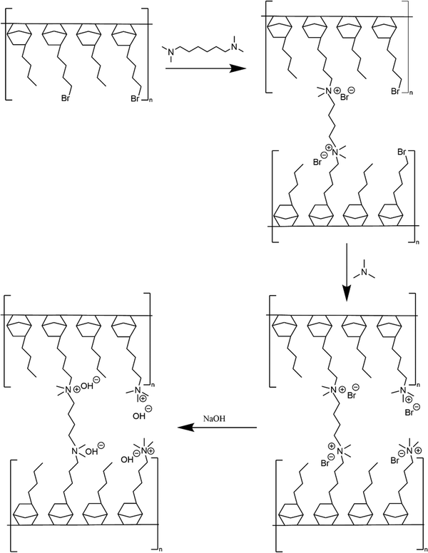
Membrane crosslinking and amination is shown in Scheme 2. Crosslinked GT75 membranes were cast using two different processes named (i) ‘conventional’ amination process’ and (ii) ‘in situ’ amination process. Both processes involved solvent-casting membranes in an aluminum pan.
The conventional membrane casting process, Scheme 3, involved stirring the GT75 polymer in toluene for 1 h followed by in situ crosslinking of the polymer by adding N,N,N′,N′-tetramethyl-1,6-hexanediamine (TMHDA) at a specific mole ratio with respect to the total moles of halogenated monomer, BrNB. The crosslinked GT75 copolymer solution was filtered through a 0.45 μm poly(tetrafluoroethylene) (PTFE) membrane syringe filter before solvent casting. The polymer solution was drop-cast onto aluminum foil or in an aluminum pan. The transparent membrane was dried in an overpressure of toluene solvent followed by oven drying at 60 °C. Amination occurred ex situ by soaking the flexible, transparent membrane in 40% aqueous trimethyl amine (TMA) for 24 h at room temperature. The quaternized membrane was washed with DI water and the bromide counter ion was exchanged for hydroxide by soaking the film in 1M NaOH solution for 1 h. Nitrogen gas was purged during the ion exchange process to limit carbonation by atmospheric CO2.
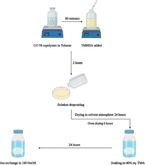 | ||
| Scheme 3 ‘Conventional’ process for preparing AEM membrane including in situ crosslinking, ex situ amination and ex situ ion–exchange. | ||
The new, ‘in situ’ process for casting anion conducting membranes is described in Scheme 4. The GT75 copolymer was dissolved in solvent and in situ crosslinking was performed by adding TMHDA, as in the conventional process, Scheme 3. The temperature of the solution was controlled at room temperature or elevated values, e.g., 40 °C under constant stirring, as described in the next section. The TMHDA was first added and stirred for 120 min followed by addition of TMA. A stoichiometric excess of aqueous TMA (e.g., 50 mol%) was added to the crosslinked polymer solution. The solution was allowed to stir for a specific time (e.g., 2 to 12 h) at specified temperatures before film casting. The films were allowed to dry in a solvent-rich atmosphere for 24 h to prevent cracking due to thermal stresses, as done in the conventional process. The films were then dried in an oven at 60 °C. The membranes were washed with DI water and soaked in 1M NaOH solution under nitrogen for an hour to convert the bromide ions into hydroxide.
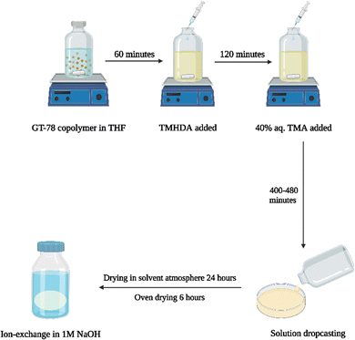 | ||
| Scheme 4 New process for AEM casting (left) showing crosslinking, quaternization, and ion exchange of GT75 copolymer (right). | ||
The membrane conductivity was measured using a four-point probe electrochemical impedance spectrometry with a PARSTAT 2273 (Princeton Applied Research) potentiostat. The conductivity of the membranes was measured in HPLC-grade water in a nitrogen atmosphere.
The ionic in-plane conductivity was calculated by eqn (1), where σ is the ionic conductivity in S cm−1, L is the length between sensing electrodes in cm. R is the resistance measured in ohms, and W and T are the width and thickness of the membranes, respectively.
 | (1) |
The IEC was determined by 1H-MMR in the pre-aminated form and confirmed by titration. 1H-NMR was used to calculate the maximum possible IEC of the GT75 copolymer from its molar composition. The IEC of the aminated membrane was titrated by first ion exchanging the membrane to the chloride form followed by chloride titration.12 Comparison of the IEC values obtained by NMR and titration showed that amination via the Menshutkin reaction was essentially 100% complete. 1H-NMR was found to be an accurate method for analyzing the IEC of fully aminated polymer samples. In this study, IEC values of aminated membranes are found by titration, and IEC values for non-aminated polymers were calculated using 1H-NMR.
The water uptake of the membranes was characterized by soaking a dry membrane in hydroxide form in DI water for 72 h. The water uptake was calculated by eqn (2), where, Mw and Md are the weight of the hydrated and dry membrane, respectively.
 | (2) |
The extractable mass loss was calculated by stirring a crosslinked membrane in OH− form in tetrahydrofuran (THF) for 72 h. Subsequently, the membranes were dried and weighed. The extractable mass loss was calculated using eqn (3), where, Mi and Mf are the dry weight before and after soaking in THF, respectively.
 | (3) |
The long-term alkaline stability was evaluated by measuring the change in ionic conductivity with time in an alkaline environment at elevated temperatures. The membranes were soaked in 1.25 M KOH at 80 °C in a Teflon-lined Parr reactor. The conductivity was measured by first washing with DI water followed by measuring the conductivity, as described above. Each data point was measured in triplicate and the average value is reported. The deviation in the measurements of each data point was <2%.
AEM alkaline electrolysis was performed, as previously described.15,19 Oxygen evolution reaction (OER) anode and hydrogen evolution reaction (HER) cathode were prepared using the solvent-cast method with the same formulation in our previous studies.15,19 OER and HER electrodes used 50![[thin space (1/6-em)]](https://www.rsc.org/images/entities/char_2009.gif) :
:![[thin space (1/6-em)]](https://www.rsc.org/images/entities/char_2009.gif) 30
30![[thin space (1/6-em)]](https://www.rsc.org/images/entities/char_2009.gif) :
:![[thin space (1/6-em)]](https://www.rsc.org/images/entities/char_2009.gif) 20 and 20
20 and 20![[thin space (1/6-em)]](https://www.rsc.org/images/entities/char_2009.gif) :
:![[thin space (1/6-em)]](https://www.rsc.org/images/entities/char_2009.gif) 60
60![[thin space (1/6-em)]](https://www.rsc.org/images/entities/char_2009.gif) :
:![[thin space (1/6-em)]](https://www.rsc.org/images/entities/char_2009.gif) 20 ionomers (butyl norbornene (BuNB):bromobutyl norbornene (BrNB):norbornene propionic acid ethyl ester (NBPEE)), respectively. 0.1 M NaOH electrolyte was fed to the OER anode.15,19 The HER cathode was operated dry. The electrolysis was performed at 60 °C. The current density was 1 A cm−2 and the water-to-gas ratio at the exit of the anode was 1.3. GT75 membrane (30 μm thick) with 5 mol% crosslinker (with respect to the available bromobutyl sites (i.e., GT75-5) used as a control. The AEM alkaline electrolyzer was conditioned at 0.1 A cm−2 until a steady-state voltage was approached. The cell current was increased in 0.25 A cm−2 steps until 1 A cm−2. The steady-state applied voltage profile was obtained at 1 A cm−2. The linear sweep voltammetry (LSV) curves were measured at 5 mV s−1. High frequency resistance (HFR) of the cells was obtained at 0.1 V using PARSTAT 2273.
20 ionomers (butyl norbornene (BuNB):bromobutyl norbornene (BrNB):norbornene propionic acid ethyl ester (NBPEE)), respectively. 0.1 M NaOH electrolyte was fed to the OER anode.15,19 The HER cathode was operated dry. The electrolysis was performed at 60 °C. The current density was 1 A cm−2 and the water-to-gas ratio at the exit of the anode was 1.3. GT75 membrane (30 μm thick) with 5 mol% crosslinker (with respect to the available bromobutyl sites (i.e., GT75-5) used as a control. The AEM alkaline electrolyzer was conditioned at 0.1 A cm−2 until a steady-state voltage was approached. The cell current was increased in 0.25 A cm−2 steps until 1 A cm−2. The steady-state applied voltage profile was obtained at 1 A cm−2. The linear sweep voltammetry (LSV) curves were measured at 5 mV s−1. High frequency resistance (HFR) of the cells was obtained at 0.1 V using PARSTAT 2273.
Results and discussions
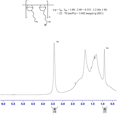
A BrNB:BuNB poly(norbornene) copolymer (GT75) was synthesized and the number average molecular weight (Mn) of the synthesized polymer was 54.7 kDa and the dispersity was 1.78. Excessively high molecular weight may decrease the processability of the polymer while a low molecular weight may lower the mechanical properties of the cast film. The IEC of the polymer was evaluated using 1H-NMR analysis (Fig. 1) by integration of the terminal methyl protons of the BuNB (peak Ha in Fig. 1) moiety and the methylene protons adjacent to the bromine atom of BrNB (peak Hb in Fig. 1). The integration ratio between Ha and Hb was used to find the IEC. The mole ratio of BuNB:BrNB for the 25![[thin space (1/6-em)]](https://www.rsc.org/images/entities/char_2009.gif) :
:![[thin space (1/6-em)]](https://www.rsc.org/images/entities/char_2009.gif) 75 monomer feed polymer was found to be 22
75 monomer feed polymer was found to be 22![[thin space (1/6-em)]](https://www.rsc.org/images/entities/char_2009.gif) :
:![[thin space (1/6-em)]](https://www.rsc.org/images/entities/char_2009.gif) 78 in the synthesized polymer. This ratio corresponds to an IEC of 3.68 meq g−1 if fully aminated.
78 in the synthesized polymer. This ratio corresponds to an IEC of 3.68 meq g−1 if fully aminated.
The amination reaction (i.e., Menshutkin reaction) is a type II SN2 reaction that proceeds via a dipolar transition state to an ionic product.20 The choice of solvent can affect the rate of reaction because the transition state is stabilized with a polar solvent.21 In this study, different membrane casting solvents were investigated in an attempt to simultaneously control the solubility of the polymer and amination rate at 40 °C, as shown in Table 1. Aprotic polar solvents were investigated because they do not form hydrogen bonds during amination, thus improving the reaction rate.21 Among common polar aprotic solvents, GT75 had good solubility in toluene, tetrahydrofuran (THF), cyclopentyl methyl ether (CPME), and 2-methyl tetrahydrofuran. However, the aminated polymer was not sufficiently soluble in 2-methyl tetrahydrofuran making it unsuitable as a membrane casting solvent. Toluene is a good membrane casting solvent, however, the aminated polymer was not very soluble causing the it to precipitate out of solution as the amination reaction reached completion. CPME was usable for casting GT75 films, however, these membranes showed little ion conductivity indicating incomplete amination. The highest solubility and membrane conductivity was found with films aminated and cast from THF. It was found that the in situ aminated polymer was soluble in THF for a longer time compared to the other solvents shown in Table 1. It appears that THF was most effective in the in situ amination-casting process because of its moderate polarity, low nucleophilicity, and good solvating properties. Therefore, THF was chosen as the solvent for further in situ amination-casting studies. In Table 1, the crosslinker concentration is the mole percent crosslinker (TMHDA) with respect to the available BrNB sites. The precast amination time is the mixing time after TMA addition before film casting, The ionic conductivity was measured at room temperature after exchanging hydroxide for bromide in the cast films. A conductivity of “ND” (not detected) indicates that the film was not suitable for measurement.
| Solvent | Crosslinker conc. | Precast amination time | Ionic conductivity (mS cm−1) | Observation |
|---|---|---|---|---|
| Toluene | 5% | 5 h | 3.13 | Fragile film |
| 5% | 6 h | 3.27 | Fragile opaque film | |
| 5% | 7 h | ND | Polymer precipitation; unable to cast film | |
| CPME | 5% | 6 h | 2.73 | Robust opaque film |
| 5% | 7 h | 2.69 | Robust opaque film | |
| 5% | 14 h | 2.79 | Robust opaque film | |
| 5% | 15 h | ND | Polymer precipitation, unable to cast film | |
| 2-Methyl THF | 5% | 0 h | ND | Casting solution hazy |
| 5% | 1 h | ND | Polymer precipitation; unable to cast film | |
| THF | 5% | 5 h | 61 | Robust film |
| 5% | 8 h | 72 | Robust film | |
| 5% | 9 h | ND | Polymer precipitation; unable to cast film |
The effect of temperature on the in situ polymer solution was investigated. In general, increasing the solution temperature increased the rate of the Menshutkin amination reaction and increased the solubility of both the pre-aminated and aminated polymer. Thus, it was desirable to increase the temperature to improve solubility but not so high as to shorten the casting time (i.e., pot life) to an unusable value. Different reaction temperatures including 35 °C, 40 °C, 45 °C, and 50 °C were investigated for the in situ AEM casting experiments. 13At temperatures above 40 °C, it was seen that the amination rate was too high, and the polymer precipitated from solution within 30 min. 40 °C was chosen as the compromise temperature where there was sufficient rate of amination and casting time.
Membranes were cast using the conventional process (i.e., post casting amination) and in situ amination process. In the conventional process, the GT75 copolymer was dissolved in toluene, crosslinked with TMHDA, and cast before amination. After drying, the membranes were soaked in TMA for different time periods to produce membranes with varying degrees of quaternization. For the in situ casting process, GT75 copolymer was dissolved in THF, and crosslinked and quaternized at 40 °C in situ before membrane casting. In this study, the term ‘amination time’ for the conventional process is the time the membrane soaked in TMA after casting. For the in situ process, we use the term ‘precast amination time’ as the time between TMA (amination) addition to the polymer solution (containing the crosslinker) and membrane casting. It is recognized that both the amination and crosslinking reactions take place during the precast time. Films with varying amination time and precast amination time were prepared.
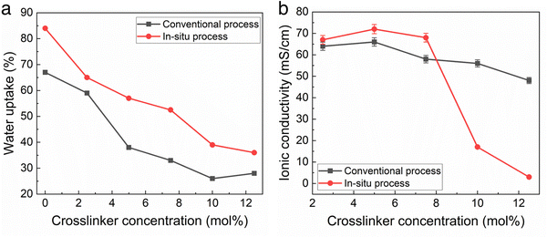
The water uptake and ionic conductivity of the conventional and in situ cast films were measured as a function of cross-linker density. The conventional process used toluene as the casting solvent with 24 h amination in TMA after casting. The in situ cast films used THF at 40 °C as the solvent with a precast amination time of 8 h. Crosslinking is an effective way to decrease water uptake which can be desirable.12Fig. 2a shows the water uptake was slightly higher for films made with the in situ casting process compared to the conventional process, at the same crosslinker concentration. In situ polymer-crosslinker mixtures greater than 12 mol% crosslinker resulted in inadequate polymer solubility before casting.
Fig. 2b shows the change in hydroxide conductivity with increasing crosslinker concentration for the films measured in Fig. 2a. Taken together, the results in Fig. 2 indicate that the TMA amination process competes very effectively with TMHDA crosslinking, perhaps resulting in in situ membranes with a slightly lower crosslink density (for the same TMHDA concentration) than the conventional films. Fig. 2b indicates that in situ cast films with less than 8 mol% TMHDA were essentially fully aminated due to the high conductivity. The drop in conductivity at higher crosslinking for the in situ method is likely due to low ion mobility.
The IEC of the membranes in Fig. 2 was measured by titration, as described in the Experimental Section. For the membranes with less than 8 mol% crosslinker, the IEC was the same as the BrNB value in the polymer obtained by 1H-NMR, within experimental error (generally +/− 2%) showing that the membranes were completely aminated.
The ability of TMHDA to crosslink the polymer during the TMA amination process was investigated by measuring the amount of unreacted TMHDA in the polymer. The unreacted TMHDA ‘extractable mass loss’ was measure, as described above. It is recognized that TMHDA remaining in the polymer (not extractable), does not necessarily mean it crosslinked the polymer because TMHDA could be immobilized by undergoing reaction at one end or by reacting both ends with the same polymer chain. However, higher extractable mass loss indicates poor crosslinking efficiency in the membrane due to the extraction of unreacted crosslinker, leading to higher water uptake. Table 2 shows the extractable mass loss from the conventional and in situ membranes with 8 mol% crosslinker from Fig. 2. This is confirmed by the results in table and Mandal et al.12 The in situ process resulted in a modest increase in conductivity and IEC, although the differences were close to the experimental error in each case. The higher water uptake and extractable mass loss for the in situ cast film indicates a lower crosslink density. It is noted that this can be mitigated by either adding additional TMHDA or by adding the TMHDA before TMA to give the crosslinking reaction a longer time.
| Property | Conventional process | In situ process |
|---|---|---|
| Maximum ionic conductivitya | 66 mS cm−1 | 72 mS cm−1 |
| Water uptake | 37% | 55% |
| IEC (titration) | 3.4 meq g−1 | 3.7 meq g−1 |
| Extractable mass loss | 2.3% | 3.1% |
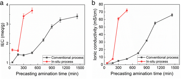
The IEC and ionic conductivity of membranes made by the conventional and new in situ amination method were compared as a function of amination time. The amination time for the conventional casting method is long, nominally >24 h, because TMA has to diffuse into the solid membrane. It is assumed that the amination reaction itself is relatively fast. For the in situ casting method, the TMA is homogenously distributed throughout the casting solution. Fig. 3 shows that the IEC and conductivity of the films made by the conventional casting method slowly increased over the 1500 min amination time. It is noted that this long process time is disruptive to the roll-to-roll membrane casting process because the polymer film has to be unrolled and soaked in TMA in order to give the membrane full exposure to the TMA solution. It would be very difficult to carry out this process in a roll-to-roll facility due to this extremely long time.
In the case of the in situ aminated films, the THF solvent allowed adequate time for precast mixing, which would not interfere with the roll-to-roll process. As noted in Table 2, the membranes made using the new in situ casting process showed slightly higher initial ionic conductivity than the conventional films, indicating either slightly higher IEC or higher ion mobility. In addition, the elevated temperature for the in situ casting process also contributes to the overall increase in reaction rate. It is also known that the rate of the Menshutkin reaction increases with temperature and solvent polarity.20,22 However, excessively high polar solvent stabilizes the transition state leading to slower reaction kinetics. THF being moderately polar increased the overall amination rate.
Fig. 3 shows the TMA/TMHDA/polymer mixing time is critical to film conductivity for the in situ process, whereas excess amination time in the conventional process does no harm. Thus, the mixing time for the in situ casting process must be tightly controlled to prevent the precipitation of the aminated polymer from solution before casting.
A photograph of the conventional cast membrane and in situ aminated membranes are shown in Fig. 4. Fig. 5 shows optical micrographs of in situ cast film aminated for an optimal time (i.e., 450 min) and an excess time (i.e., 600 min). The effect of over-amination before casting can be seen from microscopy images in Fig. 5. Increasing the precast amination time to 600 min caused microphase separation in the membrane. This led to a sharp decrease in ionic conductivity due to the non-productive nature of the two phases. Increasing the reaction time increased the phase separation and this led to an opaque looking film. Increasing the tprecast amination time to more than 600 min also led to poor quality membranes which were difficult to cast because the polymer partly precipitated from solution and lost its film-forming ability. Even for membranes that formed, they were relatively brittle and had poor mechanical strength. On the other hand, a low mixing time for the in situ process (i.e., less than 60 min in THF) led to robust, transparent films but with poor ionic conductivity, as shown in Fig. 3. It is evident that the pre-casting reaction time is critical because it is a balance between low IEC (and ionic conductivity) and poor mechanical properties. However, switching solvents from toluene (for the conventional process) to THF (for the new in situ casting process) appears to provide an adequate window of opportunity. The optimum precast amination time for the new process in THF at 40 °C was found to be between 420 to 480 min. Membranes cast in this time frame formed robust membranes with high hydroxide conductivity.
 | ||
| Fig. 4 Optical image of AEM membranes using conventional process (left) and in situ process at 450 min precastprecast amination time (right). | ||
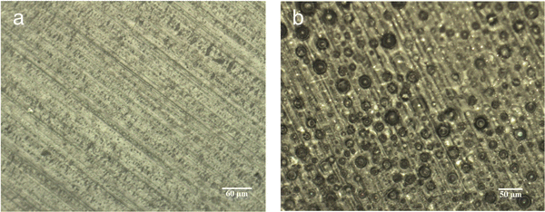 | ||
| Fig. 5 Optical microscopy images of AEM cast using the in situ process at (a) 450 min & (b) 600 min precast amination time. | ||
DSC experiments were used to characterize the glass transition temperature of the polymer. The Tg of the polymer was characterized in its quaternary ammonium form because the formation of ionic headgroups could affect the Tg of the final material. The polymer was heated from 25 to 400 °C and no Tg was detected below the decomposition temperature of the polymer.
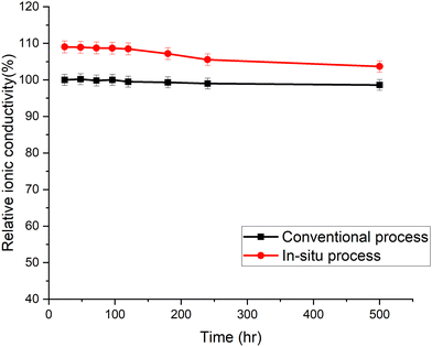
The accelerated aging of trimethyl ammonium functionalized poly(norbornene) membranes has been previously demonstrated.16 The membranes were aged at 80 °C in 1.25 M KOH. The ionic conductivity was measured periodically. Each data point in Fig. 6 is an average of three or more individual measurements. The membranes cast by the new in situ amination process had an initial conductivity higher than the conventional membrane, even though they used the same poly(norbornene) polymer and crosslinker concentration. The conductivity of the in situ aminated membrane trended toward the conventional membrane with time. The cause of this break-in period and trend is still under investigation. Detailed chemical analysis is difficult because neither membrane is soluble for quantitative 1H-NMR analysis.
The performance of the two types of membranes in an electrolyzer was investigated. Alkaline water electrolysis performance of the in situ aminated GT75 AEM was tested and compared to a commercial GT75-5 (Pention®) conventional AEM. The electrodes were fabricated as previously described.15,19Fig. 7a shows an electrolysis voltage for both the in situ aminated GT75 membrane and the commercial GT75-5 membrane measured at 1 A cm−2 for 100 h. The applied voltage of in situ aminated GT75 AEM was 1.769 V after 100 h which corresponds to 47.4 kW h kg−1 of energy input and 83.1%HHV energy efficiency without any ohmic loss correction.
 | ||
Fig. 7 AEM alkaline water electrolysis performance with in situ GT75 AEM (40 μm thick) compared to GT75-5 AEM (30 μm thick) operated using 0.1 M NaOH electrolyte and at 60 °C. (a) Steady-state applied voltage measured for 100 h at 1 A cm−2. (b) Polarization curves at BOL (closed) and EOL (open) measured at 5 mV s−1. (c) HFR at BOL and EOL. OER anode used 0.5 mg cm−2 of NiFe2O4, 0.11 mg cm−2 of 50![[thin space (1/6-em)]](https://www.rsc.org/images/entities/char_2009.gif) : :![[thin space (1/6-em)]](https://www.rsc.org/images/entities/char_2009.gif) 30 30![[thin space (1/6-em)]](https://www.rsc.org/images/entities/char_2009.gif) : :![[thin space (1/6-em)]](https://www.rsc.org/images/entities/char_2009.gif) 20 ionomer, and 0.6 mg cm−2 of adhesive, coated on Ni PTL. HER cathode used 1.2 mg cm−2 of Pt3Ni, 0.6 mg cm−2 of 20 20 ionomer, and 0.6 mg cm−2 of adhesive, coated on Ni PTL. HER cathode used 1.2 mg cm−2 of Pt3Ni, 0.6 mg cm−2 of 20![[thin space (1/6-em)]](https://www.rsc.org/images/entities/char_2009.gif) : :![[thin space (1/6-em)]](https://www.rsc.org/images/entities/char_2009.gif) 60 60![[thin space (1/6-em)]](https://www.rsc.org/images/entities/char_2009.gif) : :![[thin space (1/6-em)]](https://www.rsc.org/images/entities/char_2009.gif) 20 ionomer, and 0.1 mg cm−2 of adhesive, coated on non-wet proofed carbon paper PTL.15,19 20 ionomer, and 0.1 mg cm−2 of adhesive, coated on non-wet proofed carbon paper PTL.15,19 | ||
Fig. 7b shows the polarization curve in situ GT75 was also comparable to GT75-5. No degradation with either membrane was observed in the polarization curves. A small improvement in voltage at high current is observed after the break-in period. The beginning of life (BOL) curves (closed symbols) and end of life (EOL) curves (open symbols) are nearly identical. The curve at EOL showed improved performance compared to BOL in activation energy (at low current) and ohmic regions (high current), as usually occurs during electrolysis break-in. Fig. 7c shows the high frequency resistance (HFR) of in situ aminated GT75 cell and convention AWM. The in situ aminated AEM was 5% different from the GT75-5 at BOL. The HFR of both cells decreased by a similar amount. It is noted that the in situ aminated membrane was 33% thicker (40 μm) than the GT75-5 membrane which contributes to the slightly higher HFR. These results show that both membranes displayed durable and comparable alkaline electrolysis performance independent of the membrane fabrication process.
Conclusion
A novel process for making anion exchange membranes has been demonstrated that eliminates the long, disruptive, and dangerous post-casting amination step currently used. The new in situ amination process makes it possible to scale membrane production for roll-to-roll processing. The new in situ cast membranes showed high ionic conductivity (72 mS cm−1 at 25 °C) while still maintaining chemical stability in accelerated aging. The in situ cast membranes were crosslinked and aminated in solution prior to solvent casting. The solubility of the native and aminated polymer was improved and balanced with the rate of crosslinking and amination by changing the casting solvent (from toluene to THF) and temperature. In addition, THF allowed a longer pot life for the solution before membrane casting. Increasing the temperature of the polymer solution to 40 °C increased the solubility and rate of reaction thus decreasing the overall processing time. The time between addition of the tertiary amine and casting (precast amination time) was found to be an important parameter for this process. Increasing the precast amination time increased the ionic conductivity while still maintaining the membrane mechanical properties. Reaction time of 420 to 480 min was optimum at 40 °C. High performance alkaline water electrolysis using the new in situ aminated membrane was demonstrated at 1 A cm−2 and shown to be comparable to an existing state-of-the-art commercial AEM.Conflicts of interest
There are no conflicts to declare.Acknowledgements
The authors gratefully acknowledge the material contributions from Technetics LLC and the financial support of the U.S. Department of Energy, Office of Energy Efficiency & Renewable Energy H2@Scale program (Award Number: DE-EE0008833).References
- B. C. H. Steele and A. Heinzel, Nature, 2001, 414, 345–352 CrossRef CAS PubMed.
- N. mac Dowell, N. Sunny, N. Brandon, H. Herzog, A. Y. Ku, W. Maas, A. Ramirez, D. M. Reiner, G. N. Sant and N. Shah, Joule, 2021, 5, 2524–2529 CrossRef CAS.
- K. Ayers, Curr. Opin. Electrochem., 2019, 18, 9–15 CrossRef CAS.
- T. Wang, X. Cao and L. Jiao, Carbon Neutrality, 2022, 1, 21 CrossRef.
- J. R. Varcoe, P. Atanassov, D. R. Dekel, A. M. Herring, M. A. Hickner, P. A. Kohl, A. R. Kucernak, W. E. Mustain, K. Nijmeijer, K. Scott, T. Xu and L. Zhuang, Energy Environ. Sci., 2014, 7, 3135–3191 RSC.
- D. W. Shin, M. D. Guiver and Y. M. Lee, Chem. Rev., 2017, 117, 4759–4805 CrossRef CAS PubMed.
- D. R. Dekel, J. Power Sources, 2018, 375, 158–169 CrossRef CAS.
- S. Gottesfeld, D. R. Dekel, M. Page, C. Bae, Y. Yan, P. Zelenay and Y. S. Kim, J. Power Sources, 2018, 375, 170–184 CrossRef CAS.
- J. Pan, J. Han, L. Zhu and M. A. Hickner, Chem. Mater., 2017, 29, 5321–5330 CrossRef CAS.
- Z. Sun, B. Lin and F. Yan, ChemSusChem, 2018, 11, 58–70 CrossRef CAS PubMed.
- J. Pan, C. Chen, L. Zhuang and J. Lu, Acc. Chem. Res., 2012, 45, 473–481 CrossRef CAS PubMed.
- M. Mandal, G. Huang and P. A. Kohl, ACS Appl. Energy Mater., 2019, 2, 2447–2457 CrossRef CAS.
- F. Xu, Y. Su and B. Lin, Front Mater., 2020, 7, 4 CrossRef.
- X. He, J. Liu, H. Zhu, Y. Zheng and D. Chen, RSC Adv., 2015, 5, 63215–63225 RSC.
- H. Park, P. N. Shah, H. M. Tee and P. A. Kohl, J. Power Sources, 2023, 564, 232811 CrossRef CAS.
- E. J. Park, C. B. Capuano, K. E. Ayers and C. Bae, J. Power Sources, 2018, 375, 367–372 CrossRef CAS.
- G. Huang, M. Mandal, X. Peng, A. C. Yang-Neyerlin, B. S. Pivovar, W. E. Mustain and P. A. Kohl, J. Electrochem. Soc., 2019, 166, F637–F644 CrossRef CAS.
- W. N. Albrecht and R. L. Stephenson, Scand. J. Work, Environ. Health, 1988, 14, 209–219 CrossRef CAS PubMed.
- H. M. Tee, H. Park, P. N. Shah, J. A. Trindell, J. D. Sugar and P. A. Kohl, J. Electrochem. Soc., 2022, 169, 124515 CrossRef CAS.
- M. Sola, A. Lledos, M. Duran, J. Bertran and J. L. M. Abboud, J. Am. Chem. Soc., 1991, 113, 2873–2879 CrossRef CAS.
- H. T. Turan, S. Brickel and M. Meuwly, J. Phys. Chem. B, 2022, 126(9), 1951–1961 CrossRef CAS PubMed.
- W. Zheng, S. A. Yamada, S. T. Hung, W. Sun, L. Zhao and M. D. Fayer, J. Am. Chem. Soc., 2020, 142, 5636–5648 CrossRef CAS PubMed.
| This journal is © The Royal Society of Chemistry 2023 |


