 Open Access Article
Electrochemical oxidation of 5-hydroxymethylfurfural over a molybdenum sulfide modified nickel-based catalyst†
Zijia
Li
a,
Yingyi
Han
a,
Baobing
Huang
*b,
Zailai
Xie
 a and
Qiao-Hua
Wei
 *a
*a
aFujian Key Laboratory of Electrochemical Energy Storage Materials, College of Chemistry, Fuzhou University, 2 Xueyuan Road, Fuzhou 350016, China. E-mail: qhw76@fzu.edu.cn
bSchool of Advanced Manufacturing, Fuzhou University, 1 Shuicheng Road, Jinjiang 362200, China. E-mail: baobinghuang@fzu.edu.cn
First published on 11th May 2023
Abstract
Biomass derived small molecules are sustainable feedstocks to synthesize high value-added products. Herein, we demonstrate a facile one-pot hydrothermal method to fabricate a molybdenum sulfide modified nickel-based catalyst for the electrochemical oxidation of HMF to 2,5-furandicarboxylic acid (FDCA). The as-synthesized catalyst shows a unique nano-flower-like microstructure with features of a large surface area, excellent conductivity and high-valence Mo species. Electrochemical tests indicate that the onset potential increases to 1.27 V after the addition of HMF, which is much lower than that of water oxidation. This change suggests that the oxidation of HMF occurs before the slow kinetic oxygen evolution reaction (OER), potentially acting as an alternative to the OER cathodic reaction to drive hydrogen evolution and CO2 reduction. Moreover, the reaction achieves 100% conversion and 99% selectivity, which is because molybdenum sulfide accelerates the in situ oxidation of Ni2+ to NiOOH and Ni3+. This study provides a new pathway for the conversion of HMF into FDCA, a promising substitute for the petroleum derivative terephthalic acid.
1. Introduction
With the development of modern society, the demand for energy and daily necessities is constantly increasing, which inevitably leads to a huge consumption of limited fossil resources such as coal, crude oil and natural gas.1 Thus scientists are committed to developing renewable, Earth-rich biomass as an alternative to chemical sources to provide a sustainable supply chain.2 Among them, lignocellulosic biomass 5-hydroxymethylfurfural (HMF) is listed as one of the top ten biomass derived molecules by the United States Department of Energy. Due to the presence of furan rings and hydroxyl and aldehyde functional groups,3–5 HMF is a multi-purpose platform chemical. It can also be easily obtained from sugars and then converted into valuable chemicals or biofuel.1,2,6,7 2,5-Furandicarboxylic acid (FDCA) is one of the typical products of all, and can be used to obtain a variety of unique biological polyesters.5,8 For example, the polycondensation reaction between FDCA and ethylene glycol results in the formation of polyethylene glycol 2,5-furandiformate (PEF), which is not only an alternative of petroleum-based polyethylene terephthalate (PET), but also a versatile polyester with excellent thermal stability9 and gas barrier properties.10,11Electrocatalytic oxidation of HMF (HMFOR) is an effective method to achieve a high yield of FDCA at normal temperature and pressure. Compared with the OER, HMF oxidation has a lower oxidation initial potential and a higher current density at the same potential. Therefore, it can significantly reduce the battery voltage and replace the slow oxygen evolution reaction (OER) to achieve efficient cathode hydrogen production.12–15 But there is a complex reaction process, in which the combined adsorption/desorption behavior of organic molecules and the hydroxyl group is considered the key step,16 while OHad is the critical intermediate in the catalytic cycle of the OER and alcohol molecules. The H* generated by hydroxyl group dehydrogenation in the oxidation step of alcohol molecules binds with OHad17,18 in an alkaline solution, which has been widely recognized.17,19 Since the HMFOR includes the oxidation of hydroxyl and aldehyde groups, each oxidation only occurs at the specific reaction sites, resulting in a low catalytic efficiency.20 Therefore, it is important for the rational design of efficient catalysts to solve the adsorption competition on the catalyst surface at the atomic level. In view of these, many homogeneous or heterogeneous catalysts with various metals as the active components have been proved to be useful for the electrocatalytic oxidation of HMF.21 Noble metal (Au, Pt, Pd, Ru, etc.)5,22–25 based catalysts show considerable catalytic performance, but their relatively high cost makes researchers focus on the development of inexpensive and efficient non-noble metal (Ni, Co, Mn, Ce, etc.)26–28 based catalysts. Ni-based catalysts are some of the most excellent catalysts for catalyzing the oxidation of HMF, and various Ni-based materials show good catalytic activity because of their appropriate electronic configuration, rich valence states and diverse composition.29,30 Driven by ions, the Ni metal will be oxidized to a high valence state, and then it will spontaneously and quickly return to the original Ni2+, which is the process of anodizing.31,32 The results show that the more high-valence the Ni forms, the more the active sites formed, thus improving the performance of the catalyst.33,34 In other words, by optimizing the electronic structure of the catalyst, more Ni sites can be activated to oxidize HMF. In order to modify Ni sites to promote the oxidation of HMF, element doping is an effective strategy, which is conducive to promoting the evolution of single-component catalysts to multi-component catalysts with synergistic effects, so as to obtain high performance catalysts. Therefore, a high-valence Mo metal is added to adjust the active site of the material, so as to promote charge transfer and meet the needs of continuous catalysis.35,36 However, the presence of bimetals will cause a positive electric field on the electrode surface to be too strong, thus affecting the desorption of products and the adsorption of a large number of intermediates. Therefore, the S2− anions can reduce the positive electric field intensity, which is conducive to the generation of organic products, so as to achieve a better catalytic yield and conversion rate.37 However, this bimetallic material still needs a more in-depth study and understanding, which will help in accurately understanding the catalytic mechanism of this catalyst and guide researchers to synthesize more targeted and efficient catalysts in the future.38
In this work, we design a molybdenum sulfide modified nickel-based catalyst (Ni-MoSx/NF) for the HMFOR. The nano-flower-like amorphous molybdenum sulfides (MoSx) can be grown on nickel foam using a traditional one pot hydrothermal method. The high-resolution XPS spectrum shows that Mo mainly exists in the form of MoS3, wherein the high-valence of Mo6+ can promote the faster oxidation of Ni2+ into NiOOH and Ni3+, leading to the rapid conversion of HMF into FDCA. Therefore, the Ni-MoSx/NF catalyst delivers 100% conversion and 99% selectivity for the HMFOR with an onset potential of 1.27 V (vs. RHE), which is superior to those of most of the nickel-based catalysts.
2. Experimental section
2.1 Chemicals and materials
5-Hydroxymethylfurfural (HMF, 99.0%), 2,5-diformylfuran (DFF, 98.0%), 5-hydroxymethyl-2-furancarboxylic acid (HMFCA, 98.0%), 5-formyl-2-furancarboxylic acid (FFCA, 98.0%) and 2,5-furandicarboxylic acid (FDCA, 98.0%) were all purchased from Admas. Potassium hydroxide (KOH), nickel(II) nitrate hexahydrate (Ni(NO3)2·6H2O), ammonium molybdate tetrahydrate ((NH4)6 Mo7O24·4H2O), thiourea (CH4N2S), and ethanol (EtOH) were all purchased from Alfa Aesar and used as received unless otherwise noted. All aqueous solutions are prepared using nanopure deionized water (Thermo Scientific Banstead Nanopure). Nickel foam (NF) was purchased from TaoBao and subjected to cleaning and removal of surface oxides before use. Specifically, NF was first ultrasonically cleaned in 6 mmol HCl solution for 30 minutes and then treated with deionized water and ethanol for 15 minutes, respectively.2.2 Synthesis of the Ni-MoSx/NF
First, 0.264 g of Ni(NO3)2·6H2O, 0.64 g of (NH4)6Mo7O24·4H2O and 0.15 g of CH4N2S were successively added to 30 mL of deionized water and stirred for one hour to make it completely dissolved into a green and clear solution. This solution was then transferred to a 50 mL PTFE-lined stainless steel reactor with a 1 cm × 1 cm pretreated piece of nickel foam on the bottom and placed in a 110 °C oven for 8 hours. After cooling to room temperature, the sample was rinsed with deionized water and ethanol for 5 minutes to remove the surface attachments. The Ni-MoSx/NF was finally obtained by further drying at 60 °C under vacuum overnight.2.3 Synthesis of the Ni3S2/NF
The preparation process of Ni3S2/NF is similar to that of Ni-MoSx/NF without the addition of (NH4)6Mo7O24·4H2O.2.4 Structural characterization
X-Ray powder diffraction (XRD, RIGAKU Ultima IV, Rigaku Corporation of Japan Co., Ltd) with high-intensity Cu-Kα (λ = 1.54 á) radiation was used to get the phase structure. The microstructure of the sample was determined by scanning electron microscopy (SEM, Verios G4) and transmission electron microscopy (TEM, TECNAI G2 F20). Similarly, the elemental distribution of the sample can be obtained from the X-ray energy-dispersive spectrometer (EDS) by TEM. The valence state distribution of the elements was characterized by X-ray photoelectron spectroscopy (XPS, ESCALAB 250 Xi).2.5 Electrochemical measurements
The reaction was carried out at room temperature using the CHI-660E electrochemical workstation. The electrochemical oxidation synthesis took place at the anode through an H-type electrolytic cell, which was separated by a Nafion115 cation exchange membrane, and the electrolyte was 1 M KOH. The whole reaction used a three-electrode system: the nickel foam with the catalyst grown served as the working electrode which was connected with a glassy carbon electrode clamp, an Ag/AgCl electrode was used as the reference electrode of the anode, and a platinum wire electrode was used as the counter electrode of the cathode. The formula of the reversible hydrogen electrode (RHE) was as follows:| E(RHE) = E(Ag/AgCl) + 0.197 + 0.059pH |
In all electrochemical tests of this work, 18 mL of KOH (1 M) was added to the anode and cathode respectively. The electrocatalytic oxidation of HMF (HMFOR) and the oxygen evolution reaction (OER) occurred with and without HMF (10 mM) at the anode, respectively. Before the test, cyclic voltammetry (CV) was used to activate the electrode, and the scanning rate was 50 mV s−1. The electrical double-layer capacitance (Cdl) was calculated by CV curves under different scanning rates (20–200 mV s−1). The scanning rate of the polarization curve (LSV) was 5 mV s−1, and the Tafel slope was calculated using it. Electrochemical impedance spectroscopy (EIS) was measured at 1.64 V, with a frequency range of 100![[thin space (1/6-em)]](https://www.rsc.org/images/entities/char_2009.gif) 000 Hz to 0.01 Hz. The cycle performance of HMF oxidation was tested three times by chronoamperometry, and the selected voltage was 1.55 V. The electrochemical tests reported in this study did not have iR compensation, and the electrochemical anode and cathode reactions were as follows:
000 Hz to 0.01 Hz. The cycle performance of HMF oxidation was tested three times by chronoamperometry, and the selected voltage was 1.55 V. The electrochemical tests reported in this study did not have iR compensation, and the electrochemical anode and cathode reactions were as follows:
| Anode reaction: HMF + 6OH− → FDCA + 4H2O + 6e− |
| Cathode reaction: 6H2O + 6e− → 3H2 + 6OH− |
| Overall reaction: HMF + 2H2O → FDCA + 3H2 |
2.6 Quantitative product analysis
All the reactants, products and possible intermediates in the reaction process were qualitatively and quantitatively determined using the liquid chromatography binary gradient method (LC-20A from Shimadzu, Japan). The detector was an ultraviolet detector and a D2 lamp was used to obtain the signal of the liquid to be measured. The temperature of the column temperature box was 40 °C, and the detection wavelength was set to 265 nm. Deionized water was used as mobile phase A and methanol as mobile phase B at a ratio of 1![[thin space (1/6-em)]](https://www.rsc.org/images/entities/char_2009.gif) :
:![[thin space (1/6-em)]](https://www.rsc.org/images/entities/char_2009.gif) 1 and a total flow rate of 1 mL min−1. For testing, 10 μL of the solution was taken from the electrolytic cell, diluted to 1 mL, and finally 20 μL of the diluted solution was injected into a C18 chromatographic column. The external standard method was used to quantify all the solutions to be tested according to the configured pure components of known concentration. The formulas used were as follows:
1 and a total flow rate of 1 mL min−1. For testing, 10 μL of the solution was taken from the electrolytic cell, diluted to 1 mL, and finally 20 μL of the diluted solution was injected into a C18 chromatographic column. The external standard method was used to quantify all the solutions to be tested according to the configured pure components of known concentration. The formulas used were as follows:where F is the Faraday constant (96
![[thin space (1/6-em)]](https://www.rsc.org/images/entities/char_2009.gif) 485 C mol−1).
485 C mol−1).
3. Results and discussion
As depicted in Fig. 1, the samples were synthesized using a facile one-pot hydrothermal method. Typically, Ni(NO3)2·6H2O, (NH4)6Mo7O24·4H2O and CH4N2S in a certain ratio were mixed evenly in deionized water, then transferred to a hydrothermal reactor containing pretreated nickel foam sheets of 1 cm × 1 cm, and reacted at 110 °C for 8 h. After rinsing with deionized water and ethanol and drying overnight, we obtained the final product molybdenum sulfide modified nickel foam-based catalyst (Ni-MoSx/NF) with a unique nano-flower-like morphology. The preparation process of Ni3S2/NF was similar to that of Ni-MoSx/NF without the addition of (NH4)6Mo7O24·4H2O.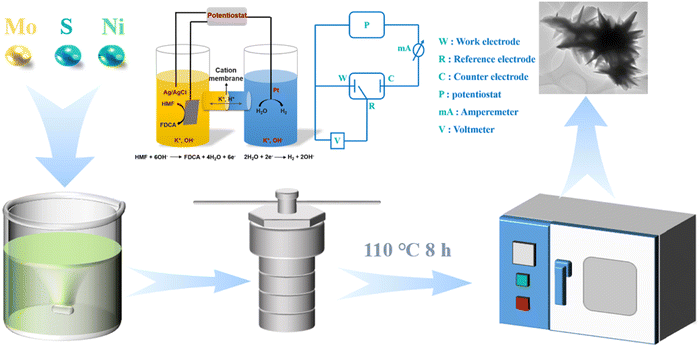 | ||
| Fig. 1 Schematic diagram of the material synthesis and the electrochemical system used for HMF oxidation. | ||
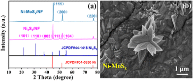
X-ray diffraction (XRD) was first used to study the crystal structure and phase composition of the as-synthesized samples. As shown in Fig. 2a, the XRD characteristic peaks at 44.5°, 51.8° and 76.3° respectively correspond to the (111), (200) and (220) crystal planes of nickel foam (JCPDF # 04-0850). Besides, the extra diffraction peaks at 21.7°, 31.1°, 37.7°, 50.1° and 54.6° in the Ni3S2/NF sample are ascribed to the (101), (110), (003), (113) and (104) crystal planes of Ni3S2 (JCPDF # 44-1418). However, no additional diffraction peaks are present in the Ni-MoSx/NF samples. It is speculated that the addition of a Mo source induces the formation of an amorphous structure, which will also be confirmed by subsequent high resolution transmission electron microscopy (HRTEM) images.
Then, scanning electron microscopy (SEM) combined with transmission electron microscopy (TEM) was used to observe the microscopic morphology of the samples. It can be evidently observed from Fig. 2b and Fig. S1 (ESI†) that Ni-MoSx exists as nanoflowers on the surface of nickel foam, which could be conducive to the adsorption of small organic molecules and the exposure of active sites. The TEM image in Fig. 3a also reveals a similar flower-like structure of Ni-MoSx, which is in good agreement with the SEM image. Furthermore, there is no lattice fringe on the catalyst surface observed by the HRTEM and SAED images (Fig. 3b and c), which proves once again the existence of amorphous molybdenum sulfide. The mapping images in the selected area reveal the uniform distribution of the elements in Ni-MoSx (Fig. 3d) and the atomic ratio of them is Mo![[thin space (1/6-em)]](https://www.rsc.org/images/entities/char_2009.gif) :
:![[thin space (1/6-em)]](https://www.rsc.org/images/entities/char_2009.gif) Ni
Ni![[thin space (1/6-em)]](https://www.rsc.org/images/entities/char_2009.gif) :
:![[thin space (1/6-em)]](https://www.rsc.org/images/entities/char_2009.gif) S = 8
S = 8![[thin space (1/6-em)]](https://www.rsc.org/images/entities/char_2009.gif) :
:![[thin space (1/6-em)]](https://www.rsc.org/images/entities/char_2009.gif) 3
3![[thin space (1/6-em)]](https://www.rsc.org/images/entities/char_2009.gif) :
:![[thin space (1/6-em)]](https://www.rsc.org/images/entities/char_2009.gif) 2 (Table S1, ESI†). It can be seen from Fig. 3f–i that these elements are evenly distributed on the surface.
2 (Table S1, ESI†). It can be seen from Fig. 3f–i that these elements are evenly distributed on the surface.
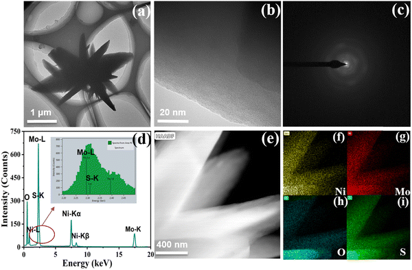 | ||
| Fig. 3 (a) TEM image of the dark field; (b and c) HRTEM and SAED image; (d) EDS image; (e) TEM image of the bright field and (f–i) mapping images in the selected area of Ni-MoSx/NF. | ||
The specific surface elements and their valence states of the samples were further characterized by X-ray photoelectron spectroscopy (XPS). As shown in Fig. 4a, the XPS survey spectrum indicates the existence of Ni, Mo, S and O elements in the Ni-MoSx/NF. Furthermore, the high-resolution spectra of Ni 2p and Mo 3d are shown in Fig. 4b and c. The fitted peaks of Ni 2p1/2 (873.4 eV) and Ni 2p3/2 (855.8 eV) and their satellite peaks (861.8 eV and 879.7 eV) belong to the Ni2+ species.39,40 The Mo 3d spectrum shows two strong peaks at 232.3 eV and 235.4 eV, which belong to Mo 3d5/2 and Mo 3d3/2 of Mo6+, respectively,41,42 proving that Mo mainly exists in the form of MoS3. The high-valence of Mo6+ can promote the faster oxidation of Ni2+ into NiOOH. In addition, the XPS results of Ni-MoSx/NF and Ni3S2/NF are compared to elucidate their electronic structural characteristics. As shown in Fig. S2 (ESI†), the Ni ion shows two valence states Ni0 and Ni2+ before doping, which conforms to the valence state of Ni in Ni3S2. Furthermore, the O 1s peak moves significantly towards the lower binding energy, indicating the optimization and redistribution of the doped electronic structure in Ni-MoSx (Fig. 4d).
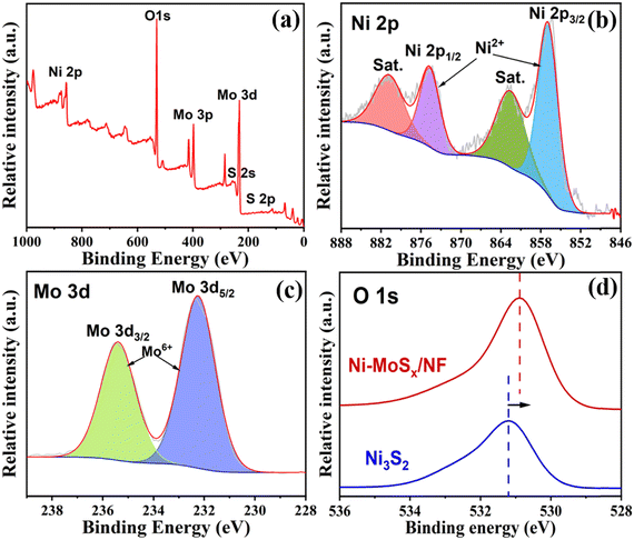 | ||
| Fig. 4 (a) Survey spectrum, (b) Ni 2p and (c) Mo 3d high-resolution spectrum of the Ni-MoSx/NF. (d) O 1s high-resolution spectra. | ||
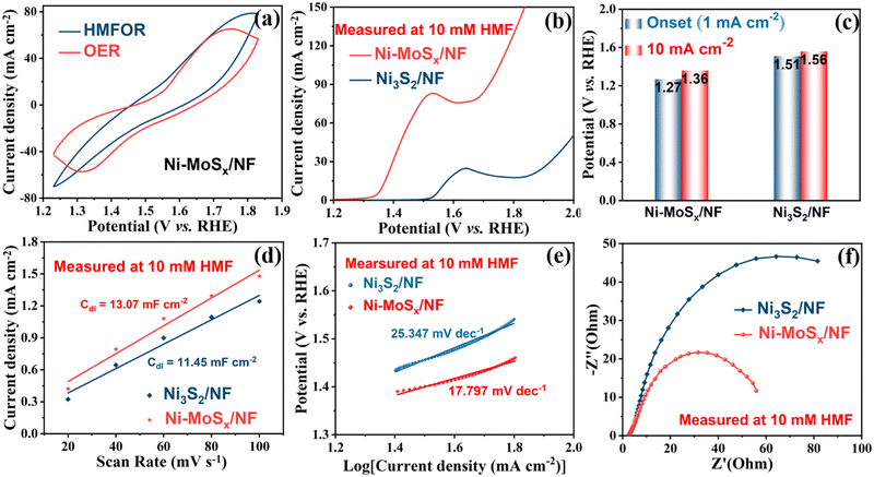
The HMF electrochemical oxidation test was carried out using the H-type electrolytic cell (Fig. S3, ESI†), with platinum wire as the counter electrode, Ag/AgCl as the reference electrode and the as-synthesized Ni-MoSx/NF or Ni3S2/NF as the working electrode. The cyclic voltammetry (CV) curves in Fig. 5a were measured with or without HMF in 1 M KOH solution. Without reactants, the OER occurs at the anode of the electrolytic cell, and two symmetrical redox peaks can be found from the red curve. However, after the addition of HMF, it disappeared in the blue curve and was attributed to the inhibition of oxidation of the Ni-MoSx/NF catalyst itself in the HMFOR. Obviously, there is a bulge accompanied due to the oxidation of Ni2+ and the formation of NiOOH beginning at 1.27 V (Fig. 5b), which is less than 1.51 V of the catalyst without MoSx (Fig. 5c). Ni-MoSx/NF also has a lower potential of 1.36 V than 1.56 V of Ni3S2/NF at the same current density of 10 mA cm−2. In addition, further research shows that the HMFOR has a lower potential than that of the OER at the same current density of 10 mA cm−1 (Fig. S4, ESI†), which reveals that the HMFOR is superior to the OER at low potentials. In order to further explore the oxidation performance of Ni-MoSx/NF, Fig. S5 (ESI†) shows the CV curves at different scanning rates in the unladen efficiency region, and the current response in this region is only attributed to the double-layer capacitor. The electrical double-layer capacitance Cdl in HMF oxidation is compared in Fig. 5d. According to the calculations, the Cdl of Ni-MoSx/NF (13.07 mF cm−2) is larger than that of Ni3S2/NF (11.45 mF cm−2), indicating that Ni-MoSx/NF has a higher electrochemical active surface area, and further provides more catalytic active sites, which may be conducive to the HMF oxidation. The electrochemical active surface area (ECSA) normalized polarization curves are presented in Fig. S6 (ESI†) to reflect the intrinsic activity of different samples.
Moreover, the kinetic factors of the catalysts are analyzed in Fig. 5e. According to the calculation of the corresponding polarization curve, the Tafel slope of Ni-MoSx/NF in HMF oxidation is only 17.797 mV dec−1, which is lower than 25.347 mV dec−1 of Ni3S2/NF and demonstrates the excellent electron transfer rate, which confirms that Ni-MoSx/NF exhibits a higher oxidation rate and faster reaction kinetics toward HMF oxidation. In addition, the electrode kinetics of the HMFOR is quantified by electrochemical impedance spectroscopy (EIS). Fig. 5f shows that Ni-MoSx/NF has a smaller semicircle diameter of the Nyquist curve, indicating the lower charge transfer resistance and better conductivity, which illustrates that the catalyst modified by MoSx has excellent characteristics in charge catalysis and mass transfer in the HMFOR process.
The chronoamperometry of HMF oxidation was conducted at a constant potential of 1.55 V. As shown in Fig. 6b and c, both the anode and the cathode contain 18 mL of KOH (1 M), and extra 10 mM HMF was added to the anode. After calculations, the theoretical power is 104C. It was clearly visible that the yellowish solution containing HMF rapidly turned into a clear solution after the oxidation reaction. In order to study the product distribution during the entire oxidation process, high performance liquid chromatography was used for quantitative analysis. The oxidation of HMF to FDCA mainly takes place through two routes (Fig. 6a): Route A is that the aldehyde group in HMF is first oxidized to 5-hydroxymethyl-2-furanic acid (HMFCA) and Route B is that the hydroxyl group is first oxidized to 2,5-dicarbofuran (DFF). These two intermediate products can be further oxidized to form 5-formyl-2-furanic acid (FFCA) and finally FDCA.
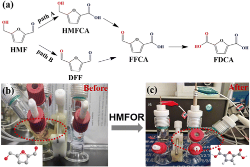 | ||
| Fig. 6 (a) Two reaction paths of HMF oxidation to FDCA. (b and c) Digital photograph showing the color change of the anodic electrolyte during the electrochemical HMF oxidation process. | ||
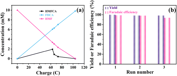
It can be seen that the amount of HMF decreases while the amount of FDCA increases as the reaction proceeds (Fig. 7a). The signal of the intermediate HMFCA is also detected, which increases first and then decreases as the oxidation reaction proceeds through path A (Fig. 6a). It indicates that the aldehyde group in HMF is more easily oxidized than the hydroxyl group in an alkaline environment. There are no other intermediate products detected, which illustrates that the conversion of HMFCA into FFCA and then into FDCA is a rapid process, so the generation of HMFCA is a decisive step in the whole process. The current density–time curve of the reaction was measured at a voltage of 1.55 V, as shown in Fig. S7 (ESI†). HMF oxidation occurred before 6000 s, and the OER occurred after 6000 s since the reactants were completely transformed. As the reactant begins to adsorb on the electrode surface, the current density drops rapidly at the beginning of the reaction and decreases to some extent with a decrease in the reaction concentration in the electrolyte. As shown in Fig. 7b, under the catalysis of Ni-MoSx/NF, the reaction finally achieves 100% faradaic efficiency and 99% selectivity. The conversion rate and faradaic efficiency of three successive electrolysis cycles can all reach above 90%, which outperforms previously reported electrocatalysts (Table 1). In terms of catalytic stability, the performance slightly reduces after the third cycle, which may be due to the loss of partial catalyst during the continuous washing and drying of the surface of the Ni-MoSx/NF catalyst. Overall, the high faradaic efficiency and selectivity indicate that the Ni-MoSx/NF catalyst has great potential for application.
| Catalyst | FE (%) | Yield (%) | Conditions and onset potential | Ref. |
|---|---|---|---|---|
| Ni3N@C nanosheets | 99 | 98 | 10 mM HMF, 1.0 M KOH, 1.45 V (vs. RHE) | 24 |
| NiCo2O4 on Ni foam | 87.5 | 90.4 | 5 mM HMF, 1.0 M KOH, 1.5 V (vs. RHE) | 43 |
| NiFe LDH nanosheets | 99.4 | 98 | 10 mM HMF, 1.0 M KOH, 1.23 V (vs. RHE) | 25 |
| NiO–Co3O4 | 96 | 98 | 10 mM HMF, 1.0 M KOH, 1.28 V (vs. RHE) | 44 |
| NiBx-P0.07 | 92.5 | 90.6 | 10 mM HMF, 0.1 M KOH, 1.46 V (vs. RHE) | 45 |
| Thick NiOOH films | 96 | 96 | 5 mM HMF, 0.1 M KOH, 1.47 V (vs. RHE) | 46 |
| Ni-MoSx/NF | 100 | 99 | 10 mM HMF, 1.0 M KOH, 1.27 V (vs. RHE) | This work |
4. Conclusions
Molybdenum sulfide modified nickel foam based catalysts were successfully prepared using a facile one-pot hydrothermal method. The nano-flower-like Ni-MoSx/NF catalyst demonstrated the best catalytic performance toward HMF electrochemical oxidation to FDCA with 100% conversion and 99% selectivity, superior to those of the reported catalysts. This great catalytic performance can be ascribed to its large electrochemically active surface area and excellent conductivity. More importantly, high-valence Mo effectively promotes the rapid conversion of Ni2+ to Ni3+ during the HMFOR. The high faradaic efficiency also indicates that HMF oxidation has more dynamic advantages than water oxidation at low potential. These positive results suggest that this work not only provides an effective method for the direct synthesis of biomass derived platform chemicals for electrochemical anodes, but also an excellent anode substitution reaction for cathode coupled hydrogen production.Author contributions
Zijia Li: methodology, writing – original draft, formal analysis, and investigation. Yingyi Han: validation and formal analysis. Baobing Huang: validation and writing – review & editing. Zailai Xie: supervision and writing – review & editing. Qiao-Hua Wei: supervision and writing – review & editing.Conflicts of interest
The authors declare that they have no known competing financial interests or personal relationships that could have appeared to influence the work reported in this paper.Acknowledgements
This work was supported by the National Natural Science Foundation of China (22072018 and 52202035) and the Natural Science Foundation of Fujian Province (2021J06010 and 2021J05140).References
- I. Staffell, D. Scamman, A. Velazquez, P. Balcombe, P. E. Dodds, P. Ekins, N. Shah and K. R. Ward, Energy Environ., 2019, 12, 463–491 RSC.
- C. Tang, Y. Zheng, M. Jaroniec and S. Qiao, Angew. Chem., Int. Ed., 2021, 60, 19572–19590 CrossRef CAS PubMed.
- J. J. Bozell and G. R. Petersen, Green Chem., 2010, 12, 539–554 RSC.
- X. Kong, Y. Zhu, Z. Fang, J. A. Kozinski, I. S. Butler, L. Xu, H. Song and X. Wei, Green Chem., 2018, 20, 3657–3682 RSC.
- Z. Zhang and K. Deng, ACS Catal., 2015, 5, 6529–6544 CrossRef CAS.
- S. Chu, Y. Cui and N. Liu, Nat. Mater., 2016, 16, 16–22 CrossRef PubMed.
- R. J. Van Putten, J. C. Van der Waal, E. De Jong, C. B. Rasrendra, H. J. Heeres and J. G. De Vries, Chem. Rev., 2013, 113, 1499–1597 CrossRef CAS PubMed.
- A. C. Dreischarf, M. Lammert, N. Stock and H. Reinsch, Inorg. Chem., 2017, 56, 2270–2277 CrossRef CAS PubMed.
- S. K. Burgess, J. E. Leisen, B. E. Kraftschik, C. R. Mubarak, R. M. Kriegel and W. J. Koros, Macromolecules, 2014, 47, 1383–1391 CrossRef CAS.
- T. Debuissy, E. Pollet and L. Avérous, ChemSusChem, 2018, 11, 3836–3870 CrossRef CAS PubMed.
- M. Sajid, X. Zhao and D. Liu, Green Chem., 2018, 20, 5427–5453 RSC.
- J. Song, C. Wei, Z. F. Huang, C. Liu, L. Zeng, X. Wang and Z. J. Xu, Chem. Soc. Rev., 2020, 49, 2196–2214 RSC.
- X. Chen, J. Liu, T. Yuan, Z. Zhang, C. Song, S. Yang, X. Gao and N. Wang, Energy Mater., 2022, 2, 200028 Search PubMed.
- Z. Wang, Z. Li, Y. Chao, Y. Cui, X. He, P. Liang, C. Zhang and Z. Zhang, Energy Mater., 2022, 2, 200019 CrossRef.
- C. Yang, N. Gao, X. Wang, J. Lu, L. Cao, Y. Li, Y. Li and H. P. Liang, Energy Mater., 2021, 1, 100015 CrossRef.
- M. T. Bender, Y. C. Lam, S. Hammes-Schiffer and K. S. Choi, J. Am. Chem. Soc., 2020, 142, 21538–21547 CrossRef CAS PubMed.
- Y. Lu, T. Liu, C. L. Dong, Y. C. Huang, Y. Li, J. Chen, Y. Zou and S. Wang, Adv. Mater., 2021, 33, e2007056 CrossRef PubMed.
- P. Pal and S. Saravanamurugan, ChemSusChem, 2019, 12, 145–163 CrossRef CAS PubMed.
- W. Chen, C. Xie, Y. Wang, Y. Zou, C. L. Dong, Y. C. Huang, Z. Xiao, Z. Wei, S. Du, C. Chen, B. Zhou, J. Ma and S. Wang, Chem, 2020, 6, 2974–2993 CAS.
- X. Han, C. Li, Y. Guo, X. Liu, Y. Zhang and Y. Wang, Appl. Catal., A, 2016, 526, 1–8 CrossRef CAS.
- X. Jiang, W. Li, Y. Liu, L. Zhao, Z. Chen, L. Zhang, Y. Zhang and S. Yun, SusMat, 2023, 3, 21–43 CrossRef CAS.
- A. Lolli, S. Albonetti, L. Utili, R. Amadori, F. Ospitali, C. Lucarelli and F. Cavani, Appl. Catal., A, 2015, 504, 408–419 CrossRef CAS.
- B. Siyo, M. Schneider, J. Radnik, M. M. Pohl, P. Langer and N. Steinfeldt, Appl. Catal., A, 2014, 478, 107–116 CrossRef CAS.
- J. Xie, J. Nie and H. Liu, Chin. J. Catal., 2014, 35, 937–944 CrossRef CAS.
- G. Yi, S. P. Teong and Y. Zhang, Green Chem., 2016, 18, 979–983 RSC.
- Z. Zhang and G. W. Huber, Chem. Soc. Rev., 2018, 47, 1351–1390 RSC.
- N. Zhang, Y. Zou, L. Tao, W. Chen, L. Zhou, Z. Liu, B. Zhou, G. Huang, H. Lin and S. Wang, Angew. Chem., Int. Ed., 2019, 58, 15895–15903 CrossRef CAS PubMed.
- W. J. Liu, L. Dang, Z. Xu, H. Q. Yu, S. Jin and G. W. Huber, ACS Catal., 2018, 8, 5533–5541 CrossRef CAS.
- C. Yang, S. Yun, J. Shi, M. Sun, N. Zafar, A. Arshad, Y. Zhang and L. Zhang, Chem. Eng. J., 2021, 419, 129636 CrossRef CAS.
- Y. Zhang, S. Yun, J. Dang, C. Dang, G. Yang, Y. Wang, Z. Liu and Y. Deng, Mater. Today Phys., 2022, 27, 100785 CrossRef CAS.
- M. Yuan, X. Guo, N. Li and H. Pang, J. Colloid Interf. Sci., 2021, 589, 56–64 CrossRef CAS PubMed.
- Z. Yue, S. Yao, Y. Li, W. Zhu, W. Zhang, R. Wang, J. Wang, L. Huang, D. Zhao and J. Wang, Electrochem. Acta, 2018, 268, 211–217 CrossRef CAS.
- M. Sun, S. Yun, J. Dang, Y. Zhang, Z. Liu and D. Qiao, Chem. Eng. J., 2013, 458, 141301 CrossRef.
- J. Dang, S. Yun, Y. Zhang, G. Yang, J. Yang, D. Qiao and T. Yang, J. Colloid Interf. Sci., 2023, 630, 91–105 CrossRef CAS PubMed.
- P. F. Liu, S. Yang, L. R. Zheng, B. Zhang and H. G. Yang, Chem. Sci., 2017, 8, 3484–3488 RSC.
- Z. Liu, S. Yun, M. Sun, J. Dang, Y. Zhang, Y. Wang, C. Dang, Y. Deng and D. Qiao, Mater. Today Nano, 2022, 20, 100274 CrossRef CAS.
- M. Sun, S. Yun, J. Shi, Y. Zhang, A. Arshad, J. Dang, L. Zhang, X. Wang and Z. Liu, Small, 2022, 17, 2102300 CrossRef PubMed.
- Y. Zhang, S. Bi, Z. Niu, W. Zhou and S. Xie, Energy Mater., 2022, 2, 200012 CrossRef.
- L. Li, K. S. Hui, K. N. Hui and Y. R. Cho, J. Mater. Chem. A, 2017, 5, 19687–19696 RSC.
- J. Wang, X. Ma, T. Liu, D. Liu, S. Hao, G. Du, R. Kong, A. M. Asiri and X. Sun, Mater. Today Energy, 2017, 3, 9–14 CrossRef.
- M. Q. Yu, L. X. Jiang and H. G. Yang, Chem. Commun., 2015, 51, 14361–14364 RSC.
- X. Zhu, Z. Wang, K. Zhong, Q. Li, P. Ding, Z. Feng, J. Yang, Y. Du, Y. Song, Y. Hua, J. Yuan, Y. She, H. Li and H. Xu, Chem. Eng. J., 2022, 429, 132204 CrossRef CAS.
- M. J. Kang, H. Park, J. Jegal, S. Y. Hwang, Y. S. Kang and H. G. Cha, Appl. Catal., B, 2019, 242, 85–91 CrossRef CAS.
- Y. Lu, C. L. Dong, Y. C. Huang, Y. Zou, Y. Liu, Y. Li, N. Zhang, W. Chen, L. Zhou, H. Lin and S. Wang, Sci. China: Chem., 2020, 63, 980–986 CrossRef CAS.
- X. Song, X. Liu, H. Wang, Y. Guo and Y. Wang, Ind. Eng. Chem. Res., 2020, 59, 17348–17356 CrossRef CAS.
- B. J. Taitt, D. H. Nam and K. S. Choi, ACS Catal., 2018, 9, 660–670 CrossRef.
Footnote |
| † Electronic supplementary information (ESI) available. See DOI: https://doi.org/10.1039/d3ma00104k |
| This journal is © The Royal Society of Chemistry 2023 |


