DOI:
10.1039/D2MA01027E
(Paper)
Mater. Adv., 2023,
4, 1135-1145
A Pd-anchored poly(vinyl chloride-co-maleic acid monoamide)/poly(vinyl chloride) ultrafiltration membrane for the efficient degradation of 4-nitrophenol†
Received
11th November 2022
, Accepted 15th January 2023
First published on 17th January 2023
Abstract
An ultrafiltration (UF) membrane was prepared using a blend of poly(vinyl chloride) (PVC) and low molecular weight poly(vinyl chloride-co-maleic acid monoamide) (PVMA), demonstrating a significantly improved filtration flux. For example, the water flux of the membrane fabricated with PVMA/PVC (50/50 wt%/wt%) was boosted to 691.67 L m−2 h−1vs. 64.66 L m−2 h−1 for the pure PVC membrane, while the porosity of the UF membranes was 88.6% vs. 74.7%, respectively. Employing immobilized palladium nanoparticles as a catalyst, the Pd-PVMA/PVC membrane offered an efficiency as high as 99.0%, which remained greater than 97.0% over three cycles at a filtration flux of 208.75 L m−2 h−1 for the degradation of 4-nitrophenol (4-NP). The catalytic reaction exhibited first-order kinetics and the apparent kinetic reaction constant was as high as 2.65 × 10⁻³ s−1 at a relatively low Pd nanoparticle loading. In this study, we developed a simple method to prepare PVC UF membranes with high water flux and efficiency for the removal of 4-NP by coupling the catalytic and separation processes.
Introduction
Ultrafiltration (UF) membranes, which are capable of degrading refractory organics with supported catalysts, are widely used in the treatment of wastewater from the pharmaceutical and textile industries. Compared with common porous particulate catalyst carriers,1 membranes have more effective contact areas with the substrate via forced convection through their pores and accelerate the diffusive transport from the solutes to the catalyst sites.2,3 Moreover, catalytic membranes, coupling the reaction and separation processes in a continuous-flow system, exhibit many unique advantages such as simple operation, automation, simple reaction control and catalyst reuse.4,5 Metal nanoparticles (NPs), as catalysts loaded on membranes, are of great interest due to their excellent catalytic efficiency.3 The common metal catalysts are noble and transition metals including Cu,2 Ag,4,6 Au, Ni,7 Co,8 Pt and Pd.9,10 Ma et al.2 developed single-atom Cu(I) catalysts anchored on a thiol-doped reactive membrane for water purification. Derami et al.11 reported that a palladium nanoparticle-decorated mesoporous polydopamine/bacterial nanocellulose membrane could effectively remove dyes and various contaminants with different charges and chemical structures. Thus, UF membranes with supported metal catalysts have become increasingly important in water treatment.
However, UF membranes, which are commonly fabricated using polyether sulfone (PES), polysulfonamide (PSA), polyvinylidene fluoride (PVDF), polyacrylonitrile (PAN) and polyvinyl chloride (PVC), are susceptible to fouling during real industrial operations. Furthermore, the interactions between pollutants and membrane surface result in the deposition of sludge or colloids, and therefore usually lead a significant reduction in flux in a short operation time. It is well-known that the introduction of hydrophilic chains or chemical groups can effectively improve the anti-fouling performance of membranes without scarifying their separation efficiency. The existing hydrophilic modification technologies include surface zwitterionicalization,12 surface grafting,13 surface coating,14 embedding hydrophilic nanoparticles,15 and polymer blending.16,17 Surface coating is relatively simple and efficient but usually suffers from brushing off, pore blocking, and reduction in flux. Grafting polymerization requires multiple chemical steps due to the fact that the employed polymers lack reactive groups in their chains. Surface zwitterionicalization can endow membranes a stable hydration layer to boost their anti-fouling performance due to the electrostatic interaction between water molecules and ions. In the case of the embedded hydrophilic nanoparticles, the casting solution formulated with inorganic nanoparticles and polymers is usually not stable, and thus may lead to an inhomogeneous dispersion of nanoparticles in the membranes. Compared with hydrophilic modification technologies, polymer blending is a relatively easy and widely used process, in which polymers and modifiers are added to the casting solution simultaneously.
PVC is one of the most widely used polymers for the fabrication of UF membranes due to its chemical stability and competitive cost. Some blending modifiers, such as lignin,17 polyvinyl butyral,18 polyvinyl pyrrolidone (PVP),19 poly(ethylene glycol),20 multi-walled carbon nanotube-grafted-graphene oxide,21 SiO222 and TiO223 nanoparticles, have been applied to improve the hydrophilicity and antifouling performance of PVC UF membranes. However, it still remains a great challenge to achieve hydrophilicity and immobilize metal catalysts simultaneously because PVC is incompatible with most hydrophilic polymers and lacks reactive groups.24
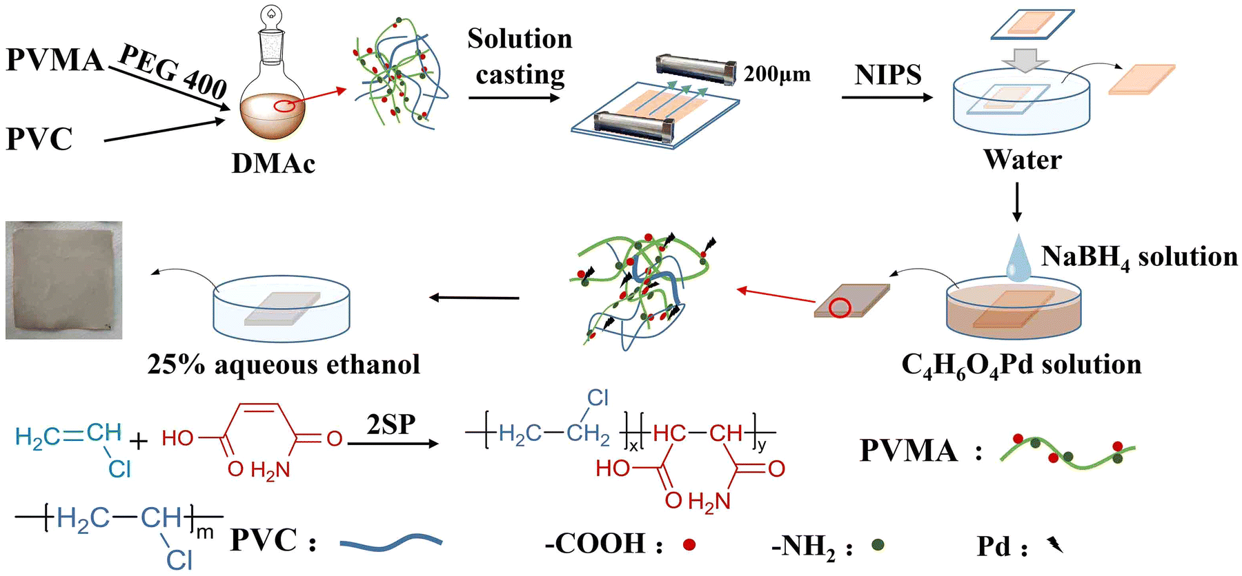
Maleic acid monoamide (MALA) is a water-soluble monomer, which can copolymerize with other monomers such as styrene and vinyl acetate to synthesize amphiphilic polymers. In addition, the –COOH and –NH2 groups in the MALA molecule enable the copolymer to adsorb and chelate metal ions.25–27 Herein, low molecular weight poly(VCM-co-MALA) (PVMA) was synthesized via self-stabilized precipitation polymerization (2SP).28–32 Then, PVMA was used as a modifier and blended with PVC to fabricate PVC UF membranes with hydrophilic nature, which supported Pd0 to couple the catalysis and separation performance. The preparation process is illustrated in Fig. 1 with poly(ethylene glycol) 400 as the pore-forming agent by non-solvent-induced phase separation (NIPS). The hydrophilicity and dye-removal capacity of the UF membrane were also studied systematically. The water flux of the membrane fabricated with PVMA/PVC (50/50 wt%/wt%) was boosted to 691.67 L m−2 h−1. The Pd-anchored PVMA/PVC (Pd-PVMA/PVC) membrane offered an efficiency as high as 99.0%, which remained greater than 97.0% over three cycles at a filtration flux of 208.75 L m−2 h−1 for the degradation of 4-nitrophenol (4-NP). The apparent kinetic reaction constant of the catalytic reaction was as high as 2.65 × 10⁻³ s−1 at a relatively low Pd nanoparticle loading. In addition, the PVMA/PVC UF membrane offers a platform for loading other catalysts for various catalytic membranes.
 |
| | Fig. 1 Formation of Pd-PVMA/PVC ultrafiltration membrane. | |
Results and discussion
Synthesis of PVMA
2SP is a facile process to prepare sub-micro-size polymer particles in the absence of any stabilizer or dispersant.32 The produced copolymer chains precipitate from the reactant to form nuclei and the successively formed copolymer chains are adsorbed or deposited onto the nuclei or particles. Then, monodisperse copolymer particles with controlled particle size can be obtained.28,30 Cui et al.33 synthesized PVC with an ultra-low number-average molecular weight in the range of 4000 to 15![[thin space (1/6-em)]](https://www.rsc.org/images/entities/char_2009.gif) 000 via 2SP. Herein, the 2SP of VCM and MALA was carried out using methanol as the dilutant, which could dissolve both MALA and VCM. The chemical structure of produced PVMA was confirmed by FTIR and 1H NMR spectroscopy. Compared with PVC, the new peaks at 1618 cm−1 and 1692 cm−1 belong to the C
000 via 2SP. Herein, the 2SP of VCM and MALA was carried out using methanol as the dilutant, which could dissolve both MALA and VCM. The chemical structure of produced PVMA was confirmed by FTIR and 1H NMR spectroscopy. Compared with PVC, the new peaks at 1618 cm−1 and 1692 cm−1 belong to the C![[double bond, length as m-dash]](https://www.rsc.org/images/entities/char_e001.gif) O stretching vibration of the amide I band and –COOH, respectively. The broad absorption bands in the range of 3200 cm−1 to 3700 cm−1 are assigned to –OH and –NH2, respectively. These results support the successful synthesis of PVMA (Fig. 2a). Also, a peak appeared at 1736 cm−1, which is ascribed to the CO stretching vibration of –COR. To further verify the structure of PVMA, the 1H NMR spectra of PVMA and PVC (Fig. 2b) were measured. It can be observed that the absorption peak of the carboxyl protons (–COOH) appeared at 13.2 ppm and amino protons (–NH2) appeared at 7.3 ppm and 7.8 ppm. The chemical shift at 4.2–4.7 ppm belongs to the proton of –CH2CHCl–. Besides, a new absorption peak at 3.69 ppm could be observed clearly, which combined with the FTIR results, is likely related to the methyl protons (–COOCH3) from the esterification reaction of MALA during polymerization in methanol. Herein, the side reaction resulted in the esterification product between MALA with methanol, which was termed MAM.
O stretching vibration of the amide I band and –COOH, respectively. The broad absorption bands in the range of 3200 cm−1 to 3700 cm−1 are assigned to –OH and –NH2, respectively. These results support the successful synthesis of PVMA (Fig. 2a). Also, a peak appeared at 1736 cm−1, which is ascribed to the CO stretching vibration of –COR. To further verify the structure of PVMA, the 1H NMR spectra of PVMA and PVC (Fig. 2b) were measured. It can be observed that the absorption peak of the carboxyl protons (–COOH) appeared at 13.2 ppm and amino protons (–NH2) appeared at 7.3 ppm and 7.8 ppm. The chemical shift at 4.2–4.7 ppm belongs to the proton of –CH2CHCl–. Besides, a new absorption peak at 3.69 ppm could be observed clearly, which combined with the FTIR results, is likely related to the methyl protons (–COOCH3) from the esterification reaction of MALA during polymerization in methanol. Herein, the side reaction resulted in the esterification product between MALA with methanol, which was termed MAM.
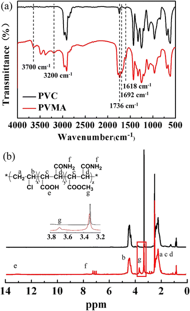 |
| | Fig. 2 (a) FTIR spectra of PVMA and PVC. (b) 1H NMR spectra of PVMA and PVC. | |
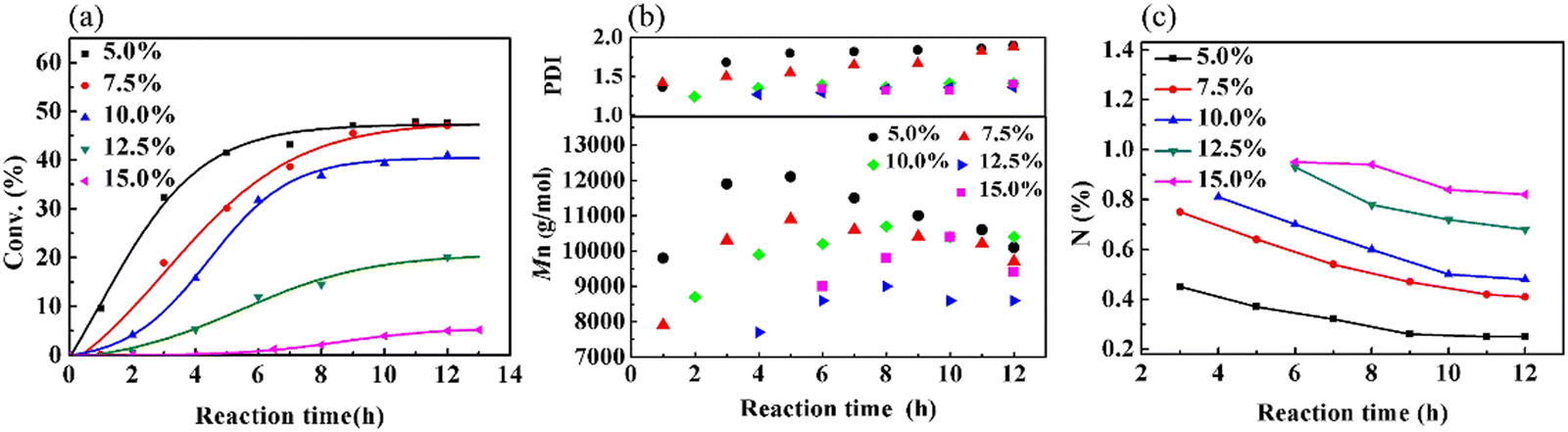
Because the polymerization of VCM is susceptible to the reaction temperature (Tr), a series of experiments was performed to study the influence of Tr on the copolymerization of VCM and MALA (Fig. S1(a) and Table S1, ESI†). Furthermore, the effects of monomer concentration (Fig. S1(b), ESI†) and bis(4-tert-butyl cyclohexyl)peroxydicarbonate (TBCP) concentration (Fig. S1(c), ESI†) on the polymerization kinetics, the Mn of the obtained copolymer and the content of MALA in the produced copolymers were also investigated (for a detailed discussion, please refer to ESI,† Table S2 and S3). The composition of the copolymer is mainly dependent on the monomer ratio. Fig. 3(a) shows that both the reaction and conversion rates decreased with an increase in the low-reactivity MALA in the monomer feed. When the addition of MALA reached 15%, the yield was only 5.2%. Fig. 3(b) shows the changes in Mn and PDI with reaction time. Initially, Mn increased, and then decreased due to the decrease in monomer concentration and generated more products of lower molecular weight and there was a gradual increase in PDI in the later stage of the reaction. The decrease in N content, as shown in Fig. 3(c), supports that the VCM structural unit in the copolymer gradually increased as the reaction progressed. The reason is likely due to the higher reactivity of VCM than that of MALA. Further analysis, as shown in Fig. S2(a and b) (ESI†), indicated that MAM increased, while MALA decreased with an increase in reaction time due to the esterification reaction. When the amount of MALA added was 7.5%, 10.0% and 15.0% in the monomer feed, the content of MALA in the copolymers was very close, but the content of MAM gradually increased. The PVMA with high conversion rate and high MALA and MAM contents could be controlled by the feed ratio and reaction time.
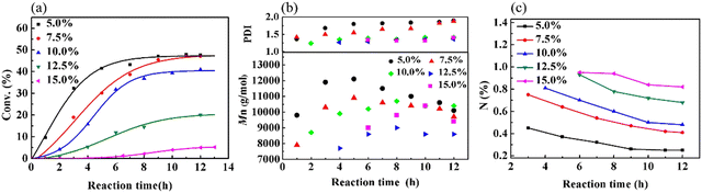 |
| | Fig. 3 Graphs of (a) conversion, (b) Mn and PDI, and (c) content of N over time at different monomer ratios. | |
By studying the different reaction conditions, the efficient PVMA preparation method with high MALA ratio was optimized. With a monomer concentration of 20%, initiator dosage of 4%, MALA to VCM feed ratio of 1:9, and reaction at 50 °C for 6 h, the monomer conversion was about 30% and the MALA content in the prepared PVMA was 3.91 wt%. A high content of MALA can provide more anchoring sites for Pd and further improve the dye interception ratio of the UF membrane. The PVMA used to prepare the PVMA/PVC UF membrane was synthesized under these conditions.
PVC/PVMA UF membrane
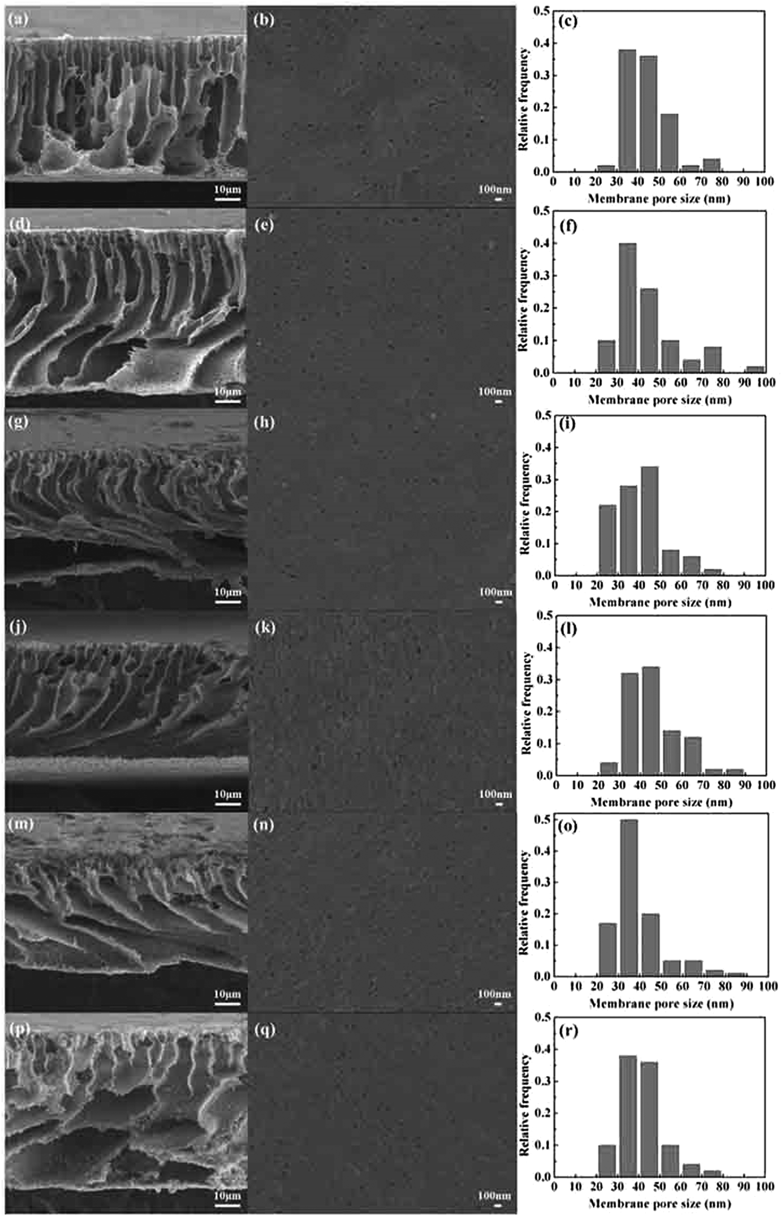
Fig. 4 shows the pore size and distribution on the surface and the cross section of the PVMA/PVC UF membrane with different contents of PVMA. With the addition of low Mn PVMA, the denser skin layer and fingerlike porous middle layer became thinner and the macro voids at the bottom of the membrane became larger. This is mainly due to the faster exchange rate between the solvent and the non-solvent by the additive of hydrophilic PVMA and decrease in the viscosity of the casting membrane solution. The pore size distribution and surface mean pore size calculated using the SEM images and ImageJ are presented in Fig. 4 and Table 1. With an increase in the PVMA fraction in the blend, the surface pore sizes were mainly in the range of 30 to 50 nm and did not change significantly. However, the porosity of the UF membrane increased from 74.67% to 88.55% when the amount of PVMA increased from 0% to 50%. Different from the surface mean pore sizes, the mean pore sizes calculated using Formula (3) increased from 52 nm to 116 nm with an increase in PVMA (Table 1), supporting the formation of large macro voids under the thin top layer. The basically steady surface pore size enabled the UF membrane to maintain excellent rejection and greatly increased the water flux. When the amount of PVMA was 50%, the pure water flux increased to 691.7 L m−2 h−1, which is almost 10.6 times than that of pure PVC (64.7 L m−2 h−1). Zhu et al.12 improved the pure water flux of a PVC UF membrane from 137.5 L m−2 h−1 to 259.6 L m−2 h−1via surface zwitterionicalization. Saberi et al.22 improved the pure water flux of a PVC hollow-fiber UF membrane from 99 L m−2 h−1 to 137 L m−2 h−1 by incorporating silica nanoparticles and Yong et al.17 blended lignin in a PVC UF membrane and improved its pure water flux from 111.6 L m−2 h−1 to 347.2 L m−2 h−1. Liu et al.34 blended the poly(ethylene oxide)-b-poly(propylene oxide)-b-poly(ethylene oxide) triblock copolymer (Pluronic F127) in a PVC/chlorinated PVC UF membrane and the pure water flux increased from 38.5 L m−2 h−1 to 209.0 L m−2 h−1. In the case of these different modification methods, the pure water flux increased by 1.9, 1.4, 3.1 and 5.4 times, respectively, which are much lower than the 10.6 in this work.
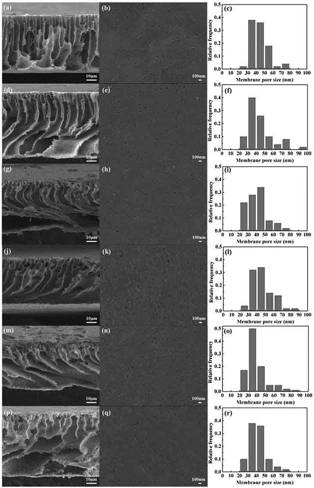 |
| | Fig. 4 Cross-sectional, surface SEM images and pore size distribution histograms of PVMA/PVC membranes: (a–c) 0 wt% PVMA, (d–f) 10 wt% PVMA, (g–i) 20 wt% PVMA, (j–l) 30 wt% PVMA, (m–o) 40 wt% PVMA, and (p–r) 50 wt% PVMA. | |
Table 1 The characteristics of PVMA/PVC ultrafiltration membrane
|
|
PVMA (wt%) |
Porosity (%) |
Surface mean pore sizea (nm) |
Mean pore sizeb (nm) |
Pure water flux (L m−2 h−1) |
|
Measured by ImageJ software.
Calculated using Formula (3).
|
| 1 |
0 |
74.67 |
43 |
52 |
64.7 |
| 2 |
10 |
77.67 |
45 |
62 |
98.0 |
| 3 |
20 |
81.22 |
34 |
90 |
271.4 |
| 4 |
30 |
83.48 |
45 |
100 |
348.4 |
| 5 |
40 |
86.38 |
33 |
102 |
443.5 |
| 6 |
50 |
88.55 |
42 |
116 |
691.7 |
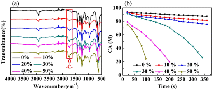
Fig. 5(a) displays the FTIR-ATR spectra of the PVMA/PVC membranes with different contents of PVMA. Compared with pure PVC, the stretching vibration absorption peak of the CO bonds at 1692 cm−1 supports the presence of PVMA on the membrane surface. The gradually increased ratio of the CO to C–Cl peak heights from 0.25 to 0.51 demonstrated the increasing content of PVMA. The broad absorption peak in the range of 3200 cm−1 to 3700 cm−1, belonging to –OH and –NH2, confirms the existence of MALA hydrophilic segments of PVMA on the membrane surface. As shown in Fig. 5(b), the variation in the dynamic water contact angles of the PVMA/PVC membranes was highly reliant on the proportions of PVMA and rest time. In detail, the initial CA values of the PVMA/PVC membranes decreased with an increase in PVMA from 0% to 50%. This is consistent with the FTIR-ATR results, demonstrating an increasing amount of hydrophilic PVMA on the membrane surface. When the amount of PVMA was up to 10% or 20%, the CA of the UF membrane slightly decreased over the whole rest time. Compared with the pure PVC UF membrane, the CA was only reduced by 1° at 20 s and 6° for PVMA(10%)/PVC and 12° PVMA(20%)/PVC after 360 s, respectively. Interestingly, when the amount of PVMA increased to 30%, the CA decreased significantly from 91° to 26° within 320 s. With a continuous increase in PVMA to 40% and even to 50%, the CA at 20 s dropped to 79° and 74°, while it dropped to 24° at 190 s and 100 s, respectively. Thus, the amount of PVMA added should not be less than 30% to obtain a good hydrophilic UF membrane.
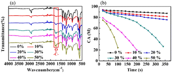 |
| | Fig. 5 (a) FTIR-ATR spectra. (b) CA of PVC and PVMA/PVC membranes with the times. | |
Pd-PVMA/PVC UF membrane
4-NP is a highly toxic dye and is difficult to biodegrade, which may cause severe harm to both the environment and human beings.35 The United States Environmental Protection Agency (US EPA) classified 4-NP as a significant pollutant.36 Even the inhalation or ingestion of a low dosage 4-NP can cause headaches, nausea, lethargy, and central nervous system damage in humans.37,38 Therefore the degradation of 4-NP has been intensively studied using various catalysts.39–42 The catalytic reaction of 4-NP transforming to 4-aminophenol (4-AP) is directly related to the Pd loading and the catalytic reaction time. During the fabrication of the Pd-PVMA/PVC UF membrane, the viscosity of the casting solution increased with an increase of the Mn and concentration of PVC, which made the membrane surface denser, thereby decreasing the water flux and increasing the catalytic reaction time. By adjusting the concentration of the casting solution, membranes with a lower porosity and pure water flux were prepared. As shown in Table 2, the membranes with different contents of PVMA were named sample 1–5. When the concentration of the casting solution increased from 11.1% to 14.3%, the porosity, mean pore size and pure water flux all decreased. Particularly, the pure water flux decreased significantly after loading Pd, and the lower the amount of PVMA added, the larger the change in the pure water flux. When the proportion of PVMA added was 10% and 50%, the pure water flux became 0.05 and 0.69 times that of the original (without loaded Pd), respectively. Under this condition, the catalytic reaction time of sample 4 was just 3.8 min for 10 mL 4-NP solution. In comparison, Rao et al.43 fabricated an Ni nanoparticle (NP)@Ag/C-carbon nanotube (CNT) composite membrane with a pure water flux of 97 L m−2 h−1. Wang et al.44 prepared a GO-Ag/PVDF/F127 membrane for the catalytic reduction of 4-nitrophenol with a pure water flux of 87.1 L m−2 h−1. Compared with the 208.7 L m−2 h−1 of sample 4 in this work, the lower pure water flux increased the transmembrane catalytic time and reduced the catalytic efficiency. The results of the ICP-OES test showed that the anchored Pd increased from 0.46 wt% to 1.05 wt% when the amount of PVMA increased from 10% to 50%. Presumptively, with an increase in the amount of PVMA added, both the pure water flux and Pd load increased; however, their effects on dye removal efficiency are opposite.
Table 2 The characteristics of the PVMA/PVC ultrafiltration membrane
| Sample |
PVMA (wt%) |
Porosity (%) |
Mean pore size (nm) |
Pure water flux (L m−2 h−1) |
Pd (wt%) |
| 1 |
10 |
66.81 |
28 |
5.2 |
0.46 |
| 2 |
20 |
71.83 |
70 |
42.1 |
0.68 |
| 3 |
30 |
78.76 |
88 |
186.9 |
0.72 |
| 4 |
40 |
82.45 |
98 |
208.7 |
0.83 |
| 5 |
50 |
86.00 |
114 |
480.0 |
1.05 |
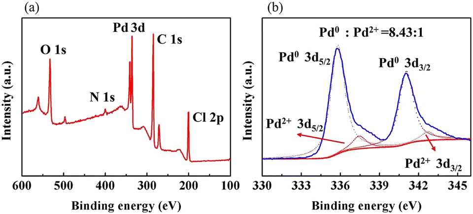
As shown in Fig. 6(a), the XPS elemental survey spectrum of sample 5 demonstrates two peaks at 341.08 eV and 335.78 eV for Pd 3d5/2 and Pd 3d3/2, respectively. The fitted Pd 3d XPS spectrum is shown in Fig. 6(b). The two peaks at 335.79eV and 341.05eV are assigned to Pd0 and the peaks at 337.44eV and 342.70eV to Pd2+. Their area ratio is 8.43:1, which shows that most Pd2+ is reduced to catalytic Pd0. Combined with the EDX elemental mapping images in Fig. 7, Pd was successfully loaded and evenly distributed on the PVMA/PVC membrane.
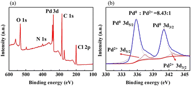 |
| | Fig. 6 (a) XPS spectra of sample 5 and (b) high-resolution XPS spectrum of Pd 3d of sample 5. | |
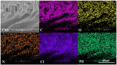 |
| | Fig. 7 EDX mapping images of C, N, O, Cl and Pd of sample 5. | |
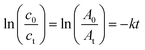
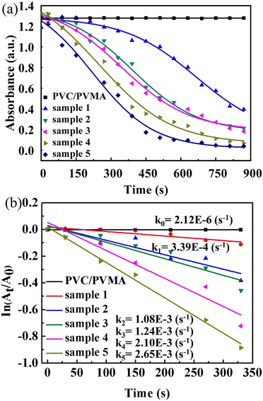
The plots of 4-NP degradation over time are shown in Fig. 8(a). As the control group, the PVMA/PVC membrane almost had no capability of degrading and/or removing the dye. Conversely, using the Pd0-loaded PVMA and with an increase in its amount, the dye removal became more efficient. The kinetic curves of the PVMA/PVC and Pd-PVMA/PVC membrane catalytic reaction, as shown in Fig. 8(b), confirm that there is a good linear relationship between the degradation reaction of the dye and reaction time. The rate constant was estimated via first-order kinetics according to the following formula:
| |  | (1) |
where
t is the reaction time,
c0 and
ct represent the initial and
t time concentrations of 4-NP, respectively,
A0 and
At refer to the UV-vis absorbance of 4-NP at the initial and
t moments, respectively, and
k is the reaction rate constant. The
k of the PVMA/PVC membrane without Pd is close to 0 s
−1, while the
k of the Pd-PVMA/PVC membranes increased from 3.4 × 10
−4 s
−1 to 2.65 × 10
−3 s
−1 as the PVMA content increased from 10 wt% to 50 wt%, which is mainly due to the increase in Pd loading. Compared with the published data summarized in
Table 3, the kinetic reaction constants of the Pd-PVMA/PVC membrane are much higher with a smaller efficient area and lower Pd NPs loading. The PVMA/PVC UF membrane with excellent porosity and hollow structure provided sufficient sites for the Pd loading and catalytic reaction. The uniformly distributed loading sites effectively prevented the agglomeration of Pd and offered well-dispersed Pd higher catalytic efficiency.
 |
| | Fig. 8 (a) Plots of 4-NP degradation by PVMA/PVC and Pd-PVMA/PVC membranes in the presence of NaBH4 with time and (b) kinetic curves of PVMA/PVC and Pd-PVMA/PVC membrane catalytic reaction. | |
Table 3 Comparison of the 4-NP catalytic reduction in this work with that in the literature
| Membrane |
Efficient area (cm2) |
NP loading |
Optimal conditions |
Kinetic reaction constant (s−1) |
Ref. |
| NiNPs@Ag/C-CNTs |
12.56 |
0.8 mg cm−2 |
4-NP (50 mL, 0.72 mM) |
2.62 × 10⁻³ |
43
|
| NaBH4 (0.30 M) |
| PP-g-EDA@Ag/Cu |
5.73 |
Ag: 1.18%, Cu: 2.43% |
4-NP (100 mL, 1.00 mM) |
4.13 × 10⁻³ |
45
|
| PP-g-DEA@Ag/Cu |
Ag: 0.75%, Cu: 0.12% |
NaBH4 (0.53 M) |
2.41 × 10⁻³ |
| Go-Ag/PVDF/F127 |
3850.00 |
Ag: 1.04% |
4-NP (0.027 mM) |
4.07 × 10⁻² |
44
|
| NaBH4 (0.048 M) |
| PVDF/PMAA-Au |
17.90 |
Au: 0.15% |
4-NP (500 mL, 1.44 × 10⁻⁴ mM) |
3.00 × 10⁻⁴ |
46
|
| PVDF/PMAA-Pd |
Pd: 0.06% |
NaBH4 (0.36 M) |
2.00 × 10⁻⁴ |
| Ag-PES/TA |
4.00 |
Ag: 5.50% |
4-NP (250 mL, 0.30 mM) |
2.40 × 10⁻⁴ |
47
|
| NaBH4 (0.05 M) |
| Pd-mPDA-BNC |
1.00 |
Pd: 20.30% |
4-NP (1.5 mL, 0.11 mM) |
6.27 × 10⁻³ |
11
|
| NaBH4 (0.0015 M) |
| Pd-PVMA/PVC |
1.00 |
Pd: 1.05% |
4-NP (3.5 mL, 0.07 mM) |
2.65 × 10⁻³ |
This work |
| NaBH4 (0.01 M) |
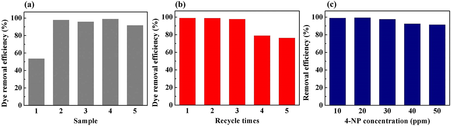
To demonstrate the feasibility of the Pd-PVMA/PVC membrane for catalytic dye removal, a 4-NP solution (10 mL 10 ppm) was filtered in the presence of NaBH4 at 0.08 MPa. The UV-vis spectra of simulated dye wastewater before and after membrane filtration are shown in Fig. 9. The color of the 4-NP solution is green, while its catalytic product 4-AP is colorless. After catalytic filtration, the absorption peak of 4-NP at 403 nm weakened or disappeared, while the peak of 4-AP at 305 nm appeared, which confirmed the efficiency of the catalytic reaction. Combined with the dye removal efficiency of the Pd-PVMA/PVC membranes with different PVMA concentrations, as shown in Fig. 10(a), it was found that the dye removal efficiency did not increase linearly with an increase in the content of PVMA. When the concentration of PVMA was 20 wt% and 40 wt%, the dye removal efficiencies were 97.9% and 99.0%, respectively, but when the amount further increased to 50 wt% the dye removal efficiencies decreased to 91.8%. This because the dye removal efficiency was influenced by both the Pd loading and water flux of the membrane. When the amount of PVMA was 50 wt%, although the Pd loading increased, the water flux increased greatly from 208.75 L m−2 h−1 to 480.00 L m−2 h−1, which shortened the catalytic reaction time significantly, and thus reduced the dye removal efficiency accordingly.
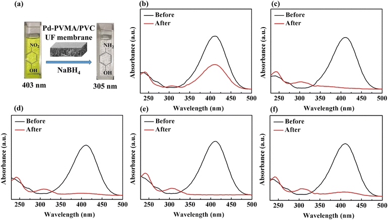 |
| | Fig. 9 Photographs (a) and UV-vis spectra for the degradation of 4-NP by NaBH4 before and after membrane filtration: (b) Pd-PVMA(10%)/PVC, (c) Pd-PVMA(20%)/PVC, (d) Pd-PVMA(30%)/PVC, (e) Pd-PVMA(40%)/PVC, and (f) Pd-PVMA(50%)/PVC. | |
 |
| | Fig. 10 Dye removal efficiency of (a) Pd-PVMA/PVC membranes with different PVMA concentrations, (b) Pd-PVMA(40%)/PVC membrane with different cycles (the 4-NP concentration is 10 ppm), and (c) Pd-PVMA(40%)/PVC membrane with different 4-NP concentrations. | |
The Pd-PVMA(40%)/PVC membranes with high dye removal efficiency and high-water flux were selected for the cycle test, and 4-NP solution (10 mL 10 ppm) was filtered in the presence of NaBH4 at 0.08 MPa five times. The dye removal efficiency is shown in Fig. 10(b). In the first three times, the membrane maintained a removal efficiency of higher than 97.1%, which decreased to 78.2% at the fourth filtration time. The removal efficiency of 4-NP solutions with different concentrations on the Pd-PVMA(40%)/PVC membranes was been studied. When the concentration of the 4-NP solution increased from 10 ppm to 50 ppm, the removal efficiency was still greater than 90%. Fig. S3 (ESI†) shows the standard absorbance curve for the concentration of 4-NP. The concentration of 4-NP in the Pd-PVMA/PVC membrane filtrate was reduced from 10 ppm, 20 ppm, 30 ppm, 40 ppm and 50 ppm to 0.19 ppm, 0.22 ppm, 0.081 ppm, 2.79 ppm and 4.48 ppm, respectively. Tan et al.48 fabricated an MIL-68(Al)/PVDF membrane with the highest 4-NP (10 mg L−1) removal efficiency of 97%. Wu et al.49 successfully prepared a catalytic PVDF membrane integrated with AuNPs through PDA as a spacer for the degradation of 4-NP with more than 90% removal efficiency within 30 min. It can be seen that the Pd-PVMA/PVC membrane with high 4-NP removal efficiency has great advantages in further filtering sewage with a low dye concentration to obtain the filtered water with an ultra-low dye concentration.
Conclusion
The copolymerization of VCM and MALA was conducted in methanol and PVMA copolymer with –COOH and –NH2 was successfully synthesized. By employing PVMA as the modifier of PVC, a Pd-loaded PVMA/PVC UF membrane was prepared, which exhibited great advantages for the removal of dye with high water flux by coupling catalysis and separation processes. The pure water flux of the modified PVC UF membrane with increased hydrophilicity porosity and mean pore size was as high as 691.67 L m−2 h−1. In addition, the method reported herein can be adapted for loading other catalysts for various catalytic UF membranes. Compared with other works, the kinetic constant of the catalytic reaction of the Pd-PVMA/PVC membrane is much higher with a smaller effective area and lower Pd NP loading. At a low operating pressure of 0.08 MPa, the pure water flux of the Pd-PVMA(40%)/PVC membrane reached 208.75 L m−2 h−1 and the removal efficiency was more than 90% for 4-NP solutions at concentrations of 50 ppm or less and more than 97% at a concentration of 10 ppm over three cycles. The content of 4-NP in the wastewater treated using the Pd-PVMA/PVC UF membranes was as low as 0.19 ppm. Thus, the easily prepared Pd-PVMA/PVC UF membrane has potential application in dye wastewater treatment. However, the recycling times of the membrane is not long enough for real industrial application. Thus, further efforts are expected to address this issue, which is under study.
Experimental
Materials and reagents
Vinyl chloride monomer (VCM, 99.99 wt%) was supplied by Dalian Special Gases Co., Ltd. Maleic acid monoamide (MALA, HPLC, 98.0%) and methanol were provided by Aladdin Industrial Corporation. Bis(4-tert-butyl cyclohexyl)peroxydicarbonate (TBCP, 98 wt%) was supplied by J&K Chemical (Beijing, China) and stored in a refrigerator prior to use. PVC (S-70 grade) was used as matrix resin and supplied by Formosa Plastics Co., Ltd, China. Poly(ethylene glycol) 400 (PEG400) and methylene blue were supplied by Sinopharm Chemical Reagent Co., Ltd. N,N-Dimethylacetamide (DMAc) and dimethyl carbonate (DMC) were supplied by FuChen Chemical (Tianjin, China). 4-Nitrophenol (4-NP), palladium acetate (Pd(OAc)2), and sodium borohydride (NaBH4) were provided by Sigma-Aldrich.
Preparation of PVMA
The precipitation polymerization of VCM and MALA was carried out using methanol as the solvent and the procedure was as follows. In a typical run, MALA (1 g, 8.7 mmol), TBCP (0.4 g, 1 mmol), and methanol (39.6 g, 50 mL) were added to a 100 mL reaction kettle. After purging with nitrogen for 10 min, the reactor was frozen in liquid nitrogen and VCM (9 g, 0.14 mol) was charged. After checking for leakage, the reactor was set in a preheated water bath (50 °C) to start the polymerization. At the end of the reaction, the mixture was separated by centrifugation and washed with methanol thrice, and the solid product was dried in a vacuum oven at 50 °C to a constant weight.
Fabrication of PVMA/PVC UF membrane
The PVMA/PVC UF membrane was fabricated by NIPS, which was easy to operate and widely used in preparing membranes with different pore sizes and structures. Briefly, PVMA (0.1 g), PVC (0.4 g) and PEG400 (0.05 g) were dissolved in DMAc (4.0 g), and subsequently heated to 60 °C under stirring for 24 h. Then, the stock solution was settled for 5 h to release bubbles completely. The solution was cast into a film with a thickness of approximately 200 μm on a glass plate. After 30 s for evaporation, the glass plate was immersed in a coagulation bath of deionized water (DI) for 72 h at room temperature to remove the residual solvent and pore-forming agent completely. Finally, the PVMA/PVC UF membrane was obtained.
Fabrication of Pd-loaded PVMA/PVC (Pd-PVMA/PVC) UF membrane
The procedure for the fabrication of the PVMA/PVC UF membrane was similar to that above, except that the amount of DMAc was 3.0 g. Typically, Pd (OAc)2 (0.018 g) was dissolved in DMC (2 g), and then 25% aqueous ethanol (60 mL) was added to prepare the precursor solution. Using DMC as the solvent (a good solvent of Pd(OAc)2 but a poor solvent of PVMA/PVC blend), the deformation of the PVMA/PVC UF membrane was minimized. Then, the PVMA/PVC UF membrane was immersed in the solution to absorb or immobilize Pd2+. After soaking for 5 h, the PVMA/PVC UF membrane was taken out and washed thrice with 25% aqueous ethanol to remove excess Pd(OAc)2. Then, the PVMA/PVC UF membrane was immersed in NaBH4 aqueous solution (100 mL, 0.5 mmol L−1) to reduce Pd2+ for 2 h. Finally, the as-formed Pd-PVMA/PVC was washed with 25% aqueous ethanol three times and dried for 72 h at 50 °C in a vacuum oven.
Material characterization
The conversion of monomers was determined by the gravimetric method. The chemical structure of PVMA was characterized by Fourier transform infrared (FTIR) spectroscopy on a Thermo Nicolet Nexus 670 spectrometer and 1H nuclear magnetic resonance (1H NMR) spectroscopy conducted in dimethyl sulfoxide-d6 (DMSO-d6) on a Bruker Avance 600 spectrometer. The Mn and PDI were analyzed by gel permeation chromatography (GPC) on a Waters 1515 system with Styragel VR HT 3, 4, and 5 columns in series and calibrated with polystyrene standards. The copolymer composition was tested by elemental analysis (EA) with an Elementar UNICUBE instrument and 1H NMR.
PVMA/PVC UF membrane characterization
The mean pore size, cross-sectional and surface morphologies of the membrane were characterized using an S-7800 scanning electron microscope (SEM). The attenuated total reflectance method (ATR, Thermo-Nicolet Nicolet iS50 spectrometer with a 4 cm−1 resolution) was used to characterize the functional groups on the surface of the membrane. X-ray photoelectron spectroscopy (XPS) on a VG Thermo ESCALAB 250XI spectrometer equipped with an Al Kα X-ray radiation source was used to analyze the near-surface compositions. The membrane porosity was measured via the dry–wet weight method. After soaking in DI water for 24 h, the membrane was weighed, and then dried in a vacuum oven at 60 °C for 24 h, before weighing again. The porosity was calculated according to the following equation:| | 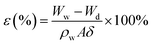 | (2) |
where ε (%) represents the membrane porosity, Ww (g) and Wd (g) are the wet and dry weights, respectively, ρw (g cm−3) is the density of pure water, A (cm2) is area of the membrane and δ (cm) is the thickness of the membrane. The mean pore size (d) was calculated using the Guerout–Elford–Ferry eqn (3):| | 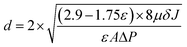 | (3) |
where μ (Pa s) is the pure water viscosity at room temperature, J (L m−2 h) is the pure water flux and ΔP (Pa) is the transmembrane pressure.
The dynamic contact angle (CA) of the membrane was measured using an OCA20 dynamic contact angle instrument. Each membrane was measured 7 times at different locations and the water CAs of each location were continuously recorded for 6 min. The pure water flux (J) was measured using an MSC300 ultrafiltration cup. After compacting for 30 min at 0.15 MPa(G), the membrane was tested at 0.08 MPa(G), and then the value of J was calculated according to eqn (4):
| |  | (4) |
where
J (L m
−2 h) is the pure water flux,
V (L) is the volume of permeated water,
A (m
2) is the membrane effective area and Δ
t (h) is the permeation time.
Pd-PVMA/PVC UF membrane characterization
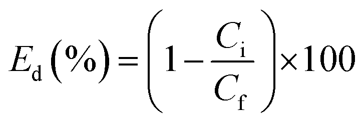
The assay of supported Pd was quantified by inductively coupled plasma optical emission spectrometry (ICP-OES). The pure water flux, J, was measured as before. The catalytic kinetics of the Pd-PVMA/PVC UF membrane was characterized by UV-vis spectroscopy. In a typical process, aqueous dye solution (10 ppm, 10 mM NaBH4) was reduced by the Pd-PVMA/PVC membrane (1 cm × 1 cm) and the UV-vis absorption spectra of the aqueous dye solution were recorded at different times. The procedure to measure the dye removal efficiency was similar to the pure water flux, just replacing the DI water with dye solution and the concentration of the dye recorded by UV-vis absorption spectroscopy. Finally, the dye removal efficiency (Ed) was calculated according to the following equation:| |  | (5) |
where Ci is the initial dye optical absorbance and Cf is the final dye optical absorbance after filtration.
Author contributions
Miss D. Sun: data curation, conceptualization, writing original draft. Dr C. Song: manuscript discussion and revision. Prof. X. Zhang: helping validation and manuscript discussion and revision. Prof. D. Chen: review and revising. Prof. Y. Ma: conceptualization, project administration, supervision, writing – original draft, and investigation. Prof. W. Yang: review and discussion.
Conflicts of interest
There are no conflicts to declare.
Acknowledgements
The work was supported by the National Natural Science Foundation of China (No. 51988102), and Fundamental Research Funds for the Central Universities (XK2020-01).
Notes and references
- W. Jiang, Y. Wu, X. Zhang, D. Chen, Y. Ma and W. Yang, Macromolecules, 2022, 55, 3723–3733 CrossRef CAS.
- W. Ma, M. Sun, D. Huang, C. Chu, T. Hedtke, X. Wang, Y. Zhao, J.-H. Kim and M. Elimelech, Environ. Sci. Technol., 2022, 56, 8733–8745 CrossRef CAS PubMed.
- I. Sadeghi, E. Y. Liu, H. Yi and A. Asatekin, ACS Appl. Nano Mater., 2019, 2, 5233–5244 CrossRef CAS.
- R. Huang, H. Zhu, R. Su, W. Qi and Z. He, Environ. Sci. Technol., 2016, 50, 11263–11273 CrossRef CAS PubMed.
- M. Hong, B. Wang, X. Xu, P. Bin, J. Zhang and Q. Zhang, J. Membr. Sci., 2022, 662, 121002 CrossRef CAS.
- Y.-X. Wang, S. Ma, M.-N. Huang, H. Yang, Z.-L. Xu and Z. Xu, Sep. Purif. Technol., 2019, 227, 115700 CrossRef CAS.
- M. Gopiraman, D. Deng, S. Saravanamoorthy, I.-M. Chung and I. S. Kim, RSC Adv., 2018, 8, 3014–3023 RSC.
- X. Wu, K. Rigby, D. Huang, T. Hedtke, X. Wang, M. W. Chung, S. Weon, E. Stavitski and J.-H. Kim, Environ. Sci. Technol., 2022, 56, 1341–1351 CrossRef CAS PubMed.
- X. Zhu, Z. Pan, H. Jiang, Y. Du and R. Chen, Sep. Purif. Technol., 2021, 279, 119731 CrossRef CAS.
- N. Jadbabaei, R. J. Slobodjian, D. Shuai and H. Zhang, Appl. Catal., A, 2017, 543, 209–217 CrossRef CAS.
- H. Gholami Derami, P. Gupta, R. Gupta, P. Rathi, J. J. Morrissey and S. Singamaneni, ACS Appl. Nano Mater., 2020, 3, 5437–5448 CrossRef CAS.
- J. Zhu, Y. Su, X. Zhao, Y. Li, J. Zhao, X. Fan and Z. Jiang, Ind. Eng. Chem. Res., 2014, 53, 14046–14055 CrossRef CAS.
- C. Wu, Z. Wang, S. Liu, Z. Xie, H. Chen and X. Lu, J. Membr. Sci., 2018, 548, 50–58 CrossRef CAS.
- Z.-Y. Ma, Y.-R. Xue, H.-C. Yang, J. Wu and Z.-K. Xu, Macromolecules, 2022, 55, 3363–3383 CrossRef CAS.
- G. Peng, W. Yaoqin, S. Changmei, J. Chunnuan, Z. Ying, Q. Rongjun and W. Ying, J. Membr. Sci., 2022, 642, 119993 CrossRef CAS.
- A. Behboudi, Y. Jafarzadeh and R. Yegani, J. Membr. Sci., 2017, 534, 18–24 CrossRef CAS.
- M. Yong, Y. Zhang, S. Sun and W. Liu, J. Membr. Sci., 2019, 575, 50–59 CrossRef CAS.
- Y. Peng and Y. Sui, Desalination, 2006, 196, 13–21 CrossRef CAS.
- P. R. Babu and V. G. Gaikar, J. Appl. Polym. Sci., 1999, 73, 1117–1130 CrossRef CAS.
- Q. Alsalhy, A. Merza, K. Rashid, A. Adam, A. Figoli, S. Simone and E. Drioli, J. Appl. Polym. Sci., 2013, 130, 989–1004 CrossRef CAS.
- A. Jalal Sadiq, K. M. Shabeeb, B. I. Khalil and Q. F. Alsalhy, Chem. Eng. Commun., 2019, 207, 733–750 CrossRef.
- S. Saberi, A. A. Shamsabadi, M. Shahrooz, M. Sadeghi and M. Soroush, ACS Omega, 2018, 3, 17439–17446 CrossRef CAS PubMed.
- F. H. Al-Ani, Q. F. Alsalhy, R. S. Raheem, K. T. Rashid and A. Figoli, Membranes, 2020, 10, 77 CrossRef CAS PubMed.
- T. Ahmad and C. Guria, J. Water Process. Eng., 2022, 45, 102466 CrossRef.
- A. Masoumi, M. Ghaemy and A. N. Bakht, Ind. Eng. Chem. Res., 2014, 53, 8188–8197 CrossRef CAS.
- S. Saber-Samandari, M. Gazi and O. Yilmaz, Water, Air, Soil Pollut., 2013, 224, 1624 CrossRef.
- N. Wu and Z. Li, Chem. Eng. J., 2013, 215–216, 894–902 CrossRef CAS.
- X. Guo, Y. Ma, D. Chen, W. Peng and W. Yang, J. Macromol. Sci., Part A: Pure Appl. Chem., 2012, 49, 1061–1069 CrossRef CAS.
- W. Jiang, X. Zhang, D. Chen, Y. Ma and W. Yang, Ind. Eng. Chem. Res., 2019, 59, 783–792 CrossRef.
- Z. Liu, D. Chen, J. Zhang, H. Liao, Y. Chen, Y. Sun, J. Deng and W. Yang, Research, 2018, 2018, 9370490 CrossRef PubMed.
- Y. Wang, D. Chen, G. Wang, C. Zhao, Y. Ma and W. Yang, Chem. Eng. J., 2018, 336, 152–159 CrossRef CAS.
- C. Zhang, D. Chen and W. Yang, Ind. Eng. Chem. Res., 2020, 59, 15087–15097 CrossRef CAS.
- P. Cui, C.-T. Song, X.-H. Zhang, D. Chen, Y.-H. Ma and W.-T. Yang, Chin. J. Polym. Sci., 2019, 37, 646–653 CrossRef CAS.
- J. Liu, Y. Su, J. Peng, X. Zhao, Y. Zhang, Y. Dong and Z. Jiang, Ind. Eng. Chem. Res., 2012, 51, 8308–8314 CrossRef CAS.
- Z. Dong, X. Le, X. Li, W. Zhang, C. Dong and J. Ma, Appl. Catal., B, 2014, 158–159, 129–135 CrossRef CAS.
- M. Maniyazagan, P. Naveenkumar, H.-W. Yang, H. Zuhaib, W. Seung Kang and S.-J. Kim, J. Mol. Liq., 2022, 365, 120123 CrossRef CAS.
- S. J. Lee, Y. Yu, H. J. Jung, S. S. Naik, S. Yeon and M. Y. Choi, Chemosphere, 2021, 262, 128358 CrossRef CAS PubMed.
- Y. M. Hunge, A. A. Yadav, S. W. Kang, H. Kim, A. Fujishima and C. Terashima, J. Hazard. Mater., 2021, 419, 126453 CrossRef CAS PubMed.
- H. Zhang, S. Gao, N. Shang, C. Wang and Z. Wang, RSC Adv., 2014, 4, 31328–31332 RSC.
- H. Zhang, Y. Zhao, W. Liu, S. Gao, N. Shang, C. Wang and Z. Wang, Catal. Commun., 2015, 59, 161–165 CrossRef CAS.
- W. Dong, S. Cheng, C. Feng, N. Shang, S. Gao and C. Wang, Catal. Commun., 2017, 90, 70–74 CrossRef CAS.
- L. Zhang, N. Shang, S. Gao, J. Wang, T. Meng, C. Du, T. Shen, J. Huang, Q. Wu, H. Wang, Y. Qiao, C. Wang, Y. Gao and Z. Wang, ACS Catal., 2020, 10, 8672–8682 CrossRef CAS.
- L. Rao, X. You, B. Chen, L. Shen, Y. Xu, M. Zhang, H. Hong, R. Li and H. Lin, Chemosphere, 2022, 288, 132490 CrossRef CAS PubMed.
- Y. Wang, G.-E. Chen, H.-L. Wu, Z.-L. Xu, J.-J. Wan, L.-J. Liu, S.-J. Xu, Y.-F. Kong, Q. Wu, J. Min and H.-F. Mao, Sep. Purif. Technol., 2020, 235, 116143 CrossRef CAS.
- X.-Q. Zhang, R.-F. Shen, X.-J. Guo, X. Yan, Y. Chen, J.-T. Hu and W.-Z. Lang, Chem. Eng. J., 2021, 408, 128018 CrossRef CAS.
- L. Xu, S. Ma, X. Chen, C. Zhao, Y. Zhao and L. Chen, Polym. Eng. Sci., 2018, 58, 150–159 CrossRef CAS.
- X. Fang, J. Li, B. Ren, Y. Huang, D. Wang, Z. Liao, Q. Li, L. Wang and D. D. Dionysiou, J. Membr. Sci., 2019, 579, 190–198 CrossRef CAS.
- Y. Tan, Z. Sun, H. Meng, Y. Han, J. Wu, J. Xu, Y. Xu and X. Zhang, Sep. Purif. Technol., 2019, 215, 217–226 CrossRef CAS.
- Z. Wu, H. Lin, Y. Wang, X. Yu, J. Li, Z. Xiong, Y. Wang, Y. Huang, T. Chen and F. Liu, RSC Adv., 2016, 6, 62302–62309 RSC.
|
| This journal is © The Royal Society of Chemistry 2023 |
Click here to see how this site uses Cookies. View our privacy policy here. 
 Open Access Article
 This Open Access Article is licensed under a Creative Commons Attribution-Non Commercial 3.0 Unported Licence
 ab,
Yuhong
Ma
ab,
Yuhong
Ma