 Open Access Article
Yolk–shelled LiNi0.6Co0.2Mn0.2O2 cathode for high-performance lithium ion batteries: a general synthetic strategy†
Ang
Gao
,
Tianhao
Yao
,
Menglong
Yao
,
Ruochen
Chen
,
Qiangrui
He
and
Hongkang
Wang
 *
*
State Key Lab of Electrical Insulation and Power Equipment, Center of Nanomaterials for Renewable Energy (CNRE), School of Electrical Engineering, Xi’an Jiaotong University, Xi’an 710049, P. R. China. E-mail: hongkang.wang@mail.xjtu.edu.cn
First published on 23rd November 2022
Abstract
By virtue of complexing Ni/Co/Mn ions with glucose under solvothermal conditions, well-defined spherical Ni/Co/Mn-gluconate with tunable size and elemental composition is prepared and readily converted into yolk–shelled Li(NixCoyMn1−x−y)O2. As an example, a yolk–shelled LiNi0.6Co0.2Mn0.2O2 cathode is prepared and demonstrates high specific lithium storage capacity and excellent cycling stability.
Lithium ion batteries (LIBs) have been widely used in portable electronics, electric vehicles and the emerging smart grid, owing to their greenness, high energy density, long cycle life and small memory effect.1–5 As a key component of LIBs, cathode materials not only affect the energy density but also the safety, which generally cannot be combined in one material.6 For example, the LiFePO4 cathode shows high safety but low energy density and poor conductivity,7 while the initially commercialized LiCoO2 cathode adopts the expensive and toxic element cobalt and also suffers from a decline in electrochemical performance and safety problems when it is overcharged.8 Alternatively, layered ternary cathodes with the formula Li(NixCoyMn1−x−y)O2 (denoted as NCM) have received considerable attention owing to their high energy density, enhanced safety, low cost and good cycling stability.9,10
Rational structural design of NCM cathode materials with well-defined sizes, shapes and compositions is crucial to improve their electrochemical properties. In particular, the yolk–shell structure would offer more electrochemical active sites and facilitate the electrolyte penetration, thereby shortening the ion diffusion path. Furthermore, the yolk–shell structure can accommodate the volume variations upon charge/discharge cycling, facilitating enhancement of the long-term cycling stability. Additionally, the synthetic strategy is critically important, and to date, various routes have been developed to tune and fabricate NCM cathodes, such as the high-temperature solid phase method,9 co-precipitation method, sol–gel method, hydrothermal method and spray-drying method.11 At present, the most widely and commercially used method is the co-precipitation method, which shows many advantages, such as uniform morphology and narrow particle size distribution of the precursors, as these microstructures can be readily controlled by adjusting the reaction parameters.12,13 However, the co-precipitation method usually involves complicated control of parameters and lengthy production processes, such as the use of complexing and precipitation agents, pH value, temperature, time, and so on, which generally produce the secondary spherical particles in morphology with inferior uniformity of the elemental distribution.
As a typical ternary cathode, LiNi0.6Co0.2Mn0.2O2 (NCM622) is promising because of its better stability, lower cost and higher capacity, but its performance is greatly affected by the synthetic route.14,15 For example, Yue et al. investigated the effect of synthesis routes on the electrochemical performance of NCM622 prepared by either a spray-drying method or solid-state method, both of which produced irregular NCM622 particles; the superior particles prepared by spray-drying method delivered a first discharge capacity of 143.7 mA h g−1 with a capacity retention of 84.5% after 50 cycles at 160 mA g−1.9 It is noteworthy that these methods are not suitable for delicate structure engineering. Hence, it is still challenging to explore efficient synthesis methods to produce well-defined NCM cathodes with fine microstructures.
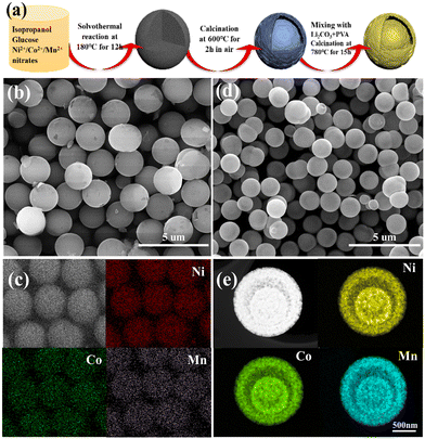
Herein, we report a universal method to prepare yolk–shelled NCM cathodes with a spherical morphology using well-defined Ni/Co/Mn-gluconate spheres as precursors, which were prepared by complexing Ni/Co/Mn ions with glucose under solvothermal conditions. Note that the content as well as the combination of Ni/Co/Mn ions can be readily tuned, which can be used to fabricate a wide range of cathode materials with one, two and or three transition metal ions. As an example, yolk–shelled LiNi0.6Co0.2Mn0.2O2 (NCM622) spheres were successfully synthesized; the scheme for their fabrication is shown in Fig. 1a. Firstly, glucose was used as a complexing agent; it can readily and fully coordinate with the Ni2+/Co2+/Mn2+ ions during the solvothermal reaction process to form Ni/Co/Mn-gluconate microspheres with a uniform size of around 2 μm (Fig. 1b), in which the elements Ni, Co and Mn are uniformly distributed within the microspheres (Fig. 1c), suggesting the successful complexing of the Ni2+/Co2+/Mn2+ ions with the hydroxyl groups of the glucose. Up annealing in air at 600 °C, the solid Ni/Co/Mn-gluconate microspheres convert into yolk–shelled NiCoMn oxide (NCMO) microspheres with a conformal morphology but reduced size of around 1.25 μm (Fig. 1d). During annealing of the spherical Ni/Co/Mn-gluconate precursor, the temperature difference within the particles would affect their decomposition rate; namely, the outer region first forms a stable oxide shell, while the inner parts start to decompose and contract, thus forming a gap between the outer and inner parts. Fig. 1e shows the high-angle annular dark-field scanning transmission electron microscopy (HAADF STEM) image of a single NCMO microsphere, which clearly reveals the yolk–shell structure and shows that the elements Ni/Co/Mn are well distributed within the inner core and the outer shell. Fig. S1 (ESI†) shows the XRD pattern of the NCMO, in which the main peaks at 37.4° and 43.5° match well with NiO (JCPDS no. 73-1519), while the peaks at 36.1° can be indexed to the cobalt manganese oxide.
The yolk–shelled NCM622 was prepared by solid-state reaction of a NCMO-Li2CO3 mixture with poly(vinyl alcohol) (PVA) as a morphology-maintaining agent. Fig. 2a shows the SEM image of NCM622 (NCM622-P2-780), which mostly inherits the shape of the NCMO precursor but with irregular particles, even though the shrinkage and deformation of the particle shape are caused during calcination, which may be due to the uneven solid-state reaction between the precursor and the lithium salt under the high sintering temperature.16 The effects of the addition/amount of PVA and sintering temperature were also investigated, as they can affect the crystal growth as well as the morphology of the as-prepared NCM622 to some extent. Fig. 2b shows the transmission electron microscopy (TEM) image of NCM622, which displays the yolk–shell structure, although some irregular particles are attached nearby. In the high-resolution TEM (HRTEM) image of NCM622 (Fig. 2c), the well-defined lattice fringes with a d-spacing of 0.475 nm can be indexed to the (003) crystal plane of layered LiMO2.17,18Fig. 2d shows the HAADF STEM image of a single NCM622 sphere with the corresponding energy dispersive spectrometer (EDS) maps, which apparently display the yolk–shell structure with the elements Ni, Co and Mn evenly distributed within the yolk–shell sphere. Inductively coupled plasma (ICP) analysis, which is shown in Table S1 (ESI†), reveals that the proportion of Ni:Co:Mn is close to 6![[thin space (1/6-em)]](https://www.rsc.org/images/entities/char_2009.gif) :
:![[thin space (1/6-em)]](https://www.rsc.org/images/entities/char_2009.gif) 2
2![[thin space (1/6-em)]](https://www.rsc.org/images/entities/char_2009.gif) :
:![[thin space (1/6-em)]](https://www.rsc.org/images/entities/char_2009.gif) 2.
2.
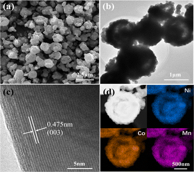 | ||
| Fig. 2 (a) SEM, (b) TEM and (c) HRTEM images of the NCM622 cathode, and (d) HAADF STEM image of a single NCM622 yolk–shell sphere with corresponding EDS maps of the elements Ni, Co and Mn. | ||
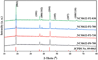
Fig. 3 shows the X-ray diffraction (XRD) patterns of NCM622 prepared using different annealing temperatures as well as different amounts of PVA, in which all the diffraction peaks can be well ascribed to the hexagonal α-NaFeO2 structure with the R![[3 with combining macron]](https://www.rsc.org/images/entities/char_0033_0304.gif) m space group,19 and the sharp peaks suggest the high crystallinity of the as-prepared NCM622. The splitting peaks of (006)/(102) and (108)/(110) are obvious, suggesting the ordered layered hexagonal structure.20,21 Note that the c/a and I(003)/I(104) ratios of the products represent the ordering of the layered structure and the mixing degree of the cations (Li+ and Ni2+).22 A higher c/a value represents higher ordering of the layered structure, while a higher I(003)/I(104) value indicates lower cation mixing. Table S2 (ESI†) summarizes the lattice parameters of the different NCM622 products, and NCM622-P2-780 shows the highest c/a value of 4.92 and I(003)/I(104) of 1.81, suggesting the better crystal structure for lithium storage.
m space group,19 and the sharp peaks suggest the high crystallinity of the as-prepared NCM622. The splitting peaks of (006)/(102) and (108)/(110) are obvious, suggesting the ordered layered hexagonal structure.20,21 Note that the c/a and I(003)/I(104) ratios of the products represent the ordering of the layered structure and the mixing degree of the cations (Li+ and Ni2+).22 A higher c/a value represents higher ordering of the layered structure, while a higher I(003)/I(104) value indicates lower cation mixing. Table S2 (ESI†) summarizes the lattice parameters of the different NCM622 products, and NCM622-P2-780 shows the highest c/a value of 4.92 and I(003)/I(104) of 1.81, suggesting the better crystal structure for lithium storage.
X-ray photoelectron spectroscopy (XPS) was used to determine the oxidation states of Ni/Co/Mn in the different NCM622 products. Fig. 4a shows the Ni2p XPS spectrum, in which the two prominent peaks at 855.7 eV and 873.4 eV relate to Ni2p3/2 and Ni2p1/2 with two satellite peaks at 861.6 eV and 880.1 eV, respectively.23,24 The Ni2p3/2 peak can be fitted into two peaks at 854.4 eV and 855.8 eV, which can be assigned to Ni2+ and Ni3+, respectively.25,26 Note that the capacity contribution of NCM622 mainly depends on the oxidation–reduction of Ni ions, so that the ratio Ni3+/(Ni2+ + Ni3+) determines the specific capacity. As shown in Fig. S2 (ESI†), it can be seen that the value of Ni3+/(Ni2+ + Ni3+) shows an “increase-to-decrease” as the temperature rises. Apparently, NCM622-P2-780 displays the largest Ni3+/(Ni2+ + Ni3+) ratio of 78.01%, which could deliver higher specific capacity.27 The sintering temperature would lead to more complete oxidation of Ni2+; however, once the sintering temperature reaches a certain value, the layered structure would be destroyed, and the Ni2+ would no longer be oxidized to more Ni3+, which also makes the cation mixing in the layered structure more serious. In the Co2p XPS spectrum (Fig. 4b), the two peaks at 780.5 eV and 795.6 eV correspond to the Co2p3/2 and Co2p1/2 of Co3+, respectively.28,29Fig. 4c shows the Mn2p XPS spectrum, in which the two main peaks at 642.5 and 654.1 eV correspond to Mn2p3/2 and Mn2p1/2, respectively.25,30 Moreover, another minor peak at 638.1 eV can be attributed to Mn2+. The O1 s XPS spectrum in Fig. 4d, shows two different peaks at 531.5 and 529.3 eV, relating to the reactive oxygen species and lattice oxygen, respectively.29 The higher intensity of the peak at 531.5 eV is due to the residual Li2CO3 at the surface, which would absorb water when exposed to air.31,32
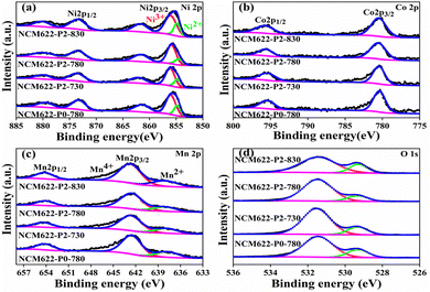 | ||
| Fig. 4 XPS spectra of (a) Ni 2p, (b) Co 2p, (c) Mn 2p and (d) O 1s for the different NCM622 cathodes. | ||
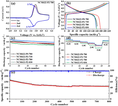
Fig. 5a shows the cyclic voltammetry (CV) curves of NCM622-P2-780 at 0.1 mV s−1 in the voltage range of 2.8–4.3V, which show a pair of broad cathodic/anodic peaks corresponding to the redox reaction of Ni2+/Ni4+.33–35 The peak position difference of the redox peak represents the polarization upon lithiation/delithiation.36 Fig. S3 (ESI†) shows the CV curves of different NCM622 cathodes with the insets showing the redox peak positions as well as the excellent gap. Apparently, NCM622-P2-780 displays a low polarization of 26 mV, indicating its excellent structural stability upon lithium insertion/extraction.37Fig. 5b shows the initial charge and discharge curves of NCM622-P0-780, NCM622-P2-730, NCM622-P2-780 and NCM622-P2-780 at 200 mA g−1 (1 C), and the discharge capacities are 163.1, 158.2, 177.4 and 157.3 mA h g−1, with initial coulomb efficiencies of 82.2%, 74.5%, 85.7% and 81.1% respectively. The capacity loss could be due to the irreversible side reaction between the electrolyte and the electrode surface and the formation of a cathode electrolyte interface (CEI) film. After 100 cycles at 1C, these electrodes still maintain high reversible capacities of 141.9, 148.3, 156.7 and 135.6 mA h g−1 after 100 cycles, respectively, with corresponding capacity retentions of 87%, 93.7%, 88.3% and 86.2% (Fig. 5c). Overall, the NCM622-P2-780 electrode displays the highest initial coulomb efficiency and good capacity retention, which is outstanding as compared with the previously reported NCM622 cathodes (Table S3, ESI†). The superior electrochemical performance of the yolk–shelled NCM622-P2-780 can be attributed to its favorable crystal structure, which not only facilitates ion diffusion and provides more active sites, but also efficiently buffers the volume changes upon lithiation/delithiation cycling.
Fig. 5d shows the rate performance of the different NCM622 electrodes at different current densities ranging from 0.2C to 5.0C. The NCM622-P2-780 electrode demonstrates the best rate capability with high and stable capacities of 179.5, 169.3, 161.5 and 151.4 mA h g−1 at 0.2C, 0.5C, 1C, 2C and 5C, respectively. Fig. 5e shows the long-term cycling performance of NCM622-P2-780 at 1C; it delivers a high reversible capacity of around 110 mA h g−1 after 800 cycles, with a high capacity retention of 75.5%. Electrochemical impedance spectroscopy (EIS) was used to study the reaction kinetics of the different NCM622 electrodes, as shown in Fig. S4 (ESI†). The semicircles in the high frequency region and the sloping lines in the low frequency region represent the charge transfer impedance (Rct) and the lithium ion diffusion resistance, respectively.32,38 It is noteworthy that the charge transfer impedances are 47.98, 42.98, 44.82 and 44.87 Ω for NCM622-P0-780, NCM622-P2-730, NCM622-P2-780 and NCM622-P2-830, respectively, indicating fast charge transfer rates. Moreover, all these cathodes show steep sloping lines, suggesting a high lithium ion diffusion rate. In contrast, NCM622-P2-830 displays a less-steep line, which may be due to the fact that the higher annealing temperature would destroy the core–shell structure, thus hindering the faster ion diffusion.
To demonstrate the efficacy of the complexing effect of the Ni/Co/Mn ions with glucose, various NCM cathodes (ex., NCM111, NCM523, NCM811) were also prepared by simply changing the contents of the Ni/Co/Mn ions. Fig. S5 (ESI†) shows the different Ni/Co/Mn-gluconates and their derived oxides with well-defined spherical morphology, which can also be converted into core–shelled NCM111, NCM523 and NCM811 cathodes, as revealed by HAADF STEM images and EDS mapping (Fig. S5, ESI†). Fig. S6 (ESI†) reveals that all these products have a layered hexagonal structure. Fig. S7 (ESI†) compares their cycling performance at 1C, revealing that the specific capacity of the NCM cathodes can be enhanced by increasing the Ni content, but they show relatively worse cycling stability. Interestingly, NCM111 displayed excellent cycling stability, delivering a reversible capacity of 120 mA h g−1 with a capacity retention of 94% after 100 cycles at 1C. In addition, it is noteworthy that LiCoO2 can also be prepared (Fig. S8, ESI†), further demonstrating the universality of the current synthetic route for developing various cathode materials for LIBs.
In summary, we demonstrated the general fabrication of core–shelled ternary Li(NixCoyMn1−x−y)O2 cathode materials using solid Ni/Co/Mn-gluconate spheres as precursors, which were prepared by complexing Ni/Co/Mn ions with glucose under solvothermal conditions. In the case of NCM622, the effects of PVA and the sintering temperature on the morphology, properties and structure were studied. When examined as a cathode for LIBs, the optimized NCM622 electrode demonstrated excellent electrochemical performance, delivering a high initial reversible capacity of 177.4 mA h g−1 and a specific capacity of 110.0 mA h g−1 after long-term cycling for 800 cycles at 1C. Most importantly, we reported a general strategy to fabricate core–shell cathode materials for LIBs via the complexing of transition metal ions with glucose under solvothermal conditions.
Conflicts of interest
There are no conflicts to declare.Acknowledgements
This work was supported by the National Natural Science Foundation of China (Grant No. 52077175).Notes and references
- J. B. Goodenough, Energy Environ. Sci., 2014, 7, 14–18 RSC
.
- Z. Li, Z. Shi, X. Liu and Z. Shi, Pattern Recogn. Lett., 2011, 32, 516–523 CrossRef
.
- R. Zhu, H. Duan, Z. Zhao and H. Pang, J. Mater. Chem. A, 2021, 9, 9535–9572 RSC
.
- Y. Fang, X.-Y. Yu and X. W. Lou, Angew. Chem., Int. Ed., 2017, 56, 5801–5805 CrossRef CAS PubMed
.
- Y. Fang, X.-Y. Yu and X. W. Lou, Matter, 2019, 1, 90–114 CrossRef
.
- A. W. Golubkov, D. Fuchs, J. Wagner, H. Wiltsche, C. Stangl, G. Fauler, G. Voitic, A. Thaler and V. Hacker, RSC Adv., 2014, 4, 3633–3642 RSC
.
- T. Kobayashi, N. Kawasaki, Y. Kobayashi, K. Shono, Y. Mita and H. Miyashiro, J. Power Sources, 2014, 245, 1–6 CrossRef CAS
.
- Y. Chen, G. X. Wang, K. Konstantinov, H. K. Liu and S. X. Dou, J. Power Sources, 2003, 119–121, 184–188 CrossRef CAS
.
- P. Yue, Z. Wang, H. Guo, F. Wu, Z. He and X. Li, J. Solid State Electrochem., 2012, 16, 3849–3854 CrossRef CAS
.
- Z. Chen, D. Chao, M. Chen and Z. Shen, RSC Adv., 2020, 10, 18776–18783 RSC
.
- Y. Ma, L. Li, L. Wang, R. Luo, S. Xu, F. Wu and R. Chen, J. Alloys Compd., 2019, 778, 643–651 CrossRef CAS
.
- Y.-S. He, Z.-F. Ma, X.-Z. Liao and Y. Jiang, J. Power Sources, 2007, 163, 1053–1058 CrossRef CAS
.
- Y. Wang, H. Hao, S. Hwang, P. Liu, Y. Xu, J. A. Boscoboinik, D. Datta and D. Mitlin, J. Mater. Chem. A, 2021, 9, 18582–18593 RSC
.
- R. Santhanam and B. Rambabu, J. Power Sources, 2010, 195, 4313–4317 CrossRef CAS
.
- L. Wang, B. Wu, D. Mu, X. Liu, Y. Peng, H. Xu, Q. Liu, L. Gai and F. Wu, J. Alloys Compd., 2016, 674, 360–367 CrossRef CAS
.
- J. Zheng, P. Yan, L. Estevez, C. Wang and J.-G. Zhang, Nano Energy, 2018, 49, 538–548 CrossRef CAS
.
- W. Hua, Z. Wu, M. Chen, M. Knapp, X. Guo, S. Indris, J. R. Binder, N. N. Bramnik, B. Zhong, H. Guo, S. Chou, Y.-M. Kang and H. Ehrenberg, J. Mater. Chem. A, 2017, 5, 25391–25400 RSC
.
- Y. Fang, S. L. Zhang, Z.-P. Wu, D. Luan and X. W. Lou, Sci. Adv., 2021, 7(21), eabg3626 CrossRef CAS PubMed
.
- S. C. Yin, Y. H. Rho, I. Swainson and L. F. Nazar, Chem. Mater., 2006, 18, 1901–1910 CrossRef CAS
.
- Z.-D. Huang, X.-M. Liu, S.-W. Oh, B. Zhang, P.-C. Ma and J.-K. Kim, J. Mater.
Chem., 2011, 21, 10777–10784 RSC
.
- A. M. A. Hashem, A. E. Abdel-Ghany, A. E. Eid, J. Trottier, K. Zaghib, A. Mauger and C. M. Julien, J. Power Sources, 2011, 196, 8632–8637 CrossRef CAS
.
- J. Dou, X. Kang, T. Wumaier, H. Yu, N. Hua, Y. Han and G. Xu, J. Solid State Electrochem., 2012, 16, 1481–1486 CrossRef CAS
.
- N. V. Kosova, E. T. Devyatkina and V. V. Kaichev, J. Power Sources, 2007, 174, 965–969 CrossRef CAS
.
- H. Zhu, T. Xie, Z. Chen, L. Li, M. Xu, W. Wang, Y. Lai and J. Li, Electrochim. Acta, 2014, 135, 77–85 CrossRef CAS
.
- S. Gopukumar, K. Y. Chung and K. B. Kim, Electrochim. Acta, 2004, 49, 803–810 CrossRef CAS
.
- J. Li, S. Xiong, Y. Liu, Z. Ju and Y. Qian, Nano Energy, 2013, 2, 1249–1260 CrossRef CAS
.
- W. Ahn, S. N. Lim, K.-N. Jung, S.-H. Yeon, K.-B. Kim, H. S. Song and K.-H. Shin, J. Alloys Compd., 2014, 609, 143–149 CrossRef CAS
.
- V. R. Galakhov, E. Z. Kurmaev, S. Uhlenbrock, M. Neumann, D. G. Kellerman and V. S. Gorshkov, Solid State Commun., 1996, 99, 221–224 CrossRef CAS
.
- K. M. Shaju, G. V. Subba Rao and B. V. R. Chowdari, Solid State Ionics, 2002, 152–153, 69–81 CrossRef CAS
.
- S. H. Kang, J. Kim, M. E. Stoll, D. Abraham, Y. K. Sun and K. Amine, J. Power Sources, 2002, 112, 41–48 CrossRef CAS
.
- J. Gurgul, M. T. Rinke, I. Schellenberg and R. Pöttgen, Solid State Scid, 2013, 17, 122–127 CrossRef CAS
.
- S. Yoon, K.-N. Jung, S.-H. Yeon, C. S. Jin and K.-H. Shin, J. Electroanal. Chem., 2012, 683, 88–93 CrossRef CAS
.
- A. V. Murugan, T. Muraliganth and A. Manthiram, J. Phys. Chem. C, 2008, 112, 14665–14671 CrossRef CAS
.
- H.-H. Sun, W. Choi, J. K. Lee, I.-H. Oh and H.-G. Jung, J. Power Sources, 2015, 275, 877–883 CrossRef CAS
.
- L. Liang, K. Du, Z. Peng, Y. Cao, J. Duan, J. Jiang and G. Hu, Electrochim. Acta, 2014, 130, 82–89 CrossRef CAS
.
- J. Zhang, Z. Yang, R. Gao, L. Gu, Z. Hu and X. Liu, ACS Appl. Mater. Interf., 2017, 9, 29794–29803 CrossRef CAS PubMed
.
- R. Zhao, Z. Yang, J. Chen, Z. Chen, J. Liang and H. Chen, J. Alloys Compd., 2015, 627, 206–210 CrossRef CAS
.
- S. Lee and S. S. Park, J. Phys. Chem. C, 2012, 116, 6484–6489 CrossRef CAS
.
Footnote |
| † Electronic supplementary information (ESI) available. See DOI: https://doi.org/10.1039/d2ma00943a |
| This journal is © The Royal Society of Chemistry 2023 |

