DOI:
10.1039/D2MA00916A
(Paper)
Mater. Adv., 2023,
4, 1081-1088
Enhanced photocatalytic activity of CoNi-decorated Zn-doped Cu2O synthesized by electrodeposition technique
Received
20th September 2022
, Accepted 4th January 2023
First published on 10th January 2023
Abstract
Cu2O is known as a potential photocatalyst that functions in the visible light region due to its narrow bandgap energy. In this study, to improve photocatalytic activity and photostability, Zn-doped Cu2O was decorated with CoNi cocatalyst using an electrodeposition technique at different deposition times. Photocatalytic activity of the CoNi-decorated Zn-doped Cu2O was investigated in the degradation of methylene blue (MB) dye, which is known as a toxic, mutagenic, and carcinogenic synthetic dye. The CoNi cocatalyst was found to effectively increase the photoelectrochemical properties and photocatalytic activity of Zn-doped Cu2O. Electrochemical impedance spectroscopy measurements show that by growing CoNi, the charge transfer resistance of the Zn-doped Cu2O decreased from 3.23 kΩ to 1.11 kΩ. A high photocurrent, measured under simulated solar irradiation using a linear sweep voltammetry technique, of 25.43 mA cm−2 was obtained with a CoNi deposition time of 150 s. The CoNi-decorated Zn-doped Cu2O demonstrated a high photostability and photocatalytic activity, as shown by the increase of MB photodegradation from 26.03% to 71.55%. The growth of CoNi cocatalyst is believed to have enhanced carrier concentration, charge transfer, and charge carrier lifetime, thus increasing the photocatalytic activity of the Zn-doped Cu2O.
Introduction
Deposition of metal cocatalysts on photocatalytic materials is interesting because it is a relatively simple and effective technique to enhance photodegradation of synthetic dyes, such as methylene blue (MB), which is commonly used in dyeing cotton, wool, and silk. This dye is not biodegradable and is known to be toxic, mutagenic, and carcinogenic.1 Dye photodegradation has been previously reported using different photocatalyst materials, for example Fe2O3, SnO2, WO3, ZnO, and TiO2. However, Fe2O3,2 SnO2,3 and WO34 have conduction band edges lower than the reversible hydrogen potential. Therefore, they require external electrical voltage to facilitate reaction on the cathode. On the other hand, ZnO5,6 and TiO27,8 possess large band gap energies, making them suitable only for working in the UV region. The spectrum of sunlight is comprised of 5–7% UV rays, 47% visible rays, and 46% infrared rays. Moreover, ZnO also shows limitations in catalyzing reactions in aqueous solution, since it is easily subjected to corrosion under light and forms Zn(OH)2 on the ZnO surface, resulting in catalyst passivation over time.9 Compared to those photocatalysts, Cu2O has a band gap energy of 2.18 eV,10 which is close to the ideal photocatalyst, because it efficiently works in visible regions to absorb more photons that can induce redox reactions.11–13 To reduce the photoelectron and hole pair recombination that occurs due to its narrow band gap energy, Cu2O can be doped by Zn element, which also increases charge transfer efficiency.14,15 Although Cu2O demonstrates intrinsic characteristics that are suitable for a photocatalyst material, this semiconductor is susceptible to photocorrosion, which limits its practical application.16 Nevertheless, Cu2O exhibits inefficient electron transfer due to improper band bending.17
Loading proper metal cocatalysts on a semiconductor surface is known as a practical approach to improve catalytic activity by providing active sites that can accelerate the catalytic reaction. Likewise, the presence of a cocatalyst can be expected to prevent corrosion on the photocatalyst surface. Among metal cocatalysts, cobalt (Co) and nickel (Ni) are considered as cost-effective elements compared to precious metals such as palladium (Pd), rhodium (Rh), gold (Au), and platinum (Pt). The electrochemical properties of photocatalytic Cu2O coated with Co,18 CoP,19 CoPi,20 Co3O4,21 NiS,22 Ni(OH)2,23 Ni,24 and NiFe25 have been reported. These Co-based cocatalysts could stabilize and improve the photocurrent of Cu2O by increasing active sites and inhibiting electron–hole pair recombination.20,26 On the other hand, Ni-based cocatalysts show a synergistic effect with Cu2O, increasing the photocurrent stability and catalytic activity of Cu2O to efficiently and rapidly instigate load separation.27 Therefore, it is possible that the synergistic effect between Co and Ni can improve the electrochemical properties and stability of Zn-doped Cu2O.
To directly decorate a semiconductor with cocatalysts, electrodeposition, including pulsed potential28,29 or constant-potential and -current method,30–32 is known as a useful approach to control sample features.33 This technique has been successfully employed to facilitate the deposition of CoNi,34 NiFe,35 ZnCo,36 ZnNi,37 ZnMn,38etc. Owing to the facile and low-cost technology, in this study, Zn-doped Cu2O was decorated with CoNi cocatalyst using electrodeposition. Considering that the electrochemical reaction occurs at the semiconductor–electrolyte interface, pulsed electrodeposition was used to obtain a more uniform CoNi cocatalyst because the ions can be replenished during the pulse-off time, which leads to decreasing the concentration gradient.39,40 The pulsed electrodeposition of CoNi cocatalysts was carried out at different deposition times to investigate their growth effects on the electrochemical properties and catalytic activity in MB photodegradation.
Experimental
All chemicals, including CuSO4·5H2O, Na2SO4, ZnSO4, H3BO3, CoSO4·7H2O, and NiSO4·6H2O, were procured from PT Merck Indonesia. The electrodeposition procedure was performed in a three-electrode cell with platinum wire as counter electrode, Ag/AgCl as reference electrode (3M KCl solution), and indium tin oxide (ITO)-coated polyethylene terephthalate (PET) as working electrode. Zn-doped Cu2O was prepared on the ITO substrate by a galvanostatic technique with a constant current of −1 mA, which was controlled by an EDAQ EA163 potentiostat. The Zn-doped Cu2O preparation was carried out for 1 h using an electrolyte solution containing 0.025 M CuSO4·5H2O, 0.200 M Na2SO4, and 0.014 M ZnSO4·7H2O. CoNi was electrodeposited on the Zn-doped Cu2O by a square-wave pulse deposition technique, with an upper potential of −1.5 V and lower potential of −0.9 V, controlled using an EDAQ ER466 potentiostat. The deposition was carried out in an electrolyte solution containing 0.400 M H3BO3, 0.05 M CoSO4·7H2O, and 0.100 M NiSO4·6H2O with the deposition times varied from 30 to 200 s.
Morphological and chemical analysis of the samples was carried out using an FEI Inspect F50 field emission scanning electron microscope (FESEM) coupled to an EDAX energy dispersive X-ray analyzer (EDX). Structures and phases were analyzed by a PANalytical AERIS X-ray diffractometer (XRD).
Photoelectrochemical analyses were performed using electrochemical impedance spectroscopy (EIS) and linear sweep voltammetry (CV). The measurements were carried out in 0.5 M KCl electrolyte and controlled by a Corrtest C310 workstation in a quartz three-electrode cell with a platinum wire and Ag/AgCl as counter and reference electrode, respectively. A solar simulator with calibrated irradiation of AM 1.5 G from a halogen lamp was used for the photoelectrochemical measurements. The EIS measurement was performed at the frequency region of 100 kHz to 0.1 Hz. The photocurrents were recorded using LSV under a bias voltage of between −0.5 V and 1.5 V vs. Ag/AgCl. Photostability measurements were conducted for 2 h, and the photocurrent stability was measured at −0.5 V for 2 h.
The photocatalytic activity was studied in a methylene blue (MB) solution under simulated solar irradiation. Degradation of MB solution was measured by a GB Cintra UV-vis spectrophotometer. The degradation efficiency (η) was calculated using eqn (1), where C0 and C are the MB concentrations at the initial and specified irradiation times, respectively.
| |  | (1) |
Results and discussion
Morphological and structural analysis
The FESEM micrograph presented in Fig. 1a shows that the electrodeposited Zn-doped Cu2O crystals are truncated octahedral. Fig. 1(b–d) represents the Zn-doped Cu2O decorated with CoNi at different deposition times. The micrographs show CoNi deposit growth on the crystal surface that was more visible with increasing deposition time. The EDX spectrum (Fig. 2a) confirmed that the growing deposit was CoNi. At 150 s, the deposits began to cover the Zn-doped Cu2O crystals (Fig. 1d). The Co and Ni fraction shown in Fig. 2b confirmed the increase of cocatalyst content at longer deposition time. According to Faraday's Law, the flow of a quantity of charge (Q) in a solution is proportional to the current flow (i) and the flow time (t).41,42
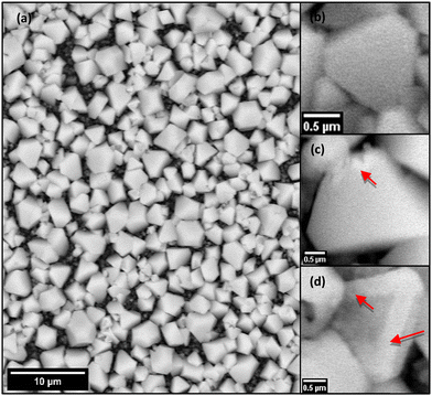 |
| | Fig. 1 (a) SEM of Zn-doped Cu2O and (b–d) CoNi-decorated Zn-doped Cu2O with different CoNi deposition times: (b) 30 s, (c) 60 s, (d) 150 s. | |
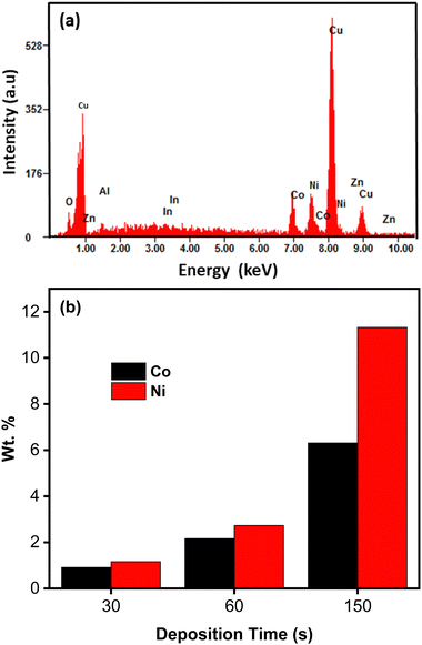 |
| | Fig. 2 (a) EDX spectrum of CoNi-decorated Zn-doped Cu2O with deposition time of 150 s. (b) Co and Ni fraction of the samples synthesized at different CoNi deposition times. | |
Fig. 3 shows the XRD pattern of CoNi-decorated Zn-doped Cu2O. The peaks correspond to the diffraction planes of (111), (200), (220), and (311) from Cu2O, located at 2θ = 36.14°, 42.31°, 61.38°, and 73.52°, respectively. Compared with the PDF card number 01-071-3645 for Cu2O, the peaks shifted to higher 2θ, which could be associated to the presence of Zn element in the Cu2O lattice.43–45 This result indicates that during the cathodic reaction, Zn ions entered and doped the Cu2O lattice. From the pattern, the existence of CoNi deposit was confirmed by the reflection from the (111) and (220) planes observed at 2θ = 44.36° and 76.12°, respectively.46
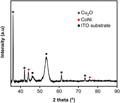 |
| | Fig. 3 XRD pattern of CoNi-decorated Zn-doped Cu2O with deposition time of 150 s. | |
Electrochemical impedance analysis
Fig. 4 shows Nyquist plots for an equivalent electrical circuit of the CoNi-decorated Zn-doped Cu2O. As indicated by the arc radius, the charge transfer resistance (Rct) measured under simulated solar irradiation was lower (1.11 kΩ) than that obtained without irradiation (3.80 kΩ, Fig. 4a). The low Rct value was due to the semiconductor characteristic of the Zn-doped Cu2O, which possessed good electron transfer kinetics under irradiation, since the adsorbed photon increased the carrier density,47 which could induce charge transfer reaction at the electrode–electrolyte interface.48 To confirm the role of CoNi cocatalyst, the electrochemical impedance characteristic of the bare Zn-doped Cu2O was measured. Fig. 4b shows the plot with a larger arc radius, indicating a higher charge transfer resistance (3.23 kΩ) compared to CoNi-decorated Zn-doped Cu2O. When the deposition time of CoNi increased up to 150 s, the arc radius of the CoNi-decorated Zn-doped Cu2O was found to decrease gradually (Fig. 4b), which means the resistance for charge transfer decreased by increasing the cocatalyst deposit.
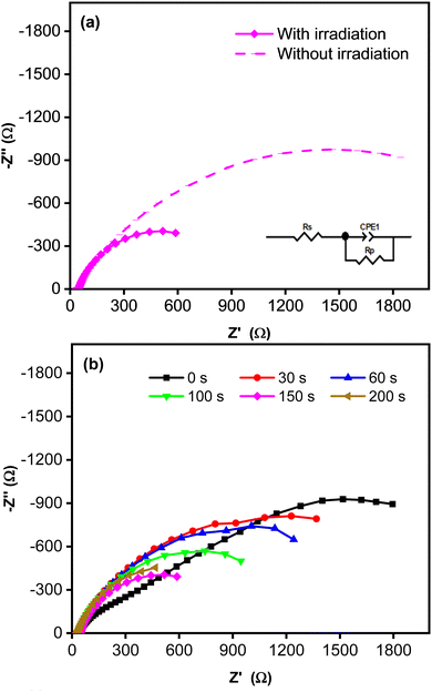 |
| | Fig. 4 (a) Nyquist plots measured without and with simulated solar irradiation for CoNi-decorated Zn-doped Cu2O synthesized with deposition time of 150 s. (b) Nyquist plots measured with simulated solar irradiation for Zn-doped Cu2O (0 s) and CoNi-decorated Zn-doped Cu2O with different deposition times of CoNi. | |
Photoelectrochemical analysis
Fig. 5 presents the photocurrent recorded using linear sweep voltammetry technique. Based on the LSV curves shown in Fig. 5a, photocurrent was initially recorded at a potential of 0.12 V vs. Ag/AgCl upon simulated solar irradiation, whereas a flat response was observed without irradiation. Under irradiation, photocurrent was generated by the formation of photoexcited electron (e−) and hole (h+) pairs driven by the adsorbed photon. To confirm the role of CoNi cocatalyst, the photocurrent of a bare Zn-doped Cu2O was measured and compared to the CoNi-decorated Cu2O. Fig. 5b demonstrates that CoNi cocatalyst increased photocurrent intensity of the Zn-doped Cu2O. On the photocatalyst surface, CoNi acts as an electron donor that increases the electric field and high-efficiency charge separation.49 Hence, the charge carriers increased and led to the increase of photocurrent. This conclusion was verified by the EIS measurements, which show the decrease of Rct values when Zn-doped Cu2O was decorated by the CoNi cocatalyst. Fig. 5b also shows that the longer the deposition time, the more photocurrent intensity increased. This result exhibits that an increase of CoNi cocatalyst increased the trapping of photoexcited electrons, which enhanced the charge carrier lifetime and induced the energy band bending of the photocathode, delaying the photoelectron and hole recombination21,29 that occurs due to the narrow band gap energy of Cu2O. However, the trend was not continued at 200 s. This is because the deposited CoNi became thick and blocked exposure of the Zn-doped Cu2O to photons, preventing the production of the photoexcited electron and hole.
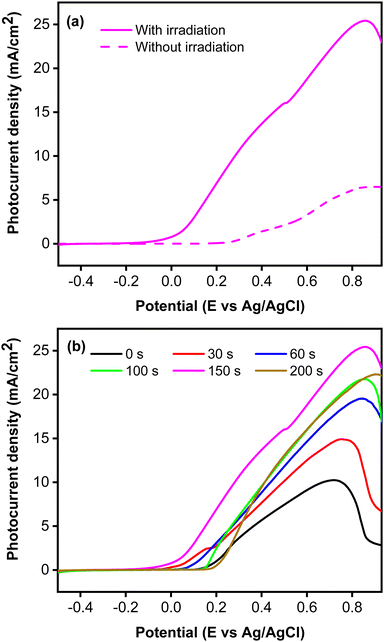 |
| | Fig. 5 (a) Photocurrent responses without and with irradiation measured from CoNi-decorated Zn-doped Cu2O synthesized with deposition time of 150 s. (b) Photocurrent responses with irradiation from Zn-doped Cu2O (0 s) and CoNi-decorated Zn-doped Cu2O with different CoNi deposition times. | |
To clarify the effect of CoNi deposition time on photostability, the photocurrent responses were recorded for two hours at 0.5 V vs. Ag/AgCl. Fig. 6 shows that the photostability of the samples increased with increasing deposition time from 0 to 150 s. Interestingly, the initial photocurrent density was reciprocal to the deposition time, most likely because the cocatalyst can act as a recombination center in the crystalline lattice.50 The photocurrent characteristics exhibit a strong correlation of photostability with CoNi deposition time. The steadiest photocurrent was obtained at 200 s, though its intensity was lower than that at 150 s. This could be attributed to the spreading of CoNi, which formed a protective layer and prevented photocorrosion by effectively trapping electrons and holes.51
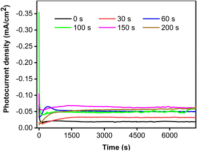 |
| | Fig. 6 Photocurrent stability of Zn-doped Cu2O (0 s) and CoNi-decorated Zn-doped Cu2O with different deposition times. | |
Analysis of photocatalytic methylene blue degradation
MB photodegradation was performed under simulated solar irradiation to evaluate the photocatalytic activity of the CoNi-decorated Zn-doped Cu2O. Based on the UV-Vis spectra (Fig. 7), the intensity of absorbance peaks decreases, which indicates the degradation of MB dye. Under irradiation, the photocatalyst absorbed photon energy and produced a photoexcited electron (e−) in the conduction band and hole (h+) in the valence band through the following mechanism:52| | | Cu2O + hv(UV) → Cu2O (e−(CB) + h+(VB)) | (2) |
The photoexcited electron was transferred to the dispersed CoNi on the surface. The accumulated electrons were then taken up by oxygen to form anionic superoxide radical (˙O2−), which could be protonated to form hydroperoxyl radical (˙OOH) and subsequently peroxide (H2O2). The H2O2 dissociated and formed hydroxyl radicals (˙OH).| | | O2 + e−(CB) → O2−(ads) | (3) |
| | | O2−(ads) + H+ → HOO˙(ads) | (4) |
| | | 2HOO˙(ads) → H2O2(ads) + O2 | (5) |
Meanwhile, in the valence band, the photogenerated hole reacted with water or hydroxyl ion (OH−) to generate hydroxyl radical (˙OH).| | | H2O(ads) + h+(VB) → OH˙(ads) + H+(ads) | (7) |
Hereinafter, the generated ˙OH species oxidized and degraded the MB compound through the following reaction mechanism.| | | Dye + OH˙ → CO2 + H2O (dye intermediates) | (8) |
| | | Dye + h+(VB) → oxidation products | (9) |
| | | Dye + e−(CB) → reduction products | (10) |
The schematic of the reaction mechanism of MB photodegradation by the CoNi-decorated Zn-doped Cu2O is illustrated in Fig. 8.
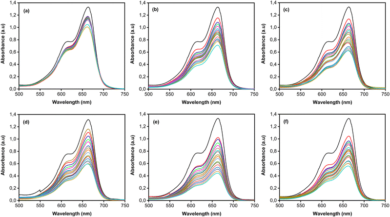 |
| | Fig. 7 UV-Vis absorbance spectra of (a) Zn-doped Cu2O (0 s) and CoNi-decorated Zn-doped Cu2O at different deposition times (b) 30 s; (c) 60 s; (d) 100 s; (e) 150 s; (f) 200 s. | |
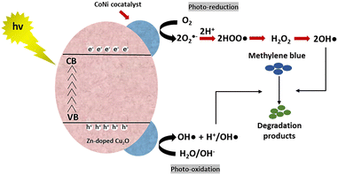 |
| | Fig. 8 Schematic of the reaction mechanism of MB photodegradation by CoNi-decorated Zn-doped Cu2O. | |
The degradation efficiency (η) of MB increased remarkably when the Zn-doped Cu2O was decorated with CoNi (Fig. 9). Further increase of degradation efficiency was obtained at longer deposition times.
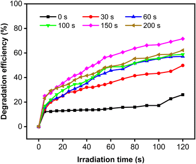 |
| | Fig. 9 Photodegradation of MB using Zn-doped Cu2O (0 s) and CoNi-decorated Zn-doped Cu2O with different CoNi deposition times. | |
The rate constant increase at longer deposition times of CoNi and the highest value was obtained at 150 s. The degradation efficiency (η) of MB increased remarkably when the Zn-doped Cu2O was decorated with CoNi (Fig. 9). Further increase of degradation efficiency was obtained at longer deposition times. Fig. 9 shows that the photodegradation reaction follows pseudo-first-order kinetics. From Fig. 10b, it is seen that the reaction kinetics exhibit linear correlation between ln(C0/C) and irradiation time. The rate constant increases with longer CoNi deposition time, and the highest value was obtained at 150 s.
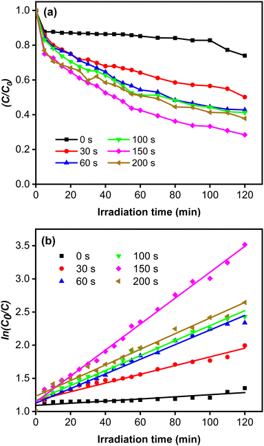 |
| | Fig. 10 (a) Photocatalytic reaction curves. (b) The corresponding first-order plots for MB degradation. | |
This photocatalytic enhancement could be attributed to the role of CoNi in increasing charge separation by acting as receptor for the photoexcited electron and preventing electron–hole pair recombination, which then increases the number of electrons initiating the catalytic reaction on the surface, as shown in Fig. 10.
This result is in accordance with a low charge transfer resistance in the EIS measurement, which indicates a rapid reaction involving the photogenerated charge has taken place. This explanation is confirmed by the high photocurrent of the CoNi-decorated Zn-doped Cu2O. However, due to the shadow effect, the photoelectrochemical properties deteriorated at 200 s and produced a relatively poor catalytic activity. Furthermore, CoNi also increased the photostability of the Zn-doped Cu2O under simulated solar irradiation. Fig. 11a shows the degradation percentage calculated using the following eqn (11).
| | | % photostability = (ηt/η0) × 100% | (11) |
Repeated measurements up to 15 cycles indicate that the photocatalyst is reusable, with relatively high photostability demonstrated by the CoNi-decorated Zn-doped Cu
2O (
Fig. 10a). Based on
Fig. 11b, the increase of deposition time led to a significant increase in photostability performance, from 18.11% to 42.19%. This indicates that CoNi decoration also protects Cu
2O, which is unstable under light irradiation in water medium.
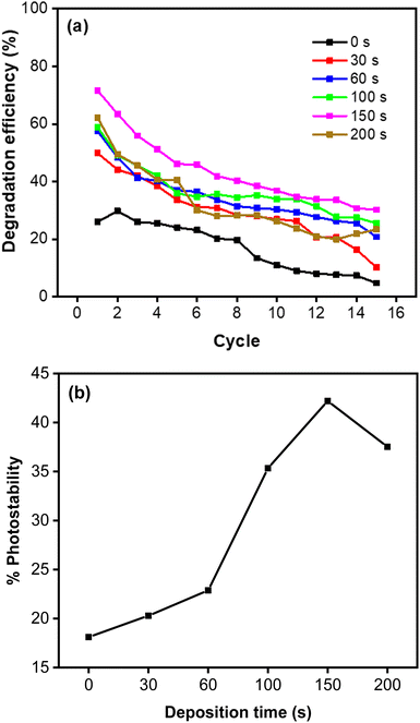 |
| | Fig. 11 (a) Photodegradation of MB measured for 15 cycles. (b) Photostability percentage of MB degradation. | |
Conclusions
CoNi-decorated Zn-doped Cu2O photocatalysts were successfully synthesized by electrodeposition technique. The CoNi-decorated Zn-doped photocatalyst demonstrated superior photoelectrochemical properties and photostability compared to the bare Zn-doped Cu2O. In this case, the electrodeposited CoNi decreased charge transfer resistance and increased the photocurrent under simulated solar irradiation. Longer deposition time produced more dispersed cocatalysts on the Cu2O crystals and resulted in a superior photocatalytic activity and photostability of the photocatalyst. The role of CoNi cocatalyst could be associated to its capability as receptor for the photoexcited electron, which increases charge separation and prevents electron–hole pair recombination, which then increases the number of electrons to initiate the reduction and oxidation reactions involving the adsorbed species on the surface. Furthermore, the increased photostability is attributed to the role of CoNi as a protective layer that inhibits Cu2O photocorrosion.
Conflicts of interest
There are no conflicts to declare.
Acknowledgements
This study was supported by Universitas Negeri Jakarta and Direktorat Riset, Teknologi dan Pengabdian kepada Masyarakat Kemendikbudristek of the Republic of Indonesia under Penelitian Terapan Kompetitif Nasional (PTKN) research scheme with contract number 6/PG.02.00.PT/LPPM/V/2022. The authors also thank The Center for Science Innovation (PT. Pusat Inovasi Sains) for providing the EDAQ ER466 potentiostat and Corrtest C310 workstation.
References
- C. Retamoso, N. Escalona, M. González, L. Barrientos, P. Allende-González, S. Stancovich, R. Serpell, J. L. G. Fierro and M. Lopez, J. Photochem. Photobiol., A, 2019, 378, 136–141 CrossRef CAS.
- A. G. Tamirat, J. Rick, A. A. Dubale, W. N. Su and B. J. Hwang, Nanoscale Horiz., 2016, 1, 243–267 RSC.
- H. Li, C. Chen, X. Huang, Y. Leng, M. Hou, X. Xiao, J. Bao, J. You, W. Zhang, Y. Wang, J. Song, Y. Wang, Q. Liu and G. A. Hope, J. Power Sources, 2014, 247, 915–919 CrossRef CAS.
- Z. Hao, Z. Liu, Y. Li, M. Ruan and Z. Guo, Int. J. Hydrogen Energy, 2020, 45, 16550–16559 CrossRef CAS.
- K. Pandiselvi, H. Fang, X. Huang, J. Wang, X. Xu and T. Li, J. Hazard. Mater., 2016, 314, 67–77 CrossRef CAS PubMed.
- K. Zhong, Y. Mao, X. Sun, C. Liang, P. Liu and Y. Tong, J. Electrochem. Soc., 2012, 159, K161 CrossRef CAS.
- M. Wang, Y. Liu, D. Li, J. Tang and W. Huang, Chin. Chem. Lett., 2019, 30, 985–988 CrossRef CAS.
- Z. Xu, C. Zhuang, Z. Zou, J. Wang, X. Xu and T. Peng, Nano Res., 2017, 10, 2193–2209 CrossRef CAS.
- R. S. Dariani, A. Esmaeili, A. Mortezaali and S. Dehghanpour, Optik, 2016, 127, 7143–7154 CrossRef CAS.
- S. Budi, W. A. Adi, Y. Yusmaniar, Z. Fairuza, I. Basori and A. A. Umar, Int. J. Electrochem. Sci., 2022, 17, 1–12 Search PubMed.
- I. Akhirudin, S. Budi and Y. Yusmaniar, J. Phys.: Conf. Ser., 2020, 1428, 012064 CrossRef.
- L. Zhang, D. Jing, L. Guo and X. Yao, ACS Sustainable Chem. Eng., 2014, 2, 1446–1452 CrossRef CAS.
- S. Budi, D. Indrawati, M. Arum and Y. Yusmaniar, AIP Conf. Proc., 2021, 2342, 060006 CrossRef CAS.
- X. Yu, J. Zhang, J. Zhang, J. Niu, J. Zhao, Y. Wei and B. Yao, Chem. Eng. J., 2019, 374, 316–327 CrossRef CAS.
- F. Hu, Y. Zou, L. Wang, Y. Wen and Y. Xiong, Int. J. Hydrogen Energy, 2016, 41, 15172–15180 CrossRef CAS.
- I. V. Bagal, N. R. Chodankar, M. A. Hassan, A. Waseem, M. A. Johar, D. H. Kim and S. W. Ryu, Int. J. Hydrogen Energy, 2019, 44, 21351–21378 CrossRef CAS.
- A. El-Shaer, M. T. Y. Tadros and M. A. Khalifa, Nat. Sci., 2015, 13, 14–22 Search PubMed.
- I. S. Brandt, M. A. Tumelero, E. Lima, D. L. da Silva, R. D. Zysler, R. Faccio and A. A. Pasa, J. Magn. Magn. Mater., 2017, 441, 374–386 CrossRef CAS.
- L. A. Stern, L. Liardet, M. T. Mayer, C. G. Morales-Guio, M. Grätzel and X. Hu, Electrochim. Acta, 2017, 235, 311–316 CrossRef CAS.
- X. Li, J. Wan, Y. Ma, Y. Wang and X. Li, Chem. Eng. J., 2021, 404, 127054 CrossRef CAS.
- Y. Yamada, K. Yano and S. Fukuzumi, Energy Environ. Sci., 2012, 5, 5356–5363 RSC.
- D. Chen, Z. Liu, Z. Guo, W. Yan and M. Ruan, Chem. Eng. J., 2020, 381, 122655 CrossRef CAS.
- F. Nur, I. Sari, C. Lin and J. Ting, Chem. Eng. J., 2019, 368, 784–794 CrossRef.
- X. Pang, H. Bai, Y. Zhao, L. Qu, D. Xu, J. Ding, W. Fan and W. Shi, Electrochim. Acta, 2020, 137453 Search PubMed.
- H. Qi, J. Wolfe, D. Fichou and Z. Chen, Nat. Publ. Gr., 2016, 4–11 CAS.
- H. Kim, J. Park, I. Park, K. Jin, S. E. Jerng, S. H. Kim, K. T. Nam and K. Kang, Nat. Commun., 2015, 6, 1–11 Search PubMed.
- P. Nazari, O. Nouri and S. Rahman Setayesh, J. Chem. Sci., 2020, 132(13), 13 CrossRef CAS.
- S. A. Lee, T. H. Lee, C. Kim, M. G. Lee, M. J. Choi, H. Park, S. Choi, J. Oh and H. W. Jang, ACS Catal., 2018, 8, 7261–7269 CrossRef CAS.
- M. Okazaki, Y. Suganami, N. Hirayama, H. Nakata, T. Oshikiri, T. Yokoi, H. Misawa and K. Maeda, ACS Appl. Energy Mater., 2020, 3, 5142–5146 CrossRef CAS.
- A. El Attar, L. Oularbi, S. Chemchoub and M. El Rhazi, J. Electroanal. Chem., 2021, 885, 115042 CrossRef CAS.
- A. El Attar, L. Oularbi, S. Chemchoub and M. El Rhazi, Int. J. Hydrogen Energy, 2020, 45, 8887–8898 CrossRef CAS.
- M. Abdelfatah, J. Ledig, A. El-Shaer, A. Sharafeev, P. Lemmens, M. M. Mosaad, A. Waag and A. Bakin, ECS J. Solid State Sci. Technol., 2016, 5, Q183–Q187 CrossRef CAS.
- A. Ico, N. Turmiasaputri, E. Handoko and S. Budi, Chem. Mater., 2022, 1, 61–65 CrossRef.
- M. Anand Raj and S. Arumainathan, Vacuum, 2019, 160, 461–466 CrossRef CAS.
- K. M. Hyie, A. Ahmad, N. A. Resali, M. F. Munir, C. S. Li and S. Saidin, Procedia Technol., 2014, 15, 792–797 CrossRef.
- N. Eliaz, K. Venkatakrishna and A. C. Hegde, Surf. Coat. Technol., 2010, 205, 1969–1978 CrossRef CAS.
- S. S. Patil, M. A. Johar, M. A. Hassan, D. R. Patil and S. W. Ryu, Sol. Energy, 2019, 178, 125–132 CrossRef CAS.
- M. Bučko, J. Rogan, B. Jokić, M. Mitrić, U. Lačnjevac and J. B. Bajat, J. Solid State Electrochem., 2013, 17, 1409–1419 CrossRef.
- I. J. Park, G. Kang, M. A. Park, J. S. Kim, S. W. Seo, D. H. Kim, K. Zhu, T. Park and J. Y. Kim, ChemSusChem, 2017, 10, 2660–2667 CrossRef CAS PubMed.
- M. G. Lee, D. H. Kim, W. Sohn, C. W. Moon, H. Park, S. Lee and H. W. Jang, Nano Energy, 2016, 28, 250–260 CrossRef CAS.
-
S. Kumar, S. Pande and P. Verma, Int. J. Curr. Eng. Technol.
- M. Mulyadi and A. Afrizal, Chem. Mater., 2022, 1, 40–44 CrossRef.
- K. Lee, C. H. Lee, J. Y. Cheong, S. Lee, I. D. Kim, H. I. Joh and D. C. Lee, Korean J. Chem. Eng., 2017, 34, 3214–3219 CrossRef CAS.
- N. G. Elfadill, M. R. Hashim, K. M. Chahrour and S. A. Mohammed, Semicond. Sci. Technol., 2016, 31, 0 CrossRef CAS.
- F. Ye, X. Q. Su, X. M. Cai, Z. H. Zheng, G. X. Liang, D. P. Zhang, J. T. Luo and P. Fan, Thin Solid Films, 2016, 603, 395–399 CrossRef CAS.
- S. Budi, B. Kurniawan, D. M. Mott, S. Maenosono, A. A. Umar and A. Manaf, Thin Solid Films, 2017, 642, 51–57 CrossRef CAS.
- Y. Yang, D. Xu, Q. Wu and P. Diao, Sci. Rep., 2016, 6, 1–13 CrossRef CAS PubMed.
- D. Yang, Y. Xu, K. Pan, C. Yu, J. Wu, M. Li, F. Yang, Y. Qu and W. Zhou, Chin. Chem. Lett., 2022, 33, 378–384 CrossRef CAS.
- G. Iervolino, I. Tantis, L. Sygellou and V. Vaiano, Appl. Surf. Sci., 2017, 400, 176–183 CrossRef CAS.
- A. K. R. Police, S. V. P. Vattikuti, K. K. Mandari, M. Chennaiahgari, P. S. Phanikrishna, D. K. Valluri and C. Byon, Ceram. Int., 2018, 44, 11783–11791 CrossRef CAS.
- A. Of, J. Yang, L. Berkeley, C. Physics and C. L. Guiyang, Acc. Chem. Res., 2013, 46, 1900–1909 CrossRef PubMed.
- A. Ajmal, I. Majeed, R. N. Malik, H. Idriss and M. A. Nadeem, RSC Adv., 2014, 4, 37003–37026 RSC.
|
| This journal is © The Royal Society of Chemistry 2023 |
Click here to see how this site uses Cookies. View our privacy policy here.  Open Access Article
 *a,
Mega Gladiani
Sutrisno
ab,
Yussi
Pratiwi
a and
Yusmaniar
a


