
 Open Access Article
 This Open Access Article is licensed under a
 Creative Commons Attribution 3.0 Unported Licence
Full-electric microfluidic platform to capture, analyze and selectively release single cells†
Ruben
Van den Eeckhoudt
 *a,
An-Sofie
Christiaens
b,
Frederik
Ceyssens
ah,
Vasileios
Vangalis
cd,
Kevin J.
Verstrepen
cd,
Nico
Boon
e,
Filip
Tavernier
f,
Michael
Kraft
ah and
Irene
Taurino
ag
*a,
An-Sofie
Christiaens
b,
Frederik
Ceyssens
ah,
Vasileios
Vangalis
cd,
Kevin J.
Verstrepen
cd,
Nico
Boon
e,
Filip
Tavernier
f,
Michael
Kraft
ah and
Irene
Taurino
ag
aMicro- and Nanosystems (MNS), Department of Electrical Engineering (ESAT), KU Leuven, Leuven, Belgium. E-mail: ruben.vandeneeckhoudt@kuleuven.be
bChemical and Biochemical Reactor Engineering and Safety (CREaS), Department of Chemical Engineering, KU Leuven, Leuven, Belgium
cVIB – KU Leuven Center for Microbiology, Leuven, Belgium
dCMPG Laboratory for Genetics and Genomics, KU Leuven, Leuven, Belgium
eCenter for Microbial Ecology and Technology (CMET), Faculty of Bioscience Engineering, Ghent University, Ghent, Belgium
fMICAS, Department of Electrical Engineering (ESAT), KU Leuven, Leuven, Belgium
gSemiconductor Physics, Department of Physics and Astronomy, KU Leuven, Leuven, Belgium
hLeuven Institute for Micro- and Nanoscale Integration (LIMNI), KU Leuven, Leuven, Belgium
First published on 29th August 2023
Abstract
Current single-cell technologies require large and expensive equipment, limiting their use to specialized labs. In this paper, we present for the first time a microfluidic device which demonstrates a combined method for full-electric cell capturing, analyzing, and selectively releasing with single-cell resolution. All functionalities are experimentally demonstrated on Saccharomyces cerevisiae. Our microfluidic platform consists of traps centered around a pair of individually accessible coplanar electrodes, positioned under a microfluidic channel. Using this device, we validate our novel Two-Voltage method for trapping single cells by positive dielectrophoresis (pDEP). Cells are attracted to the trap when a high voltage (VH) is applied. A low voltage (VL) holds the already trapped cell in place without attracting additional cells, allowing full control over the number of trapped cells. After trapping, the cells are analyzed by broadband electrochemical impedance spectroscopy. These measurements allow the detection of single cells and the extraction of cell parameters. Additionally, these measurements show a strong correlation between average phase change and cell size, enabling the use of our system for size measurements in biological applications. Finally, our device allows selectively releasing trapped cells by turning off the pDEP signal in their trap. The experimental results show the techniques potential as a full-electric single-cell analysis tool with potential for miniaturization and automation which opens new avenues towards small-scale, high throughput single-cell analysis and sorting lab-on-CMOS devices.
Introduction
Single-cell analysis techniques are essential tools for biomedical and microbial research. These techniques can detect subtle differences between individual cells in a population (“phenotypic heterogeneity”). In contrast, the commonly used bulk analysis technologies measure the average response of the entire population, which may mask the response of a subpopulation.1 Several single-cell analysis techniques exist, such as flow cytometry and micro-Raman spectroscopy. However, these techniques are expensive, require sizeable equipment and they require sample preparation for cell labeling (flow cytometry)2 or they operate slowly, which makes the sampling of an entire population time-consuming (Raman spectroscopy).3Electrical analysis devices have the potential to become a non-invasive and label-free addition to the already existing single-cell techniques.4 However, a sufficiently high throughput is required to effectively sample populations in a reasonable time. Two categories of electrical devices for single-cell analysis currently being researched show a high potential: impedance flow cytometry (IFC) and complementary metal-oxide-semiconductor micro electrode arrays (CMOS MEAs).5 Both techniques have a high throughput and are label-free. In IFC systems, the electrical impedance of cells is measured as they flow through a microfluidic channel.6 However, due to the high velocity of the cells, there is only a short detection time which limits the number of frequency points and the sensitivity of the measurement. In CMOS MEA systems, cells adhere to an array of microelectrodes from which they can be analyzed in parallel. The microelectrodes are post-processed on a CMOS chip containing signal-processing electronics. This integrated approach enables the analysis of many sensing channels in parallel. These systems can be utilized for detailed real-time analysis and have been implemented with a variety of sensing techniques, including impedance spectroscopy, action potential recording, electrochemical measurements and electroporation.7–9 However, since the cells need to be in the proximity of the electrodes for a sensitive measurement, the application of CMOS MEA systems is currently limited to cells adhering to the MEA surface. These applications include cells that naturally adhere, slices of tissue, or biofilms cultivated on the MEA surface.10,11 Many cells, however, naturally occur in suspension, such as several yeasts and bacteria strains or red blood cells. To allow CMOS MEA systems to be used for these applications, there is a need for efficient and full-electric single-cell trapping techniques that can be incorporated into a chip. Additionally, individual control of the traps is necessary to capture and release cells selectively to facilitate sorting with single-cell resolution.
Various single-cell trapping techniques have been described in the literature.12 Surface functionalization of the electrodes with, e.g., antibodies can be a powerful tool to immobilize cells, but the binding is permanent; hence there is no possibility for releasing and sorting the cells. Cell sedimentation in microwells13 and hydrodynamic trapping14 are effective methods to trap large numbers of cells, but the traps are not individually controlled, which precludes a selective release. Optical tweezers can precisely manipulate single cells, but they are complex and require large, specialized equipment.15
Dielectrophoresis (DEP), in contrast, is an excellent candidate for single-cell trapping on a CMOS chip.16,17 A particle or cell is subjected to a DEP force when in a spatially non-uniform electric field.18 A set of microelectrodes is necessary to generate this electric field for cell trapping. Post-processing microelectrodes on a CMOS chip has been widely reported in the literature.19 Furthermore, the dielectrophoretic force can be controlled by manipulating the applied electric signal using on-chip electronics, hence individual control of single-cell traps is possible to facilitate cell sorting.
Electrochemical impedance spectroscopy (EIS) is a label-free electric technique widely used for extracting cell parameters such as membrane capacitance and cytoplasm conductivity. The acquired parameters can be related to biological properties such as cell viability, size, growth state, etc.20 Several devices reported in the literature have combined EIS with trapping techniques to characterize cells in suspension. This combination is interesting for applications where a real-time analysis of a single cell is required. Some of these devices have utilized hydrodynamic traps for various applications e.g., to judge the quality of oocytes meant for in vitro fertilization,21 to record the response of single cells to a toxin22 or to analyze the differentiation process of mouse embryonic stem cells.23
Microfluidic devices combining DEP and EIS for capturing and analyzing cells can provide full-electric control over single-cell capturing, analyzing and releasing. Devices using negative DEP (nDEP) traps24 and a single positive DEP (pDEP) trap25 were reported for capturing single cells in combination with EIS measurements. However, these devices were used for large (>10 μm) mammalian cells and did not report selective releasing, which is necessary for cell sorting. Full-electric devices have been reported for use on cells as small as bacteria (around 1 μm). However, they were not single-cell methods since they captured large numbers of cells on the same electrode pair, and the impedance was measured only at a single frequency.25–27 A microfluidic device that could selectively release trapped yeast cells by negative DEP after EIS analysis was recently reported. However, they used a pressure difference to hydrodynamically trap multiple cells simultaneously and they measured a different type of yeast.28,29
Here we present for the first time a microfluidic device which demonstrates a method for full-electric cell capturing, analyzing, and selectively releasing with single-cell resolution. We propose and validate a novel full-electric method for single-cell capturing based on pDEP, which we call the Two-Voltage method. After capturing, single yeast cells down to 3 μm diameter are analyzed by broadband EIS measurements. Cells can be selectively released from the trap by turning off the pDEP signal in the trap. Our full-electric technique has the potential for miniaturization and automation, which will open up avenues to a high-throughput integrated single-cell analysis system.
Materials and methods
Device fabrication
The fabrication of the microfluidic chip is shown in Fig. 1A and can be summarized as follows: (i) gold electrodes (200 nm Au with Ti adhesion layer, both deposited by sputtering) were patterned on a glass wafer using a lift-off process that uses LOR10B and S1818 photoresist as sacrificial layers. A first layer of SU8 (5 μm thickness) was spin-coated and patterned to define the traps (ii). Each trap was located over two coplanar electrodes. This layer also functioned as a passivation layer for the electrode connections. A second layer of SU8 was spin-coated and patterned to define the microfluidic channel (iii). A bare PDMS slab was bonded to the second SU8 layer to seal the channel (iv). To achieve this bond, the PDMS slab was coated with a layer of APTES (3-aminopropyl triethoxysilane) by activating the surface in oxygen plasma and dipping the activated surface in a 1% (aq) APTES solution, followed by a thorough rinse in methanol and DI water.30 The coated surface of the PDMS slab was then put in contact with the SU8 layer on the chip and baked at 150 °C for 1 hour which resulted in a tight bond. Afterwards, the gold electrodes were post-processed by applying a constant potential of 16 V over the electrodes for 1 s while the electrodes were immersed in 100× diluted PBS solution to achieve a rough and nanostructured surface. | ||
| Fig. 1 (A) Fabrication steps of the microfluidic platform. i) Deposition of gold micro-electrodes on a glass substrate wafer. ii) Patterning the first SU-8 layer. iii) Patterning the second SU-8 layer. iv) Bonding of unstructured PDMS slab to top SU-8 layer. (B–E) Schematic drawing of the side view of the microfluidic channel illustrating the operation of the device for single-cell trapping, analyzing and selective releasing. (B) Cells in the channel are attracted to the traps by pDEP forces due to the VH signal applied over the electrode pairs. (C) Once a cell is trapped, the voltage over the electrode pair is switched to VL. The cell remains trapped, but no additional cells from the channel are attracted. (D) The flow in the channel is reduced to zero and the coplanar electrodes are one by one connected to an impedance analyzer for impedance measurements. (E) VL is reapplied over the electrodes to keep the cells in place while the flow rate is increased. Single cells are selectively released by turning off the voltage over the electrode pair. | ||
Device dimensions
The microfluidic channel had a width of 300 μm and a height of 15 μm. Eight traps with a depth of 5 μm were positioned under the channel. The traps were designed in four sizes, with two traps of each size present on the device. The sizes were 30 μm × 60 μm, 60 μm × 60 μm, 90 μm × 60 μm and 120 μm × 60 μm. Each trap was centered over a coplanar electrode pair with a gap of 4 μm. The width of the electrodes varied from 30 μm to 120 μm according to the trap size. The length of each electrode was 28 μm. For consistency, the EIS measurements reported in this paper were all measured using the 60 μm × 60 μm electrodes.PCB and experimental setup
The experimental setup is schematically shown in Fig. S1.† The chip was placed in a custom 3D-printed holder. The PCB was placed over the holder and tightened with screws. The connection between the PCB and the chip pads was made with spring connectors. The PCB contained eight switches, each for selecting one of the traps. Two additional switches on the PCB allowed changing between DEP and EIS functionality. Each electrode pair's bottom electrodes were connected to a common electrode. This electrode could be switched to the stimulation voltage of the impedance analyzer or ground. The top electrode of each electrode pair was individually accessible. It could be switched to five different terminals: the sensing terminal of the impedance analyzer, the guard of the impedance analyzer, the high voltage signal, the low voltage signal, and the ground.The chip and PCB were placed under a large working distance microscope used to monitor the cells in the microfluidic channel. A syringe pump with a 100 μl Hamilton glass syringe containing the cells in solution was connected to the chip via microfluidic tubing. A Wayne Kerr precision impedance analyzer 6500B was connected to the PCB to perform the EIS measurements. Finally, two Rigol waveform generators were connected to the PCB to apply sinusoidal voltage signals to the electrodes: high voltage (VH) and low voltage (VL) at a frequency of 5 MHz. The used values for VH and VL were dependent on the flow rate in the channel. This point is further discussed in section 3.1.
Simulations
Simulations of the DEP force in the trapping area were performed using the electric currents interface in COMSOL Multiphysics. The 60 μm by 60 μm trap was modeled with an AC voltage amplitude of 1 V applied to one electrode while the other was grounded. From these simulations, the value and direction of the gradient of the squared electric field were derived.Cell preparation
Bakers' yeast (Saccharomyces cerevisiae, Bruggeman) was grown on 15 g L−1 agar (Fisher Scientific) YPD (yeast extract–peptone–dextrose) plates containing 10 g L−1 yeast extract (Fisher Scientific), 20 g L−1 peptone (Sigma-Aldrich) and 20 g L−1 dextrose (Fisher Scientific), or in YPD broth. Agar plates were inoculated from 20% w/v glycerol stock, grown overnight at 30 °C and stored at 4 °C until further use. Liquid cultures were inoculated from single colonies and incubated in shake flasks at 30 °C and 150 rpm. Cells were harvested during the exponential growth phase, when the yeast was budding, by centrifuging at 3220 × g for 10 minutes, washing twice in 1![[thin space (1/6-em)]](https://www.rsc.org/images/entities/char_2009.gif) :100 phosphate-buffered saline (PBS, Invitrogen, pH 7.4) diluted in Milli-Q water and finally resuspending in the 1:100 PBS solution. In the experiments, a concentration of 1–2 × 10⁶ cells per ml was used. All EIS measurements were performed on the same day the cells were harvested. Non-budding yeast cells were prepared in the same way as the budding yeast, except they were harvested during the stationary phase. The experiments in this paper were performed on budding yeast cells, unless otherwise stated.
:100 phosphate-buffered saline (PBS, Invitrogen, pH 7.4) diluted in Milli-Q water and finally resuspending in the 1:100 PBS solution. In the experiments, a concentration of 1–2 × 10⁶ cells per ml was used. All EIS measurements were performed on the same day the cells were harvested. Non-budding yeast cells were prepared in the same way as the budding yeast, except they were harvested during the stationary phase. The experiments in this paper were performed on budding yeast cells, unless otherwise stated.
Results and discussions
Single-cell trapping and releasing
Fig. 1(B–E) schematically illustrates the operational principle of our microfluidic device, which utilizes a fully electric approach to capture, analyze, and selectively release single cells. The device utilized our novel Two-Voltage method for single-cell trapping using positive dielectrophoresis. Individually accessible coplanar electrodes in each trap could be switched between two voltage signals: a high voltage (VH) and a low voltage (VL). Applying a sinusoidal voltage (VH) over the electrodes resulted in a pDEP force that attracted the cells from the channel and trapped them in the gap between the electrodes (Fig. 1B). Once a cell was trapped, the electrodes were switched to the lower applied voltage (VL) to reduce the pDEP force. The weaker force was strong enough to hold the trapped cell in place without capturing additional cells from the microfluidic channel (Fig. 1C). Using this method, single cells were captured on the coplanar electrode traps.Afterwards, the impedance of the trapped cells was measured using the same electrodes. The channel's flow rate was first reduced to zero and subsequently the pDEP force was deactivated. The cells remained immobilized since there was no flow. The impedance of the trapped cells was then measured one by one by connecting the electrodes to a benchtop impedance analyzer (Fig. 1D). After impedance measurements, the cells were selectively released. VL was applied again in the traps to hold the cells in place while the flow rate in the channel was increased. Cells were then selectively released from their trap by turning off the voltage signal in the trap of the cell that the operator wanted to release. This resulted in cells leaving the trap and being taken by the flow in the microfluidic channel (Fig. 1E). The method can allow our system to selectively release single cells based on the results from the impedance study.
The trapping principle relied on the pDEP force to capture and hold cells in place. This force is exerted on a cell when it is subjected to a spatially non-uniform electric field and can be described as follows for spherical particles:31
 | (1) |
 is the time-averaged DEP force vector, r is the particle's radius, εm the permittivity of the surrounding medium, Re{fCM} denotes the real part of the frequency-dependent Clausius–Mossotti factor fCM and
  the root mean square electric field vector. The Clausius–Mossotti factor is defined as
 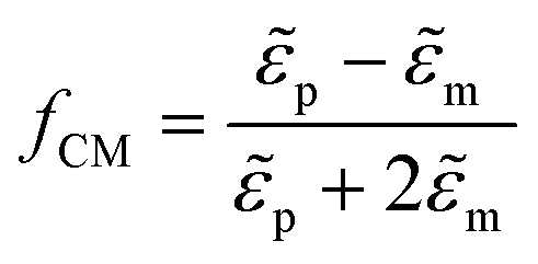 with
with ![[small epsilon, Greek, tilde]](https://www.rsc.org/images/entities/i_char_e0de.gif) p and m the complex permittivity of the particle and medium, respectively. fCM ranges between −0.5 and 1 and determines the sign of the DEP force. When positive, the particle is attracted toward regions of a high electric field (positive DEP). When negative, it is repelled from them towards low electric field regions (negative DEP). For the correct operation of the microfluidic device, a positive DEP force was required. The fCM factor for the DEP force on yeast cells is highly dependent on the frequency of the applied electrical signal and the conductivity of the medium. Using previously reported yeast cell properties,32 Re{fCM} was calculated for the cells and medium used in our experiments and is shown in Fig. 2A. Details of the calculation can be found in the ESI.† At frequencies below 1 MHz and above 100 MHz, Re{fCM} is negative, indicating a negative DEP force. Between 250 kHz and 200 MHz, Re{fCM} is positive, reaching a maximum value of 0.6 at 10 MHz. In experiments on yeast cells, we observed a strong pDEP force acting on the cells when applying a 5 MHz excitation signal, which is in line with the simulated results of fCM. In all experiments described in this paper, the DEP signal frequency was set at 5 MHz.
p and m the complex permittivity of the particle and medium, respectively. fCM ranges between −0.5 and 1 and determines the sign of the DEP force. When positive, the particle is attracted toward regions of a high electric field (positive DEP). When negative, it is repelled from them towards low electric field regions (negative DEP). For the correct operation of the microfluidic device, a positive DEP force was required. The fCM factor for the DEP force on yeast cells is highly dependent on the frequency of the applied electrical signal and the conductivity of the medium. Using previously reported yeast cell properties,32 Re{fCM} was calculated for the cells and medium used in our experiments and is shown in Fig. 2A. Details of the calculation can be found in the ESI.† At frequencies below 1 MHz and above 100 MHz, Re{fCM} is negative, indicating a negative DEP force. Between 250 kHz and 200 MHz, Re{fCM} is positive, reaching a maximum value of 0.6 at 10 MHz. In experiments on yeast cells, we observed a strong pDEP force acting on the cells when applying a 5 MHz excitation signal, which is in line with the simulated results of fCM. In all experiments described in this paper, the DEP signal frequency was set at 5 MHz.
 | ||
Fig. 2 (A) Calculated real part of the Clausius–Mossotti factor for Saccharomyces cerevisiae in 100× diluted PBS. (B) Simulation of  in a 60 μm × 60 μm trap underneath a microfluidic channel. Colors indicate the magnitude of the vector; arrows indicate the direction. (C) Microscope image of the traps with coplanar electrodes along the microfluidic channel. Single yeast cells, highlighted with a red circle, are trapped. The orange dotted lines indicate the edges of the microfluidic channel. in a 60 μm × 60 μm trap underneath a microfluidic channel. Colors indicate the magnitude of the vector; arrows indicate the direction. (C) Microscope image of the traps with coplanar electrodes along the microfluidic channel. Single yeast cells, highlighted with a red circle, are trapped. The orange dotted lines indicate the edges of the microfluidic channel. | ||
The coplanar electrodes in the trap area generated a spatially non-uniform electric field when a voltage was applied over them. Near the gap between the electrodes, the electric field strength was maximal and decreased with the distance from the gap. For this reason, cells were attracted towards this gap in the case of pDEP. Fig. 2B shows a simulation of the modulus of  , which is directly proportional to the DEP force as denoted in eqn (1), within the microfluidic channel surrounding a 60 μm × 60 μm trap.
  reduced exponentially with the distance from the gap between the electrodes. The value in the channel was approximately 100 times lower than in the electrode gap. The DEP force on a trapped cell was therefore much higher than on a cell flowing through the microfluidic channel. This property was essential to make the microfluidic system work. Applying the high voltage VH to the electrodes leads to a sufficiently high pDEP force in the channel to pull cells toward the electrode gap and capture them. Lowering the voltage to VL resulted in a decrease in the strength of the pDEP force, which was insufficient to draw new cells from the channel. However, the force remained strong enough in the gap to keep the trapped cell in position. Using this method, single cells were trapped simultaneously on the electrodes, as shown in Fig. 2C. The 30 μm × 60 μm and 60 μm × 60 μm electrode pairs provided the best results for single cell capturing. With the other geometries, it was more difficult to capture single cells since they were larger and sometimes captured two cells at the same time.
Characterization of the trapping and holding principle
The voltage dependency of cell capturing was experimentally verified. A 5 MHz voltage signal was applied to the 60 μm × 60 μm electrodes for 60 s while cells were injected into the microfluidic channel at a flow rate of 20 μl h−1. The average amount of cells captured during these experiments for different applied voltages is shown in Fig. 3A. Below 2 Vpp (peak-to-peak voltage of the sine wave), the pDEP force was not strong enough to capture cells flowing in the channel. From 3 Vpp, the number of captured cells increased and leveled off above 4 Vpp. There was no significant increase in trapped cells between 4 Vpp and 5 Vpp since all cells which passed over the electrode were trapped. VH should be sufficiently high to attract cells in the channel and capture them, a VH of 4 Vpp or higher is suitable under the conditions of this experiment. | ||
| Fig. 3 (A) Average number of cells trapped on the coplanar electrodes during 60 s for different applied potentials. Sample sizes were 14, 14, 16, 12 and 6 for the 1 Vpp to 5 Vpp measurements respectively. (B) Average percentage of cells released from the trap after switching from 5 Vpp to a lower applied potential. Sample sizes were 8, 8, 10 and 8 for 1 Vpp to 4 Vpp respectively. (C) i)–iii) Capturing single cells, indicated by the red circle, on the traps. iv)–vii) Selective releasing of the trapped cells. | ||
There are two requirements to set the value for the low voltage VL. Firstly, it should be low enough to refrain from capturing cells flowing in the channel. Secondly, it should be high enough to hold already trapped cells in place without releasing them. The results in Fig. 3A suggest that a voltage lower than 2 Vpp satisfies the first requirement. To quantify the second requirement, the voltage dependency for holding captured cells was experimentally investigated. Firstly, a VH of 5 Vpp was applied to the 60 μm × 60 μm electrodes for 60 s with a flow rate of 20 μl h−1. Between 1 and 7 cells were trapped on the electrodes. Secondly, the voltage was switched to VL. Fig. 3B plots the average percentage of cells released after switching the voltage for different VL. When switching to 1 Vpp, all trapped cells were released. For 3 Vpp and above, almost no cells were released (<5%). Hence, a voltage of 3 Vpp or higher satisfies the second requirement. Therefore, the optimal voltage for VL was between 2 Vpp and 3 Vpp. Experimentally we found that a VL of 2.5 Vpp lead to a satisfactory result in fulfilling the two conditions. Note that the optimal voltages for VH and VL were highly dependent on the flow rate used in the experiment. The voltage values shown in Fig. 3A and B were valid for a flow rate of 20 μl h−1. Higher flow rates lead to higher optimal voltages.
The microscope images in Fig. 3C illustrate the capturing and selectively releasing of single cells on four electrode pairs. In this experiment, the flow rate was set at 5 μl h−1 and the values used for VH and VL were 3 Vpp and 0.5 Vpp, respectively. A single cell was captured on the top left and bottom right electrodes and their applied voltage was set at VL; on the other two electrodes VH was applied (i). Subsequently, single cells were captured on the other two traps (ii)–(iii). Lastly, the selective release of single cells was demonstrated by switching off the voltage in the traps (iv)–(vii). Following the removal of the applied voltage, the cells were released from the trap and taken by the flow in the channel (ESI† Videos S1 and S2).
The device currently does not allow for the downstream collection of the selectively released cells since there is only a single microfluidic channel on the chip. In future work, the chip could include extra output channel(s) for the collection of the selectively released cells similar to other well-established cell retrieval methods described in the literature.33–35
The system requires the cells under test to be subjected to a positive DEP force at the applied frequency. Cells subjected to negative DEP or no DEP force will not be captured in the trap. However, many cell types exhibit a positive DEP response in some frequency bands. Saccharomyces cerevisiae shows a pDEP response from 250 kHz to 200 MHz in the medium we used in the experiments (Fig. 2A). Other cell types like red blood cells36 or E. coli bacteria27 have all been reported to exhibit positive DEP. The Two-Voltage method of our system could, therefore, also be used for applications involving many other cell types.
In the current implementation of our system, the throughput of cell capturing is limited due to two reasons. Firstly, single cells are trapped by manually switching the voltage in each trap from VH to VL using slide switches on the PCB. We will automate this procedure in the future to drastically improve the throughput of single-cell capturing. Our idea is to measure the current of the 5 MHz DEP signal (VH) at every trapping site. When a cell is captured, the impedance in the trap changes and therefore the measured current changes. This signal will act as a trigger to electrically switch the voltage in this trap from VH to VL. In future work, this functionality will be programmed in a microcontroller such that no more manual switching is needed to capture single cells.
Secondly, to increase the number of trap sites on the device, we will implement our Two-Voltage method into a lab-on-CMOS device. These devices can have more than 100000 pixels,7 which in our case would be trapping sites. Since our method is fully electric, all functionalities, also the automation described above, can be integrated on the CMOS chip.
Impedance measurements
The equivalent electric circuit for the impedance measurements of an empty and filled trap is shown in Fig. 4A and B respectively.37Cpar describes the parasitic capacitance due to the electrical connections, CPEDL is a constant phase element representing the electrical double layer at the liquid–metal interface and Rsol relates to the resistance of the medium. The CPE impedance is given by ZCPE = 1/Q(j2πf)α with α, Q fitting parameters, and f the frequency. The cell was modelled as a resistor Rcyto in series with a capacitor Cmem, where the resistor is related to the cytoplasm and the capacitor describes the insulating membrane.38 When multiple cells are present, the circuit of Fig. 4B was also used as a lumped representation of multiple R–C circuits in parallel. A higher Cmem and lower Rcyto are expected for increasing number of trapped cells.
 | ||
| Fig. 4 Equivalent electric circuit of the coplanar electrodes of the trap in solution (A) without and (B) with a trapped cell. Impedance measurement (C) without a cell on the electrode pair and the best fit to the equivalent circuit without a cell, (D) with a single cell on the electrode pair, and the best fit to the equivalent circuit with and without a cell. | ||
A typical impedance measurement of an electrode pair without and with a trapped cell are shown in Fig. 4C and D respectively. The measurement without cell was taken immediately after the trapped cell was released. The fit of both measurements to their corresponding equivalent circuit is shown in the same figures. The calculated average approximation error (Table 1) is small for both fits, indicating that the chosen equivalent circuits are a good approximation for the measurements. For comparison, the single cell measurement was also fitted to the circuit without cell (Fig. 4A). The result, shown as the blue curves in Fig. 4D, does not provide a good fit for frequencies above 100 kHz. This is also indicated by the higher average approximation error (Table 1). The deviation is caused by the impedance of the cell for which the equivalent circuit without cell cannot account, since Rcyto and Cmem are not included.
| Measurement | One cell | No cell | |
|---|---|---|---|
| Equivalent circuit | No cell | One cell | No cell |
| Average magnitude error [%] | 5.20 | 3.16 | 3.20 |
| Average phase error [%] | 2.88 | 2.02 | 2.11 |
Cell impedance measurements from 17 experiments were fitted to the equivalent circuit of Fig. 4B and the parameters Rcyto and Cmem were extracted from the fit. During the measurement, either one, three or six cells were present in the trap. Fig. 5A shows the extracted Rcyto and Cmem values for the number of cells in the trap. The data points are grouped in clusters according to the trapped cell number. Furthermore, we could detect single cells and separate them from the three and six cell measurements. The graph shows a clear trend in the data towards lower Rcyto and higher Cmem when more cells are present in the trap, which is in accordance with the lumped model since the cells on the electrode appear in parallel. The yeast cells used in the experiments were in the budding process, which affected their shape and size. A significant variation in cell size was observed by visual inspection through a microscope since some cells were in a later stage of budding than others. This size variation is likely the main cause for the spread of impedance data. Other factors such as cell position, cell orientation and electronic noise also contributed.
 | ||
| Fig. 5 (A) Scatter plot of the extracted values of Cmem and Rcyto from 17 measurements where either one, three, or six cells were trapped on the electrode pair. Average change in phase (B) and magnitude (C) before and after releasing trapped cells for the measurements with one, three and six trapped cells and measurements without trapped cells as a control. Sample sizes were 7, 4, 7 and 6 for the 0, 1, 3 and 6 cells measurements respectively. (D) Average impedance phase shift between 100 and 300 kHz with respect to the size of single yeast cells. | ||
A second method was used to analyze cell impedance data in addition to circuit fitting. The reference measurement, measured immediately after the cell was released, was subtracted from the impedance measurement with the cell(s) to assess the contribution of the cell in the impedance spectrum. In Fig. 5B and C, the average change in phase and magnitude, respectively, is shown over the frequency range of the measurements for one, three and six trapped cells. The standard errors are indicated in the graph. As a control, the average change in impedance for measurements when there were no trapped cells is also shown. The control measurements showed a stable impedance with an average impedance difference of zero over the frequency range. A slight deviation can be seen below 1 kHz, but this was not significant since the standard error is large. Furthermore, the electrical double layer dominated the impedance at these low frequencies. Hence there was no useful information about cell impedance at low frequencies.
When cells were present on the electrodes, the magnitude data showed a steep increase in the middle frequency range (1–100 kHz) for the three and six cell measurements. This increase can be related to the insulating cell membrane which blocked the current flowing through the solution, thereby increasing the electrical resistance. The single-cell measurements did not show a significant increase. Above 100 kHz, the magnitude reduced and eventually dropped below zero, reaching a minimum of −7% for single cells, −9% for three cells and −14% for six cells on average before it increased again. At these frequencies, the electric field penetrated through the cell membrane and current passed through the cell cytoplasm. Since the cell cytoplasm was more conductive than the surrounding medium, a negative magnitude difference is measured.
The phase angle also dropped above 100 kHz and reached a minimum of −2° for single cells, −4° for three cells and −7° for six cells on average. This phase drop is related to the polarization of the cell membrane,38 also called β-dispersion.39 Analysis of variance (ANOVA) tests per frequency indicated that the phase data of the four measurement groups (no cell, one cell, three cells and six cells) differed significantly (p < 0.05) in the frequency range of the phase drop (100 kHz to 1 MHz). Subsequent Tukey–Kramer tests were used as a post-hoc multiple comparison test to assess the significance of the pairwise differences between the four groups while accounting for varying sample sizes. The mean phases of all four groups differed significantly from each other around 180 kHz with p < 0.05. Hence, it can be concluded that our impedance sensor was able to measure single yeast cells. Furthermore, the sensor could measure one, three and six cells compared to a reference zero cell measurement and provided the accuracy to show that the one, three and six cells measurements differed significantly from each other around 180 kHz. In general, the measurements of one, three and six cells showed a similar impedance “fingerprint”, but the changes were relatively more significant when more cells were trapped.
In order to comprehend the impact of cell size on EIS measurements, an additional set of 16 single-cell measurements was conducted specifically on non-budding S. cerevisiae cells. It is worth noting that the previous experiments utilized budding yeast cells, which were in the replication phase and therefore exhibited an increased size. The presence of a cell on the electrodes caused a negative phase change which was more pronounced when multiple cells were trapped, as seen in Fig. 5B. For each single-cell measurement of the budding and non-budding yeast, this average phase drop was calculated between 100 and 300 kHz. The size (diameter) of each cell was measured from optical images. For budding cells, which do not resemble spheres but doublets, the largest dimension was measured because this dimension takes into account the size of the bud. The average phase change and size for each cell is shown in Fig. 5D. These data show a clear negative correlation between the phase change and cell size. This result indicates that part of the variation in the cell measurements was related to variations in cell size. Furthermore, cell size exhibits a correlation with factors such as the cell replication cycle, DNA content, and prevailing environmental conditions.40 Considering these associations, our system's capacity to measure cell size in yeast cultures presents a multitude of potential applications in the field of cell biology.41–44
Conclusions
This article presents for the first time a microfluidic device which demonstrates a method for full-electric cell capturing, analyzing, and selectively releasing with single-cell resolution. Using our device, we propose and validate a novel full-electric method for single-cell capturing based on pDEP, which we call the Two-Voltage method. This technique was experimentally demonstrated on Saccharomyces cerevisiae yeast cells. Trapped cells were analyzed by broadband impedance spectroscopy which allowed the detection of single cells and the extraction of cell parameters Rcyto and Cmem. Moreover, a strong correlation was observed between the phase change of individual yeast cells within the frequency range of 100 to 300 kHz and their respective sizes. This finding highlights the potential of our system in a multitude of biological applications that involve the measurement of cell size.41–44Since capturing, holding, analyzing and releasing of cells were entirely governed by electrical signals and switches, the device has the potential to be fully automated. This will drastically increase the throughput of single cell capturing compared to the current method, which requires slow manual switching. Future work will focus on automating the Two-Voltage method to improve the throughput of single-cell capturing. Our full-electric system will in the future be completely integrated into a lab-on-CMOS device, where many electrodes could be utilized in parallel, further increasing the throughput. Our device, therefore, opens new avenues towards small-scale, high throughput single-cell analysis and sorting devices.
Conflicts of interest
There are no conflicts to declare.Acknowledgements
This work is funded by the Flemish Fund for Scientific Research (FWO G020119N). We thank Yuting Guo and Barbara Ulčar (Ghent University) for their help with early experiments preceding this work. We would also like to thank prof. Ilse Smets (KU Leuven) for her help with revising the manuscript. Finally, we would like to thank Sybren De Boever (Vrije Universiteit Brussel and Ghent University) for his kind help with the statistical analysis of the impedance measurements.Notes and references
- R. Props, F. M. Kerckhof, P. Rubbens, J. De Vrieze, E. H. Sanabria, W. Waegeman, P. Monsieurs, F. Hammes and N. Boon, ISME J., 2017, 11, 584–587 CrossRef PubMed.
- C. Koch, S. Günther, A. F. Desta, T. Hübschmann and S. Müller, Nat. Protoc., 2013, 8, 190–202 CrossRef CAS PubMed.
- W. E. Huang, M. Li, R. M. Jarvis, R. Goodacre and S. A. Banwart, Shining light on the microbial world the application of Raman microspectroscopy, Elsevier Inc., 1st edn, 2010, vol. 70 Search PubMed.
- Y. Xu, X. Xie, Y. Duan, L. Wang, Z. Cheng and J. Cheng, Biosens. Bioelectron., 2016, 77, 824–836 CrossRef CAS PubMed.
- F. Mermans, V. Mattelin, R. Van den Eeckhoudt, C. Garcia-Timmermans, J. Van Landuyt, Y. Guo, I. Taurino, F. Tavernier, M. Kraft, H. Khan and N. Boon, Front. Microbiol., 2023, 14, 1233705 CrossRef.
- C. Honrado, P. Bisegna, N. S. Swami and F. Caselli, Lab Chip, 2021, 21, 22–54 RSC.
- C. M. Lopez, H. S. Chun, S. Wang, L. Berti, J. Putzeys, C. Van Den Bulcke, J. W. Weijers, A. Firrincieli, V. Reumers, D. Braeken and N. Van Helleputte, IEEE J. Solid-State Circuits, 2018, 53, 3076–3086 Search PubMed.
- J. Abbott, A. Mukherjee, W. Wu, T. Ye, H. S. Jung, K. M. Cheung, R. S. Gertner, M. Basan, D. Ham and H. Park, Lab Chip, 2022, 22, 1286–1296 RSC.
- M. Punjiya, A. Mocker, B. Napier, A. Zeeshan, M. Gutsche and S. Sonkusale, Biosens. Bioelectron., 2020, 150, 111931 CrossRef CAS PubMed.
- V. Viswam, R. Bounik, A. Shadmani, J. Dragas, C. Urwyler, J. A. Boos, M. E. J. Obien, J. Muller, Y. Chen and A. Hierlemann, IEEE Trans. Biomed. Circuits Syst., 2018, 12, 1356–1368 Search PubMed.
- S. Kumashi, D. Jung, J. Park, S. Tejedor-Sanz, S. Grijalva, A. Wang, S. Li, H. C. Cho, C. Ajo-Franklin and H. Wang, IEEE Trans. Biomed. Circuits Syst., 2021, 15, 221–234 Search PubMed.
- R. M. Johann, Anal. Bioanal. Chem., 2006, 385, 408–412 CrossRef CAS PubMed.
- S. Lindström and H. Andersson-Svahn, Biochim. Biophys. Acta, Gen. Subj., 2011, 1810, 308–316 CrossRef PubMed.
- Q. Luan, C. Macaraniag, J. Zhou and I. Papautsky, Biomicrofluidics, 2020, 14, 031502 CrossRef CAS PubMed.
- H. Zhang and K. K. Liu, J. R. Soc., Interface, 2008, 5, 671–690 CrossRef CAS PubMed.
- T. P. Hunt, D. Issadore and R. M. Westervelt, Lab Chip, 2007, 8, 81–87 RSC.
- H. Zhang, H. Chang and P. Neuzil, Micromachines, 2019, 10, 423 CrossRef PubMed.
- A. Ramos, H. Morgan, N. G. Green and A. Castellanos, J. Phys. D: Appl. Phys., 1998, 31, 2338–2353 CrossRef CAS.
- J. Müller, M. Ballini, P. Livi, Y. Chen, M. Radivojevic, A. Shadmani, V. Viswam, I. L. Jones, M. Fiscella, R. Diggelmann, A. Stettler, U. Frey, D. J. Bakkum and A. Hierlemann, Lab Chip, 2015, 15, 2767–2780 RSC.
- Z. Zhang, X. Huang, K. Liu, T. Lan, Z. Wang and Z. Zhu, Biosensors, 2021, 11, 470 CrossRef CAS PubMed.
- A. El Hasni, C. Schmitz, K. Bui-Göbbels, P. Bräunig, W. Jahnen-Dechent and U. Schnakenberg, Sens. Actuators, B, 2017, 248, 419–429 CrossRef CAS.
- D. Malleo, J. T. Nevill, L. P. Lee and H. Morgan, Microfluid. Nanofluid., 2010, 9, 191–198 CrossRef PubMed.
- Y. Zhou, S. Basu, E. Laue and A. A. Seshia, Biosens. Bioelectron., 2016, 81, 249–258 CrossRef CAS PubMed.
- X. Guo and R. Zhu, Sci. Rep., 2016, 6, 31392 CrossRef CAS PubMed.
- N. C. Chen, C. H. Chen, M. K. Chen, L. S. Jang and M. H. Wang, Sens. Actuators, B, 2014, 190, 570–577 CrossRef CAS.
- R. Hamada, H. Takayama, Y. Shonishi, L. Mao, M. Nakano and J. Suehiro, Sens. Actuators, B, 2013, 181, 439–445 CrossRef CAS.
- M. Kim, T. Jung, Y. Kim, C. Lee, K. Woo, J. Hun and S. Yang, Biosens. Bioelectron., 2015, 74, 1011–1015 CrossRef CAS PubMed.
- Y. Geng, Z. Zhu, Y. Wang, Y. Wang, S. Ouyang, K. Zheng, W. Ye, Y. Fan, Z. Wang and D. Pan, Electrophoresis, 2019, 40, 1436–1445 CrossRef CAS PubMed.
- Z. Zhu, O. Frey, N. Haandbaek, F. Franke, F. Rudolf and A. Hierlemann, Sci. Rep., 2015, 5, 1–14 Search PubMed.
- E. Metwalli, D. Haines, O. Becker, S. Conzone and C. G. Pantano, J. Colloid Interface Sci., 2006, 298, 825–831 CrossRef CAS PubMed.
- N. G. Green, in Electrokinetics and Electrohydrodynamics in Microsystems, ed. A. Ramos, Springer, Vienna, 2011, pp. 61–84 Search PubMed.
- S. Y. Tang, P. Yi, R. Soffe, S. Nahavandi, R. Shukla and K. Khoshmanesh, Anal. Bioanal. Chem., 2015, 407, 3437–3448 CrossRef CAS PubMed.
- K. S. Lee, F. C. Pereira, M. Palatinszky, L. Behrendt, U. Alcolombri, D. Berry, M. Wagner and R. Stocker, Nat. Protoc., 2021, 16, 634–676 CrossRef CAS PubMed.
- N. Shao, Y. Zhou, J. Yao, P. Zhang, Y. Song, K. Zhang, X. Han, B. Wang and X. Liu, Adv. Sci., 2023, 2204544, 1–13 Search PubMed.
- J. Breukers, K. Ven, C. Struyfs, L. Ampofo, I. Rutten, M. Imbrechts, F. Pollet, J. Van Lent, W. Kerstens, S. Noppen, D. Schols, P. De Munter, H. J. Thibaut, K. Vanhoorelbeke, D. Spasic, P. Declerck, B. P. A. Cammue, N. Geukens, K. Thevissen and J. Lammertyn, Small Methods, 2023, 2201477, 1–13 Search PubMed.
- H. J. Jeon, H. Lee, D. S. Yoon and B. M. Kim, Biomed. Eng. Lett., 2017, 7, 317–323 CrossRef PubMed.
- J. Hong, D. S. Yoon, S. K. Kim, T. S. Kim, S. Kim, E. Y. Pak and K. No, Lab Chip, 2005, 5, 270–279 RSC.
- H. Morgan, T. Sun, D. Holmes, S. Gawad and N. G. Green, J. Phys. D: Appl. Phys., 2007, 40, 61–70 CrossRef CAS.
- H. P. Schwan, Adv. Biol. Med. Phys., 1957, 5, 147–209 CAS.
- J. J. Turner, J. C. Ewald and J. M. Skotheim, Curr. Biol., 2012, 22, R350–R359 CrossRef CAS PubMed.
- P. Jorgensen, N. P. Edgington, B. L. Schneider, I. Rupes, M. Tyers and B. Futcher, Mol. Biol. Cell, 2007, 18, 3523–3532 CrossRef CAS PubMed.
- D. M. Garcia, E. A. Campbell, C. M. Jakobson, M. Tsuchiya, E. A. Shaw, A. L. Dinardo, M. Kaeberlein and D. F. Jarosz, eLife, 2021, 10, 1–41 Search PubMed.
- J. Borgqvist, N. Welkenhuysen and M. Cvijovic, Sci. Rep., 2020, 10, 1–14 CrossRef PubMed.
- N. Fukuda, Sci. Rep., 2023, 13, 1–7 CrossRef PubMed.
Footnote |
| † Electronic supplementary information (ESI) available. See DOI: https://doi.org/10.1039/d3lc00645j |
| This journal is © The Royal Society of Chemistry 2023 |