
 Open Access Article
 This Open Access Article is licensed under a Creative Commons Attribution-Non Commercial 3.0 Unported Licence
A versatile artificial skin platform for sweat sensor development†
Emma J. M.
Moonen
 ab,
Tanveer
ul Islam
ab,
Sebastiaan
van Kemenade
a,
Eduard
Pelssers
ac,
Jason
Heikenfeld
d and
Jaap M. J.
den Toonder
*ab
ab,
Tanveer
ul Islam
ab,
Sebastiaan
van Kemenade
a,
Eduard
Pelssers
ac,
Jason
Heikenfeld
d and
Jaap M. J.
den Toonder
*ab
aMicrosystems, Department of Mechanical Engineering, Eindhoven University of Technology, 5600 MB Eindhoven, The Netherlands. E-mail: j.m.j.d.toonder@tue.nl
bInstitute for Complex Molecular Systems (ICMS), Eindhoven University of Technology, 5600 MB Eindhoven, The Netherlands
cPhilips Research, Royal Philips, High Tech Campus, 5656 AE Eindhoven, The Netherlands
dNovel Devices Laboratory, Biomedical Engineering Dept., Univ. of Cincinnati, Cincinnati, Ohio 45221, USA
First published on 5th April 2023
Abstract
Research targeting the development of on-body sensors has been significantly growing in recent years – an example is on-skin sweat sensing. However, the wide inter and intra person variability of skin characteristics make in vivo testing of these sensors and included materials such as skin adhesives difficult, which hampers especially the initial development phase of such wearables. Besides the development of wearable sweat sensors, companies developing deodorants, cosmetics, medical adhesives and wearable textiles now need to perform expensive human subjects testing with little control over the exact sweat mechanisms. Hence, there is a need for a realistic, adaptable and stable test platform, or artificial skin. We present a versatile artificial skin platform that faithfully recapitulates skin topography, active sweat pores, skin wetting behaviour and sweat rate, and that can be tuned to mimic the specifications of the targeted body location and sweating characteristics. The developed artificial skin is capable of generating sweat rates as low as 0.1 nL min−1 pore−1 and as high as 100 nL min−1 pore−1, spanning the whole range of physiological sweat rates. Specifically, the platform can be used for the development of sweat sensors for sedentary persons whose sweat rates are commonly lower than currently delivered by any other artificial skin platform.
Introduction
The interest in wearable sensing technologies has been increasing over the past years in both research and industry. Wearable sensors to measure physical parameters, like activity, heart rate and oxygen saturation are widespread amongst consumers. There is also a growing interest in wearable solutions for measuring biomarkers from non-obtrusively obtained biofluids, like tears, sweat and saliva for consumer as well as clinical applications. Sweat in particular is an ideal candidate for prolonged, semi-continuous and non-obtrusive health monitoring, since it is a semi-continuously accessible biofluid containing physiologically and metabolically rich information.1 Research groups as well as companies all over the world are developing sweat sensing technologies for applications ranging from sports to clinical applications. Besides the development of wearable sweat sensors companies developing deodorants, cosmetics, medical adhesives and wearable textiles also need to test the performance of their products in the presence of sweat. These companies now need to perform expensive human subjects testing with little control over the exact sweat mechanisms. We identified the need for a suitable experimental platform to test wearable patches and on-skin products especially during the early development phase. In vivo testing on humans is not suitable in this phase, because of the very large variability of skin and sweating characteristics between persons and even within a person. Moreover, sweat characteristics, especially in low sweat rate conditions, cannot be well controlled in in vivo testing. The limitations of experimentation on humans initiated the development of artificial skin platforms, also called skin models or phantom skin. A test platform for sweat sensor development should faithfully recapitulate skin topography, active sweat pore density, skin wetting behaviour and sweat rates, and it should be versatile to mimic the specifications of the targeted body location and sweating characteristics.A number of artificial skin platforms have been reported in literature, which are capable of delivering certain volumes of sweat from a reservoir through pores representing artificial sweat ducts to an upper artificial skin layer.2–6 A major challenge in the development of such a microfluidic platform is the equal distribution of flow over all the sweat pores, especially when low flow rates in the order of 0.1–1 nL min−1 pore−1 are desired. Small variations in the hydrodynamic resistances of artificial sweat ducts, cause a small percentage of pores to dominate the total flow of liquid through the skin layer. This problem was first solved by Hou et al., by incorporating a track-etched membrane to introduce an additional pressure drop in the system resulting in a constant sweat flow through all pores.3 Two subsequent publications also used this approach,5,6 while Brueck et al.4 and Koh et al.,2 did not identify this problem or it was not of interest in their development and application. However, none of these artificial skin platforms are capable of producing reliable sweat rates in the order of tenths of nanolitres per minute per artificial sweat pore, which is relevant for clinical applications of sweat sensing, as it corresponds to the sweat rate of sedentary individuals. Furthermore, skin layers in these platforms are usually less than 100 μm thick, while the dermis and epidermis of human skin are several millimetres thick.7
We have developed an artificial skin platform (Fig. 1a) which is adaptable in wetting properties, skin texture, sweat pore density and fluid actuation to accommodate for different skin and sweat characteristics mimicking specific body locations and applications for sweat sensing devices.
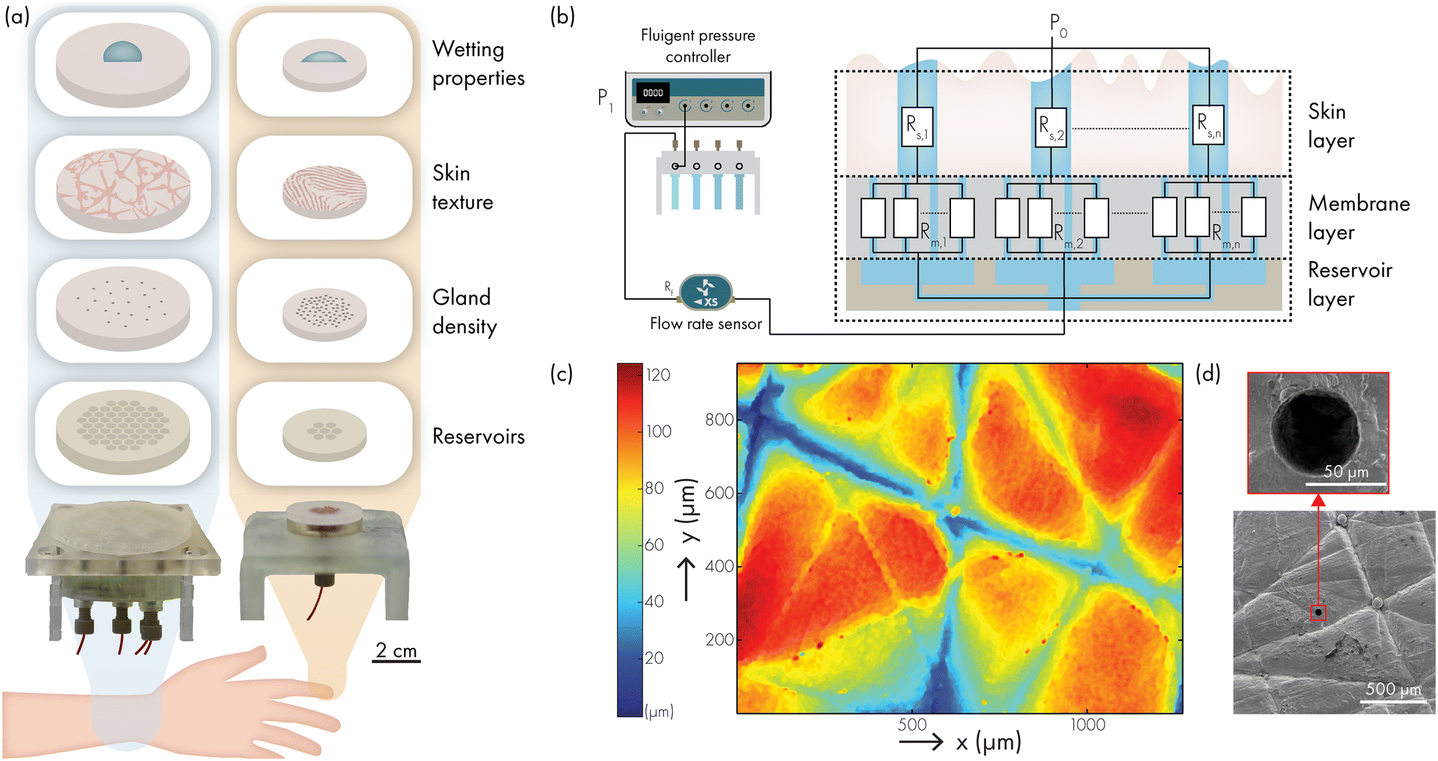 | ||
| Fig. 1 (a) Overview of the adaptable components of the artificial skin platform to mimic different targeted body locations, with schematic images of two artificial skin platforms mimicking finger and forearm sweat and skin characteristics. (b) Schematic overview of the working principle of our artificial skin platform. The pressure controlled actuation scheme for flow control via (multiple) reservoir(s) and flow sensor(s) gives stable control over the sweat rates and local sweat composition. The multilayered structure of the artificial skin platform consist of a skin layer with artificial sweat pores, a membrane layer with much smaller pores and a reservoir layer. (c and d) Artificial skin topography with artificial skin pore exits (diameter 60 μm). | ||
The artificial skin platform consists of three main layers, depicted in Fig. 1b: the reservoir layer, the membrane layer and the skin layer. To connect the skin layer to a fluid source, a reservoir layer is necessary. The topside of the reservoir layer consists of several hexagonal chambers of which the edges support the membrane and skin layer. These hexagonal chambers can be grouped with channels to form different reservoir sections in the reservoir layer and each section can be fed independently with artificial sweat as delivered by a separate fluid source. Each hexagonal chamber connects to several artificial sweat pores in the skin layer. This multi-reservoir design offers the possibility of inducing local variability in sweat content or concentration of certain biomarkers, and for controlling the number of active versus inactive sweat pores. Multiple reservoir sections can be controlled by replicating the number of reservoirs and flow sensors which are controlled by different channels of the pressure controller, or by incorporating fluidic switches to switch between different sections or reservoirs.
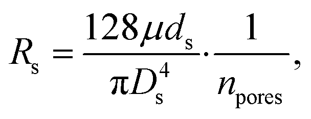
The second layer of the artificial skin platform is the membrane layer with high hydrodynamic resistance as compared to the pores of the artificial skin layer.3 Therefore, the pump pressure is increased substantially to maintain the required flow rate. Now, if a pore would not excrete, there is no flow through the part of the track etch membrane affiliated to this pore. No flow means no pressure drop and consequently the full pressure of the pump is present at this pore, immediately opening each blocked pore. Further, the membrane layer dominates the fluid pressure drop and therefore creates a constant flow through the sweat pores in the skin layer. The membrane layer consists of a hydrophilic track-etched polycarbonate membrane with pores of much smaller diameter and much higher areal density than the skin layer. Without this membrane layer, only a small number of pores with the lowest burst pressures will excrete with variable flow rate. Even small variations in pore diameter have a large effect on the hydrodynamic resistance of the pores.
The skin layer of the artificial skin platform is the third layer, made from silicone rubber. Different types of silicone can be used such that it resembles the skin Shore hardness and elasticity in different places of the body. By moulding these silicones against negative replicas of an actual skin surface, the exact topography and roughness of the skin are transferred to the skin layer of the artificial skin platform. Fig. 1c shows an optical surface profiler (Sensofar 2300 PLU) image of the topography of a skin layer moulded from the ventral forearm. The surface topography height shows variation between 0 to 100 μm and has a roughness average Ra of approximately 20 (Fig. S1†), which is similar to values reported in literature.8 Furthermore, scanning electron microscopy (SEM) images of the skin layer (Fig. 1d) confirm that the skin topography is replicated and that the artificial sweat ducts have a well-defined round opening with a diameter of 60 μm, which corresponds to the in vivo dimensions of 50–80 μm.7 The skin layer has a thickness of 3 mm, resembling the thickness of the dermis and epidermis and the length of the dermal duct of a sweat gland.7 The adaptable fabrication procedure allows for a variability in skin layer thickness, skin layer topography, number of artificial sweat pores and sweat pore distribution. Another important aspect in the development of an artificial skin platform for sweat sensor development is that the wetting properties of the skin layer need to match those of real human skin. In literature, contact angle measurements at different body locations have been reported.3,9–12 However, none of these articles describes the contact angle of the skin using sweat as test liquid. Therefore, we have also performed an exploratory investigation of the contact angle of sweat on human skin to investigate the desired wetting properties of artificial skin for development of sweat sensing devices.
Experimental
Fabrication of the skin layer
A complete illustration of the fabrication can be found in Fig. S2.† The skin layer is fabricated from silicone rubber, typically with Shore 15 (Resion Resin Technologies). The fabrication starts with making a negative skin replica by applying FINOSIL 22 (FINO) duplicating silicone over human skin and peeling it off once cured after about 15 minutes in ambient conditions. This skin replica is then sprayed with release agent (Mann Ease Release 2831) and dried before it is clamped in a poly(methyl methacrylate) (PMMA) casting mould. The casting mould contains spacers with 3 mm thickness creating a chamber between the negative skin replica and a flat piece of silicone. This structure is clamped between two so-called sweat pore pattern layers, which are PMMA sheets with CO2 laser machined holes at the desired sweat pore locations. In order to obtain sweat pores with a diameter of 60 μm diameter in the skin layer, molybdenum threads of 55 μm diameter are threaded through the casting mould, guided by the holes in the PMMA sweat pore pattern layers (Fig. S3†). Next, the chamber in the casting mould is filled with the skin layer silicone and left in an oven at 25 °C for 12 hours for curing. The skin layer is then demoulded.Bonding of the membrane layer to the skin layer
The membrane layer, shown schematically in Fig. 1b consist of a 25 μm thick straight pore hydrophilic polycarbonate track etched (PCTE) membrane with 0.2 μm diameter pores and a pore density of 5 × 10⁸ per cm2 (it4ip). Bonding this PCTE membrane to the silicone skin layer is not straightforward. The bond needs to be reasonably strong to sustain the pressure for actuation, the sweat pores in the skin layer as well as the pores in the PCTE membrane should not get clogged, and lastly the bonding process should not involve an alignment step in which errors can be made easily. Therefore, we use a stamping method with a thin layer of polydimethylsiloxane (PDMS) to successfully bond the membrane layer with the skin layer without blocking the pores. PDMS prepolymer with curing agent (10![[thin space (1/6-em)]](https://www.rsc.org/images/entities/char_2009.gif) :1 ratio, Dow Corning SYLGARD 184) and an additional catalyst 0.2 wt% Ashby–Karstedt (2% Pt(0) in cyclomethylvinylsiloxanes, Gelest) are mixed thoroughly and degassed. A thin layer of the uncured PDMS is first pasted, using a round 3 mm glass rod, on a cured PDMS layer of around 250 micrometers while maintaining a uniform thickness of a few micrometers. The pasted layer is then placed on the plasma-activated (30 s, 50 sccm O2, 20 W) skin layer and lifted off to transfer the thin film of uncured PDMS while leaving the pores in the skin layer open. The PCTE membrane is then placed on this uncured PDMS layer and left at room temperature for several hours, which cures the PDMS and bonds the membrane to the skin layer. Due to the PDMS-stamping process, a ring void of PDMS forms around the artificial skin pores which is approximately 2–3 times larger than the pore diameter (Fig. S2 and S4†).
:1 ratio, Dow Corning SYLGARD 184) and an additional catalyst 0.2 wt% Ashby–Karstedt (2% Pt(0) in cyclomethylvinylsiloxanes, Gelest) are mixed thoroughly and degassed. A thin layer of the uncured PDMS is first pasted, using a round 3 mm glass rod, on a cured PDMS layer of around 250 micrometers while maintaining a uniform thickness of a few micrometers. The pasted layer is then placed on the plasma-activated (30 s, 50 sccm O2, 20 W) skin layer and lifted off to transfer the thin film of uncured PDMS while leaving the pores in the skin layer open. The PCTE membrane is then placed on this uncured PDMS layer and left at room temperature for several hours, which cures the PDMS and bonds the membrane to the skin layer. Due to the PDMS-stamping process, a ring void of PDMS forms around the artificial skin pores which is approximately 2–3 times larger than the pore diameter (Fig. S2 and S4†).
Fluidic actuation of the artificial skin
The reservoir layer, indicated in Fig. 1b is made from clear resin using a Form 3 SLA printer (Formlabs). A laser cut double sided tape (3M 9087) is used to bond the reservoir layer to the plasma-activated membrane layer (30 s, 50 sccm O2, 20 W). An MFCS-EZ pressure controller (Fluigent) is used to pressurise storage tubes containing the working liquid(s) which are each connected with tubing to the different sections of the reservoir layer. Alternatively, when a constant flow rate over all pores is desired, all sections can be connected to one storage tube as noted in Fig. 1b. An XS flow unit bidirectional microfluidic flow sensor (Fluigent) is used to enable feedback control of the flow during experiments. Fig. S5† shows a photograph of the full set-up in two different configurations.(Artificial) sweat/sebum formulation
In all dynamic flow characterisation experiments DI-water was used as a reasonable proxy for sweat. For increased visibility the DI water was coloured using food dye (Bakiez). Artificial sebum according to the BEY formulation was ordered from Center For Testmaterials (The Netherlands). Sweat was obtained from volunteers using the Macroduct Sweat Collection System (ELITechGroup) in accordance with the protocol (Ref:ERB2021ME3) as approved by the Ethical Review Board (ERB) of Eindhoven University of Technology. All subjects provided written informed consent.Contact angle measurements
Static contact angle measurements were executed by recording images at a 90° angle using a Keyence VHX-5000 microscope. The images were subsequently analysed using ImageJ and the LB-ADSA plug-in.13 The study on human volunteers was conducted according to approval from the Ethical Review Board (ERB) at Eindhoven University of Technology in accordance with the protocol (Ref:ERB2022ME4). All subjects provided written informed consent. All participants (n = 7) were in the age group 20–35 years. In each measurement 3–5 data points per subject were taken.Results and discussion
Wetting properties of human skin
The wetting behaviour of the human skin has a broad variability, which is primarily caused by the skin topography and the amount of sebum present on the skin.9,10 After cleaning the skin, the static contact angle of water on the skin surface can be as high as 115°, whilst the contact angle in sebum rich areas, like the forehead, can be as low as 50°. However, none of the reported studies describes the contact angle of the skin using sweat as characterisation liquid. Therefore, we performed static contact angle measurements on the fingertip and the ventral forearm with DI water as well as human sweat. The contact angles were measured before and after cleaning of the skin with soap and acetone. The results of the measurements on cleaned skin are presented in Fig. 2a. Tabulated data, the pre-cleaning results and the results per individual person can be found in Table S1, Fig. S6 and S7.† This experiment gives insightful information for the development of the artificial skin platform. Firstly, the variability between persons and for individuals is large, indicated by a standard deviation of 8°, 11°, 12° and 17° with average contact angles of 97.4°, 76.4°, 84.4°, and 56.1° for each respective category (arm water, arm sweat, finger water, finger sweat). This wide variability is in agreement with literature,9–12 and it is one of the reasons why a well controlled artificial skin platform for sweat sensor development is necessary. Secondly, the contact angle of sweat is on average 24.7° lower than that of DI water. It is therefore important to consider the wetting characteristics of sweat when developing artificial skins as well as when developing wearable sweat sensing devices. Thirdly, the static contact angle of the skin on the finger is lower than that on the forearm and is thus different for different body locations. Whether this is due to the topography of the skin or other parameters cannot be concluded from this explorative study, but it does confirm that it is important to use a tailored artificial skin which mimics the target body location for the sweat sensing device.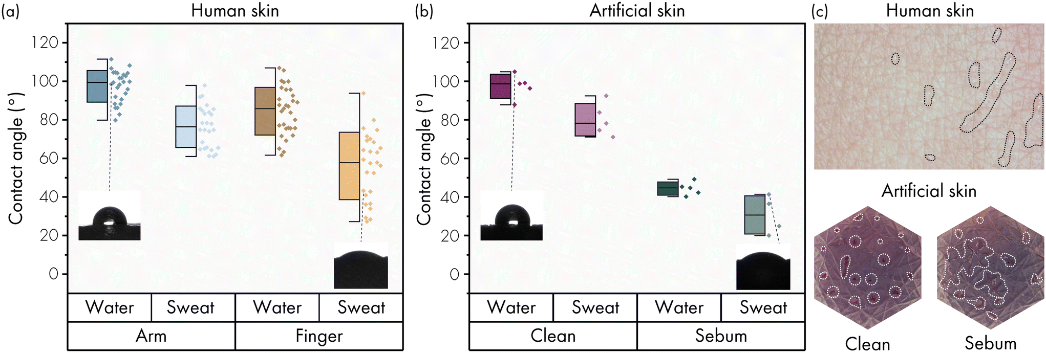 | ||
| Fig. 2 Wetting properties of human and artificial skin. (a) Static contact angles of water and sweat on cleaned human skin on the ventral forearm and the fingertip (n = 7). Insets show droplet images for two measurements, one with high contact angle of water on forearm skin and one with low contact angle of sweat on fingertip. Box represents SD. (b) Static contact angles of water and sweat on artificial skin, with replicated forearm skin topography, with and without artificial sebum. The contact angle range of water and sweat on the human skin can be mimicked. Insets show droplet images at two similar positions with respect to the measurements on the human skin in (a). (c) Visual qualification of dynamic wetting properties on human skin (top) and artificial skin without (bottom left) and with artificial sebum (bottom right). In the top image, taken on the uncleaned ventral forearm, sweat (indicated with the dotted lines for visibility) spreads along the skin topography. On the clean artificial skin the excreted artificial sweat forms droplets on the surface, while when artificial sebum is present on the surface of the artificial skin layer, it spreads along the skin topography, which mimics the specific situation on the human skin as shown in the top image. | ||
Wetting properties of artificial skin
The static contact angle of a surface is determined by the intrinsic bulk material properties, by surface modifications and by the topography of the surface. The choice of a silicone as skin layer material typically implies a hydrophobic contact angle, which means that simulating a hydrophilic skin would be difficult. Static contact angle measurements with DI water and sweat on the silicone skin layer respectively show a contact angle of 97.4 ± 6° and 80 ± 8° (Fig. 2b), corresponding well to the measured static contact angle on the cleaned human forearm with DI water and sweat (97.4 ± 8° and 76.4 ± 11°). However, the contact angles found in literature and our measurements on the cleaned finger using sweat are significantly lower (Fig. 2a). The article by Mavon et al.9 states that the skin surface can become hydrophilic due to the presence of sebum. Therefore, we investigated the application of artificial sebum as surface treatment to lower the contact angles to mimic the (more) hydrophilic skin conditions on for instance the finger. One mg cm−2 artificial sebum was applied to the surface of the silicone skin layer and spread evenly by rubbing with a glove. The application of artificial sebum lowered the static contact angle of DI water and sweat to 44.3 ± 3° and 30.6 ± 10°, as can be seen in Fig. 2b. By partly removing the sebum with a wipe and ethanol, the contact angles in between these two states can also be mimicked; the data of this experiment can be found in Fig. S8.† The surface of the silicone skin layer could be fully cleaned with soap and acetone, which restores the contact angle to the initial conditions. Quantitative measurements of the dynamic, rather than static, wetting properties of the artificial skin with and without sebum are difficult, especially at low flow rates. Visual inspection of the excreted liquid on top of the skin layer showed droplet formation when no sebum was present and spreading of liquid when sebum was applied before the start of the experiment, as shown in Fig. 2c. This process is similar to the spreading of sweat along the topography of the human skin when sebum is present, also shown in Fig. 2c.Dynamic behaviour of fluid flow
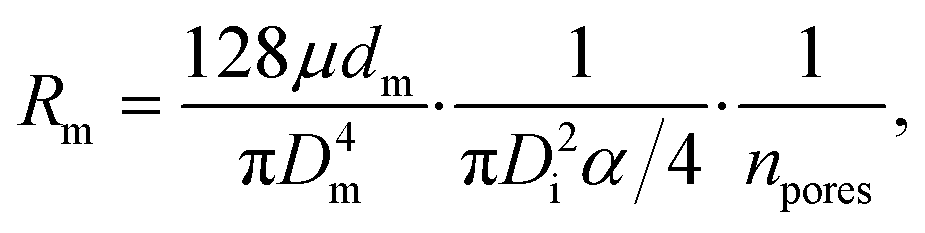
The flow through the artificial skin platform is controlled with active feedback using a flow sensor. We used an analytical model to predict the expected flow rate at set pressure to verify whether the platform behaves as expected and to validate the flow sensor read-out. The total flow rate Q through the artificial skin platform can be calculated using eqn (1):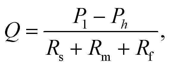 | (1) |
 | (2) |
 | (3) |
The Laplace pressure is neglected in these equations, which is only valid once the PCTE membrane and the artificial sweat pores in the skin layer are fully wetted. In order to achieve this, we (1) use a hydrophilic PVP-treated membrane which aids the filling of the PCTE membrane pores and (2) initially fill the artificial skin using 2% Micro-90 (International Products Corporation) soap solution which is subsequently removed and replaced by DI-water in overnight operation. Afterwards, the artificial skin can be used for prolonged time, if care is taken that no complete drying occurs.
Fig. 3a shows the overall flow rate Q through the artificial skin platform as a function of the applied pressure P1 in a comparison between the analytical model and the experimental data. The experimental results shown are from an artificial skin with 120 pores on a skin surface of 1.54 cm2 and they are in reasonable agreement with the theoretically expected results. The Fig. 3b shows the dynamic flow behaviour of the artificial skin platform under increasing and decreasing load. Every minute the flow rate is increased by 50 nL min−1 starting at 0 nL min−1 and going to 950 nL min−1. The inset figure shows a single step with the settling response of the flow rate; the settling time is smaller than 10 seconds and no overshoot is observed. Sweat glands in vivo can excrete sweat in a pulsating pattern, with active and inactive periods with a typical timescale of minutes.14,15 For the development of sensors that can cope with this pulsation, the artificial skin should also be able to secrete sweat in a pulsating pattern. Fig. 3c shows the actuation of the artificial skin with active/inactive periods of one minute with increasing and decreasing sweat rates. Even at these large flow rate steps, the settling time is within 10 seconds and no overshoot is observed, both for increase and decrease of the flow rate.
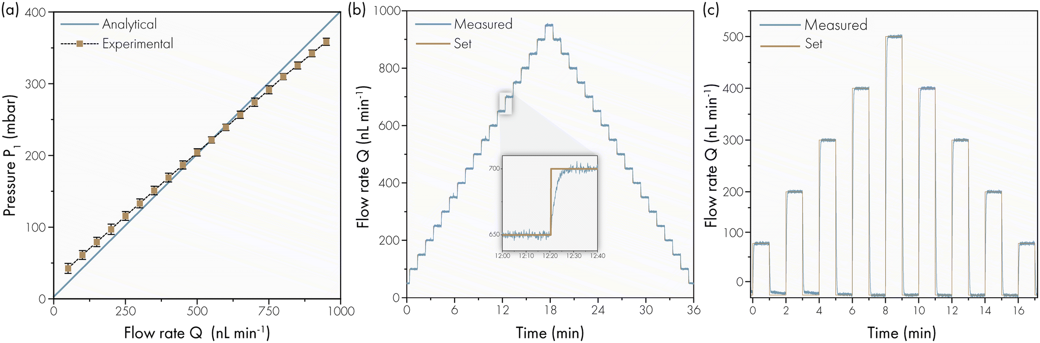 | ||
| Fig. 3 Overall dynamic flow behaviour of artificial skin platform with 120 active sweat pores measured at room temperature. (a) Analytical vs. experimental overall flow rates as a function of applied pressure; the pressure was increased in steps from low to high values and back again. The small error bars (n = 13) indicate repetitive results for both increasing and decreasing flow rates with low hysteresis. (b) Stepwise increase and decrease of flow rates. Inset shows a short settling time (<10 seconds) and the absence of overshoot. (c) Pulsating sweat secretion can be simulated using the artificial skin in a repetitive and controlled manner. | ||
The lower flow limit is determined by the smallest flow rate that can be measured by the flow sensor that is capable of measuring and controlling bulk flow rate down to 5 nL min−1. This results in an extremely low measurable flow rate per pore, equal to the bulk flow rate divided by the number of active sweat pores in the skin layer. The fabrication procedure allows for flexibility in the number of sweat pores; the lower limit is one, and the upper limit is 400 active pores cm−2. This higher limit is determined by the spacing between the wires during threading; the pitch can be reduced down to 500 μm. The upper limit of the flow rate is determined by the pressure the artificial skin platform can sustain before delamination of the double sided tape between the membrane and reservoir layer occurs. We tested pressures up to 500 mbar, resulting in sweat rates exceeding physiological values (depending on the number of active sweat pores). We performed experiments both at room temperature and at body temperature (37 °C), and observed no differences in flow performance. The presented results confirm that the artificial skin platform can deliver sweat patterns associated with sedentary state (0.1–1 nL min−1 gland−1) as well as heavy exercise and iontophoretic stimulation (1–20 nL min−1 gland−1), spanning the whole range of physiological sweat rates.16,17 We note that, when using the platform for a longer period, it is important to keep it activated at a low flow rate/pressure to make sure the pores do not dry or clog.
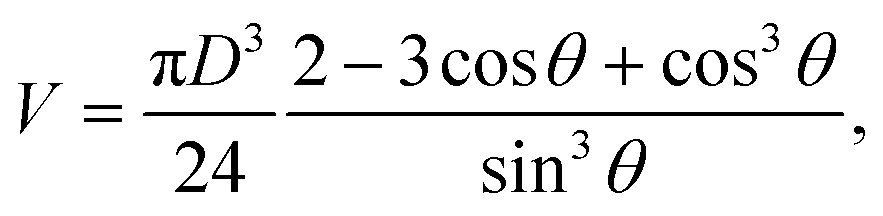
We also performed an optical analysis of the sweat droplet formation and the associated flow rate to determine (1) if the sensor readings are correct and (2) if the liquid that is passing the flow sensor is actually delivered to the top of the skin layer and is not taken up by yielding of the material or unnoticed minor leakage. A skin layer with 120 active pores and no skin topography was used to track the droplet growth over time at different flow rates. Pictures were taken every 10 seconds using a Canon EOS 80D camera. Fig. 4a and S10† show the droplet formation at 0, 5, 10 and 15 minutes from the start of actuation. At low flow rates, the evaporation limits the growth of visible droplets, as the surface of the artificial skin layer is fully exposed to the open air. At 500 nL min−1 (or ∼4 nL min−1 pore−1) and upwards the droplet growth can be optically examined. An image analysis via Matlab (details in Fig. S11†) was performed on one photo every minute for the flow rate of 1000 nL min−1, as at this flow rate the evaporation effects are minimal. In the image analysis the droplet area of each droplet is found and the diameter is calculated of a circle with the equivalent area. The droplet volume is then calculated using the following equation:18
 | (4) |
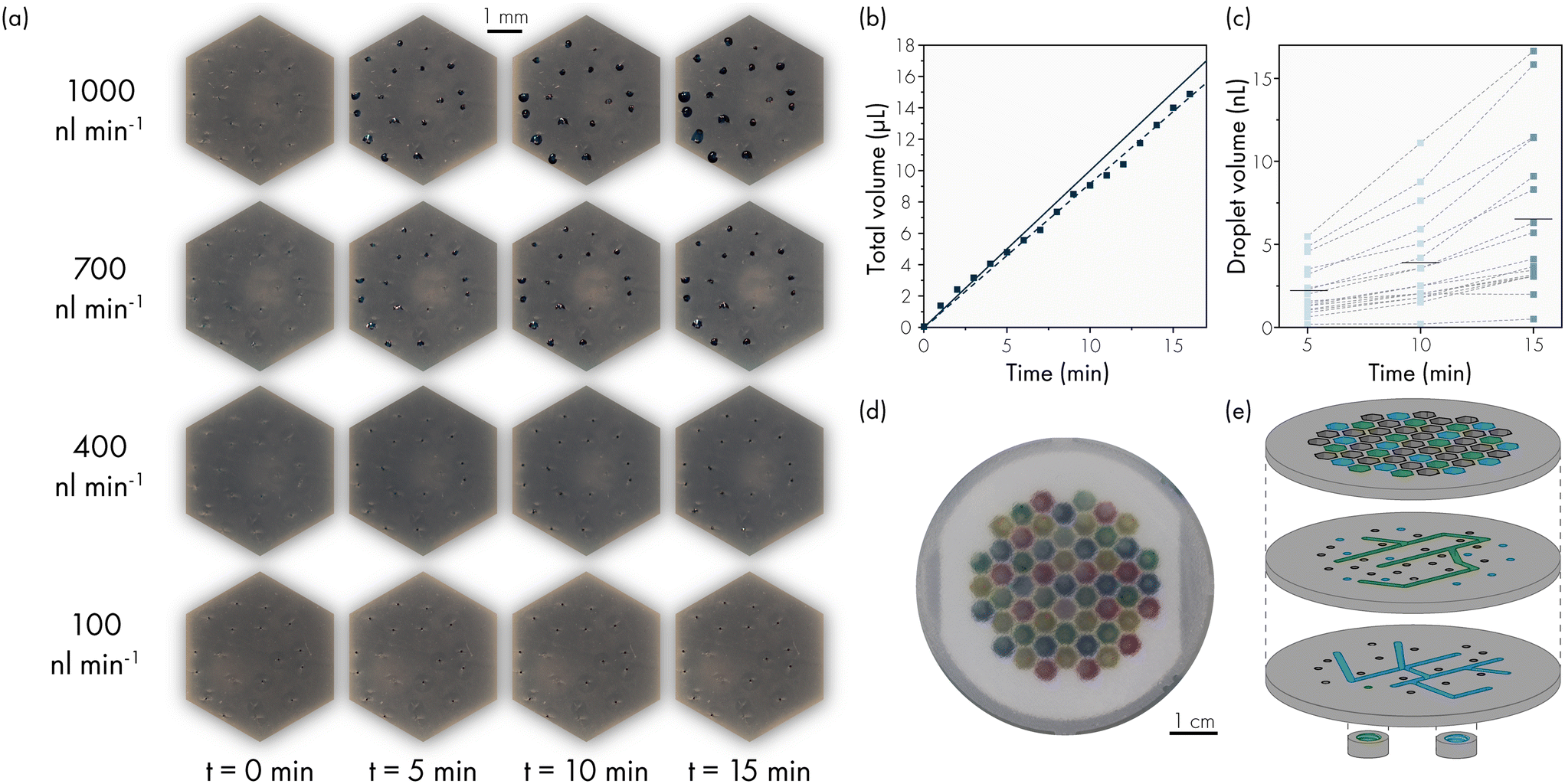 | ||
| Fig. 4 Visualisation of droplet formation and flow through the artificial skin. (a) Top view of one reservoir section from 0 to 15 minutes at overall flow rates ranging from 100 to 1000 nL min−1, corresponding to flow rates of 0.8 to 8 nL min−1 per pore. This skin layer has no skin topography to be able to visualise the droplet growth more clearly. Scale bar = 1 mm. (b) Image analysis results confirm the flow rate sensor results (solid line) for an overall set flow rate of 1000 nL min−1. Fitted curve (dotted line) f(y) = 917.3x with R2 = 0.9935. (c) Image analysis results to determine the sweat rate per pore for one reservoir at an overall set flow rate of 1000 nL min−1. The maximum difference between the most and least active pores stay within 2.5 times the mean flow rate. (d) Artificial skin platform with 55 hexagonal chambers actuated in four different sections with coloured DI water. The hexagonal chambers in the artificial skin platform can be grouped to change local sweat rate, active pore density and local sweat content concentrations. (e) Exploded view of top layer, two middle layers and the connections of the reservoir layer. The hexagonal chambers can be grouped by adding internal channels in the reservoir layer. Only two of the four channels are shown in the exploded view. | ||
To establish the flow rate variation between individual artificial sweat pores, we made an estimation of the flow rate per pore based on the images obtained. Fig. 4c shows the individual droplet volumes from the full images at 1000 nL min−1 in Fig. 4a at 5, 10 and 15 minutes. The results show a difference between the minimum and maximum value of 2.5 times the mean value. We have observed that this is not a random pattern but it is stable during the lifetime of the skin layer. The artificial sweat pores with higher flow rate keep excreting consistently at higher flow rate and vice versa. A cause for this difference in flowrate could be the variation of the size of the void between the skin layer and the membrane layer (Fig. S4†). Due to the PDMS-stamping process, a void forms around the artificial pores which is larger than the pore diameter. The membrane pores present within this interface are not clogged with PDMS and will thus contribute to the flow rate in the pore. In addition, the difference in flow rate per skin pore may be influenced by the variation in the number of pores per surface area of the PCTE membrane as well as the diameter of these pores. In practice, this means that the contribution of each sweat pore in eqn (3) may not be identical, and hence the flow rate may be different. Currently, no work has been described in literature in which the sweat rate per sweat gland was measured in a wearable device, but the sweat rate per area has been used as a sufficient measure.1 If development of a sweat sensing device requires a known sweat rate per gland as opposed to a sweat rate per surface area, the artificial skin platform can be characterised at the start of the experiments and the absolute sweat rate distribution per artificial sweat pore will then be known.
The reservoir layer can have multiple connections to grouped hexagonal chambers underneath the membrane and skin layer. These different groups can be actuated at different pressures, leading to different flow rates, or with different working liquids leading to local variation in artificial sweat chemical concentrations. This is demonstrated in Fig. 4d, showing an artificial skin platform with 55 hexagonal chambers actuated in four different sections with differently coloured DI water for visualisation. Fig. 4e shows an exploded view of the channels inside the reservoir layer. Each channel connects a different group of hexagonal chambers. The number of channel layers is dependent on the number of groups, Fig. 4e shows two of the four channels. Due to the scalable fabrication with a 3D resin printer, these channels as well as the thread for the microfluidic fitting can be incorporated in one printed part.
Conclusions
We have developed an artificial skin that can be used as a versatile test platform for the development of wearable sweat sensor devices and on-skin products such as deodorants, cosmetics, textiles and medical adhesives. The platform enables flexibility to mimic different body locations by means of altering the skin layer topography, number of active sweat pores, sweat gland density and wetting behaviour. The flow rate can be controlled to mimic sweat rates as low as 0.1 nl min−1 gland−1 and as high as 100 nl min−1 gland−1, including the physiological range for sedentary persons to persons doing heavy exercise. Furthermore, the platform allows for variation in the number of active sweat pores and in the regional sweat analyte concentrations during experiments by controlling separate reservoirs. The used fabrication techniques are simple and can be adapted towards the required number of sweat pores, skin layer size, skin layer thickness and silicone properties. The developed artificial skin should prove to be a valid test and verification platform towards the development of sweat patches for monitoring of (sedentary) persons.Author contributions
E. M.: conceptualisation, formal analysis, investigation, validation, visualisation, writing – original draft and writing – review & editing. T. U. I.: investigation, and writing – review & editing. S. K.: formal analysis and investigation. E. P.: conceptualisation, funding acquisition, supervision and writing – review & editing. J. H.: conceptualisation and writing – review & editing. J. D. T. conceptualisation, funding acquisition, supervision and writing – review & editing. All authors approved the final version of the article.Conflicts of interest
There are no conflicts to declare.Acknowledgements
This research is supported by the penta programme (project 19017). The authors would like to acknowledge Gilbert Verbeek and Walther Verberne for their help during the silicone replication.References
- E. J. Moonen, J. R. Haakma, E. Peri, E. Pelssers, M. Mischi and J. M. den Toonder, View, 2020, 1, 20200077 CrossRef.
- A. Koh, D. Kang, Y. Xue, S. Lee, R. M. Pielak, J. Kim, T. Hwang, S. Min, A. Banks, P. Bastien, M. C. Manco, L. Wang, K. R. Ammann, K. I. Jang, P. Won, S. Han, R. Ghaffari, U. Paik, M. J. Slepian, G. Balooch, Y. Huang and J. A. Rogers, Sci. Transl. Med., 2016, 8, 1–14 CrossRef.
- L. Hou, J. Hagen, X. Wang, I. Papautsky, R. Naik, N. Kelley-Loughnane and J. Heikenfeld, Lab Chip, 2013, 13, 1868–1875 RSC.
- A. Brueck, K. Bates, T. Wood, W. House, Z. Martinez, S. Peters, B. Root, K. Yelamarthi and T. Kaya, Electronics, 2019, 8, 15–17 CrossRef.
- J. Eiler, D. Hansen, B. Bingöl, K. Hansen, J. Heikenfeld and E. Thormann, Int. J. Adhes. Adhes., 2020, 99, 102574 CrossRef CAS.
- D. Hansen, S. Z. Moghaddam, J. Eiler, K. Hansen and E. Thormann, ACS Appl. Polym. Mater., 2020, 2, 1535–1542 CrossRef CAS.
- Z. Sonner, E. Wilder, J. Heikenfeld, G. Kasting, F. Beyette, D. Swaile, F. Sherman, J. Joyce, J. Hagen, N. Kelley-Loughnane and R. Naik, Biomicrofluidics, 2015, 9, 1–19 CrossRef.
- R. Maiti, L. C. Gerhardt, Z. S. Lee, R. A. Byers, D. Woods, J. A. Sanz-Herrera, S. E. Franklin, R. Lewis, S. J. Matcher and M. J. Carré, J. Mech. Behav. Biomed. Mater., 2016, 62, 556–569 CrossRef PubMed.
- A. Mavon, H. Zahouani, D. Redoules, P. Agache, Y. Gall and P. Humbert, Colloids Surf., B, 1997, 8, 147–155 CrossRef CAS.
- M. E. Ginn, C. M. Noyes and E. Jungermann, J. Colloid Interface Sci., 1968, 26, 146–151 CrossRef CAS PubMed.
- A. Elkhyat, C. Courderot-masuyer, S. Mac-mary, T. Gharbi and P. Humbert, Skin Research and Technology, 2004, 283–286 CrossRef PubMed.
- P. Capra, G. Musitelli and P. Perugini, Int. J. Cosmet. Sci., 2017, 39, 393–401 CrossRef CAS PubMed.
- C. A. Schneider, W. S. Rasband and K. W. Eliceiri, Nat. Methods, 2012, 9, 671–675 CrossRef CAS PubMed.
- T. Nishiyama, J. Sugenoya, T. Matsumoto and S. Iwase, Auton. Neurosci., 2001, 88, 117–126 CrossRef CAS PubMed.
- X. Chen, P. Gasecka, F. Formanek, J. B. Galey and H. Rigneault, Br. J. Dermatol., 2016, 174, 803–812 CrossRef CAS PubMed.
- N. A. Taylor and C. A. Machado-Moreira, Extreme Physiol. Med., 2013, 2, 4 CrossRef PubMed.
- P. Simmers, S. K. Li, G. Kasting and J. Heikenfeld, J. Dermatol. Sci., 2018, 89, 40–51 CrossRef CAS PubMed.
- A. Sommers and A. M. Jacobi, Int. J. Air-Cond. Refrig., 2008, 1–8 Search PubMed.
Footnote |
| † Electronic supplementary information (ESI) available. See DOI: https://doi.org/10.1039/d3lc00109a |
| This journal is © The Royal Society of Chemistry 2023 |