DOI:
10.1039/D2LC01147F
(Paper)
Lab Chip, 2023,
23, 1637-1648
Efficient AC electrothermal flow (ACET) on-chip for enhanced immunoassays†
Received
15th December 2022
, Accepted 3rd January 2023
First published on 16th January 2023
Abstract
Biochemical reaction rates in microfluidic systems are known to be limited by the diffusional transport of reagents, leading often to lowered sensitivity and/or longer detection times in immunoassays. Several methods, including electrically powering electrodes to generate AC electrothermal flow (ACET) on-chip, have been adopted to enhance the mass transport of the reagents and improve microfluidic mixing. Here, we report a novel ACET electrode design concept for generating in-plane microfluidic mixing vortices that act over a large volume close to the reaction surface of interest. This is different from the traditional ACET parallel electrode design that provides rather local vertical mixing vortices directly above the electrodes. Both numerical simulation and experimental studies were performed to validate the new design. Moreover, numerical simulation was carried out to show the effects of experimental factors such as the reaction kinetics (association constant) and the reagent concentration on the ACET-enhanced surface-based assays. As a proof of concept, the new design for the ACET-enhanced immunoassays was used to improve the immunostaining signal of the HER2 (human epidermal growth factor receptor 2) cancer biomarker on breast cancer cells. Finally, the concept of scaling up the design has been validated by experiments (immunoassays on breast cancer cells for different ACET power and different assay times). In particular, we show that larger ACET in-plane designs can agitate and mix the fluid over large microfluidic volumes, which further enhances the immunoassay's output. We have achieved a 6-times enhancement in the assay signal with a 75% reduction in assay time.
Introduction
Since the early development of microfluidic systems, they have been used in a plethora of applications such as medical diagnostics and biosensors,1 chemical synthesis,2 cell analysis,3,4 drug discovery, transcriptomics,5,6 and many other applications. This is triggered by the numerous advantages that microfluidics can offer, such as low reagent consumption, a high surface-to-volume ratio, the possibility of high-throughput analysis, and portability.7,8 In many surface-based assay techniques such as surface plasmon resonance sensing (SPR),9 immunohistochemistry (IHC),10 and fluorescence in situ hybridization (FISH),11 the bio-chemical reagents (DNA, antibodies, etc.) and the target sample (cells, tissues, etc. mounted on a substrate) are incubated inside the microfluidic chamber. During incubation, depending on the reaction kinetic rates, the reagents in the volumetric vicinity of the target sample are consumed, and a depletion region with a much lower concentration is formed over the sample.12–14 Unless the kinetic rates are the limiting factor, the reaction rate becomes limited by the transport of the reagents to the target sample, leading to lengthy experiments. Furthermore, the time for the mass transport of the reagents would further increase if the reagents also need to diffuse across the in-plane dimensions (x and y direction) in addition to the vertical transport (z). This limitation is highly present in applications that require analyzing and incubating large-size samples (mm and cm range) in thin chambers, such as the applications of microfluidics for tissue diagnostics.15–18 Tissue diagnostics using IHC and FISH are considered the golden standards for breast cancer diagnosis, one of the most deadly cancers in women, and have been approved by the United States Food and Drug Administration (FDA) for the assessment of protein level expression or gene copy counting respectively.19 Therefore, any improvement in the cost and time, and efficiency of these diagnostic techniques can be valuable. A wide range of theoretical and experimental methods have been investigated to enhance the microfluidic mixing and overcome the limited mass transport, such as the use of electro-hydrodynamics,20 electro-kinetics,21 magnetic stirring,22 vibrating membranes,23 acoustofluidic bubble cavitation,24 and pressure field modulation.25 Each of the different mixing technologies has its merits and each can be more adapted to a particular application. For example, acoustic vibrating structures can offer high mixing efficiency but require a complicated and lengthy micro-fabrication process and would typically require the resonance frequency matching of the attached piezoelectric device with the vibrating structure. Acoustic bubble cavitation similarly requires efficient bubble formation and trapping. Moreover, acoustic mixing may require high-voltage and high-frequency generators.26 Magnetic stirring can provide microfluidic mixing using magnetic beads or rods dispensed into the chamber, but would require a closely attached magnetic actuator, and might rely on the formation of bead chains,27 while hindering the optical readout if not interfering with the bio-chemical assays.28 AC electrothermal flow (ACET) is a technique from the AC electro-kinetics family that has been studied extensively and utilized for microfluidic mixing,12,29–31 pumping,32–34 trapping,35,36 and particle manipulation.37,38 Briefly, when a non-homogenous electric field is applied to a conductive fluid (i.e. a water-based sample with high ionic concentration as found in biological assays), temperature gradients are generated due to the Joule heating effect. These temperature gradients lead to local variations in the electrical conductivity and permittivity of the fluid, which can lead to a charge density gradient. The non-homogeneous electrical field acts on these charge gradients generating local fluid vortices. ACET can be suitable for biological assays since the latter are usually done in electrically conductive buffers. Thus higher ACET effects can be obtained in a more conductive fluid, but on the other hand the maximum allowable temperature is limited: a high temperature can lead not only to electrolysis and bubbles formation that can affect the experiments and lead to the electrodes deterioration, but can also affect the bioreagents' stability and functionality.31,39–41 On the contrary, some applications might benefit directly from the coupled effects of microfluidic mixing and the high temperature generated, such as thermal cycling for DNA amplification for PCR applications.42 Another disadvantage might be that the microelectrodes required for the ACET actuation can hinder the optical readout for different assays, but an alternative solution would be the usage of transparent conductors such as indium tin oxide (ITO).43 Most of the reported ACET literature work relied on the parallel electrode concept, where a pair of electrodes (or array of electrode pairs) is pulsed by an AC electric field.30,44–47 Doing so generates two counter-rotating vertical vortices above the electrodes, which can be used to replenish the bulk fluid above the target reaction surface. The ability of the rotating vortices to drag fresh reagents from regions away from the electrodes and thus replenishing more volumes is limited by the maximum electric field that can be applied in order not to increase excessively the generated temperature. The high-temperature region is usually localized in a small volume close to the electrode gap, where the electrical field strength is maximum and can cause several limitations as explained before. In addition, the parallel electrode design generates temperature along the full parallel length which leads to a local high average temperature. As an alternative, previous research efforts48,49 have shown a rotational in-plane fluid flow profile, but the system design had four large coplanar electrodes actuated with a four-phase AC signal to generate a rotating electric field thus increasing the complexity of the system.
To address these issues with ACET, we introduce a novel concept of electrode design that relies on having two tilted electrodes biased against a middle electrode with a singly-phased AC signal. This generates a three-dimensional fluidic motion with two in-plane counter-rotating vortices combined with vertical flow profiles. The in-plane motion is capable of increasingly refreshing the fluid over the reaction area from a large volume in the microfluidic chamber. Moreover, the new design, due to its increasing gap between the electrodes, possesses a lower average temperature as compared to the parallel design at the same voltage. We suggest that the reported work can serve as a basis for more efficient microfluidic mixing systems and their potential applications. We show the flow patterns using both numerical simulation and experiments with fluorescent micro- and nanoparticles. The numerical simulation also allows us to point out the importance of mass transport in regard to the reaction kinetics (association constant) and the reagent concentration, and the possible improvements enabled by microfluidic mixing. We then demonstrate the feasibility of the new ACET technique for the improved immunostaining of the HER2 tumor marker (human epidermal growth factor receptor2, also known as ERBB2) on cancer tissue slices. HER2 is overexpressed in 15–20% of breast cancer cases, causing rapid progression and poor prognosis of the disease.15 To the best of our knowledge, this is the first research that demonstrates ACET mixing for IHC-based diagnostics. Finally, we demonstrate the advantageous scaling of the proposed design, going for a larger mixing coverage area when using longer electrodes and a bigger gap between the electrodes, and demonstrate improved immunostaining of cancer cells thanks to the ACET-based microfluidic mixing.
Experimental setup
Our system relies on the use of a thin and wide microfluidic chamber that has been used before for studying cancer biomarkers on biological samples.10,11,16,50 The system uses a polymer chip (Fig. 1a) which provides fluidic accessibility to the chamber through multiple inlet holes (small white circles), and an imaging window in the middle of the chamber. The window is made of a glass coverslip on which the electrodes' microstructures are fabricated and face the inside of the fluidic chamber. Our novel in-plane vortex design has two electrodes tilted and biased against the middle electrode. The electrodes are interfaced with insulated electrical wires to a high voltage amplifier (WMA-300, Falco-system) that is connected to a function generator (AFG3021B, Tektronix), and the signal over the electrodes is monitored by an oscilloscope (54602B, HP). A rubber O-ring (Fig. 1b) is used to seal the area around the center window and prevent any fluid leakage. The polymer microfluidic chip is mounted inside the integrated system (Fig. 1c) and clamped against the lower sample part. The lower part of the system hosts the sample slide (glass microscopy slide carrying a thin section of biomaterial), which is located above the temperature-controlling system. Fig. 1d shows the core geometry of the setup that is used for the simulation, which consists of a microfluidic chamber (15 × 15 × 0.05 mm3) sandwiched between a glass coverslip with the electrode's microstructure and a bottom sample glass slide. All fluid handling and flow rate were controlled by an integrated pressure pumping system. All details of the immunoassay and fluorescence imaging and microfabrication protocols are described in the ESI† (supplementary protocols).
 |
| | Fig. 1 Experimental setup. (a) Top schematic view of the polymer chip used with the fluidic access holes (a larger white inlet hole diverging into multiple fluidic paths represented by red-dashed arrows to dispense the liquid into the chamber through the small white holes, similar for the outlet) and the microfabricated electrodes design on the glass coverslip (the design size is enlarged just for visual clarity). (b) Cross-sectional schematic side view of the experimental setup showing the polymer chip clamped against the sample slide with an O-ring that seals the microfluidic chamber (15 × 15 × 0.05 mm3) (c) 3D design of the integrated experimental setup with the polymer chip clamped against the sample (generally a glass microscope slide carrying a thin tissue section). The lower part of the setup has a heating system that controls the temperature of the setup. (d) Geometry of the 15 × 15 × 0.05 mm3 microfluidic chamber (blue) that is used into the simulation, which has an upper glass coverslip with the electrodes (black), a lower 1 mm-thick sample glass slide (white), and a PDMS spacer slab between both glass slides. The inset figure shows the newly introduced ACET electrodes design concept. | |
Numerical simulation
AC electrothermal flow
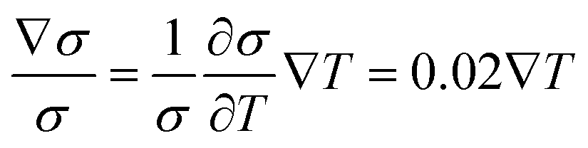
The 3D simulation was carried out using COMSOL Multiphysics (5.6) using the microfluidic design shown in Fig. 1d. The AC electrothermal flow originates from the temperature gradients in the bulk fluid, which are generated by the joule heating as a result of the electrical field applied to the electrically high conductive solution, as calculated by the energy balance eqn (1),31where E is the electric field magnitude, T is the temperature, k, and σ are the fluid thermal and electrical conductivities, respectively. The fluid electrical permittivity (ε) and conductivity (σ) are dependent on the temperature according to eqn (2) and (3),48,51| |  | (2) |
| |  | (3) |
The electrothermal flow is then formed due to the interaction of the conductivity and permittivity gradients with the electric field. The local electrical charge distribution, described by Gauss's law and charge conservation52 (eqn (4) and (5), respectively), responds to the electric field and exerts a momentum on the surrounding fluid where ρE is the space charge density.| |  | (5) |
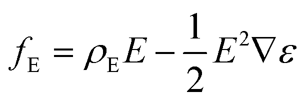
The electrical force applied to the charge density is shown in eqn (6),| |  | (6) |
where the first term ρEE denotes the Coulomb force and the second term 1/2E2∇ε denotes the dielectric force. As the charges move under the effect of the electric field, they drag the fluid. The Coulomb force dominates at low frequencies and the dielectric force dominates at high frequencies. For highly conductive solutions (e.g. 1 S m−1), the cross-over frequency between the coulomb and dielectric forces is close to the range of 200 MHz,30 and thus the electrothermal force is dominated by the Coulomb forces in our experiments (AC frequency = 1 MHz, fluid conductivity = 1.5 S m−1). The fluid motion can finally be obtained by solving the Navier–Stokes equation53 for low Reynolds number systems (eqn (7)) together with the mass conservation (eqn (8))The time-averaged electrothermal force per unit volume is shown in eqn (9),12,30,31| |  | (9) |
where τ = ε/σ is the charge relaxation time, and ω is the angular frequency of the electric field E.
Surface-based reaction rate and analyte transport
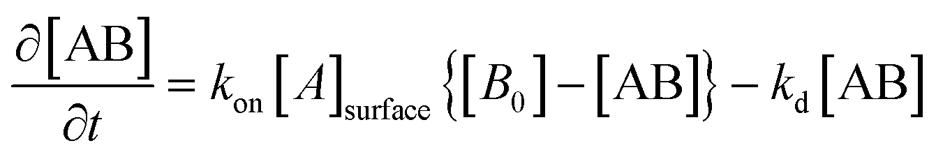
The reaction between the immobilized target on the surface and the diffusing analyte is assumed to follow a first-order Langmuir adsorption model.54 The molar concentration of the analyte-target complex [AB] being formed over the reaction time is related to the analyte concentration at the reaction surface Asurface, and to the target concentration B0 by the following eqn (10),12| |  | (10) |
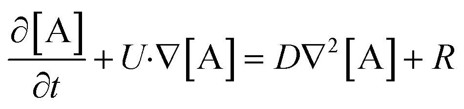
where kon, kd are the association and dissociation rate constants respectively. The initial target concentration used is B0 = 3.3 × 10⁻⁸ [mol m−2] and the dissociation constant kd = 10−2 [1/s], and the association constant kon was simulated for the range of kon = 103–105 [m3 s−1 mol−1]. The initial bulk analyte concentration available at the surface for reaction Asurface was simulated for the range of 10−6–10−11 [mol m−3]. This analyte concentration and the bulk fluid are replenished by the fluid flux according to Fick's second law of diffusion, as shown in eqn (11),12| |  | (11) |
where A is the concentration of the analyte in the bulk fluid, U is the fluid velocity, D is the diffusion coefficient of the analyte, and R is the reaction rate, which equals zero in the bulk fluid, as no reaction takes place in the fluid. Full details of the numerical simulation strategy (Fig. S5†) and the variables' values (Table S1†) and the boundary conditions (Table S2†) are explained in the ESI.† Moreover, our numerical model for the ACET and the enhanced surface-based assays has been benchmarked and validated with known numerical simulations and experimental results from the literature (ESI† Fig. S1 and S2). Finally, our numerical simulation for the ACET-enhanced surface-based assays has been also compared with an alternative published design with parallel electrodes55 at different electrodes' separations (ESI† Fig. S3).
Results & discussion
ACET in-plane vortex design flow patterns
Here, we show our results for the numerical simulation and experimental verification of the new in-plane vortex design. Fig. 2a shows the numerical simulation of the fluidic streamlines generated by the ACET actuation of the in-plane design. The design has two side electrodes biased and titled (45°) against the middle electrode, which creates localized mixing spots, as shown later. The in-plane motion pulls the fluid from the two sides of the design and pushes it to the center, where the two incoming directed fluid fluxes oppose each other and lead to an upward (top of design) directional motion. A closer look at the cross-section side view of the chamber in Fig. 2b shows straight lateral lines between each side electrode and the middle electrode, indicating the in-plane lateral motion. Further clarification of fluidic streamlines of the in-plane and vertical vortex design is shown in the ESI† (Fig. S5). The streamlines obtained by the new in-plane vortex design are different from the traditional design of parallel electrodes which provides mainly two counter-rotating vertical vortices above the biased electrodes. Fig. 2c shows the experimental verification of the fluidic motion generated by the new design. The superimposed tracing images of 1 μm-diameter fluorescent microparticles overlap with the simulation results, both in the vortices shape and the direction of fluid motion (Video S1†). Moreover, we also carried out a numerical simulation to validate how small nanoparticles (20 nm) move under the influence of the ACET in-plane motion, in resemblance to small-size reagent molecules. The simulation considers the (i) effect of the fluid drag forces on the microparticles by using the Stokes drag law, (ii) the effect of the temperature on the Brownian motion and the fluid dynamic viscosity, and finally (iii) gravitational forces. The results (ESI† Fig. S4) show that the particles follow the fluidic streamlines, with the particles located at the center of the design experiencing the strongest ACET fluidic motion. This is expected as the electric field is strongest in this central part.
 |
| | Fig. 2 Simulation and experimental results of in-plane vortex fluidic motion. (a) ACET fluidic streamlines obtained by the numerical simulation of the new electrode design, showing two large-area counter-rotating in-plane vortices. (b) Top-tilted and cross-sectional view of the fluidic streamlines at the design's centre. Arrows indicate the direction of the simulated flow streams. The blue rectangle at the bottom of chamber represents the surface reaction area (represented thicker for visual clarification, but in the simulation, it is a 2D surface) (c) fluidic streamlines obtained in an experimental verification of the new design. The figure shows superimposed images of a time sequence of 1 μm fluorescent microparticles moving along with the ACET in-plane vortices. | |
ACET-enhanced surface reaction (kinetics)
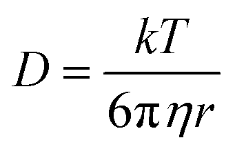
We have investigated the possibility of using the new in-plane vortex design for enhancing surface-based immunoassays (i.e. surface adsorption reactions) and studying the effects of experimental conditions, such as the association kinetic constant and the analyte concentration. At the beginning of the reaction, antigens in the target area start to consume the reagents available in their volumetric vicinity. After some time and depending on several factors, including the reaction kinetic rates and the reagent concentration, a depletion region is formed around the target area with a much lower availability of the analyte reagent (as shown later). At this point, the reaction rate becomes limited due to the scarcity of the detection reagents and their diffusion-limited transport. There are a variety of detection reagents (RNA, DNA, antibodies, aptamers, etc.) that can be used in different assays, and their diffusion time depends mainly on their size. eqn (12) shows the Stokes–Einstein relation56 between the diffusion coefficient (D) and the particle radius (r), where (T) is the absolute temperature, (η) is the solvent viscosity and (k) is the Boltzmann constant.| |  | (12) |
Eqn (13) shows the Einstein–Smoluchowski relation for the mean-square displacement of a diffusing particle,where x is the mean distance that a molecule with diffusion coefficient D will diffuse over time t. Here, we can see clearly that larger molecules will have a smaller diffusion coefficient and, as a result, would need longer times to diffuse over a given distance x. For instance, biological molecules such as antibodies and DNA have diffusion coefficients in the range of 10−11 to 10−12 m2 s−1 (ref. 57 and 58) and thus would need a diffusion time in the range of a few minutes to hours to travel across a distance of 100 μm, leading to long-time experiments. Here, the fluidic motion generated by the ACET clearly facilitates the transport of the analyte reagents inside the chamber and thus, enhances the replenishment of the reagent in the vicinity of the reaction surface.
Fig. 3a shows the enhancement in the surface adsorbed species (mol m−2) over a surface reaction area (circle with 100 μm radius) positioned at the center of the in-plane electrode design, as shown in Fig. 2b, for different applied voltages (Vpp) and different association constants Kon (m3 s−1 mol−1) and after a reaction time of 30 (minutes). It is clear that for a given association constant and with higher voltages (for example 15 Vppvs. 0 Vpp), the concentration of surface-bound reagent species is higher. This is mainly due to the increase in velocity of the generated ACET fluid motion and thus, faster replenishment of the analyte in the vicinity of the surface reaction area. Additionally, it shows that the ACET mixing effect at higher voltages can shorten the reaction time needed for immunoassays while obtaining higher detection signals. Moreover, it shows that for a given voltage (for example 15 Vpp, cyan color), the enhancement in the surface-bound concentration is lower for lower association constants, as the kinetic rate of the reaction, in this case, is the limiting factor. Therefore, there is a small room for improvement by mixing in the surface adsorbed species concentration (i.e., fluorescent detection signal) of biochemical reactions that have slow kinetic rates (i.e., small association constants).
 |
| | Fig. 3 Simulation of surface binding of reagents to the target antigens. (a) Enhancement in the surface-bound species (mol m−2) as a result of the ACET flow over a surface reaction area (circle of 100 μm radius centred at the tips of the 3 electrodes) for different applied voltages (0, 5, 10, 15 Vpp) and different association constants Kon (103, 104, and 105 (m3 s mol−1)) at an initial analyte concentration inside the chamber of 10−11 (mol m−3). (b) Enhancement factor for t = 30 minutes of the surface-bound species (15 Vpp/0 Vpp) at the different association constants, and at an initial analyte concentration inside the chamber of 10−11 and 10−6 (mol m−3). | |
Fig. 3b shows the enhancement factor defined by the enhanced surface concentration mol m−2 obtained at 15 Vpp over a surface concentration obtained at 0 Vpp (without ACET mixing), for an initial analyte concentration inside the chamber of 10−6 and 10−11 (mol m−3) at 30 minutes, respectively. This shows that the enhancement is higher for the lower (10−11 mol m−3) analyte concentration. This is mainly due to the scarcity of the analyte in the vicinity of the immobilized target, rendering the ACET microfluidic mixing more helpful in the replenishment of the analyte. In contrast to that, with high analyte concentration (10−6 mol m−3), there is an abundance of the analyte and thus, the ACET mixing enhancement is limited.
Comparison of in-plane versus vertical vortex design
The ACET technique has been studied in the past using the parallel electrodes configuration, where a pair of electrodes (or an array of electrode pairs) with specific width and an interspacing gap is located at the top/bottom of a microfluidic channel.12,29–31,34,44,47,59–61 The actuation of the electrodes with the AC electric field generates counter-rotating fluidic vortices in the z-direction above the electrodes' surface. This can help enhance the surface-based reaction by stirring the fresh analyte concentration and replenishing the depletion region formed over the target sample. The ability of the parallel electrode design to mix and thus enhance the surface reaction is limited by the temperature that can be generated not to degrade the biomolecules. Also, a high electric field can lead to electrolysis and the formation of bubbles.31 It has been reported that high ACET voltages applied to 0.5 S m−1 conductive solution (1/3 of buffer conductivity used in the current work), would indeed lead to electrolysis and bubbles.39 Moreover, the stability and functionality of the bioreagents can be sensitive to high temperatures.40,41 Here we show the ability of the new in-plane vortex design to enhance the analyte concentration replenishment by obtaining a large in-plane volumetric mixing. We have carried out a comparison of the performance of the in-plane design versus the vertical vortex design. As previously discussed in the theoretical section, the ACET-induced flow and thus the mixing enhancement is defined by the electric field and the resulting temperature profile. Both variables are highly dependent on the microelectrodes' design and operation. Therefore, to highlight the role of ACET-induced transport when comparing the in-plane and the vertical designs, the generated average temperature in the volume centered around the electrode gaps was kept the same for both designs. Our in-plane vortex design has 50 μm wide electrodes with the two side electrodes spaced 85 μm and tilted 45° against the middle electrode. Similarly, our classical vertical vortex design has 50 μm wide electrodes spaced 85 μm against the middle electrode at a 90° angle. A full comparison of the fluidic streamline vortices of the in-plane and vertical designs is shown in the ESI† (Fig. S5).
Fig. 4a shows the simulation results of the enhancement of the surface adsorbed species by the in-plane and vertical vortex electrode designs at the same volumetric average temperature. This shows that the in-plane vortex design enhances the surface reaction better than the vertical vortex design. This is further confirmed by Fig. 4b, which shows a time series of bulk analyte concentrations obtained by mixing using the two designs. The depletion region over the reaction surface located at the bottom of the chamber (Fig. 2b) is allowed to form initially (t1 to t2), and thereafter the ACET actuation was applied (t3). The period (t3 to t4) shows how both designs can replenish and direct the fresh analyte molecules to the reaction surface. Additionally, it shows that the semi-circular in-plane vortices resulting from the new in-plane electrode design result in a larger mixing area (meaning a higher surface reaction) as compared to the parallel vertical design. A similar extent of the in-plane fluid mixing is observed by experiments as seen in Video S1† and Fig. 2c.
 |
| | Fig. 4 Comparison of the in-plane versus the vertical vortex design for enhancing surface-based assays. (a) Enhancement in the surface-bound species (mol m−2) as a function of reaction time as a result of the ACET flow for the in-plane and the vertical vortex design at two different temperatures (29.75 °C, and 32.0 °C). The association constant is 104 (m3 s−1 mol −1) and the initial analyte concentration inside the chamber is 10−8 (mol m−3). (b) Development of the depletion region during the reaction. The depletion region was allowed to form until time (t2 = 24.983 min), and the ACET actuation was only applied at time (t3 = 25.183 min) to show how both designs would mix and replenish the analyte concentration above the central region (t4 = 25.683 min). | |
ACET-enhanced immunoassay
Experimental verification was carried out to compare the two designs using the immunoassay protocol described in the ESI.† Briefly, BT-474 cancer cell pellet sections were incubated with rabbit primary anti-HER2 antibodies and then anti-rabbit secondary antibodies conjugated with biotin molecules. Then, the sections were incubated with streptavidin molecules conjugated with 647 fluorescent dye. ACET was applied only during the primary and secondary antibodies incubation. Finally, the sections were mounted and imaged using an automatic fluorescent scanning system. The signal (S) and background (B) values of the ACET (area located below the ACET electrodes) and non-ACET (far away from the electrodes) cell fluorescent spots were measured and analysed, as explained in the ESI.† The average (n = 3) enhancement factor due to the ACET mixing over static reaction (non-ACET) was calculated using the following eqn (14), where τ is the exposure time of the fluorescence excitation signal used in the experiment:| |  | (14) |
Fig. 5a shows representative gradient map images of the BT-474 cells' immunostaining signal for the in-plane and vertical vortex ACET-enhanced mixing versus the unenhanced (non-ACET) images. A schematic of the corresponding locations of the ACET and non-ACET spots within the microfluidic chamber and in relation to the ACET electrode's design is shown in detail in the ESI† (Fig. S6). Here, the HER2 signal is enhanced in the ACET versus the non-ACET images and is more prominent in the cellular membrane. Fig. 5b shows the average enhancement of immunofluorescent staining at the ACET mixing location over the normal non-ACET incubation. It shows that both designs, tested at two different temperatures, enhance the immunofluorescent reaction by replenishing the analyte concentration, especially when using higher voltages, as explained before. Furthermore, it shows that the in-plane vortex design can further enhance the immunoreaction due to its improved mixing ability. In parallel to that and as shown by simulation (Fig. 3b), with a higher dilution of the reagents, there is more scarcity of the analyte in the vicinity of the immobilized target and thus the ACET mixing can be more effective for enhancing the immunoreaction. This is shown by the results (Fig. 5b) of the ACET mixing using the two designs with 1![[thin space (1/6-em)]](https://www.rsc.org/images/entities/char_2009.gif) :500 dilution of primary and secondary antibodies. The in-plane and vertical design improved the immunostaining by 49.7% and 24.8%, respectively, which is higher than the performance of the same designs at the reagent's dilution ratio of 1:100. This shows the potential of using the new in-plane design for enhancing the outcome of chemical and bioassays.
:500 dilution of primary and secondary antibodies. The in-plane and vertical design improved the immunostaining by 49.7% and 24.8%, respectively, which is higher than the performance of the same designs at the reagent's dilution ratio of 1:100. This shows the potential of using the new in-plane design for enhancing the outcome of chemical and bioassays.
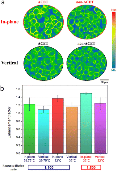 |
| | Fig. 5 Experimental validation for the ACET immunostaining enhancement using the in-plane and vertical vortex designs. (a) Gradient map images of the in-plane and vertical vortex enhanced fluorescent immunostaining on BT-474 cells. (b) Enhancement in the HER2 staining signal using the in-plane and vertical designs at two different average volumetric temperatures of 29.75 °C (1:100 dilution of primary and secondary antibodies) and 32.0 °C with (1:500 dilution of primary and secondary antibodies). | |
Improved in-plane design: scaling up
After validating the in-plane concept of design, and while it was seen that the in-plane design is capable of mixing the fluid over a larger area, we further investigated the concept of scaling up the design. The strategy was to enable the fluid agitation by the ACET motion over a larger area and thus enhance the fluid flow over the sectioned cells' surface. In case the parallel electrodes' design is used, additional parallel electrodes would be required to mix over a larger area, possibly compromising imaging accessibility. So, here we scaled up the in-plane design by extending the two side electrodes (200 μm to 1000 μm) and the middle electrode (450 μm to 1500 μm) and increased the gap between the electrodes from 85 μm to 340 μm. We confirmed that the up-scaled in-plane design was able to generate a larger mixing area while maintaining the same in-plane ACET motion (Video S2†). Superimposed tracing images of the small and large in-plane designs are shown in ESI† (Fig. S7), and the corresponding maximum temperature achieved by both designs at 30 Vpp is shown in ESI† (Fig. S8). Moreover, the temperature generated by the large in-plane design ACET actuation at different fluid electrical conductivities (0.75, 1, 1.25, and 1.5 S m−1) and with different ACET power (electrical currents of 9, 12, 15, and 18 mArms) was tested and reported in the ESI† (Fig. S9). Fig. 6a shows the enhancement in the BT-474 cells immunostaining at different ACET power. It shows an increased HER2 signal (green color) with the increasing ACET power due to the increased fluid mixing and the larger volumes being replenished over the assay's reactive surface. The images shown in Fig. 6a are the spots with the highest observed enhancement in the HER2 signal, which is usually the area located below the center of the electrodes' design. We have simulated how the location of the surface reaction spots in relation to the in-plane design can be affected by the ACET enhancement to different extents, as compared to the static non-ACET incubation (ESI† (Fig. S10)). It was found that the areas located close to the design center experience the highest enhancement in the surface reaction. This is mainly due to the close gap between the electrodes at that location and thus the strongest ACET forces. The order of enhancement for other surface reaction locations was the following (bottom > right and left > top of the design). Fig. 6b shows the analysis of the immunostaining enhancement factor as described before and using eqn (14) at different ACET power from 9 to 18 mArms. It shows enhancement factors of up to 5.5 and 8 can be achieved with 15 and 18 mArms respectively, while even the lowest power used (9 mArms) can still achieve a higher signal than the non-ACET reactive surface (static incubation). Moreover, with higher ACET power, the area affected by the enhanced ACET mixing is larger due to the stronger ACET forces and thus the fluid is agitated over larger areas. We believe that this would be practically useful for applications with large microfluidic chamber sizes and large samples, and in case maximum microscopic imaging accessibility is desired. It is worth noting that when higher ACET power (in the range of 18–20 mArms) was used, bubbles were generated due to the high temperatures and possibly electrolysis. Fig. 6c shows the analysis of the HER2 immunostaining enhancement factor for different incubation times, ranging from 2 to 8 minutes. It shows that enhancement factors of up to 13.2 and 15.9 can be achieved with 6 and 8 minutes of incubation respectively. Thus, with longer ACET actuation times, a further enhancement can be achieved. The inset plot of Fig. 6c shows the enhancement obtained with the ACET actuation for 2, 4, and 6 minutes over the static incubation (non-ACET) obtained after 8 minutes [(S − B)ACET(2,4,6min)/(S − B)non-ACET(8min)]. It shows that the incubation times can be shortened from 8 minutes down to 2 minutes (75% reduction in time) while still achieving 6 times higher signal. This can be valuable for reducing the experimental assay times and having faster diagnostics.
 |
| | Fig. 6 The ACET immunostaining enhancement using the up-scaled in-plane design. (a) Representative images of the ACET enhanced and the non-ACET (static incubation) immunostaining of BT-474 cancel cells using the up-scaled in-plane design at different ACET power (electrical current 9 to 18 mArms). Blue colour is the cell nuclei counterstaining (DAPI) and the green colour is the HER2 signal. (b) Enhancement in the HER2 staining signal using the up-scaled in-plane design at different ACET power for 2 minutes. (c) Enhancement in the HER2 staining signal using the up-scaled in-plane design for different incubation times (2 to 8 minutes) at an ACET power of 18 mArms. The inset plot of Fig. (6c) shows the enhancement of the HER2 signal with 2, 4, and 6 minutes of ACET mixing over the non-ACET (static incubation) staining with 8 minutes. Error bars represent the standard deviation (n = 3). | |
Conclusions
A novel electrode design leading to more efficient ACET-induced flow patterns and improved immunoassays has been presented. The design has two commonly side electrodes biased and tilted versus a middle electrode to generate two counter-rotating in-plane fluidic vortices. We demonstrated that the new design can provide microfluidic mixing over an increased volume in a microfluidic cell, leading to an enhanced reaction between the reagents in the fluid and the target antigen surface. Both numerical simulation and experimental validation have been used to illustrate the working concept of the new design. Additionally, numerical simulation of the ACET-enhanced surface-based assay has been shown. Moreover, the interplay between experimental conditions (association constant of the reaction, reagent concentration) and the ability of the microfluidic mixing to enhance surface-based reactions has been illustrated. In parallel to that, a comparison with a more traditional ACET parallel electrodes design was investigated. Furthermore, an experimental proof of concept of the ACET-enhanced immunofluorescent staining on cancer cells was shown. Moreover, the design concept has been investigated, both by simulation and experiments, on its scalability potential: larger designs (longer electrodes and larger gaps) are capable of fluid mixing over larger microfluidic volumes and thus enhance further the immunoassays. This effectively led to an enhancement of 6 times in the assay output signal and a 75% reduction in the assay time. This can be valuable for having more accurate and faster diagnostics.
Author contributions
Conceptualization: M. D., D. D., M. G., simulation: M. D., K. U., experimental investigation: M. D., data curation: M. D., K. U., visualization: M. D., writing original draft: M. D., editing: M. D., K. U., D. D., M. G., supervision: D. D., M. G.
Conflicts of interest
D. D. and M. G. have an interest in the company Lunaphore Technologies.
Acknowledgements
This project has received funding from the European Union's Horizon 2020 research and innovation programme under the Marie Skłodowska-Curie grant agreement No. 754354. We thank the Center of MicroNanoTechnology – EPFL for their help with the microfabrication. We also thank Pino Bordignon (Lunaphore Technologies SA) for his feedback with the experiments.
Notes and references
- C. Rivet, H. Lee, A. Hirsch, S. Hamilton and H. Lu, Microfluidics for medical diagnostics and biosensors, Chem. Eng. Sci., 2011, 66, 1490–1507 CrossRef CAS.
- Y. Liu and X. Jiang, Why microfluidics? Merits and trends in chemical synthesis, Lab Chip, 2017, 17, 3960–3978 RSC.
- M. Junkin and S. Tay, Microfluidic single-cell analysis for systems immunology, Lab Chip, 2014, 14, 1246–1260 RSC.
- H. Yin and D. Marshall, Microfluidics for single cell analysis, Curr. Opin. Biotechnol., 2012, 23, 110–119 CrossRef CAS PubMed.
- N. Shembekar, C. Chaipan, R. Utharala and C. A. Merten, Droplet-based microfluidics in drug discovery, transcriptomics and high-throughput molecular genetics, Lab Chip, 2016, 16, 1314–1331 RSC.
- F. Eduati, R. Utharala, D. Madhavan, U. P. Neumann, T. Longerich and T. Cramer,
et al., A microfluidics platform for combinatorial drug screening on cancer biopsies, Nat. Commun., 2018, 9, 2434 CrossRef PubMed.
- E. Samiei, M. Tabrizian and M. Hoorfar, A review of digital microfluidics as portable platforms for lab-on a-chip applications, Lab Chip, 2016, 16, 2376–2396 RSC.
- V. Ortseifen, M. Viefhues, L. Wobbe and A. Grünberger, Microfluidics for Biotechnology: Bridging Gaps to Foster Microfluidic Applications, Front. Bioeng. Biotechnol., 2020, 8, 589074 CrossRef PubMed , Available from: https://www.frontiersin.org/article/10.3389/fbioe.2020.589074.
- D. S. Wang and S. K. Fan, Microfluidic Surface Plasmon Resonance Sensors: From Principles to Point-of-Care Applications, Sensors, 2016, 16, 1175 CrossRef PubMed.
- A. T. Ciftlik, H. A. Lehr and M. A. M. Gijs, Microfluidic processor allows rapid HER2 immunohistochemistry of breast carcinomas and significantly reduces ambiguous (2+) read-outs, Proc. Natl. Acad. Sci. U. S. A., 2013, 110, 5363–5368 CrossRef CAS PubMed.
- H. T. Nguyen, R. Trouillon, S. Matsuoka, M. Fiche, L. d. Leval and B. Bisig,
et al., Microfluidics-assisted fluorescence in situ hybridization for advantageous human epidermal growth factor receptor 2 assessment in breast cancer, Lab. Invest., 2017, 97, 93–103 CrossRef CAS PubMed.
- M. Sigurdson, D. Wang and C. D. Meinhart, Electrothermal stirring for heterogeneous immunoassays, Lab Chip, 2005, 5, 1366–1373 RSC.
- D. Han and J. K. Park, Optoelectrofluidic enhanced immunoreaction based on optically-induced dynamic AC electroosmosis, Lab Chip, 2016, 16, 1189–1196 RSC.
- C. K. Yang, J. S. Chang, S. D. Chao and K. C. Wu, Effects of diffusion boundary layer on reaction kinetics of immunoassay in a biosensor, J. Appl. Phys., 2008, 103, 084702 CrossRef.
- H. T. Nguyen, D. Migliozzi, B. Bisig, L. de Leval and M. A. M. Gijs, High-content, cell-by-cell assessment of HER2 overexpression and amplification: a tool for intratumoral heterogeneity detection in breast cancer, Lab. Invest., 2019, 99, 722–732 CrossRef CAS PubMed.
- H. T. Nguyen, L. N. Dupont, E. A. Cuttaz, A. M. Jean, R. Trouillon and M. A. M. Gijs, Breast cancer HER2 analysis by extra-short incubation microfluidics-assisted fluorescence in situ hybridization (ESIMA FISH), Microelectron. Eng., 2018, 189, 33–38 CrossRef CAS.
- M. S. Kim, T. Kim, S. Y. Kong, S. Kwon, C. Y. Bae and J. Choi,
et al., Breast Cancer Diagnosis Using a Microfluidic Multiplexed Immunohistochemistry Platform, PLoS One, 2010, 5, e10441 CrossRef PubMed.
- M. S. Kim, S. Kwon, T. Kim, E. S. Lee and J. K. Park, Quantitative proteomic profiling of breast cancers using a multiplexed microfluidic platform for immunohistochemistry and immunocytochemistry, Biomaterials, 2011, 32, 1396–1403 CrossRef CAS PubMed.
- Z. Varga, A. Noske, C. Ramach, B. Padberg and H. Moch, Assessment of HER2 status in breast cancer: overall positivity rate and accuracy by fluorescence in situ hybridization and immunohistochemistry in a single institution over 12 years: a quality control study, BMC Cancer, 2013, 13, 615 CrossRef PubMed.
- A. O. E. Moctar, N. Aubry and J. Batton, Electro-hydrodynamic micro-fluidic mixer, Lab Chip, 2003, 3, 273–280 RSC.
- M. H. Oddy, J. G. Santiago and J. C. Mikkelsen, Electrokinetic Instability Micromixing, Anal. Chem., 2001, 73, 5822–5832 CrossRef CAS PubMed.
- M. Chang, J. L. F. Gabayno, R. Ye, K. W. Huang and Y. J. Chang, Mixing efficiency enhancing in micromixer by controlled magnetic stirring of Fe3O4 nanomaterial, Microsyst. Technol., 2017, 23, 457–463 CrossRef CAS.
- H. V. Phan, M. B. Coşkun, M. Şeşen, G. Pandraud, A. Neild and T. Alan, Vibrating membrane with discontinuities for rapid and efficient microfluidic mixing, Lab Chip, 2015, 15, 4206–4216 RSC.
- A. Ozcelik, D. Ahmed, Y. Xie, N. Nama, Z. Qu and A. A. Nawaz,
et al., An Acoustofluidic Micromixer via Bubble Inception and Cavitation from Microchannel Sidewalls, Anal. Chem., 2014, 86, 5083–5088 CrossRef CAS PubMed.
- Q. Xia and S. Zhong, Liquid mixing enhanced by pulse width modulation in a Y-shaped jet configuration, Fluid Dyn. Res., 2013, 45, 025504 CrossRef.
- C. Y. Lee, C. L. Chang, Y. N. Wang and L. M. Fu, Microfluidic Mixing: A Review, Int. J. Mol. Sci., 2011, 12, 3263–3287 CrossRef CAS PubMed.
- S. H. Lee, D. van Noort, J. Y. Lee, B. T. Zhang and T. H. Park, Effective mixing in a microfluidic chip using magnetic particles, Lab Chip, 2009, 9, 479–482 RSC.
- E. S. Shanko, Y. van de Burgt, P. D. Anderson and J. M. J. den Toonder, Microfluidic Magnetic Mixing at Low Reynolds Numbers and in Stagnant Fluids, Micromachines, 2019, 10, 731 CrossRef PubMed.
- N. G. Green, A. Ramos, A. González, A. Castellanos and H. Morgan, Electric field induced fluid flow on microelectrodes: the effect of illumination, J. Phys. D: Appl. Phys., 1999, 33, L13–L17 CrossRef.
- H. C. Feldman, M. Sigurdson and C. D. Meinhart, AC electrothermal enhancement of heterogeneous assays in microfluidics, Lab Chip, 2007, 7, 1553–1559 RSC.
- M. L. Y. Sin, V. Gau, J. C. Liao and P. K. Wong, Electrothermal Fluid Manipulation of High-Conductivity Samples for Laboratory Automation Applications, J. Assoc. Lab. Autom., 2010, 15, 426–432 CrossRef CAS PubMed.
- J. Wu, M. Lian and K. Yang, Micropumping of biofluids by alternating current electrothermal effects, Appl. Phys. Lett., 2007, 90, 234103 CrossRef.
- M. Lian and J. Wu, Ultrafast micropumping by biased alternating current electrokinetics, Appl. Phys. Lett., 2009, 94, 064101 CrossRef.
- R. Zhang, C. Dalton and G. A. Jullien, Two-phase AC electrothermal fluidic pumping in a coplanar asymmetric electrode array, Microfluid. Nanofluid., 2011, 10, 521–529 CrossRef.
- A. Frkonja-Kuczin, L. Ray, Z. Zhao, M. C. Konopka and A. Boika, Electrokinetic preconcentration and electrochemical detection of Escherichia coli at a microelectrode, Electrochim. Acta, 2018, 280, 191–196 CrossRef CAS.
- Numerical Study of Particle-Fluid Flow Under AC Electrokinetics in Electrode-Multilayered Microfluidic Device | IEEE Journals & Magazine | IEEE Xplore [Internet]. [cited 2022 Jun 14]. Available from: https://ieeexplore.ieee.org/document/8388274.
- V. Velasco and S. J. Williams, Electrokinetic concentration, patterning, and sorting of colloids with thin film heaters, J. Colloid Interface Sci., 2013, 394, 598–603 CrossRef CAS PubMed.
- A. Mishra, J. W. Khor, K. N. Clayton, S. J. Williams, X. Pan and T. Kinzer-Ursem,
et al., Optoelectric patterning: Effect of electrode material and thickness on laser-induced AC electrothermal flow, Electrophoresis, 2016, 37, 658–665 CrossRef CAS PubMed.
- W. Y. Ng, S. Goh, Y. C. Lam, C. Yang and I. Rodríguez, DC-biased AC-electroosmotic and AC-electrothermal flow mixing in microchannels, Lab Chip, 2009, 9, 802–809 RSC.
- E. Güven, K. Duus, M. C. Lydolph, C. S. Jørgensen, I. Laursen and G. Houen, Non-specific binding in solid phase immunoassays for autoantibodies correlates with inflammation markers, J. Immunol. Methods, 2014, 403, 26–36 CrossRef PubMed.
- J. Wang, B. Yiu, J. Obermeyer, C. D. M. Filipe, J. D. Brennan and R. Pelton, Effects of Temperature and Relative Humidity on the Stability of Paper-Immobilized Antibodies, Biomacromolecules, 2012, 13, 559–564 CrossRef CAS PubMed.
-
T. Liu, Electrokinetic Real-Time Polymerase Chain Reaction Toward Point-Of-Care Diagnosis, 2015 [cited 2022 Nov 9]; Available from: https://repository.arizona.edu/handle/10150/579083 Search PubMed.
- S. Lee, J. Kim, S. T. Wereley and J. S. Kwon, Light-actuated electrothermal microfluidic flow for micro-mixing, J. Micromech. Microeng., 2018, 29, 017003 CrossRef.
- X. Liu, K. Yang, A. Wadhwa, S. Eda, S. Li and J. Wu, Development of an AC electrokinetics-based immunoassay system for on-site serodiagnosis of infectious diseases, Sens. Actuators, A, 2011, 171, 406–413 CrossRef CAS.
- Q. Yuan, K. Yang and J. Wu, Optimization of planar interdigitated microelectrode array for biofluid transport by AC electrothermal effect, Microfluid. Nanofluid., 2014, 16, 167–178 CrossRef CAS.
- J. Gao, M. L. Y. Sin, T. Liu, V. Gau, J. C. Liao and P. K. Wong, Hybrid electrokinetic manipulation in high-conductivity media, Lab Chip, 2011, 11, 1770–1775 RSC.
- W. Y. Ng, A. Ramos, Y. C. Lam, I. P. M. Wijaya and I. Rodriguez, DC-biased AC-electrokinetics: a conductivity gradient driven fluid flow, Lab Chip, 2011, 11, 4241–4247 RSC.
- A. González, A. Ramos, H. Morgan, N. G. Green and A. Castellanos, Electrothermal flows generated by alternating and rotating electric fields in microsystems, J. Fluid Mech., 2006, 564, 415–433 CrossRef.
- W. Liu, Y. Ren, Y. Tao, X. Chen and Q. Wu, Electrode Cooling Effect on Out-Of-Phase Electrothermal Streaming in Rotating Electric Fields, Micromachines, 2017, 8, 327 CrossRef PubMed.
- D. Migliozzi, B. Pelz, D. G. Dupouy, A. L. Leblond, A. Soltermann and M. A. M. Gijs, Microfluidics-assisted multiplexed biomarker detection for in situ mapping of immune cells in tumor sections, Microsyst. Nanoeng., 2019, 5, 1–12 CrossRef PubMed.
- N. G. Green, A. Ramos, A. González, A. Castellanos and H. Morgan, Electrothermally induced fluid flow on microelectrodes, J. Electrost., 2001, 53, 71–87 CrossRef.
- S. Loire, P. Kauffmann, I. Mezić and C. D. Meinhart, A theoretical and experimental study of ac electrothermal flows, J. Phys. D: Appl. Phys., 2012, 45, 185301 CrossRef.
- A. Ramos, H. Morgan, N. G. Green and A. Castellanos, Ac electrokinetics: a review of forces in microelectrode structures, J. Phys. D: Appl. Phys., 1998, 31, 2338–2353 CrossRef CAS.
- I. Langmuir, The adsorption of gases on plane surfaces of glass, mica and platinum, J. Am. Chem. Soc., 1918, 40, 1361–1403 CrossRef CAS.
- M. Selmi, R. Khemiri, F. Echouchene and H. Belmabrouk, Electrothermal effect on the immunoassay in a microchannel of a biosensor with asymmetrical interdigitated electrodes, Appl. Therm. Eng., 2016, 105, 77–84 CrossRef CAS.
- M. A. Islam, Einstein–Smoluchowski Diffusion Equation: A Discussion, Phys. Scr., 2004, 70, 120–125 CrossRef CAS.
- W. M. Saltzman, M. L. Radomsky, K. J. Whaley and R. A. Cone, Antibody diffusion in human cervical mucus, Biophys. J., 1994, 66, 508–515 CrossRef CAS PubMed.
- G. L. Lukacs, P. Haggie, O. Seksek, D. Lechardeur, N. Freedman and A. S. Verkman, Size-dependent DNA Mobility in Cytoplasm and Nucleus*, J. Biol. Chem., 2000, 275, 1625–1629 CrossRef CAS PubMed.
- F. J. Hong, J. Cao and P. Cheng, A parametric study of AC electrothermal flow in microchannels with asymmetrical interdigitated electrodes, Int. Commun. Heat Mass Transfer, 2011, 38, 275–279 CrossRef.
- M. Ouyang, R. Mohan, Y. Lu, T. Liu, K. E. Mach and M. L. Y. Sin,
et al., An AC electrokinetics facilitated biosensor cassette for rapid pathogen identification, Analyst, 2013, 138, 3660–3666 RSC.
- H. Cui, S. Li, Q. Yuan, A. Wadhwa, S. Eda and M. Chambers,
et al., An AC electrokinetic impedance immunosensor for rapid detection of tuberculosis, Analyst, 2013, 138, 7188–7196 RSC.
|
| This journal is © The Royal Society of Chemistry 2023 |
Click here to see how this site uses Cookies. View our privacy policy here. 
 Open Access Article
 This Open Access Article is licensed under a Creative Commons Attribution-Non Commercial 3.0 Unported Licence
 *ab,
Kevin
Uning
a,
Diego
Dupouy
b and
Martin A. M.
Gijs
*ab,
Kevin
Uning
a,
Diego
Dupouy
b and
Martin A. M.
Gijs