
 Open Access Article
 This Open Access Article is licensed under a
 Creative Commons Attribution 3.0 Unported Licence
Combining a hybrid chip and tube microfluidic system with fluorescent molecularly imprinted polymer (MIP) core–shell particles for the derivatisation, extraction, and detection of peptides with N-terminating phosphorylated tyrosine†
Samual C.
Burnage
 ,
Jérémy
Bell
,
Wei
Wan‡
,
Evgeniia
Kislenko
and
Knut
Rurack
*
,
Jérémy
Bell
,
Wei
Wan‡
,
Evgeniia
Kislenko
and
Knut
Rurack
*
Bundesanstalt für Materialforschung und -prüfung (BAM), Richard-Willstätter-Str. 11, 12489 Berlin, Germany. E-mail: knut.rurack@bam.de
First published on 12th January 2023
Abstract
The reliable identification and quantitation of phosphorylated amino acids, peptides and proteins is one of the key challenges in contemporary bioanalytical research, an area of particular interest when attempting to diagnose and treat diseases at an early stage. We have developed a synthetic probe for targeting phosphorylated amino acids, based on core–shell submicron-sized particles consisting of a silica core, coated with a molecularly imprinted polymer (MIP) shell. The MIP layer contains a fluorescent probe crosslinker which binds selectively to phosphorylated tyrosine (pY) moieties with a significant imprinting factor (IF) and responds with a “light-up” fluorescence signal. The bead-based ratiometric detection scheme has been successfully transferred to a microfluidic chip format and its applicability to rapid assays has been exemplarily shown by discriminating a pY-terminating oligopeptide against its non-phosphorylated counterpart. Such miniaturised devices could lead to an automated pY or pY N-terminated peptide measurement system in the future. The setup combines a modular microfluidic system for amino acid derivatisation, extraction (by micropillar co-flow) and selective adsorption and detection with the fluorescent MIP core–shell particle probes. A miniaturised optical assembly for low-light fluorescence measurements was also developed, based on miniaturised opto-electronic parts and optical fibres. The emission from the MIP particles upon binding of pY or pY N-terminated peptides could be monitored in real-time.
Introduction
In an ever-ageing society, the development of diagnostic methods that help to detect diseases or their causes as early and as resource-effective as possible is becoming increasingly important to curtail healthcare costs and increase quality of life.1 Cancer, for instance, is now thought to be responsible for one-sixth of deaths worldwide2 and as more and more is understood about the oncogenesis of various cancers, early diagnosis will be the leading drive of better prognoses.3 One exciting prospect are so-called ‘liquid biopsies’, whereby certain cancer types can be diagnosed non-invasively by the analysis of biological fluids such as blood, saliva or urine through measuring a biomarker of tumour specific shed peptide fragment.4 More than two-thirds of all human proteins are phosphorylated, many on multiple sites. Protein phosphorylation (Fig. 1a) is the main protein post-translational modification (PTM). Around two thirds of such PTMs are related to the folding and function of proteins, regulating protein localisation, the function of enzymes, complex formation and degradation.5 The study of protein phosphorylation as a biomarker is of great interest in the understanding of various cancer pathways and neurodegenerative disorders such as Alzheimer's and Parkinson's diseases.6,7 It is postulated that some cancers cause the deregulation of tyrosine kinase, resulting in uncontrollable cell growth, and therefore an over-expression of pY, i.e., phosphorylated tyrosine, in biological samples.8,9 Yet, the oncogenic signalling pathways driving cell proliferation and survival have been difficult to identify due to their complexity and low cellular levels of tyrosine phosphorylation. The critical step in phosphosite identification is the enrichment of the phosphoproteins or phosphopeptides prior to mass spectrometry analysis.10,11 Such methods frequently suffer from limitations in the quantitation of phosphopeptides at low concentrations in complex matrices due to excessive quantities of biomolecules interfering with the analysis, leading to non-detection or even overestimation. Although phosphoserine and phosphothreonine peptides could be efficiently captured by TiO2 or immobilised metal ion affinity chromatography (IMAC), pY peptides, which are less abundant, are typically enriched using anti-pY antibodies which involve more complicated and costly procedures.12,13 Therefore, the analysis of known peptides and the identification of new phosphorylated peptide biomarkers from protein digest presents an important challenge.14,15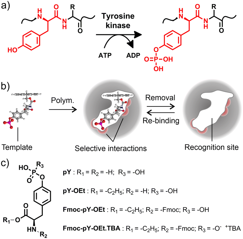 | ||
| Fig. 1 a) Phosphorylation of tyrosine (Y) by tyrosine kinase in the presence of adenosine triphosphate; b) principle of Fmoc-pY-OEt MIP cavity formation with selective interactions between the recognition site and the template; c) molecular structures of pY, pY-OEt, Fmoc-pY-OEt and Fmoc-pY-OEt.TBA. | ||
Alternatively, molecularly imprinted polymers (MIPs) are much more robust than antibodies, facilitating their use in denaturing solvents or more demanding conditions, such as high temperatures, wide pH range, or high ionic strength. A combination of complementary monomers in the pre-polymerisation mixture leads to MIPs exhibiting molecule-selective interactions. The polymerisation “freezes” the host–guest assembly, and forms binding “cavities” in the polymer network after template removal. The formed cavity comprises a specific recognition site, complementary to the template in size, shape, and molecular interaction demand, e.g., hydrogen bonding (Fig. 1b). Accordingly, MIPs for the enrichment of phosphorylated peptides have been reported, using structurally simpler templates such as phenylphosphonic acid16,17 or aromatic bisphosphonic acids18 as well as derivatives of pY19,20 or other phosphorylated amino acids21,22 for imprinting.
As reported in previous studies,23–27 MIP core–shell particles with indication functions can be useful tools for sensing and diagnostics, providing sensitive, reliable, and high-throughput analysis on a portable, miniaturised platform. Especially the incorporation of a few-nanometre thin MIP shell on the surface of a carrier bead allows for rapid analyte diffusion and, if a fluorophore is covalently integrated into the recognition matrix, yields an optical response upon analyte binding. In previous work we have shown that when addressing small organic molecules carrying terminal phosphonate groups, fluorescent crosslinkers which contain two binding sites that are arranged in a cleft-like fashion are advantageous as they exhibit high binding constants and provide a favourable signalling mode in solvents that do not interfere with hydrogen bonding interaction between host and guest.28,29 When used in conjunction with a liquid–liquid extraction step, the selective and sensitive detection of phosphorylated tyrosine becomes possible directly from aqueous samples. Such a system could be employed, for example, for the analysis of protein digestion products in clinical analysis and screening. It can equally be extended to the recognition of specific peptide sequences by imprinting target epitopes. When combined with microfluidic sample processing, which is known to offer several advantages for proteomics and biomarker discovery and detection,30–33 this approach has great diagnostic potential. An overview of recent MIP-based applications for amino acid, peptide and protein sensing is given in section V, ESI,† showing that microfluidic systems are lacking.
In this contribution, the bead-based ratiometric detection scheme of fluorescent probe crosslinker 1 (Fig. 2a) is transferred to a microfluidic chip format to demonstrate its applicability to rapid assays. Such a miniaturised device could yield an automated pY N-terminated peptide measurement system in the future. The tetrabutylammonium (TBA) salt of the fluorenylmethyloxycarbonyl (Fmoc) derivatised ethyl ester of phosphotyrosine (Fmoc-pY-OEt.TBA) (Fig. 1c) was considered as a good template for imprinting and implementation of a system for derivatisation, extraction, and detection of pY N-terminated amino-acid sequences.28 The Fmoc derivatisation of a peptide's N-terminus is a commonly employed method to increase sensitivity in peptide analysis.34,35 As an amide moiety has a low acidity compared to a carboxylic acid, imprinting the native pY into the polymer shell of the particles would not allow specific rebinding of amino acid sequences. The implementation of the Fmoc group also has the added benefit of aiding the transfer of the analyte from the aqueous sample-containing phase to the organic probe-containing phase by increasing the analyte's solubility in organic solvents. The setup was built by coupling a modular microfluidic system for amino acid derivatisation (Fmoc protection, ion exchange) to a multi-layered microfluidic chip for buffering, extraction (by micropillar-aided co-flow) and selective adsorption and detection using the MIP core–shell particles. A miniaturised optical assembly for low-light fluorescence measurements was developed and manufactured for the task. Requiring only miniaturised optoelectronic parts and optical fibres, the emission from the 1-containing MIP shell grafted from silica core particles upon addition of Fmoc-pY-OEt.TBA and pY N-terminated peptides could be monitored.
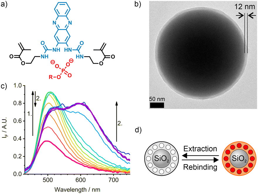 | ||
| Fig. 2 a) Indicator crosslinker 1 presenting two polymerisable linkers and the bis-urea cleft able to complex phosphate anions; b) TEM image of a SiO2/MIP core-shell sensory particle M1 with shell thickness of 12 nm; c) emission spectra of the MIP sensory particles, M1, in chloroform upon addition of Fmoc-pY-OEt.TBA; d) scheme of the extraction and rebinding of the template molecule into the MIP shell. | ||
Experimental
Materials
All chemicals and reagents were used as received from commercial providers. Water of Milli-Q quality was drawn from a Milli-Q ultrapure water purification system (Millipore Synthesis A10, Merck, Darmstadt) and used throughout the study. Solvents were filtered with 0.2 μm filters prior to injection into the microfluidic chips. PDMS/Teflon/glass microchips were manufactured as reported previously.36,37 Peptides pY-pep (H-pY-LSFTPPEK-Qtag; SPT-PTM-TQL-P03-01-pY) and Y-pep (H-Y-LSFTPPEK-Qtag; SPT-PTM-TQL-P03-00-pU) were purchased from JPT Peptide Technologies (Berlin) and used as received. Fmoc-pY-OEt.TBA and sensory particles M1 were prepared as outlined in our previous work.28,38Titration protocols
The fluorescence response of M1 on the macro-scale, upon biphasic extraction, was investigated by titration. Unless specified, to a suspension of particles in chloroform (2 mL, 0.5 g L−1) in a 10 mm quartz cell, water (1 mL) was added and the system was titrated with phosphorylated tyrosine tetrabutylammonium salt (Fmoc-pY-OEt.TBA, 1 mM in water) until saturation was reached. After each step of addition, the suspension was shaken for 1 min, the phases allowed to settle for 5 min before the fluorescence was measured under excitation at 405 nm. The spectra were then baseline-corrected to avoid experimental influences, particularly related to sedimentation of the particles.Generally, for the microfluidic assays, the particles were suspended in chloroform (0.4 g L−1). The analytes were diluted in chloroform or water in various concentrations from 0 to 200 μM. When specified additional solutions were also injected into the system: Fmoc-Cl solution (7.6 mM in acetone/acetonitrile 1/1; v/v), borate buffer (10 mM, pH 8) and tetrabutylammonium hydroxide (TBA-OH, 5 mM in water). After each change of sample, the system was left to equilibrate for 15 min before acquiring signal for 5 min. Errors were calculated according to propagation of the relative uncertainties along the successive steps of the assays.39,40
Miniaturised read-out system
The optical setup was built using standard opto-mechanic components. The excitation source was a 430 nm LED (LED 430-06, Roithner Lasertechnik, Vienna) filtered with a 450 nm short-pass filter (FESH0450, Thorlabs, Bergkirchen), divided with a 50/50 beam splitter (BS013, Thorlabs) and focussed through two optical fibres (200 μm core, M92L01, Thorlabs). The two ends of the fibres were held at angles of 35° above the PDMS/Teflon/glass chip and the excitation beams were directed on the chip's fluorescence chambers. Shutters were added to select between the fibres. Collection of the two fluorescent signals was also achieved with two optical fibres (200 μm core, M92L01, Thorlabs) at an angle of −15° above the chip both coupled and filtered with a 475 nm long-pass filter (GG475 Edmund Optics, Mainz) into an optical fibre bundle (7 × 200 μm core, BFL200HS02, Thorlabs). This bundle was connected to a miniature spectrometer (USB2000+, ILX-511B detector, Ocean Optics, Ostfildern), the signal acquisition was made computationally via the software Spectra Suite (Ocean Optics) with 5 s acquisition time per data point.The two fluorescence signals from the chambers at the beginning (S1) and the end (S2) of the chip were integrated for 5 min (approx. 60 points) over the wavelength ranges 470–580 nm (−1) and, only for S2, 580–750 nm (−2) which correspond to the two emission bands of the sensory particles, affording three signals of interest: S1-1, S2-1 and S2-2.
Results and discussion
Sensory particles M1
A sensory imprinted layer was grafted from the adequately functionalised surface of submicron-sized silica core particles via co-polymerisation of commercially available monomers and the indicator crosslinker 1 using Fmoc-pY-OEt.TBA as a template. The indicator 1 (Fig. 2a) that was obtained via a single-step condensation reaction from commercially available 2,3-diaminophenazine (2-DAP), can be conveniently excited in the blue-visible spectral range.28 The two amino groups of 2-DAP can be converted into a bis-urea cleft. Moreover, the intramolecular charge-transfer process from the NH groups in the 2,3-positions to the phenazine core does not involve rotational motions and the distal NH groups of the urea moieties can be equipped with polymerisable linkers. Polymerisation in the presence of the single deprotonated Fmoc-pY-OEt.TBA template anion with a TBA counter ion led to monodisperse particles with a thin polymer layer of 12 ± 8 nm (Fig. 2b). For later titration, the template removal was performed by successive washing with MeCN and CHCl3. Such method affords core–shell particles with stable molecularly imprinted cavities and could be reiterated after titrations to reuse the particles. Still, the low reagents consumption in the microfluidic scheme prevented us to recycle the particles in this study.Upon analyte binding in chloroform (Fig. 2c and d), occurring in 10–20 s,38 the absorption and emission maxima of M1 shift to higher wavelengths, with each sequential addition of analyte. This, along with an increase in intensity of the locally excited (LE) band at 501 nm indicates the formation of a hydrogen-bonded complex between the fluorescent crosslinker 1 and the analyte. After a certain concentration is reached, the LE band decreases with an accompanying development of an excited state proton transfer (ESPT) band at 633 nm. The absorption band does not change significantly during this second phase.28
The discrimination between the phosphorylated template, Fmoc-pY-OEt.TBA, and its non-phosphorylated counterpart (Fmoc-Y-OEt.TBA) for M1 particles is high (imprinting factor IF >3.5).28 A two-phase strategy was adopted to analyse aqueous samples. In this strategy, a MES-Tris buffer of pH 7.5 was placed on top of the organic phase, in which the M1 particles were suspended. An aqueous stock solution containing the target was added into the buffer phase. After equilibration, the fluorescence spectra of the suspended M1 particles in the bottom phase was recorded. Following this approach, a much higher selectivity was achieved (IF ≤15.9).28 The dramatic improvement is based on the selective protonation of the phenoxide groups of non-phosphorylated, deprotonated tyrosine in the buffered phase, whereas the phosphate remains anionic and can now be taken up exclusively by the binding pockets in the MIP shell.
Implementation of the miniaturised read-out system
The encouraging results obtained with the M1 particles in a standard test with a fluorometer prompted us to move to integration into a microfluidic device. Being able to efficiently perform these automated analyses directly at a point of care would significantly reduce analysis time and cost.Firstly, the compatibility of the M1 particles with a dedicated miniaturised optical read-out system was investigated. The design of the microfluidic chip consisted of a layer of PDMS, with and without carbon black doping, bonded on a glass substrate for mixing of sample and the particle suspension in chloroform.36 A Teflon layer was coated onto the PDMS walls to avoid adsorption of organic compounds and immobilisation of the particles.41 A passive mixer with a square serpentine channel (100 μm width, 400 μm period) ensured efficient mixing of the two solutions.37 Two larger channels, or chambers, of 1 mm width were used for fluorescence detection, incorporating a rhombus dispatcher to provide better flow dispersion across the width of the chamber. These chambers were added before and after mixing (Fig. 3).42 Two designs with respective lengths of 12 and 42 mm of the passive mixer were tested to also assess the reaction kinetics in the microfluidic volume scale.
 | ||
| Fig. 3 Design of the microfluidic channels for mixing of M1 particles (right bottom inlet) and Fmoc-pY-OEt.TBA (left bottom inlet) solutions in chloroform and fluorescence analyses before and after mixing. Zoomed-in areas show the square serpentine passive mixer and a 1 mm large fluorescence acquisition chamber (not to scale). | ||
Optical fibres were used for the optical readout of the setup to separate the opto-electronics from the fluidic part of the sensor (Fig. 4a–c). The opto-electronics could then be isolated in a water- and dust-proof case possibly with an electromagnetic shield to mitigate various risks and interferences.43 To ensure maximum fluorescence response and minimise coupling of the excitation beam into the emission beam, the excitation and emission fibres were held at angles of 35° and −15° respectively from the perpendicular direction above the chip (Fig. 4d and e). Each set of fibres was positioned on the chambers before and after mixing using XYZ micrometre stages.
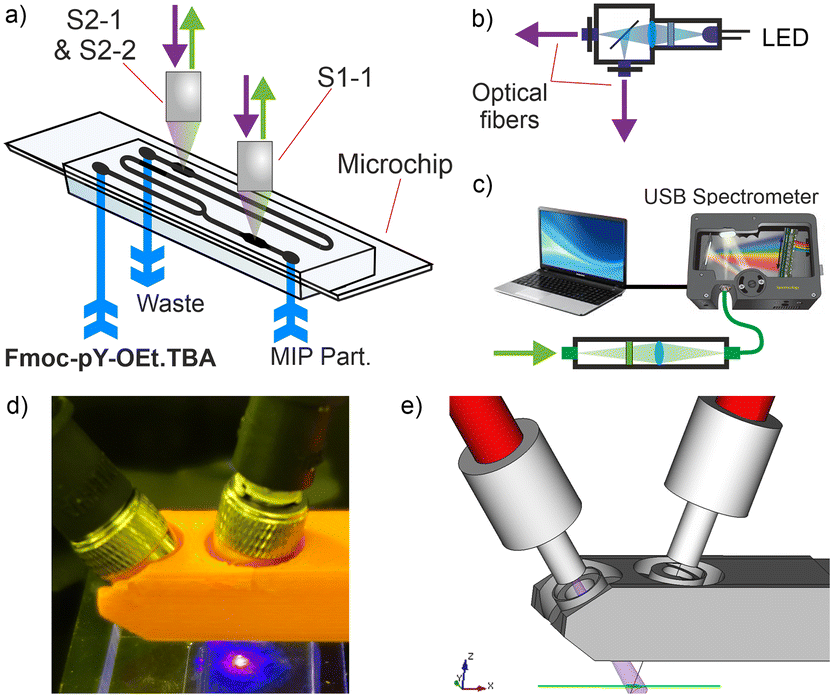 | ||
| Fig. 4 a) Double acquisition readout system to measure S1-1 and S2-1/S2-2 from the larger channels of the microfluidic platform; b) excitation source with LED beam coupled into two optical fibres via a 50/50 beam splitter; c) signal acquisition from an optical fibre bundle with filter and USB spectrometer; d) photograph and e) scheme of a 3D-printed fibres head above the microfluidic platform. | ||
Similar to the cuvette experiments, the presence of Fmoc-pY-OEt.TBA induced a fluorescence signal increase in the channel after mixing. Mostly the S2-1 signal (470–580 nm), corresponding to the LE emission, increased. Only at higher analyte concentrations is the single enhancement of S2-2 signal observed. It was observed that the 12 mm long passive mixer led to incomplete mixing compared to the longer version of 42 mm (Fig. 5a). The latter, however, induced significant back-pressure effects due to increased channel friction. At flow rates of 5 μL min−1 for both solutions, experimental mixing times of approximately 2.5 s (ttheo. = 2.5 s) and 10 s (ttheo. = 8 s) were measured for the 12 and 42 mm long passive mixers, respectively.
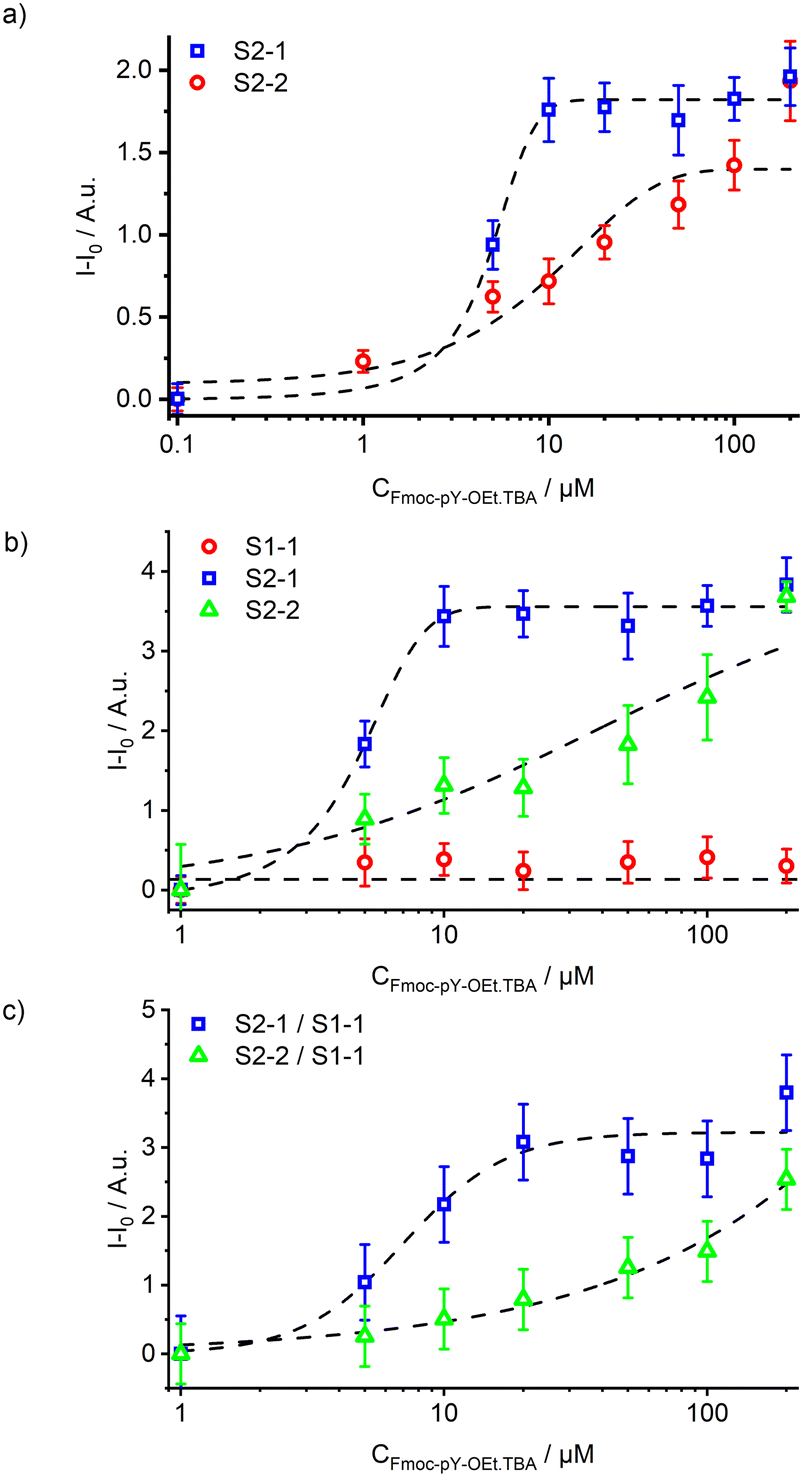 | ||
| Fig. 5 a) Signal S2-1 (470–580 nm) from the two microfluidic designs with 12 (red circles) and 42 (blue squares) mm long passive mixers upon increasing concentration of Fmoc-pY-OEt.TBA; b) response of the three acquisition channels S1-1 (red circles), S2-1 (blue squares) and S2-2 (green triangles) upon injection of increasing concentrations of Fmoc-pY-OEt.TBA in the monophasic microfluidic sensor; c) response of the sensor using S1-1 as internal reference. | ||
The combination of the microfluidic chip with the optical read-out system exhibited errors of 5 and 4% for transparent and black chips, respectively. Dynamic ranges of 1.5–10 μM and 10–50 μM were calculated for the signals S2-1 and S2-2 (Fig. 5b). Before the passive mixer, the fluorescence emission of the particles M1 remained stable indicating no analyte back-flow diffusion and negligibly small amounts of particles falling out of suspension. The initial M1 particle signal could be used as an on-chip reference. This, however, lead to ratiometric measurements with a propagated error of 16% corresponding to limit of detections of 5 and 10 μM of Fmoc-pY-OEt.TBA for S2-1 and S2-2 (Fig. 5c). Those elevated errors prevented us to perform ratiometric analyses for traces detection, but this reference could be used for higher concentrations of Fmoc-pY-OEt.TBA.
Micro-extractor implementation
To sense Fmoc-pY-OEt.TBA from aqueous media, the microfluidic system was then adapted to perform biphasic assays. This is necessary because the M1 sensory particles' behaviour is limited to organic solvents and incompatible with aqueous media in which the vast majority of peptide containing samples resides. Thus, an in-line extraction of the analyte of interest into the organic sensing phase is required. The enhanced properties of the M1 particles, in conjunction with the phase transfer agent TBA-OH, provides selective pre-concentration of the analyte, resulting in lower detection limits of phosphorylated biomarkers.To achieve this, a parallel flow extractor design was employed. Here, the chloroform suspended M1 particles are brought into contact alongside Fmoc-pY-OEt.TBA, dissolved in MES/Tris buffer (pH 7.5), where the two fluids run parallel to one another through the length of the extractor. During the contact time of these two flows, the analyte is transferred from the aqueous sample phase to the organic probe phase by liquid–liquid extraction. Running two phases parallel to one another for the whole length of a channel can be difficult to achieve. Thus, to stabilise the interface between phases, two techniques were tested, a three-dimensional guide design44 and a micropillar design.45 Incorporation of these features provides a good compromise between mass transfer efficiency and interfacial stability of the two immiscible flows. By incorporation of pillars or guides between the two phases, the resulting Laplace pressure helps to stabilise the interface of the two fluids, preventing flow instability caused by Kelvin–Helmholtz instabilities or momentary local pressure imbalances (Fig. S1†).46 Both chips were designed to maximise the contact time of two phases whilst maintaining an experimentally required length of interface between the two fluids, and parallel flow stability. From the cuvette experiments, the kinetic analysis showed that the phase transfer of Fmoc-pY-OEt.TBA occurs on the order of 30 s, in good agreement with observations made for similar analytes.38
From the two tested designs, the fluid interface in the microfluidic chips was better stabilised with vertical micropillars in between the two parallel channels (Fig. 6a), compared to insertion of a three-dimensional guide (ESI† section II, Fig. S2 and S3). The micro-extractor consists of two sets of parallel channels of 30 mm long, 100 μm width, and 25 μm depth separated by rhombus-shaped micropillars of 28 μm width. The reduction in channel depth was performed to accommodate the small micropillars. By reducing the channel depth, the resolution of the mould manufacturing process increases. Due to the smaller channel height and introduction of small features, the procedure for Teflon coating had to be adapted sightly from our previously reported methods, by reducing the concentration of Teflon solution in Fluorinert™ FC-70 from 1.0 to 0.5 wt%.36,37,41
 | ||
| Fig. 6 a) Micro-extractor design for Fmoc-pY-OEt.TBA extraction and detection with M1 sensory particles with micropillars as an interface stabiliser; b) response of the two acquisition channels S2-1 (blue squares) and S2-2 (red circles) upon injection of increasing concentrations of Fmoc-pY-OEt.TBA in the aqueous phase and extraction and detection by the M1 particles in the pillar geometry extractor. | ||
In the micro-extractor, stability was maintained up to a flow rate of 35 μL min−1 for the chloroform phase, which is 1.7 times higher than the water flow (Fig. S4†). This micro-extractor geometry allowed a broader range of flow combinations compared to the guide geometry and thus provided a more robust solution for liquid–liquid extraction on chip. This increased range of flow combinations can be attributed to the significantly larger stabilising Laplace pressure achieved by both the micropillars and the reduction in channel height (Fig. S1†). The guide design stabilises the interface by reducing the contact area of the two fluids, however, the interface still extends over the entire length of the channel. In the micropillar extractor, the interface of the two fluids is separated by the individual pillars. This compartmentalisation of the interface significantly increases the stabilising potential of the design. The reduction in channel height also intrinsically stabilises the liquid–liquid interface. According to the flow mapping of this design (Fig. S4†), the organic and aqueous flow rates were set at the minimum stable flow rates of 7.5 and 5 μL min−1, respectively, to ensure the longest possible extraction time of approximately 2.5 s.
After the micro-extractor, both microchannels containing chloroform and water were widened to a channel depth of 100 μm to collect more fluorescence signal in the designated area. For this, a two-layer lithography process for the mould manufacturing was followed, starting with a 25 μm layer for the extractor part and continuing with a 75 μm layer for the fluorescence chamber.47 The importance of the output channels' back pressure equilibrium appeared to be significant for the stability of the micro-extractor. The water phase outlet channel had to be also adapted to present comparable friction loss to the chloroform output channel, thus stabilising the interface.48
Combining this microfluidic design with the previously described read-out system allowed the detection of Fmoc-pY-OEt.TBA at concentrations of 5–20 μM using both S2-1 and S2-2 with analyses errors of 4–10% (Fig. 6b).
In-line derivatisation and ion exchange
In addition to the microchip for Fmoc-pY-OEt.TBA extraction and detection with M1 sensory particles, the implementation of an in-line derivatisation of pY with Fmoc-Cl (fluorenylmethyloxycarbonyl chloride) into a modular microfluidic system was investigated (Fig. 7a). The Fmoc derivatisation is a common method to improve the sensitivity of liquid chromatography analyses by increasing the absorption coefficient,49 and it appeared that its presence enhances the selectivity of M1 by assisting with the phase transfer of the analyte. Most reported derivatisation protocols are related to batch reaction in vials prior to the analysis.50 Therefore it seemed interesting for us to design a system to perform this step directly prior to detection on chip. It consisted of a combination of a modular tube-based reaction unit for analyte derivatisation with Fmoc-Cl and a soft lithography-based chip for the excess reagent removal.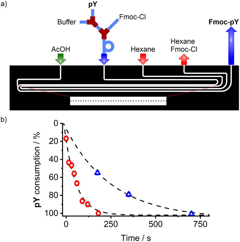 | ||
| Fig. 7 a) Scheme of the design of the hybrid derivatisation unit for pY reaction with Fmoc-Cl (tubing) and purification (PDMS/glass micro-extractor with micropillars as interface stabiliser); b) pY consumption upon conversion into Fmoc-pY in a stirred vial (red circles) and in the microfluidic assembly (blue triangles). | ||
In the tubing, pY (40 μM, water, 0.8 μL min−1) was diluted in borate buffer (1 mM, pH 8, 0.2 μL min−1) before mixing with Fmoc-Cl (7.5 mM, acetone/acetonitrile; 1/1 v/v solution, 1 μL min−1). The tube approach was chosen for this part so that the length of the reaction loop could be easily adapted to ensure quantitative derivatisation of the analyte's amine moiety. The second part of the system was identical to the micro-extractor with micropillars described above. In this extractor, the excess of Fmoc-Cl reagent is extracted with hexane, quenching the derivatisation reaction, and preventing any non-specific binding of excess Fmoc-Cl to the MIP particles in the organic phase. The possible flow combinations for water/hexane extraction were broader than those found for water/chloroform (Fig. S5†) which can be attributed to the interfacial tension51 between water and hexane (50.4 mN m−1)52 being greater than that of water and chloroform (32.8 mN m−1).53
The stability was maintained for a water/hexane flow ratio of 1![[thin space (1/6-em)]](https://www.rsc.org/images/entities/char_2009.gif) :3 as an empirical law, and aqueous flows of up to 10 μL min−1. The buffered aqueous phase containing Fmoc-pY can be then acidified with acetic acid (50 mM) to obtain the neutral analyte. To validate the derivatisation conversion, the acidified phase containing Fmoc-pY was spotted on a TLC plate (eluent: iPrOH/H2O 1/1 v/v, RfpY = 0.55) to monitor pY complete consumption (Fig. 7b), made visible by treating the plate with potassium permanganate. A reaction time of 12 min was found to be necessary before extracting the excess of Fmoc-Cl and injecting the derivatised analyte into the detection segment of the chip. For ultrafast analysis, such derivatisation could be accelerated by heating up the system with a Peltier module.54
:3 as an empirical law, and aqueous flows of up to 10 μL min−1. The buffered aqueous phase containing Fmoc-pY can be then acidified with acetic acid (50 mM) to obtain the neutral analyte. To validate the derivatisation conversion, the acidified phase containing Fmoc-pY was spotted on a TLC plate (eluent: iPrOH/H2O 1/1 v/v, RfpY = 0.55) to monitor pY complete consumption (Fig. 7b), made visible by treating the plate with potassium permanganate. A reaction time of 12 min was found to be necessary before extracting the excess of Fmoc-Cl and injecting the derivatised analyte into the detection segment of the chip. For ultrafast analysis, such derivatisation could be accelerated by heating up the system with a Peltier module.54
For the detection of the aqueous analyte, to favour the phase transfer of amino acids into the organic phase, a quaternary ammonium cation, TBA, was added to react with the phosphate site and form a lipophilic ion pair. Such step was performed prior to analysis of the template Fmoc-pY-OEt.TBA. As shown in the ESI† (Fig. S6 and S7), the ammonium cation could be introduced in excess either as hydroxide salt in the aqueous phase or as perchlorate salt in the organic phase. The hydroxide salt was opted for due to its more consistent phase transfer behaviour as well as the formation of water rather than insoluble precipitates. The response of the M1 particles upon addition of Fmoc-pY-OEt showed similar trends, therefore TBA-OH was introduced in excess (5 mM) together with the borate buffer in the tube/chip unit to allow a longer ion exchange time in parallel to the derivatisation.55,56
Analysis of peptides
The combined platform for the derivatisation and counter ion exchange of pY N-terminated peptides, followed by extraction and detection with sensory particles M1 was implemented. Two reference materials for MS analyses (Scheme 1) were used for validation of the platform: pY-pep (H-pY-LSFTPPEK-Qtag) and Y-pep (H-Y-LSFTPPEK-Qtag). | ||
| Scheme 1 Molecular structure of the peptides Y-pep and pY-pep before and after derivatisation and counter ion exchange (Qtag = C17H21N5O8 (m/z 423.13901), patented formula from JPT Peptide Technologies). | ||
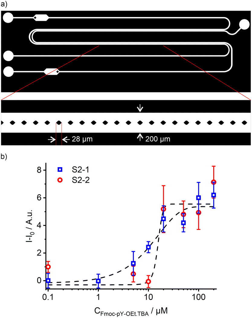
As described before, the protection of the free amino group of the peptide and the counter ion exchange occurred in the tubing section before the resulting mixture was injected into the PDMS/Teflon/glass microchip. In the microchip, a first 30 mm long micro-extractor with micropillars is used for excess Fmoc-Cl removal by phase transfer into hexane (Fig. 8a). The water phase containing Fmoc-pY-pep.TBA or Fmoc-Y-pep is then injected into a second pillar micro-extractor of 2 × 30 mm. The presence of TBA counter ion as a phase transfer agent helps to transfer some of the analyte into the chloroform phase by forming an ion pair.57 Finally, the M1 sensory particles can bind selectively Fmoc-pY-pep.TBA for which they present the best affinity and convert the binding event into a fluorescence response acquired by the miniaturised read-out system from an enlarged 1 mm channel. Both micro-extractors with pillars exhibited stability towards water, hexane and chloroform flow rates which were comparable to the previously tested single units. The mapping of water/hexane flow rates vs. stability of the first micro-extractor showed two stable regimes (Fig. S8a†). For flows up to 2 μL min−1 of water, the hexane flow rates should be 7 times higher, but for higher values, the hexane flow rates should be equal to (2 × Qwater + 10) μL min−1. In the second micro-extractor, stability was maintained for chloroform flows 1.9 times higher than the water flows, up to a flow rate of 12 μL min−1 for the chloroform phase (Fig. S8b†). According to this mapping, flows of aqueous, hexane and chloroform phases were set at 2, 10 and 4 μL min−1 respectively (water flow: analyte: 0.8 μL min−1; buffer/TBA-OH: 0.2 μL min−1; Fmoc-Cl: 1 μL min−1), to ensure extraction times of approximately 2.5 s for Fmoc-Cl excess removal and 5 s for the analyte.
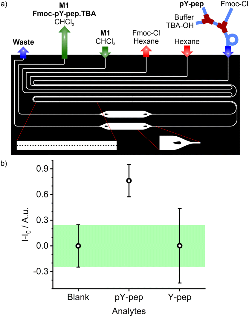 | ||
| Fig. 8 a) Scheme of the chip design for pY-pep derivatisation, purification, extraction, and detection; b) signal intensity measured upon injection of blank solution (water) or pY-pep and Y-pep solutions in the microfluidic assay platform. | ||
Combining this microfluidic platform with the read-out system showed that the fluidic system allowed the detection and differentiation of Fmoc-pY-pep.TBAvs.Fmoc-Y-pep.TBA at concentrations of 25 μM (Fig. 8b). The total analysis time was 20 min per sample and negligible memory effects were observed allowing successive sample analysis without intensive rinsing of the system. Equivalent macro-assays did not allow detection of pY-pep due to higher uncertainties (Fig. S9†). Indeed, microfluidics allowed better control on the volumes (flow rates), reaction times and extraction times which are crucial for low uncertainty measurements in such multiple steps assays. Finally, the reusability of the present chips is mainly limited by clogging with the particles upon strenuous use as well as slight swelling of the channels with organic solvent use because of slight imperfections in the coating. Both problems however are engineering issues which could be dealt with when transferring from a lab prototype to a commercial product.
Conclusions
In conclusion, we have demonstrated the feasibility of incorporating sensory particles coated with a fluorescent molecularly imprinted polymer layer that responds selectively to pY N-terminated peptides into a microfluidic sensor and its application for the detection of aqueous phosphorylated tyrosine. This sensor is a combination of a hybrid tube/chip unit for derivatisation of the amino acid's N-terminus with Fmoc-Cl, ion exchange and a PDMS/Teflon/glass microchip integrating a micro-extractor for analyte purification, extraction, and detection. The particles are excited with an LED coupled into an optical fibre, and the emitted fluorescence is measured with a USB spectrometer also via an optical fibre. The read-out system had been optimised for best sensitivity with Fmoc-pY-OEt before testing two types of micro-extractors with different flow stabilising techniques, guides or micropillars. The micropillar geometry presented the best performance with the highest range of flow stability and the best extraction efficiency, giving a dynamic range of 1.5–50 μM. The microfluidic platform for derivatisation, extraction and detection was finally implemented and allowed the differentiation between pY and Y N-terminated peptides. Further optimisation of the efficiency and processing of the various steps for improved peptide analysis is currently performed in our laboratory. We envision that when coupled for instance with mass spectrometric analysis such a fluorescence-signalled peptide enrichment can yield superior performance as compared to conventional SPE column pre-concentration, especially when realised in an in-flow manner as a miniaturised pre-sorting and pre-concentrating module for proteomics. Such an approach would also significantly enhance the applicability of molecularly imprinted polymers in bioanalytical and diagnostic workflows.Author contributions
S. C. Burnage: investigation, writing – original draft – review & editing. J. Bell: investigation, supervision, validation, writing – original draft – review & editing. W. Wan: investigation, writing – review & editing. E. Kislenko: investigation, writing – review & editing. K. Rurack: funding acquisition, supervision, writing – review & editing.Conflicts of interest
There are no conflicts to declare.Acknowledgements
This work has received funding from the European Union's Horizon 2020 research and innovation programme under the Marie Skłodowska-Curie grant agreement No 722171 (BioCapture). S. B. and E. K. are grateful to K. Gawlitza of BAM's Chemical and Optical Sensing Division for supervision.References
- W.H.O., Systematic review of needs for medical devices for ageing populations, 2015, https://www.who.int/publications/i/item/9789241509220, (accessed 01/2023) Search PubMed.
- W.H.O., Cancer, 2022, https://www.who.int/news-room/fact-sheets/detail/cancer, (accessed 01/2023) Search PubMed.
- B. W. Stewart, F. Bray, D. Forman, H. Ohgaki, K. Straif, A. Ullrich and C. P. Wild, Carcinogenesis, 2016, 37, 2–9 CrossRef CAS PubMed.
- N. Karachaliou, C. Mayo-de-Las-Casas, M. A. Molina-Vila and R. Rosell, Ann. Transl. Med., 2015, 3, 36 Search PubMed.
- J. A. Ubersax and J. E. Ferrell Jr, Nat. Rev. Mol. Cell Biol., 2007, 8, 530–541 CrossRef CAS PubMed.
- K. Y. Kim, K. Y. Shin and K.-A. Chang, Biomolecules, 2021, 11, 980 CrossRef CAS PubMed.
- N. Cavallarin, M. Vicario and A. Negro, CNS Neurol. Disord.: Drug Targets, 2010, 9, 471–481 CrossRef CAS PubMed.
- V. Singh, M. Ram, R. Kumar, R. Prasad, B. K. Roy and K. K. Singh, Protein J., 2017, 36, 1–6 CrossRef CAS PubMed.
- E. T. McKinley, H. Liu, W. H. McDonald, W. Luo, P. Zhao, R. J. Coffey, S. K. Hanks and H. C. Manning, PLoS One, 2013, 8, e80207 CrossRef CAS PubMed.
- T. Bilbrough, E. Piemontese and O. Seitz, Chem. Soc. Rev., 2022, 51, 5691–5730 RSC.
- A. Kalyuzhnyy, P. A. Eyers, C. E. Eyers, E. Bowler-Barnett, M. J. Martin, Z. Sun, E. W. Deutsch and A. R. Jones, J. Proteome Res., 2022, 21(6), 1510–1524 CrossRef CAS PubMed.
- Y. Bian, L. Li, M. Dong, X. Liu, T. Kaneko, K. Cheng, H. Liu, C. Voss, X. Cao, Y. Wang, D. Litchfield, M. Ye, S. S. C. Li and H. Zou, Nat. Chem. Biol., 2016, 12, 959–966 CrossRef CAS PubMed.
- J. Rush, A. Moritz, K. A. Lee, A. Guo, V. L. Goss, E. J. Spek, H. Zhang, X.-M. Zha, R. D. Polakiewicz and M. J. Comb, Nat. Biotechnol., 2005, 23, 94–101 CrossRef CAS PubMed.
- J. Lin, Z. Xie, H. Zhu and J. Qian, Briefings Funct. Genomics, 2010, 9, 32–42 CrossRef CAS PubMed.
- L. J. Wilson, A. Linley, D. E. Hammond, F. E. Hood, J. M. Coulson, D. J. MacEwan, S. J. Ross, J. R. Slupsky, P. D. Smith, P. A. Eyers and I. A. Prior, Cancer Res., 2018, 78, 15–29 CrossRef CAS PubMed.
- L. Xu, Y. Hu, F. Shen, Q. Li and X. Ren, J. Chromatogr. A, 2013, 1293, 85–91 CrossRef CAS PubMed.
- X. Yang and Y. Xia, J. Sep. Sci., 2016, 39, 419–426 CrossRef CAS PubMed.
- J. Zhao, H. He, Z. Guo and Z. Liu, Anal. Chem., 2021, 93, 16194–16202 CrossRef CAS PubMed.
- M. Emgenbroich, C. Borrelli, S. Shinde, I. Lazraq, F. Vilela, A. J. Hall, J. Oxelbark, E. De Lorenzi, J. Courtois, A. Simanova, J. Verhage, K. Irgum, K. Karim and B. Sellergren, Chem. – Eur. J., 2008, 14, 9516–9529 CrossRef CAS PubMed.
- M. Duarte, P. Subedi, E. Yilmaz, K. Marcus, T. Laurell and S. Ekstrom, J. Mol. Recognit., 2018, 31, e2677 CrossRef PubMed.
- M. Liu, T. M. Tran, A. A. A. Elhaj, S. B. Torsetnes, O. N. Jensen, B. Sellergren and K. Irgum, Anal. Chem., 2017, 89, 9491–9501 CrossRef CAS PubMed.
- A. Incel, I. A. Diez, C. Wierzbicka, K. Gajoch, O. N. Jensen and B. Sellergren, Anal. Chem., 2021, 93, 3857–3866 CrossRef CAS PubMed.
- S. Wagner, J. Bell, M. Biyikal, K. Gawlitza and K. Rurack, Biosens. Bioelectron., 2018, 99, 244–250 CrossRef CAS PubMed.
- W. Li, X. Zhang, T. Li, Y. Ji and R. Li, Anal. Chim. Acta, 2021, 1148, 238196 CrossRef CAS PubMed.
- P. Sawetwong, S. Chairam, P. Jarujamrus and M. Amatatongchai, Talanta, 2021, 225, 122077 CrossRef CAS PubMed.
- X. L. Hu, Y. Guo, J. N. Zhang, X. H. Wang, G. Z. Fang and S. A. Wang, Chem. Eng. J., 2022, 433, 134499 CrossRef CAS.
- A. D. Cabral, T. B. Radu, E. D. de Araujo and P. T. Gunning, RSC Chem. Biol., 2021, 2, 815–829 RSC.
- W. Wan, A. B. Descalzo, S. Shinde, H. Weisshoff, G. Orellana, B. Sellergren and K. Rurack, Chem. – Eur. J., 2017, 23, 15974–15983 CrossRef CAS PubMed.
- M. Kimani, E. Kislenko, K. Gawlitza and K. Rurack, Sci. Rep., 2022, 12, 14151 CrossRef CAS PubMed.
- N. Sitkov, T. Zimina, A. Kolobov, V. Karasev, A. Romanov, V. Luchinin and D. Kaplun, Micromachines, 2021, 12, 691 CrossRef PubMed.
- R. Vitorino, S. Guedes, J. Pinto da Costa and V. Kašička, Nanomaterials, 2021, 11, 1118 CrossRef CAS PubMed.
- E. Weaver, S. Uddin, D. K. Cole, A. Hooker and D. A. Lamprou, Appl. Sci., 2021, 11, 4109 CrossRef CAS.
- L.-Y. Hung, H.-W. Wu, K. Hsieh and G.-B. Lee, Microfluid. Nanofluid., 2014, 16, 941–963 CrossRef CAS.
- K. Gartenmann and S. Kochhar, J. Agric. Food Chem., 1999, 47, 5068–5071 CrossRef CAS PubMed.
- P. Uutela, R. A. Ketola, P. Piepponen and R. Kostiainen, Anal. Chim. Acta, 2009, 633, 223–231 CrossRef CAS PubMed.
- P. Ashokkumar, J. Bell, M. Buurman and K. Rurack, Sens. Actuators, B, 2018, 256, 609–615 CrossRef CAS.
- A. Tillo, J. Bartelmess, V. P. Chauhan, J. Bell and K. Rurack, Anal. Chem., 2019, 91, 12980–12987 CrossRef CAS PubMed.
- W. Wan, M. Biyikal, R. Wagner, B. Sellergren and K. Rurack, Angew. Chem., Int. Ed., 2013, 52, 7023–7027 CrossRef CAS PubMed.
- K. Rurack and M. Spieles, Anal. Chem., 2011, 83, 1232–1242 CrossRef CAS PubMed.
- J. Bell, E. Climent, M. Hecht, M. Buurman and K. Rurack, ACS Sens., 2016, 1, 334–338 CrossRef CAS.
- V. Arima, M. Bianco, A. Zacheo, A. Zizzari, E. Perrone, L. Marra and R. Rinaldi, Thin Solid Films, 2012, 520, 2293–2300 CrossRef CAS.
- N. A. Abdelshafi, J. Bell, K. Rurack and R. J. Schneider, Drug Test. Anal., 2019, 11, 492–500 CrossRef CAS PubMed.
- S. Sankaran, K. Deshmukh, M. B. Ahamed and S. K. Khadheer Pasha, Composites, Part A, 2018, 114, 49–71 CrossRef CAS.
- M. Tokeshi, T. Minagawa, K. Uchiyama, A. Hibara, K. Sato, H. Hisamoto and T. Kitamori, Anal. Chem., 2002, 74, 1565–1571 CrossRef CAS PubMed.
- J. Berthier, V.-M. Tran, F. Mittler and N. Sarrut, Sens. Actuators, A, 2009, 149, 56–64 CrossRef CAS.
- C. Xu and T. Xie, Ind. Eng. Chem. Res., 2017, 56, 7593–7622 CrossRef CAS.
- L. Zhao, T. Wu, J. P. Lefevre, I. Leray and J. A. Delaire, Lab Chip, 2009, 9, 2818–2823 RSC.
- C. F. Soon, Y. H. Yin, K. S. Tee, M. K. Ahmad, M. Z. Sahdan and N. Nayan, IOP Conf. Ser.: Mater. Sci. Eng., 2016, 160, 012086 Search PubMed.
- Automatic precolumn derivatization for the HPLC determination of aliphatic amines in air, Application Note 1012, https://assets.thermofisher.com/TFS-Assets/CMD/Application-Notes/AN-1012-LC-Aliphatic-Amines-Air-AN70115-EN.pdf, (accessed 01/2023).
- S. Einarsson, S. Folestad, B. Josefsson and S. Lagerkvist, Anal. Chem., 1986, 58, 1638–1643 CrossRef CAS.
- I. Barmak, A. Gelfgat, H. Vitoshkin, A. Ullmann and N. Brauner, Phys. Fluids, 2016, 28, 044101 CrossRef.
- S. Zeppieri, J. Rodríguez and A. L. López de Ramos, J. Chem. Eng. Data, 2001, 46, 1086–1088 CrossRef CAS.
- M. Bumbac, C. M. Nicolescu, B. C. Serban, O. Buiu, M. Olteanu and R. L. Olteanu, J. Sci. Arts, 2018, 43, 459–470 Search PubMed.
- S. Vo Duy, G. Munoz, Q. T. Dinh, D. Tien Do, D. F. Simon and S. Sauvé, PLoS One, 2019, 14, e0220698 CrossRef CAS PubMed.
- M. O. González-Mares, M. G. García-Jiménez and L. M. De León Rodríguez, ECS Trans., 2008, 15, 353–363 CrossRef.
- S. V. Campos, L. P. Miranda and M. Meldal, J. Chem. Soc., Perkin Trans. 1, 2002, 682–686 RSC.
- S. Wagner, C. Zapata, W. Wan, K. Gawlitza, M. Weber and K. Rurack, Langmuir, 2018, 34, 6963–6975 CrossRef CAS PubMed.
Footnotes |
| † Electronic supplementary information (ESI) available: Synthesis of sensory particles M1, micro-extractor parameters and designs, in-line derivatisation and ion exchange, analysis of peptides. See DOI: https://doi.org/10.1039/d2lc00955b |
| ‡ Present address: Surflay Nanotec GmbH, Max-Planck-Straße 3, 12489 Berlin, Germany. |
| This journal is © The Royal Society of Chemistry 2023 |