
 Open Access Article
 This Open Access Article is licensed under a Creative Commons Attribution-Non Commercial 3.0 Unported Licence
Multiplexed analysis of signalling proteins at the single-immune cell level†
Claudius L.
Dietsche
 ,
Elisabeth
Hirth
and
Petra S.
Dittrich
*
,
Elisabeth
Hirth
and
Petra S.
Dittrich
*
Department of Biosystems and Engineering, ETH Zurich, Mattenstrasse 26, 4125 Basel, Switzerland. E-mail: petra.dittrich@bsse.ethz.ch
First published on 15th December 2022
Abstract
High numbers of tumour-associated macrophages (TAMs) in the tumour microenvironment are associated with a poor prognosis. However, the effect of TAMs on tumour progression depends on the proteins secreted by individual TAMs. Here, we developed a microfluidic platform to quantitatively measure the secreted proteins of individual macrophages as well as macrophages polarized by the culture medium derived from breast cancer cells. The macrophages were captured in hydrodynamic traps and isolated with pneumatically activated valves for single-cell analysis. Barcoded and functionalized magnetic beads were captured in specially designed traps to determine the secreted proteins by immunoassay. Individual bead trapping facilitated the recording of the protein concentration since all beads were geometrically constrained in the same focal plane, which is an important requirement for rapid and automated image analysis. By determining three signaling proteins, namely interleuking 10 (IL-10), vascular endothelial growth factor (VEGF), and tumour necrosis factor alpha (TNF-α), we successfully distinguished between differently polarized macrophages. The results indicate a heterogeneous pattern, with M2 macrophages characterized by a higher secretion of IL-10, while M1 macrophages secrete high levels of the inflammatory cytokine TNF-α. The macrophages treated with the supernatant from cancer cells show a similar signalling pattern to M2 macrophages with an increased secretion of the pro-tumoural cytokine VEGF. This microfluidic method resolves correlations in signaling protein expression at the single-cell level. Ultimately, single-macrophage analysis can contribute to the development of novel therapies aimed at reversing M2-like TAMs into M1-like TAMs.
Introduction
Cytokine signalling is an important process for cell-to-cell communication, enabling complex interactions between cells in a highly heterogeneous population.1,2 However, cell-to-cell signalling not only plays a critical role in the development, survival, and proliferation of its own population but also has a profound impact on the surrounding microenvironment.3 Tissue-resident macrophages are immune cells that reside throughout the body and influence the course of diseases based on cell-to-cell signaling.4 Of particular interest are the effects of macrophages on the tumour microenvironment (TME), as they can account for up to 50% of tumour mass and are important regulators of cell proliferation and the apoptosis cycle.2,5,6 Several studies have shown that tumour-associated macrophages (TAMs) have the potential to affect tumour growth in a positive as well as negative way depending on the dominating phenotype.7–9 Macrophages are highly plastic and within the TME can change their phenotype, a process known as polarization, in response to stimuli such as interferon gamma (INF-γ), interleukin 4 (IL-4) and interleukin 13 (IL-13).10,11 Polarized macrophages can be classified as classically activated (M1) macrophages and alternatively activated (M2) macrophages. The polarization of macrophages can be determined by the combination of cytokines that each individual macrophage produces and secretes. Tumour necrosis factor alpha (TNF-α) is associated with tumour suppressive properties, whereas interleukin 10 (IL-10) and vascular endothelial growth factor (VEGF) are associated with tumour proliferation.12,13 Novel treatment approaches focus on the repolarization of tumour-promoting (M2-like) macrophages to tumour-suppressing (M1-like) macrophages.14–17 Therefore, due to the heterogeneity of the TME and TAMs in particular, it is critical to deepen the understanding of the underlying mechanisms at the single-cell level to eventually find an effective and reliable treatment.In microfluidic systems, fluids are confined and manipulated in sub-millimetre structures, making them ideal for studying protein secretion at the single-cell level. The dimensions of these engineered systems are in the low micrometre range (i.e., the same order of magnitude as living cells), allowing precise and rapid manipulation of biological samples.18–22 The capture and isolation of single cells at this microscale has enabled the development of high-throughput single-cell analysis techniques in recent years. In particular, single-cell RNAseq has attracted considerable interest due to its sensitivity, throughput, and multiplexing capabilities.23 Knowledge of the cell's transcriptome provides an extensive insight into the up- and downregulation of gene expression but cannot reflect the cell state at the protein level, e.g., RNAseq is not suitable for assessing the secretion of proteins.
Droplet microfluidics is particularly well suited for high-throughput single-cell analysis due to the compartmentalization of single cells in droplets.23–27 However, droplet microfluidics is hampered by the inability to replace reagents which can affect the detection of secreted proteins with high sensitivity. Alternatively, open nano wells have been utilized for the purpose of highly sensitive detection of single-cell secreted proteins.38,39 The shortcoming with this technology is that the secreted proteins are not contained in the well but can diffuse out of them.38 In contrast, microchambers have been developed for isolation of single cells with the flexibility of conventional 96-well plates.28,29 Due to their flexibility in reagent exchange, the sensitivity of microchamber bioassays far exceeds that of droplet microfluidics. Precisely positioned and designed mechanical columns, known as hydrodynamic traps, within the microchambers enable efficient and label-free immobilization and isolation of single cells.22 Due to their micrometre scale, microfluidic systems allow high parallelization of the microchambers and simultaneous readout of hundreds to thousands of individual cells.21
Immunoassays allow quantification of proteins on the cell membrane or those secreted by the cell. Multiplexed quantification of proteins in single cells has been achieved by coating different sections of a microchamber with different antibodies.30–32 This method requires immobilization of capture antibodies during microfluidic device fabrication, which increases the fabrication complexity. In addition, this fabrication method results in high background noise due to nonspecific binding of antibodies during the fabrication process. Recently, in Armbrecht et al., we presented a new method in which multiplexed quantification of intracellular proteins was enabled by introducing barcoded magnetic beads with specifically coated antibodies.28 Due to commercially available beads with more than 300 target proteins, this method can be easily adapted to proteins of interest and has a higher sensitivity compared to previous methods. However, in our previous approach, the cells were captured in the same traps as the magnetic beads, which necessitated cell tagging. Furthermore, the relatively large magnetic traps led to bead aggregation and overlap, which caused signal diminution and difficulties in automation.
In this work we have significantly improved the microfluidic platform for the quantitative measurement of secreted proteins at the single-cell level. We use hydrodynamic traps to capture single cells by size without tags (i.e., without the need of attaching beads to the cells) and magnetic traps to immobilize barcoded, functionalized magnetic beads in the same microchambers. The magnetic traps are implemented using small cavities enforcing single-bead occupancy at a specific location in the chamber. This design greatly improves automated imaging and image analysis, which is a prerequisite for a further increase in throughput. Based on an on-bead immunoassay, the secretion profile of differentially polarized macrophages is investigated and analysed.
Experimental
Wafer fabrication
The silicon master moulds for the PDMS microfluidic chip were fabricated using soft lithography. One layer was required for the cell suspension and analysis (fluid layer), and a second layer was required for defining the valves (pressure layer). Each layer required a mould, prepared by optical lithography. Briefly, a thin layer of negative photoresist (SU8 from micro resist technology, Germany) was spun onto a 100 mm silicon wafer. The speed of the spin coating determined the height of the photoresist. After a bake prior to exposure, SU8 was exposed in a specific pattern to allow crosslinking of SU8 at the exposed areas. The pattern was defined by a high-resolution mask previously designed in CAD software and printed by Selba S.A. (Switzerland). The mould for the fluid layer with the hydrodynamic and magnetic traps was a SU8 wafer comprising two heights. The first layer consists of the fluid layer containing the hydrodynamic traps and SU8 3025 was spin-coated at 3000 rpm to a height of 25 μm. After exposure and post-exposure bake, a second layer of SU8 3010 was spin-coated onto the liquid layer at 4000 rpm (∼8 μm). After exposure and post-exposure bake, SU8 was developed in an mr-Dev 600 developer for 5 minutes. The same procedure was used for the preparation of the master mould for the pressure layer. However, it was spun with SU8 3010 at a speed of 1500 rpm to achieve a final height of 15 μm. The developing time was reduced to 3 minutes. The features on the pressure wafer were designed 1.6% smaller than the fluid layer to account for the shrinking of PDMS during the curing procedure.Device fabrication
PDMS was prepared by mixing the oligomer and the crosslinking agent (Sylgard 184 silicone elastomer kit, Dow) in a 10![[thin space (1/6-em)]](https://www.rsc.org/images/entities/char_2009.gif) :1 ratio. After thoroughly mixing the solution, it was degassed in a vacuum chamber for 15 minutes. The PDMS was poured onto the moulds and cured at 80 °C for a specified time as indicated below. For the fluid layer, 35 g of PDMS was poured onto the wafer to reach a height of about 4 mm. PDMS was then cured for 1.5 hours. The two inlets of the fluid layer were punched with a biopsy punch and the device was cut into the final shape of 4 × 2 cm with a scalpel. For the pressure layer, 5 g of PDMS was spun onto the second wafer at 2500 rpm. This resulted in a PDMS layer height of approximately 35 μm. The wafer was then cured for 30 minutes. A plain wafer was used to spin coat a thin layer of crosslinking agent at 6000 rpm. The cured and cut-out fluid devices were dipped into the thin layer of crosslinking agent. A microscope was used to align the fluid device on the pressure layer. After alignment, the fluid device was surrounded by PDMS on the pressure layer to seal it completely. After curing for another 1.5 hours, the device was cut into the desired shape with a scalpel and the four valve inlets of the pressure layer were punched out with a biopsy puncher. The finished devices were then bonded to a microscope slide #3. To prepare for this, the device and slide were cleaned with IPA and a tape, and placed in a plasma oven for 30 seconds. After bonding, the finished device was heated to 100 °C for 15 minutes.
:1 ratio. After thoroughly mixing the solution, it was degassed in a vacuum chamber for 15 minutes. The PDMS was poured onto the moulds and cured at 80 °C for a specified time as indicated below. For the fluid layer, 35 g of PDMS was poured onto the wafer to reach a height of about 4 mm. PDMS was then cured for 1.5 hours. The two inlets of the fluid layer were punched with a biopsy punch and the device was cut into the final shape of 4 × 2 cm with a scalpel. For the pressure layer, 5 g of PDMS was spun onto the second wafer at 2500 rpm. This resulted in a PDMS layer height of approximately 35 μm. The wafer was then cured for 30 minutes. A plain wafer was used to spin coat a thin layer of crosslinking agent at 6000 rpm. The cured and cut-out fluid devices were dipped into the thin layer of crosslinking agent. A microscope was used to align the fluid device on the pressure layer. After alignment, the fluid device was surrounded by PDMS on the pressure layer to seal it completely. After curing for another 1.5 hours, the device was cut into the desired shape with a scalpel and the four valve inlets of the pressure layer were punched out with a biopsy puncher. The finished devices were then bonded to a microscope slide #3. To prepare for this, the device and slide were cleaned with IPA and a tape, and placed in a plasma oven for 30 seconds. After bonding, the finished device was heated to 100 °C for 15 minutes.
Magnet holder
Simulations for the magnetic field were performed using COMSOL Multiphysics 5.3a (COMSOL, Inc). A magnetic field strength of 1 mA m−1 was assumed for each simulated magnet. All magnets face the same orientation towards the microfluidic chip. The magnet holder was designed in SOLIDWORKS 2018 (Dassault Systèmes) according to the dimensions obtained in the simulation. The CAD design was then 3D printed on an Ultimaker 3 (Ultimaker) using polylactic acid (PLA, Ultimaker).Cell culture
THP-1 cells, a human leukaemia monocytic cell line, were cultivated at 37 °C, 5% CO2, and 95% humidity until confluency was reached. The medium used was Roswell Park Memorial Institute (RPMI) 1640 (Gibco), supplemented with 10% fetal bovine serum (FBS, Gibco), 1× GlutaMAX (Gibco) and 1000 U ml−1 penicillin/streptomycin (Gibco). 100 ng ml−1 phorbol 12-myristate 13-acetate (PMA, Merck) was added to the culture for 48 hours to facilitate cell adherence. Then, the medium was switched to serum-free Dulbecco's modified Eagle's medium (DMEM, Gibco) to polarize the cells. DMEM supplemented with 100 ng ml−1 PMA was added to generate an M0 phenotype, 50 U ml−1 interferon gamma (INF-γ, Merck) with 1 μg ml−1 lipopolysaccharide (LPS, Sigma Aldrich) generated the M1 phenotype, and 50 ng ml−1 interleukin-4 (IL-4, Peprotech) with 50 ng ml−1 interleukin-13 (IL-13, Peprotech) polarized the cells towards the M2 phenotype. The cells were incubated overnight with the individual activation reagents.Cells were detached by addition of phosphate buffer saline without magnesium and calcium (PBS, Gibco) for 30 minutes and 1× TrypLE™ Express (Gibco) for 10 minutes. After addition of full media and centrifugation for 5 minutes at 500g, the detached cells were then stained with reagents such as CellTrace™ calcein violet AM and CellROX™ Green (both from Thermo Fisher Scientific) with incubation and concentration ranges as provided by the manufacturer at 37 °C. After washing the cells once with PBS, detached cells were supplied into the microfluidic device.
Adhered THP-1 cells were incubated for 72 hours with an upconcentrated MCF-7 derived cell culture supernatant to generate TAM-like cells (Mtreated). MCF-7 cells, which are breast cancer cells, were cultivated on cell culture dishes that were coated with 0.1 mg ml−1 fibronectin (Merck) in PBS, in DMEM, supplemented with 10% FBS (37 °C, 5% CO2, 95% humidity). Upon confluency, the medium was switched to serum-free DMEM for at least 72 hours. This cell culture supernatant was collected and further upconcentrated from 5 ml to 1 ml using Vivaspin 20, 3000 MWCO PES (Sartorius) for 4 hours at 6000 g. Detachment and staining were done as with the other polarized macrophages.
Optical setup
The fully automated microscope used for the experimental setup was a Ti2 Eclipse (Nikon) with a SOLA SE II (Lumencor) light source and a DIQ2 camera (Nikon) for fluorescence measurements. A temperature box around the microscope provided a stable temperature of 37 °C and an atmosphere chamber provided an atmosphere of 5% CO2 with a humidity of at least 70%. The objective used for all measurements was a CFI Plan Apochromat Lambda 20× (Nikon). We used filter sets for DAPI and GFP from Nikon. For PE and the two barcode fluorophores, we used custom cubes with filter sets 532/10-552-575/35, 635/10-649-670/30, and 635/10-649-711/25 (emission filter, dichroic mirror, and excitation filter), respectively. The illuminance values for DAPI, GFP, barcode 1, and barcode 2 were set to 2%, 25%, 33%, and 33%, respectively. The exposure times for DAPI, GFP, barcode 1, and barcode 2 were 100 ms, 250 ms, 100 ms, and 100 ms, respectively. The exposure time for PE illumination varied depending on the experiment. For the alamarBlue™ assay, the exposure time was set to 100 ms and the light intensity was set to 15% of the maximum power. For the bead evaluation, the light intensity was set to 50% and the exposure time to 500 ms.Bulk assay
The protein secreted by the macrophages in the bulk culture was established with ProcartaPlex™ immunoassays (Thermo Fisher Scientific) according to the protocol provided. The fluorescence readout was conducted with the same optical setup used for the evaluation of the ProcartaPlex™ assay on-chip.Statistical analysis
All statistical evaluations were performed with MATLAB. The boxplots represent the 25th (q1) and 75th (q3) percentiles of the sample with the median in the middle. The whiskers are calculated according to the definitions q3 + 1.5 × (q3 − q1) and q1 − 1.5 × (q3 − q1). The significant difference between distributions was evaluated with the non-parametric Mann–Whitney U test which is used for two independent distributions.Experimental procedure
The pressure in the pressure layer was controlled by four separately adjustable Flow EZ™ pressure regulators (Fluigent) delivering pressures up to 7 bar. The fluid was pressurized using 2 ml P-CAPs (Fluigent). In addition, the fluid flow inside the fluid layer was controlled by a high-precision syringe pump (Nemesys, Cetoni) with a 500 μl glass syringe (Agilent). The syringe was connected to the microfluidic chip by 60 cm Tygon tubing (Cole Parmer).The pressure layer was initially filled with DI water by applying a pressure of 500 mbar for 5 minutes. Before starting an experiment, the fluid layer was filled and coated with a 4% BSA solution (Sigma Aldrich). The solution was introduced at 200 mbar until all bubbles were forced out through the gas permeable PDMS. After degassing, the device was incubated in the BSA solution for 30 minutes.
The magnetic beads with antibodies binding IL-10, TNF-α, and VEGF (Thermo Fisher Scientific, ProcartaPlex™), respectively, were pooled at stock concentrations before being introduced into the device. The 7.5 μl bead suspension was pipetted into a 200 μl pipette tip and placed on the inlet of the device. The other side of the device (outlet) was connected via tubing to a syringe containing cell media. By withdrawing 7.5 μl at 3 μl min−1 with the syringe, the bead suspension was drawn into the interior of the microfluidic device. After all the beads had been introduced into the chip, the magnetic holder was placed on top of the device and the bead suspension was slowly squeezed out of the chip at 1 μl min−1 for 20 μl. The bead capture is defined by a random process; however, due to the continuous flow, the probability of capturing a bead in a trap was significantly improved. The device was then washed at a flow rate of 100 μl min−1 for 200 μl to remove all beads not captured in the magnetic traps.
Approximately 20 μl of the stained cells were pipetted into a 200 μl pipette tip and placed on the inlet of the device. By withdrawing 20 μl at a rate of 2 μl min−1, the cells were introduced into the device and trapped in the hydrodynamic traps. After 19 μl of the cell suspension was introduced, the pressure valves were slowly closed with a final pressure of 2000 mbar. The remaining cells outside the traps were flushed out at 5 μl min−1 for 100 μl. Cells were incubated for 5 hours at 37 °C, 5% CO2, and a humidity of at least 70%. Cells were imaged immediately after trapping to assess the chamber occupancy and cell integrity. After incubation, the valves were slowly opened with a constant flow of 10 μl min−1.
The syringe containing cell media was replaced with a syringe containing 1× washing buffer of the ProcartaPlex™ assay (Thermo Fisher Scientific). Remaining cells and media were washed out at 100 μl min−1 for 100 μl. Secondary antibodies of the ProcartaPlex™ assay (5×) were added at 3 μl min−1 for 15 μl, and the beads were incubated with the antibodies for 30 minutes. The beads were washed for 100 μl at 5 μl min−1. The SAPE at the stock concentration was added and washed in the same manner as the secondary antibodies. Prior to imaging, the ProcartaPlex™ assay reading buffer was aspirated into the device. Finally, the beads and the chambers were imaged again.
Results and discussion
Development and optimization of the microfluidic platform
The developed microfluidic platform for quantitative protein detection at the single-cell level consists of 1084 individual microchambers, which can be isolated by the activation of pneumatic valves and contain magnetic as well as hydrodynamic traps (Fig. 1a). The method operates as follows: inside each microchamber, specifically designed cavities in the ceiling and a homogenous magnetic field gradient throughout the entire device allow the retention of magnetic beads at predefined positions inside the microchamber (Fig. 1b and c,I). The centrally placed hydrodynamic trap captures single cells between two pillars, which are designed for capture of cells with diameters in the range of 20 μm to 40 μm (Fig. 1c,II). The cell, the barcoded beads, and its secreted proteins are isolated from other cells by pneumatic valves (green). The pneumatic valves are controlled by applying a pressure of up to 2 bar to the lower microchannel system, which closes the fluid layer and, therefore, separates each microchamber from its surrounding (Fig. 1c,III). After cell isolation and incubation, the valves are opened, and a standard sandwich immunoassay can be conducted on the beads (Fig. 1c,IV). Subsequently, secondary antibodies tagged with a detection fluorophore bind to the protein of interest, which enables the quantitative measurements of the protein based on the fluorescence intensity. Additionally, the beads are fluorescently barcoded, which enables the measurement of multiple proteins at the same time.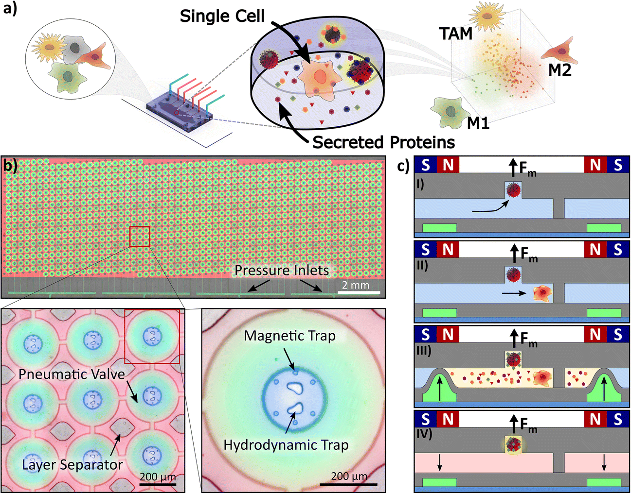 | ||
| Fig. 1 Microfluidic platform and procedure for single-immune cell analysis. a) Schematic abstract depicting the microdevice with microchambers to isolate single cells. We determine selected proteins secreted from macrophages treated with the supernatant from cancer cells (Mtreated), and M1- and M2-polarized macrophages. b) Image of the microfluidic platform with 1084 microchambers filled with fluorescent dyes for visualization. Four separate pressure inlets, visible at the bottom of the image as green lines, parallelizing four different experimental conditions on one platform. Left zoomed-in image: Every microchamber has a volume of 0.2 nL (ø = 110 μm) and can be isolated by pneumatically activated valves. The two-layer microfluidic PDMS chip is stabilized by pillars (layer separators). Right zoomed-in image: Inside each microchamber one centrally located hydrodynamic trap is surrounded by six magnetic traps, i.e., six round indents in the ceiling of the chamber. c) Side view of a microchamber to illustrate the procedure; I) each magnetic trap captures exactly one magnetic bead and retains it even if the microfluidic valves are opened. II) The hydrodynamic traps capture single cells depending on their size. III) The hydraulic pressure valves isolate every chamber from surrounding media by deflecting a thin PDMS membrane to the ceiling of the microchannel when pressure is applied. The secreted proteins are captured by the primary antibody immobilized on the bead’s surface. IV) After washing and adding secondary antibodies and a detection fluorophore, proteins are quantified based on the fluorescence intensity of the bead. | ||
To enable brightfield microscopy, we further optimized the placement of the magnets to obtain a homogeneous magnetic field across the microdevice (Fig. 2). We simulated various arrangements of magnet geometries and positions to optimize the magnetic flux density in the area of the microfluidic chip (Fig. 2c). Based on these simulations, we designed and 3D printed an optimized magnet frame, which mounts 14 neodymium magnets above and around the microfluidic chip, while the central area is left open to enable illumination of the microchamber array (Fig. 2b). Additionally, we added five pins to the magnet frame which connect to five holes on the microfluidic platform. This guaranteed an exact placement of the magnets in regard to the microchambers inside the microfluidic device in all three dimensions. We characterized the bead capture efficiency at the concentration provided by the manufacturer and at a volume flow rate of 1 μl min−1. Here we defined the bead capture efficiency as the percentage of the number of traps containing at least one bead. The bead capture efficiency varied in the range of 82% to 91% with an average of 88% (Fig. 2d). The cells were introduced into the chip after the beads were captured with a flow rate of 2 μl min−1. The capture efficiency of at least one cell inside a microchamber varied in the range of 40% to 71% with an average of 61% (Fig. 2e). The single-cell capture efficiency was lower at an average of 35%, which is primarily due to the propensity of macrophages to cluster in the hydrodynamic traps. Although the probability of having all bead types and exactly one cell in a chamber was low (∼3.4%), the platform provided results from ∼54% (∼585) of all chambers, since chambers with cells co-captured with one or two types of beads are still useful for single-cell analysis.
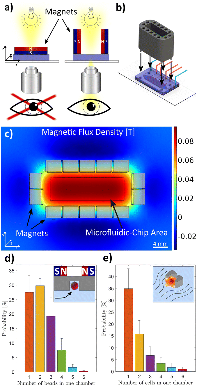 | ||
| Fig. 2 Magnet mount and platform characterization. a) The magnets are placed around the microfluidic chip with the same magnetic pole directed towards the centre to increase the magnetic flux density in the region of the chip. b) A 3D-printed magnet mount holds the magnets 4.5 mm above the microfluidic chip. Five pins are used to place the mount precisely on the microfluidic chip in reference to the microchambers inside the chip. c) The magnetic flux density in the z-direction is depicted 4.5 mm below the magnets. It shows a homogeneous magnetic flux density in the area of the microchambers (black rectangle) which is 4.5 mm below the magnets. Each light grey rectangle represents a magnet with dimensions of 3 × 4 × 20 mm. d) Occupancy of microchambers with magnetic beads of 6.5 μm diameter. The inset shows a schematic of a magnetic bead trap. e) Occupancy of cells in the microchambers. The inset shows a schematic of a hydrodynamic cell trap. | ||
Characterization of the bead-based assay
To calibrate the fluorescence signal to the protein level, we established the barcode region and the standard dilution curve of various proteins with functionalized beads. Every microchamber was imaged in bright field and epifluorescence using an automated microscope (Fig. 3a and b). Image analysis was conducted in an automated fashion with MATLAB. The fluorescence intensities in the far-red spectrum were used to determine the barcode of the beads (Fig. 3c). For protein quantification based on fluorescence intensity, we conducted experiments with various protein concentrations to obtain calibration curves (Fig. 3d). The limit of detection (LOD) was determined by adding the average bead intensities with three times their standard deviation at 0 ng mL−1. The LOD for TNF-α was 0.2 ng mL−1 which converts into ∼1250 molecules per single chamber, and the LODs were 1.5 ng mL−1 and 0.5 ng mL−1 for VEGF and IL-10, respectively. | ||
| Fig. 3 Barcoded magnetic beads and calibration curves. a) Microscopy images of a microchamber containing three magnetic beads with different barcodes. Every image is taken at different wavelengths to distinguish between the fluorophores inside the beads as well as the fluorescently tagged detection antibody. The barcode is encoded with fluorophores emitting in the far-red spectrum (658 nm and 725 nm) whereas the readout fluorophore emits in the yellow spectrum (590 nm). b) Overlayed images of a microchamber. c) The barcode of a bead is represented by different intensity ratios in the far-red spectrum. Each region in the 2D plot can be correlated to a primary antibody on the bead. d) On-chip calibration curves for the three investigated proteins. The dashed line indicates the limit of detection (LOD). | ||
The ratio between the volumes of the analyte per functionalized bead is drastically different in our microchambers (∼0.2 nL per bead) compared to the bulk assay (∼8 nL per bead). Therefore, at the same protein concentration, the number of analytes per bead is 40 times less than in the 96 well plate, resulting in a 40 times lower LOD. Taking this factor into account, the LOD reached on-chip is comparable to the LOD provided by the supplier. The results demonstrate that detection at low concentrations is possible, and we can reliably distinguish between different protein levels up to a concentration of several hundred ng mL−1. Based on the calibration curves, we can quantify the number of proteins the cell secretes by correlating the fluorescence intensity to the protein concentration.
Confirmation of the cell viability
The metabolic activity of entrapped cells on-chip was tested by adding alamarBlue™ to the media shortly before introducing them into the microfluidic device (Fig. 4a). The cells inside the microchamber reduced the resazurin of the alamarBlue™ to resorufin which is brightly fluorescent in the yellow spectrum. Resorufin was contained in the microchamber and up-concentrated because of the isolation of the cells and their secretion product. The images were taken 30 minutes after capturing and isolating the cells, which yielded a clear difference between chambers containing a cell or no cell (Fig. 4a). This implied that the cells were alive and still metabolically active after capture and isolation. Furthermore, this result showed that the microchambers isolated the cells and prevented the leakage of alamarBlue™ from one chamber to the next. This was additionally confirmed by secretion measurements of chambers containing at least one cell and chambers without any cell (Fig. S1†). The chambers without cells showed readouts below the detection limit of the assay implying no cross contamination of the pneumatically activated valves from the highly secreting cells in neighbouring chambers.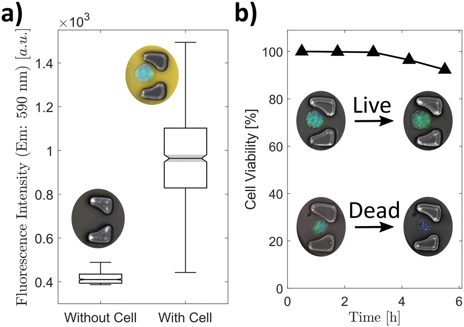 | ||
| Fig. 4 On-chip metabolic activity and cell viability. a) alamarBlue™, a fluorogenic assay, was used to visualize the metabolic activity of the cell on-chip. b) The cell viability on-chip was established by observing the membrane permeability with a live cell stain (blue) and a stain for ROS (green), n = 663. | ||
We measured the intracellular reactive oxygen species (ROS) of macrophages in bulk culture (off-chip) and isolated them in microchambers (on-chip) to analyse the stress response of the cell after capturing and compartmentalization (Fig. S2†). The ROS level of the cell in the bulk culture is slightly higher than in the cells captured in the microchambers. This is largely due to unspecific ROS contained in the media which increases the overall readout signal. For automatic cell recognition, we added a viability stain to brightly stain living and membrane-intact cells. Both stains were utilized to establish the membrane permeability of the cells over an extended period (Fig. 4b). The cells with a permeable, leaky membrane showed no fluorescence after more than 5 hours whereas the cells with an intact membrane showed a still high fluorescence signal. After this incubation time, 92% of the cells had an intact membrane.
Polarization of the macrophages
Unpolarized macrophages were derived from the THP-1 cell line and further activated to the M1 phenotype and the M2 phenotype by adding IFN-γ/LPS and IL-4/IL-13 for 12 h, respectively (Fig. 5a). We were able to distinguish the differently polarized macrophages based on their secretion profile measured in the bulk culture media (Fig. 5b, S3 and S4†). As expected, the M1 macrophages show an increased secretion of TNF-α (p < 0.001) whereas the M2 macrophages secrete more IL-10 (p < 0.001) compared to the unpolarized macrophages (control). All three phenotypes secreted VEGF, with secretion highest in the M1 macrophages. This is interesting, as VEGF promotes angiogenesis and hence tumour growth. Our observation is in accordance with prior findings. The use of LPS for polarization has been shown to lead to increased VEGF secretion (see also Fig. S4† depicting the results for alternative polarization conditions).33 | ||
| Fig. 5 Macrophage differentiation. a) Microscopy images of unpolarized macrophages (control) (I), M1 macrophages (II), and M2 macrophages (III) (green: ROS stain, blue: live cell stain). The scale bars in the images are 100 μm and in the insets 50 μm. b) Protein secretion of the differentiated macrophages evaluated with an on-bead immunoassay from the bulk culture supernatant (N = 3, pooled). | ||
On-chip secretion studies
Next, we captured, isolated, and incubated the polarized macrophages on the microfluidic platform and measured the secreted signalling proteins from single cells (Fig. 6a and b). Due to the extreme sensitivity of the platform, we were able to characterize the macrophages according to their polarization. The M1 macrophages show a high TNF-α secretion (median: 2.23 ng ml−1) as in the bulk culture and are clearly distinguishable from the M2 macrophages based on this secretion. In contrast, the secretion of IL-10 by the M2 macrophages (median: 0.78 ng ml−1) is not significantly higher than that of the M1 macrophages (median: 0.75 ng ml−1). The reduced IL-10 secretion of the M2 macrophages can be explained by the isolation of single cells, preventing the effect of paracrine signalling from the bulk population, which can impact the secretion of signalling proteins.34 | ||
| Fig. 6 The macrophage characterization based on single-cell protein secretion. a) The proteins secreted by captured and isolated macrophages were measured with an immunoassay. The grey datapoints show secretion values below the detection limit (n ≥ 114). M1 macrophages and M2 macrophages are polarized by the addition of defined signalling factors, whereas macrophages polarized by the culture medium from cancer cells are denoted as Mtreated. b) A microscopy image of an example microchamber containing one macrophage with three different bead types. c)–e) show the multiplex expression of the proteins from single macrophages (n ≥ 47, n ≥ 74, and n ≥ 66). The colour overlays are the regions in which most of the datapoints of the corresponding cells are located. Outliers are not depicted (Fig. S7† includes all datapoints). | ||
Additionally, we incubated unpolarized macrophages in the up-concentrated supernatant of breast cancer cells (MCF-7 cell line) to simulate the impact of the TME on the polarization of macrophages.35 These macrophages show a protein pattern similar to M2 macrophages with a significantly increased expression of all measured proteins (median IL-10: 1,12 ng mL−1, TNF-α: 1.43 ng mL−1, VEGF: 4.81 ng mL−1). Notably, the MCF-7 secretome is missing the factors commonly used to polarize macrophages (i.e., INF-γ, IL-4, and IL-13),3 however, it contains a high level of VEGF (Fig. S5†). In the TME, VEGF secreted from the cancer cells supports the recruitment of macrophages, which are subsequently polarized towards M2-like macrophages (TAMs).36,37 Therefore, we hypothesize that the VEGF from MCF-7 cells is a factor that is involved in the polarization of the macrophages towards TAMs. In addition, and in line with previous observations,35 TAMs secrete in turn higher amounts of VEGF when polarized in VEGF-containing media compared to polarization in VEGF-depleted media.
Multiplexed analysis highlights the correlations between signalling molecules in individual cells, which is only possible by single-cell analysis. (Fig. 6c–e and 3D plot in Fig. S6†). Secretion of the tumour suppressive protein TNF-α is upregulated when the tumour-promoting proteins IL-10 and VEGF are low (Fig. 6c and d). Conversely, the tumour-promoting proteins IL-10 and VEGF are more highly expressed in cells that do not express the tumour-suppressive protein TNF-α. The M2 macrophages mostly secrete either IL-10 or VEGF at higher amounts but not at the same time which indicates that there are at least two subpopulations of M2 macrophages. This contrasts with the macrophages treated with the breast cancer supernatant (Mtreated) which mostly secreted both at the same time (Fig. 6e).
These results demonstrate that our system is well suited to analyse low-abundance secreted proteins at the single-cell level, which we showed by distinguishing between polarized macrophages. The hydrodynamic traps enabled the tag free capture of single cells whereas the optimized magnet mount permitted the simultaneous retention and observation of the beads and cells. The capturing of magnetic beads in small cavities facilitated the automation of imaging and improved signal acquisition. The developed platform showed its capability to study macrophages subjected to cancer cell-derived signalling factors which will deepen the understanding of cell-to-cell signalling and the role of macrophages in tumour progression. However, the limitation of the platform was the random trapping of beads in the small magnetic traps, which can be improved by increasing the number of magnetic traps per chamber or increasing the bead concentration.
Conclusions
Macrophage polarization towards TAMs as well as the resulting changes in the signalling proteins is a highly complex process. It is well-known that macrophages are not a uniform population, and detection of subpopulations requires analysis at the single-cell level. Here, we introduce a microfluidic method for capturing polarized macrophages and the analysis of selected signalling proteins. As we isolate cells, paracrine signalling is prevented at the time of accumulation of the signalling proteins. We confirm that M1, M2, and macrophages treated with the supernatant from cancer cells can be distinguished by their secretion profile, but we also find a very heterogeneous population on the individual cell level with cells secreting at high levels and others without detectable signalling proteins. Besides the analysis of macrophages, the microfluidic device is very versatile and can be used for other cell types and the analysis of other secreted factors or exosomes at the single-cell level. The combination of hydrodynamic traps for size-based cell capturing and magnetic traps for immobilization of beads enables efficient co-encapsulation of cells and functionalized beads. The high sensitivity of immunoassays in a pL chamber allows for accumulation and quantification of proteins secreted at very low levels. There is a growing library of commercially available magnetic beads with many different barcodes for numerous targets. Coupled to the method presented herein, this will allow for multiplexed and quantitative measurement of a variety of different signalling proteins at the single-cell resolution.Author contributions
C. D. designed and fabricated the device, performed all experiments on-chip and evaluated all data. E. H. provided the macrophages and performed the off-chip characterization. P. S. D. conceptualized and supervised the work. C. D. and P. S. D. wrote the manuscript.Conflicts of interest
There are no conflicts to declare.Acknowledgements
We thank R. Strutt for proofreading the manuscript. We thank the cleanroom facility (ETH Zurich) for access and support. Financial support of the European Research Council (ERC CoG No. 681587) and Personalized Medicine Basel (Grant No. PMB-02-19) is gratefully acknowledged.References
- G. Altan-Bonnet and R. Mukherjee, Nat. Rev. Immunol., 2019, 19, 205–217 CrossRef CAS PubMed.
- P. Jiang, Y. Zhang, B. Ru, Y. Yang, T. Vu, R. Paul, A. Mirza, G. Altan-Bonnet, L. Liu, E. Ruppin, L. Wakefield and K. W. Wucherpfennig, Nat. Methods, 2021, 18, 1181–1191 CrossRef CAS PubMed.
- K. Chen, L. Satlof, G. Stoffels, U. Kothapalli, N. Ziluck, M. Lema, L. Poretsky and D. Avtanski, Data Brief, 2020, 28, 104798 CrossRef PubMed.
- C. Varol, A. Mildner and S. Jung, Annu. Rev. Immunol., 2015, 33, 643–675 CrossRef CAS PubMed.
- M. Gerlinger, A. J. Rowan, S. Horswell, J. Larkin, D. Endesfelder, E. Gronroos, P. Martinez, N. Matthews, A. Stewart, P. Tarpey, I. Varela, B. Phillimore, S. Begum, N. Q. McDonald, A. Butler, D. Jones, K. Raine, C. Latimer, C. R. Santos, M. Nohadani, A. C. Eklund, B. Spencer-Dene, G. Clark, L. Pickering, G. Stamp, M. Gore, Z. Szallasi, J. Downward, P. A. Futreal and C. Swanton, N. Engl. J. Med., 2012, 366, 883–892 CrossRef CAS PubMed.
- A. P. Patel, I. Tirosh, J. J. Trombetta, A. K. Shalek, S. M. Gillespie, H. Wakimoto, D. P. Cahill, B. V. Nahed, W. T. Curry, R. L. Martuza, D. N. Louis, O. Rozenblatt-Rosen, M. L. Suvà, A. Regev and B. E. Bernstein, Science, 2014, 344, 1396–1401 CrossRef CAS PubMed.
- X. Geeraerts, E. Bolli, S.-M. Fendt and J. A. van Ginderachter, Front. Immunol., 2017, 8, 289 Search PubMed.
- T. Hourani, J. A. Holden, W. Li, J. C. Lenzo, S. Hadjigol and N. M. O'Brien-Simpson, Front. Oncol., 2021, 11, 1–20 Search PubMed.
- Y. Pan, Y. Yu, X. Wang and T. Zhang, Front. Immunol., 2020, 11, 583084 CrossRef CAS PubMed.
- P. J. Murray, J. E. Allen, S. K. Biswas, E. A. Fisher, D. W. Gilroy, S. Goerdt, S. Gordon, J. A. Hamilton, L. B. Ivashkiv, T. Lawrence, M. Locati, A. Mantovani, F. O. Martinez, J. L. Mege, D. M. Mosser, G. Natoli, J. P. Saeij, J. L. Schultze, K. A. Shirey, A. Sica, J. Suttles, I. Udalova, J. A. van Ginderachter, S. N. Vogel and T. A. Wynn, Immunity, 2014, 41, 14–20 CrossRef CAS PubMed.
- L.-X. Wang, S.-X. Zhang, H.-J. Wu, X.-L. Rong and J. Guo, J. Leukocyte Biol., 2019, 106, 345–358 CrossRef CAS PubMed.
- B. Ruffell, D. Chang-Strachan, V. Chan, A. Rosenbusch, C. M. T. Ho, N. Pryer, D. Daniel, E. S. Hwang, H. S. Rugo and L. M. Coussens, Cancer Cell, 2014, 26, 623–637 CrossRef CAS PubMed.
- J. Zhou, Z. Tang, S. Gao, C. Li, Y. Feng and X. Zhou, Front. Oncol., 2020, 10, 188 CrossRef PubMed.
- Z. Duan and Y. Luo, Signal Transduction Targeted Ther., 2021, 6, 1–21 CrossRef PubMed.
- P. Pathria, T. L. Louis and J. A. Varner, Trends Immunol., 2019, 40, 310–327 CrossRef CAS PubMed.
- Z. X. Liao, Y. C. Fa, I. M. Kempson and S. J. Tseng, Bioconjugate Chem., 2019, 30, 2697–2702 CrossRef CAS PubMed.
- S. M. Pyonteck, L. Akkari, A. J. Schuhmacher, R. L. Bowman, L. Sevenich, D. F. Quail, O. C. Olson, M. L. Quick, J. T. Huse, V. Teijeiro, M. Setty, C. S. Leslie, Y. Oei, A. Pedraza, J. Zhang, C. W. Brennan, J. C. Sutton, E. C. Holland, D. Daniel and J. A. Joyce, Nat. Med., 2013, 19, 1264–1272 CrossRef CAS PubMed.
- R. N. Zare and S. Kim, Annu. Rev. Biomed. Eng., 2010, 12, 187–201 CrossRef CAS PubMed.
- S. F. Berlanda, M. Breitfeld, C. L. Dietsche and P. S. Dittrich, Anal. Chem., 2021, 93, 311–331 CrossRef CAS PubMed.
- L. Chappell, A. J. C. Russell and T. Voet, Annu. Rev. Genomics Hum. Genet., 2018, 19, 15–41 CrossRef CAS PubMed.
- S. Vyawahare, A. D. Griffiths and C. A. Merten, Chem. Biol., 2010, 17, 1052–1065 CrossRef CAS PubMed.
- P. S. Dittrich and A. Manz, Nat. Rev. Drug Discovery, 2006, 5, 210–218 CrossRef CAS PubMed.
- E. Z. Macosko, A. Basu, R. Satija, J. Nemesh, K. Shekhar, M. Goldman, I. Tirosh, A. R. Bialas, N. Kamitaki, E. M. Martersteck, J. J. Trombetta, D. A. Weitz, J. R. Sanes, A. K. Shalek, A. Regev and S. A. McCarroll, Cell, 2015, 161, 1202–1214 CrossRef CAS PubMed.
- V. Chokkalingam, J. Tel, F. Wimmers, X. Liu, S. Semenov, J. Thiele, C. G. Figdor and W. T. S. Huck, Lab Chip, 2013, 13, 4740–4744 RSC.
- Y. Bounab, K. Eyer, S. Dixneuf, M. Rybczynska, C. Chauvel, M. Mistretta, T. Tran, N. Aymerich, G. Chenon, J. F. Llitjos, F. Venet, G. Monneret, I. A. Gillespie, P. Cortez, V. Moucadel, A. Pachot, A. Troesch, P. Leissner, J. Textoris, J. Bibette, C. Guyard, J. Baudry, A. D. Griffiths and C. Védrine, Nat. Protoc., 2020, 15, 2920–2955 CrossRef CAS PubMed.
- M. N. Hsu, S. C. Wei, S. Guo, D. T. Phan, Y. Zhang and C. H. Chen, Small, 2018, 14, 1–11 CrossRef PubMed.
- D. M. Rissin, C. W. Kan, T. G. Campbell, S. C. Howes, D. R. Fournier, L. Song, T. Piech, P. P. Patel, L. Chang, A. J. Rivnak, E. P. Ferrell, J. D. Randall, G. K. Provuncher, D. R. Walt and D. C. Duffy, Nat. Biotechnol., 2010, 28, 595–599 CrossRef CAS PubMed.
- L. Armbrecht, R. S. Müller, J. Nikoloff and P. S. Dittrich, Microsyst. Nanoeng., 2019, 5, 55 CrossRef CAS PubMed.
- L. Armbrecht and P. S. Dittrich, Anal. Chem., 2017, 89, 2–21 CrossRef CAS PubMed.
- Y. Lu, J. J. Chen, L. Mu, Q. Xue, Y. Wu, P. H. Wu, J. Li, A. O. Vortmeyer, K. Miller-Jensen, D. Wirtz and R. Fan, Anal. Chem., 2013, 85, 2548–2556 CrossRef CAS PubMed.
- A. J. Kaestli, M. Junkin and S. Tay, Lab Chip, 2017, 17, 4124–4133 RSC.
- Y. Lu, Q. Xue, M. R. Eisele, E. S. Sulistijo, K. Brower, L. Han, E. A. D. Amir, D. Pe'er, K. Miller-Jensen and R. Fan, Proc. Natl. Acad. Sci. U. S. A., 2015, 112, E607–E615 CrossRef CAS PubMed.
- N. Koide, E. Odkhuu, Y. Naiki, B. Tsolmongyn, K. Ito, T. Komatsu, T. Yoshida and T. Yokochi, Innate Immun., 2014, 20, 816–825 CrossRef PubMed.
- Q. Xue, Y. Lu, M. R. Eisele, E. S. Sulistijo, N. Khan, R. Fan and K. Miller-Jensen, Sci. Signaling, 2015, 8, 381 CrossRef PubMed.
- S. Okikawa, Y. Morine, Y. Saito, S. Yamada, K. Tokuda, H. Teraoku, K. Miyazaki, S. Yamashita, T. Ikemoto, S. Imura and M. Shimada, Oncol. Rep., 2022, 47, 71 CrossRef CAS PubMed.
- M. L. Squadrito and M. De Palma, Mol. Aspects Med., 2011, 32, 123–145 CrossRef CAS PubMed.
- J. S. Lewis, R. J. Landers, J. C. E. Underwood, A. L. Harris and C. E. Lewis, J. Pathol., 2000, 192, 150–158 CrossRef CAS PubMed.
- J. R. Choi, J. H. Lee, A. Xu, K. Matthews, S. Xie, S. P. Duffy and H. Ma, Lab Chip, 2020, 20, 4539–4551 RSC.
- X. An, V. G. Sendra, I. Liadi, B. Ramesh, G. Romain, C. Haymaker, M. Martinez-Paniagua, Y. Lu, L. G. Radvanyi, B. Roysam and N. Varadarajan, PLoS One, 2017, 12, 8 Search PubMed.
Footnote |
| † Electronic supplementary information (ESI) available. See DOI: https://doi.org/10.1039/d2lc00891b |
| This journal is © The Royal Society of Chemistry 2023 |