
 Open Access Article
 This Open Access Article is licensed under a Creative Commons Attribution-Non Commercial 3.0 Unported Licence
Highly active ZIF-8@CNT composite catalysts as cathode materials for anion exchange membrane fuel cells†
Rohit
Kumar
 a,
Marek
Mooste
a,
Zubair
Ahmed
a,
Srinu
Akula
a,
Ivar
Zekker
a,
Margus
Marandi
a,
Maike
Käärik
a,
Jaan
Leis
a,
Arvo
Kikas
b,
Alexey
Treshchalov
b,
Markus
Otsus
b,
Jaan
Aruväli
c,
Vambola
Kisand
b,
Aile
Tamm
b and
Kaido
Tammeveski
*a
a,
Marek
Mooste
a,
Zubair
Ahmed
a,
Srinu
Akula
a,
Ivar
Zekker
a,
Margus
Marandi
a,
Maike
Käärik
a,
Jaan
Leis
a,
Arvo
Kikas
b,
Alexey
Treshchalov
b,
Markus
Otsus
b,
Jaan
Aruväli
c,
Vambola
Kisand
b,
Aile
Tamm
b and
Kaido
Tammeveski
*a
aInstitute of Chemistry, University of Tartu, Ravila 14a, 50411 Tartu, Estonia. E-mail: kaido.tammeveski@ut.ee
bInstitute of Physics, University of Tartu, W. Ostwald Str. 1, 50411 Tartu, Estonia
cInstitute of Ecology and Earth Sciences, University of Tartu, Vanemuise 46, 51014 Tartu, Estonia
First published on 6th September 2023
Abstract
Developing non-precious metal-based inexpensive and highly active electrocatalysts for the oxygen reduction reaction (ORR) in alkaline media is important for fuel cell applications. Herein, we report a simple and effective synthesis of transition-metal-doped zeolitic imidazolate framework-8 (ZIF-8) and carbon nanotube (CNT) composite catalysts (ZIF-8@CNT) prepared via high-temperature pyrolysis at 900 °C. The catalysts were characterized using different physicochemical techniques and employed as cathode materials in anion exchange membrane fuel cells (AEMFC). The prepared metal-free (ZNT-900), single-metal-doped (Fe-ZNT-900, Co-ZNT-900) and binary-metal-doped (Fe1Co1-ZNT-900, Fe1Co2-ZNT-900) catalysts had a sufficient amount of N-doping with the presence of FeCo moieties in the carbon skeleton of the latter two materials. N2 adsorption–desorption isotherms showed that all the prepared catalysts possess a sufficient Brunauer–Emmett–Teller surface area with more micropores present in ZNT-900, while a combined micro–mesoporous structure was obtained for transition-metal-doped catalysts. Binary-metal-doped catalysts showed the highest number of ORR-active sites (pyridinic-N, pyrrolic-N, graphitic-N, M–Nx) and exhibited a half-wave potential (E1/2) of 0.846 and 0.847 V vs. RHE for Fe1Co1-ZNT-900 and Fe1Co2-ZNT-900, respectively, which surpassed that of the commercial Pt/C catalyst (E1/2 = 0.834 V). In H2–O2 AEMFCs, the Fe1Co2-ZNT-900 catalyst delivered a maximum power density (Pmax) of 0.171 W cm−2 and current density at 0.5 V (j0.5) of 0.326 A cm−2, which is very close to that of the Pt/C catalyst (Pmax = 0.215 W cm−2 and j0.5 = 0.359 A cm−2). The prepared ZIF-8@CNT catalysts showed remarkable electrocatalytic ORR activity in 0.1 M KOH solution and fuel cell performance comparable to that of the benchmark Pt/C catalyst.
Keywords: Rotating disk electrode; Anion exchange membrane fuel cell; Zeolitic imidazolate framework; Non-precious metal catalyst; Oxygen reduction reaction.
1. Introduction
To mitigate global warming, current research and development have received a lot of attention in the field of renewable energy generation.1–5 Among promising electrochemical energy conversion devices are anion exchange membrane fuel cells (AEMFC) that use O2/air as an oxidant at the cathode to produce electric power and some heat.6 However, the sluggish kinetics of cathodic oxygen reduction reaction (ORR) and insufficient durability are significant disadvantages in AEMFC practical applications.7,8 Currently, platinum (Pt) represents the pinnacle of electrocatalytic ORR;9 however, Pt-based catalysts are restricted by its scarcity, vulnerability to carbon monoxide (CO) poisoning, etc.10 Research on non-platinum catalyst materials is crucial for the widespread development of AEMFCs.11–15 To date, numerous approaches have been used to make progress in this direction to increase the density15 of ORR-active sites via introducing multiple active catalyst centres.16 Various transition-metal-based electrocatalysts have been explored as cost-efficient materials for catalysing the ORR in alkaline medium; nonetheless, it is challenging to identify a single-metal electrocatalyst as a counterpart to Pt group metal catalysts.17–19 In this regard, transition metal and nitrogen co-doped carbon (M–N–C)-based catalyst materials have attracted great attention due to their excellent ORR activity in alkaline media, which sometimes surpasses that of the Pt/C catalyst.20 The M–N–C catalysts are generally prepared by pyrolysing the carbon-, nitrogen- and transition-metal-containing precursors.21 Typically, M–N4 species are believed to be the most active ORR centres.22 According to many reports, the better performance of single-atom-based Fe–N–C catalysts usually coming from the well-established Fe–Nx or porphyrin-like Fe–N4 active sites obtained after high-temperature pyrolysis.22–24 Bimetallic catalysts with controlled electronic structures and enhanced synergistic effects also show extremely strong potential for ORR application. Bimetallic electrocatalysts are based on the structural modification between two metal atoms due to which the resulting chemical structure is expected to have enhanced electronic properties favourable for increased electrocatalytic activity.25,26 Reports suggest that the bimetallic sites are believed to facilitate the O–O bond cleavage via a bridge cis adsorption of ORR intermediates and also improve the durability of M–N–C sites for the ORR.27 Therefore, the construction of hybrid electrode materials, especially those made from Co and Fe metal sources (including Fe/Co bimetallic oxides and alloys), has become the main focus nowadays.28–30 These bimetallic catalysts can be synthesised through thermal conversion of bimetallic sources with various Fe/Co ratios. In recent years, to reduce the cost, non-precious-metal catalysts derived from Co, Fe, Mn, etc. are usually used as anode as well as cathode catalysts for various applications.31 Additionally, metal–organic frameworks (MOFs) have significant advantages in catalyst tuning and structure optimization and their derivatives usually have highly dispersed accessible active sites, improved charge transfer networks, and high porosity for efficient mass transfer of reactants.31–33 Zeolitic imidazolate framework-8 (ZIF-8), as a branch of MOFs, has gained much attention as a template for preparing carbon-based catalysts due to its hierarchical porosity, high nitrogen content, excellent thermal and electrochemical stability, and volatile characteristics of Zn at higher temperatures.34,35 This further enhances doping of nitrogen in the carbon skeleton, which changes the charge distribution and helps O2 adsorption on the active sites.36,37To date, a vast array of monometallic and bimetallic Fe- and Co-doped nitrogen-containing nanocarbon catalysts have been researched in AEMFCs. For instance, our group reported the potential role of Fe and Co doping on graphene/CNT composite catalysts in enhancing the power output of AEMFCs.38 The prepared composite carbon catalysts showed an excellent ORR activity with a half-wave potential (E1/2) reaching 0.81 V vs. RHE, and an AEMFC power output of 0.64 W cm−2 was achieved for the bimetallic Fe- and Co-doped catalysts. Another study was reported with Fe- and Co doped mesoporous carbon catalysts applied as cathode materials in AEMFCs. The bimetallic catalysts reached an E1/2 value of 0.86 V and a maximum power density of 0.92 W cm−2 in AEMFCs.39 Fe and Co metal anchored ZIF-8-based carbon catalysts are not extensively studied in AEMFCs. The anion exchange membrane (AEM) plays a crucial role in overall AEMFC performance and many studies so far have been performed with the Aemion+ AEM and ionomer, which offers a lower mass transport resistance and water management throughout the AEMFC.40 To our knowledge, commercial Aemion+® 15 μm AEM has not been tested in AEMFC and this study is the first of its kind to show the potential role of the Aemion+® 15 μm membrane in AEMFC performance. To our knowledge, a hybrid composite of ZIF-8 and CNT derived Fe–Co catalysts and their demonstration in the AEMFC is reported for the first time.
Herein, we report highly dispersed monometallic (Fe or Co) and bimetallic FeCo catalysts prepared by the composite of CNTs and N-rich ZIF-8. The resulting catalyst materials exhibit superior electron transfer properties and high electrocatalytic activity towards the ORR. Amongst the ZIF-8@CNT catalysts, FeCo bimetallic/N-doped CNT catalysts reached the highest E1/2 value and surpassed the performance of commercial Pt/C (20 wt% Pt) catalysts and most of the reported Fe/Co-based MOF catalysts in 0.1 M KOH solution. The performance of bimetallic FeCo-based catalysts was further investigated at the AEMFC cathode, and for Fe1Co2-ZNT-900 (Fe/Co at a ratio of 1![[thin space (1/6-em)]](https://www.rsc.org/images/entities/char_2009.gif) :2, respectively) the peak power density of 0.171 W cm−2 was obtained, which is close to that of Pt/C using the Aemion+® 15 μm AEM for AEMFC. The adopted synthesis approach to design efficient FeCo bimetallic cathode catalysts for AEMFC applications would drive towards sustainable AEMFC technologies.
:2, respectively) the peak power density of 0.171 W cm−2 was obtained, which is close to that of Pt/C using the Aemion+® 15 μm AEM for AEMFC. The adopted synthesis approach to design efficient FeCo bimetallic cathode catalysts for AEMFC applications would drive towards sustainable AEMFC technologies.
2. Results and discussion
2.1. Physicochemical characterisation of ZIF-8@CNT catalysts
Fig. 1a shows the crystallographic features of as-prepared ZIF-8@CNT catalysts revealed by X-ray diffraction (XRD) analysis. The appearance of broad diffraction peaks at 25.6° and 43.08° represents the (002) and (100) graphitic planes (PDF-04-020-4354), proving that ZIF-8@CNT catalysts have been successfully pyrolysed and carbonised.41 At high-temperature annealing (900 °C), amorphous carbon disappears and graphitised carbon peaks are dominant.42 The characteristic peaks located at 30.13° (220), 35.55° (311), 57.28° (511) and 62.94° (440) suggest the presence of magnetic Fe3O4 nanoparticles (PDF-00-039-1346).43 Also, a peak around 44.67° can be assigned to the α-Fe body-centred (110) plane (PDF-04-007-9753).44 Two characteristic peaks at 44.89° and 65.4° can be attributed to FeCo alloys residing in the (111) and (200) lattice planes (PDF-00-049-1568).45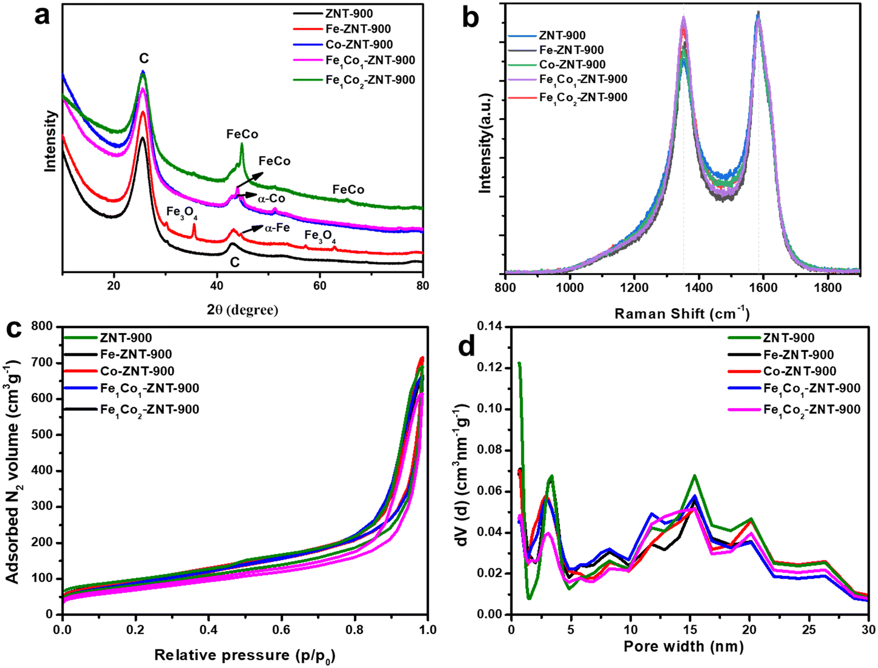 | ||
| Fig. 1 (a) XRD patterns, (b) Raman spectra, (c) N2 adsorption–desorption isotherms and (d) pore size distribution for various transition-metal-doped and metal-free ZIF-8@CNT-derived catalysts. | ||
The defects in the as-synthesised ZIF-8@CNT catalysts were analysed by Raman spectroscopy (Fig. 1b). The D band displayed at ∼1352 cm−1 shows the defects and disorders in the carbon lattice, and the G band at ∼1584 cm−1 reflects the E2g vibrations in the graphite-type lattice (sp2-hybridised carbon).46,47 For MWCNTs, the G band position is found to be higher than that of other carbon-based materials, which is reported mainly due to large compressive stress affecting the C![[double bond, length as m-dash]](https://www.rsc.org/images/entities/char_e001.gif) C bonds present in highly defective nanotube walls. Further deconvolution of the D and G bands provides additional information regarding the amorphic carbon nature. For instance, Daniel et al. presented polyurethane-derived Fe–N–C electrocatalysts for the ORR.48 The Raman spectra showed two broader peaks centred at ∼1350 and ∼1595 cm−1 indicating D and G bands, respectively, and were further deconvoluted to six Gaussian bands named I, D4, D1, D3, G and D2. However, deconvoluting Raman spectra in the case of MWCNTs is more complicated and is not often studied.49 It has been reported that the complex structure of CNTs with different scattering events happened due to weak out-of-plane modes, weak wall-to-wall interactions, and curvature of walls which makes their deconvolution quite challenging.50 As an example, all spectra were fitted following the five Voigt-shaped band model, where the G band (∼1585 cm−1) corresponds to the stretching vibrations of the sp2 carbon atoms in the ideal graphitic lattice; D1 (∼1350 cm−1, Lorentzian) to defect-activated breathing mode of aromatic rings; D2 (∼1610 cm−1, Gaussian) to disordered graphene layers at the surface of a graphitic crystal; D3 (∼1490 cm−1, Gaussian) to amorphous carbon and D4 (∼1210 cm−1, Gaussian) to disordered graphitic lattice. For instance, the deconvoluted Raman spectrum for Fe1Co2-ZNT-900 is presented in Fig. S2.† It should be considered that the commonly used ID/IG Raman band peak intensity ratio is rather appropriate to quantify the structural imperfection for the graphene samples. However, for highly disordered carbon materials, the Raman band commonly labelled as G is in fact a superposition of the G and D2 bands. This band overlap renders the ID/IG ratio an unreliable measure for the structural disorder of such materials.51 Therefore, to interpret the degree of structural disordering in ZIF@CNT catalysts, the parameter W (full-width at half-maximum (FWHM) of the D1 and G bands), ID1/IG (the ratio of the areas under the bands) and R2 = D1/(G + D1 + D2) (the ratio of the areas of indicated bands) were calculated as shown in Table S2.† The amorphous carbon represented by band D3 was found similar for all the catalyst materials. In fact, the change in intensities between the D and G bands is mostly due to a variation of the widths of the D1 and G bands. From the data in Table S2,† it can be concluded that the structural disorder increases steadily in the sequence of Fe-ZNT-900, ZNT-900, Co-ZNT-900, Fe1Co1-ZNT-900, and Fe1Co2-ZNT-900 samples. It has been reported that pyrolysis promotes the graphitisation of the materials in the presence of small amounts of transition metals, which is evident from the higher graphitic peaks obtained for metal-doped catalysts.52
C bonds present in highly defective nanotube walls. Further deconvolution of the D and G bands provides additional information regarding the amorphic carbon nature. For instance, Daniel et al. presented polyurethane-derived Fe–N–C electrocatalysts for the ORR.48 The Raman spectra showed two broader peaks centred at ∼1350 and ∼1595 cm−1 indicating D and G bands, respectively, and were further deconvoluted to six Gaussian bands named I, D4, D1, D3, G and D2. However, deconvoluting Raman spectra in the case of MWCNTs is more complicated and is not often studied.49 It has been reported that the complex structure of CNTs with different scattering events happened due to weak out-of-plane modes, weak wall-to-wall interactions, and curvature of walls which makes their deconvolution quite challenging.50 As an example, all spectra were fitted following the five Voigt-shaped band model, where the G band (∼1585 cm−1) corresponds to the stretching vibrations of the sp2 carbon atoms in the ideal graphitic lattice; D1 (∼1350 cm−1, Lorentzian) to defect-activated breathing mode of aromatic rings; D2 (∼1610 cm−1, Gaussian) to disordered graphene layers at the surface of a graphitic crystal; D3 (∼1490 cm−1, Gaussian) to amorphous carbon and D4 (∼1210 cm−1, Gaussian) to disordered graphitic lattice. For instance, the deconvoluted Raman spectrum for Fe1Co2-ZNT-900 is presented in Fig. S2.† It should be considered that the commonly used ID/IG Raman band peak intensity ratio is rather appropriate to quantify the structural imperfection for the graphene samples. However, for highly disordered carbon materials, the Raman band commonly labelled as G is in fact a superposition of the G and D2 bands. This band overlap renders the ID/IG ratio an unreliable measure for the structural disorder of such materials.51 Therefore, to interpret the degree of structural disordering in ZIF@CNT catalysts, the parameter W (full-width at half-maximum (FWHM) of the D1 and G bands), ID1/IG (the ratio of the areas under the bands) and R2 = D1/(G + D1 + D2) (the ratio of the areas of indicated bands) were calculated as shown in Table S2.† The amorphous carbon represented by band D3 was found similar for all the catalyst materials. In fact, the change in intensities between the D and G bands is mostly due to a variation of the widths of the D1 and G bands. From the data in Table S2,† it can be concluded that the structural disorder increases steadily in the sequence of Fe-ZNT-900, ZNT-900, Co-ZNT-900, Fe1Co1-ZNT-900, and Fe1Co2-ZNT-900 samples. It has been reported that pyrolysis promotes the graphitisation of the materials in the presence of small amounts of transition metals, which is evident from the higher graphitic peaks obtained for metal-doped catalysts.52
The more defect-rich carbon structure obtained for bimetallic ZIF-8@CNT catalysts offers a higher number of active centres to promote the ORR kinetics.53 The specific surface area and pore size distribution (PSD) of the ZIF-8@CNT catalysts were investigated via N2 adsorption–desorption isotherms and the Brunauer–Emmett–Teller (BET) theory, as shown in Fig. 1c and d, respectively. All the catalysts followed a combination of type I and III H3 hysteresis, which characteristically represents the presence of micro–mesoporous materials with a majority of mesopores according to IUPAC nomenclature.54 The density functional theory (DFT) specific surface area (SDFT) for the micropores (SDFT mic.) and mesopores (SDFT mes.) were estimated from N2 isotherms using a quenched solid DFT (QSDFT) equilibrium model for slit-type pores (Table 1).
| Catalysts | S BET (m2 g−1) | V micro (cm3 g−1) | V tot (cm3 g−1) | S DFT (mic.) (m2 g−1) | S DFT (mes.) (m2 g−1) |
|---|---|---|---|---|---|
| ZNT-900 | 290 | 0.07 | 0.65 | 189 | 172 |
| Fe-ZNT-900 | 334 | 0.07 | 0.66 | 145 | 170 |
| Co-ZNT-900 | 297 | 0.07 | 0.73 | 141 | 175 |
| Fe1Co1-ZNT-900 | 247 | 0.05 | 0.61 | 106 | 147 |
| Fe1Co2-ZNT-900 | 312 | 0.06 | 0.66 | 109 | 181 |
The ZNT-900 catalyst carried the highest volume of micropores and a lower BET surface area (SBET). Since the ZNT-900 material contains an equal amount of CNTs along with ZIF-8, after annealing at 900 °C Zn evaporates, creating hollow ZIF crystals, and the ends of the CNTs start to close, which results in a decrease in its SBET.55 CNTs tend to form bundles due to van der Waals interactions and only the outer area, interstitial channels, and grooves are the available sites left for O2 adsorption, which in turn decreases the overall surface area of the material. The DFT micropores/mesopores surface area ratio was close to 1.1 for ZNT-900, representing that both micropores and mesopores were equally present in the catalyst materials. The presence of Co did not affect SBET because of the presence of more mesopores instead of micropores. A similar trend can be observed for the Fe1Co1-ZNT-900 catalyst, in which bimetal doping obstructed the micropores and increased the volume of mesopores, resulting in decreasing the SBET even further to 247 m2 g−1. This can be attributed to the lower total pore volume (0.61 cm3 g−1) and micropore volume (0.05 cm3 g−1). Fe1Co2-ZNT-900 showed an increase in the BET surface area up to 312 m2 g−1. In general, all the ZIF-8@CNT catalysts possess similar textural properties, especially the PSD, which shows the existence of both micro- and mesopores in the catalyst materials (Table 1). However, a small difference in the micropore/mesopore ratio can be observed for ZIF-8@CNT catalysts. These porous materials have a high potential for use as efficient electrocatalysts for the ORR and fuel cell applications.
The morphology and dopant distribution over the catalyst surface were studied in more detail using scanning electron microscopy (SEM) and scanning transmission electron microscopy (STEM) analysis. The surface morphologies of ZIF-8@CNT catalysts obtained from SEM images are shown in Fig. 2. All the catalysts showed similar morphologies with a tubular arrangement of CNTs covering the ZIF surface. The outer diameter of CNTs was in the range of 8–12 nm exhibiting a bamboo-like morphology with a smooth surface appearance. The incorporation of transition metals and CNTs in ZIF-8 displayed a visible difference, indicating the well-established interactions between ZIF-crystals and CNTs.
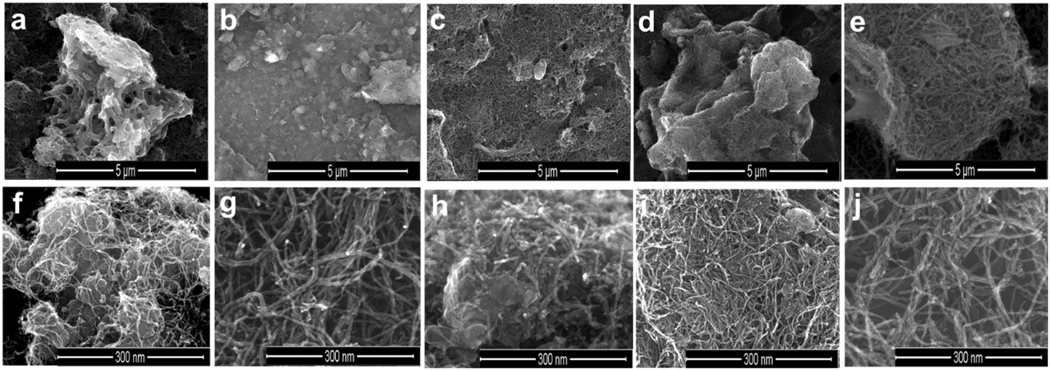 | ||
| Fig. 2 SEM images captured for (a and f) ZNT-900, (b and g) Fe-ZNT-900, (c and h) Co-ZNT-900, (d and i) Fe1Co1-ZNT-900 and (e and j) Fe1Co2-ZNT-900 catalysts at different resolutions. | ||
At lower magnifications (Fig. 2a–e), a hollow sponge-like structure of the ZNT-900 catalyst can be seen, whereas other transition-metal-doped ZIF-8@CNT catalysts contained a highly dense crystal structure of the catalysts, which was probably due to the presence of a micro-/mesopore combination. SEM–EDX mapping was performed to analyse the elemental composition of the as-prepared ZIF-8@CNT catalysts. The results revealed that all the catalysts consisted of similar amounts of carbon (Table 2) evenly distributed over the surface, which was as expected for the carbon-based catalysts (Fig. S3†). The surface metal concentrations disclosed by the SEM–EDX mapping and microwave plasma-atomic emission spectroscopy (MP-AES) analysis overlap with each other, showing a good incorporation of desired metal contents in the catalyst materials (Table 2). High-temperature annealing at 900 °C has been reported to effectively remove Zn traces from the material and the same was observed with our catalysts.56,57 SEM is confined to lower magnifications and does not provide an in-depth picture of the material. Therefore, STEM measurements were performed on all the catalyst materials at different resolutions. Bright-field (BF) STEM images for bimetallic ZIF-8@CNT catalysts (Fig. 3) confirm the homogenously wrapped ZIF 3D crystal structure with CNTs. The FeCo alloys can be clearly seen as dark dots in Fig. 3 in the images with different magnifications. It can be inferred that the dopants, i.e., N, O, and transition metals, were well spread over the surface and metal nanoparticles of about 5 nm diameter were encapsulated in a ZIF-8@CNT porous carbon shell (Fig. S4†). Also, the high-angle annular dark field (HAADF)-STEM images captured at lower resolutions showed a bright spot corresponding to FeCo alloys (Fig. 4).
| Catalyst | C | N | O | Fe (SEM–EDX) | Fe (MP-AES) | Co (SEM–EDX) | Co (MP-AES) |
|---|---|---|---|---|---|---|---|
| ZNT-900 | 90.42 | 6.45 | 1.96 | 0.00 | — | — | — |
| Fe-ZNT-900 | 86.11 | 4.90 | 7.16 | 1.83 | 1.994 | — | — |
| Co-ZNT-900 | 86.08 | 7.28 | 3.36 | — | — | 3.19 | 2.997 |
| Fe1Co1-ZNT-900 | 89.16 | 3.17 | 4.46 | 2.70 | 3.561 | 2.86 | 3.016 |
| Fe1Co2-ZNT-900 | 85.87 | 6.88 | 3.58 | 1.28 | 1.34 | 2.39 | 2.48 |
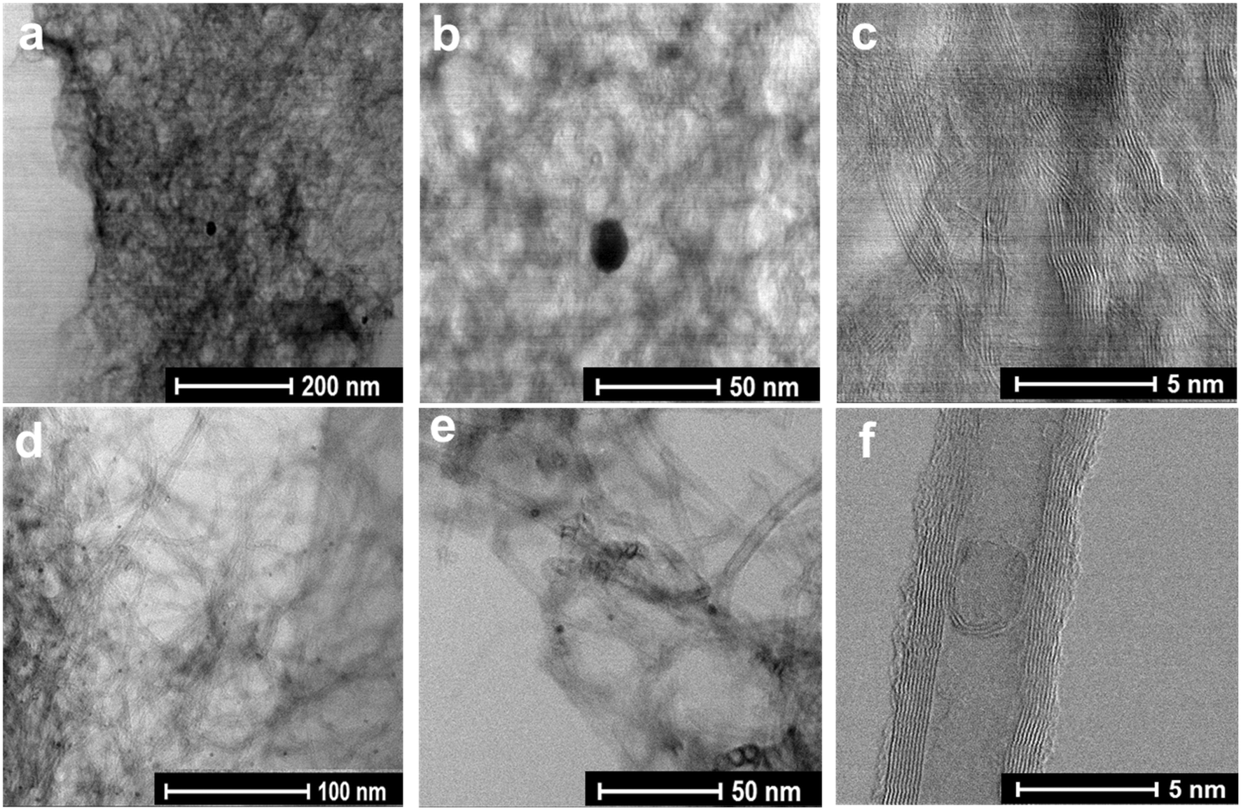 | ||
| Fig. 3 BF-STEM images for (a–c) Fe1Co1-ZNT-900 and (d–f) Fe1Co2-ZNT-900 catalysts at different resolutions. | ||
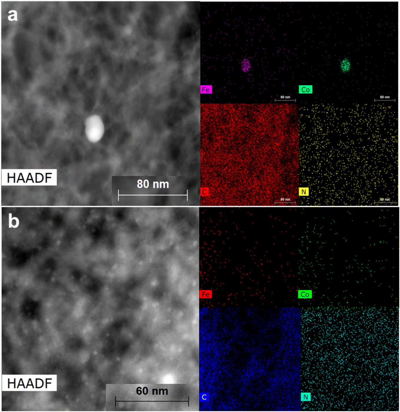 | ||
| Fig. 4 HAADF-STEM images for (a) Fe1Co1-ZNT-900 and (b) Fe1Co2-ZNT-900 catalysts with corresponding EDX mapping. | ||
To further confirm the bonding configuration of the elements, X-ray photoelectron spectroscopy (XPS) analysis was performed. A comparative XPS survey spectrum recorded from 1000 to 200 eV for all the catalysts indicates the presence of different elements, i.e. C, N, O, Fe and Co, as shown in Fig. S5.† To identify the role of chemical entities, high-resolution XPS was carried out in the N 1s region (Fig. 5) and Fe 2p and Co 2p regions (Fig. S6†). A variety of nitrogen-bonded moieties were present in all the ZIF-8@CNT catalyst materials, namely, pyridinic-N (∼398 eV), pyrrolic-N (∼400 eV), nitrogen-coordinated metal centres (M–Nx, ∼399 eV), imines (∼397,5 eV), graphitic-N (∼401 eV), N–H (∼403 eV), and finally oxidised nitrogen, N–O (∼404 eV). The atomic ratios of all the elements are summarised in Table S3.† Several reports and theoretical molecular orbital diagram models suggest that the N atom transfers electrons to the π* orbital of O2 (ref. 58), and pyridinic-N, pyrrolic-N, M–Nx, and graphitic-N are the most encountered ORR-active centres.59–61 Therefore, the composition of these four N types are presented in Fig. 5f. The bimetallic ZIF-8@CNT catalyst (Fe1Co1-ZNT-900 and Fe1Co2-ZNT-900) carries the highest amount of all four N species with a high amount of M–Nx centres, which promotes the electron transfer and, in turn, the ORR kinetics. The high-resolution XPS spectra in the Fe 2p region show doublets at ∼710.8 and ∼724.3 eV, reflecting the Fe 2p3/2 and Fe 2p1/2 spin–orbit coupling levels.62 The deconvoluted peaks of Fe 2p3/2 at binding energies of ∼707.1, ∼710.8 and ∼713.0 eV reflect different forms of Fe (Fe0, Fe2+, Fe3+, respectively). The peak at ∼709.6 eV reflects the presence of Fe–Nx sites.63,64 It can be seen from Fig. S5† that the Fe–Nx intensity is highest in the Fe1Co2-ZNT-900 catalyst, reflecting its highly dense M–Nx centres. The two visible broader peaks at ∼780.5 and ∼796.0 eV indicate Co 2p3/2 and Co 2p1/2, respectively. The deconvoluted peaks at ∼783.0, ∼780.5 and ∼778.2 eV indicate the presence of Co in the oxidation states of Co2+, Co3+ and zero-valent Co0, respectively.65,66 The two characteristic peaks at ∼786.3 and ∼803.8 eV represent the satellite peaks.67 No traces of Zn were observed in the XPS analysis, which is expected, as the high-temperature pyrolysis has most likely evaporated the Zn from the carbon network.
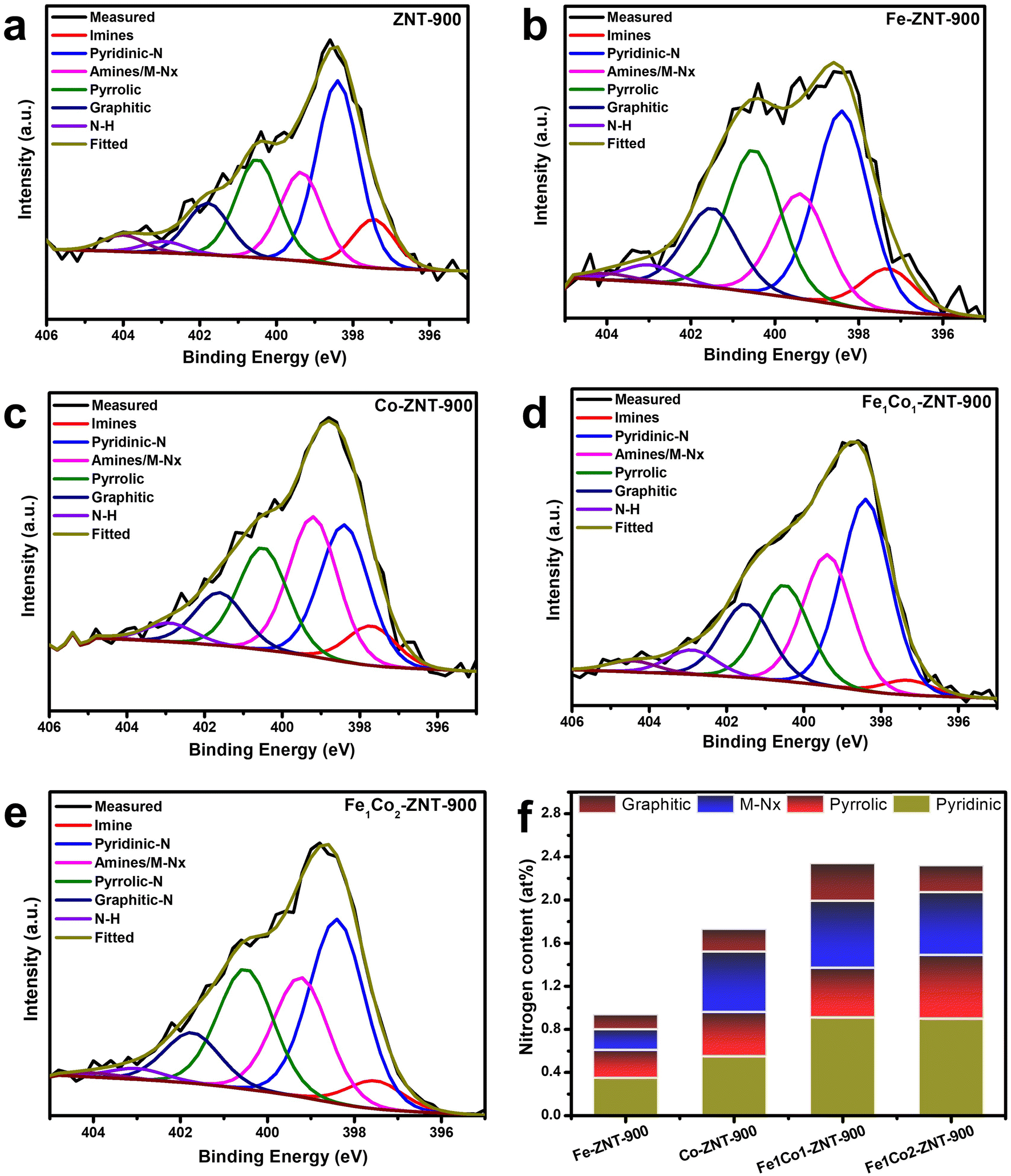 | ||
| Fig. 5 (a–e) Comparison of N 1s XPS spectra for (a) ZNT-900, (b) Fe-ZNT-900, (c) Co-ZNT-900, (d) Fe1Co1-ZNT-900 and (e) Fe1Co2-ZNT-900 catalysts and (f) N content for different nitrogen groups. | ||
2.2. Electrochemical performance of ZIF-8@CNT catalysts
A clear difference in the surface morphologies of the as-prepared ZIF-8@CNT catalysts can be observed from the results discussed in the earlier sections. These structural/morphological differences will affect the mass/charge transfer and total electrocatalytically active sites, which influence their ORR performance.68 The electrochemical performance of the ZIF-8@CNT catalysts was investigated using a rotating disk electrode (RDE) setup. The linear sweep voltammetry (LSV) and cyclic voltammetry (CV) curves obtained for all the catalysts are displayed in Fig. 6. The ZIF-8@CNT catalysts showed excellent ORR performance at a low catalyst loading (0.1 mg cm−2) in 0.1 M KOH solution (Fig. 6a). The metal-free catalyst (ZNT-900) showed the poorest ORR activity, which was expected due to its lowest BET surface area and absence of M–Nx centres. A clear influence of transition metal doping on the ORR performance can be observed in both single- and binary-metal-doped ZIF-8@CNT catalysts. Bimetallic ZIF-8@CNT catalysts (Fe1Co1-ZNT-900 and Fe1Co2-ZNT-900) showed the highest onset (at a current density j = −0.1 mA cm−2) and half-wave potentials (at j = −3.0 mA cm−2) of ∼0.995, ∼0.996 V and 0.846, 0.847 V vs. RHE, respectively, which surpass that of the commercially used Pt/C catalyst in terms of half-wave potential (E1/2 = 0.834 V). Both bimetallic ZIF-8@CNT catalysts reached similar limiting current densities (jL) of −5.92 and −5.79 mA cm−2, which is slightly lower compared to that of the Pt/C catalyst (−6.4 mA cm−2). This could be due to the well-developed micro–mesoporous structure and a high number of new active sites derived from nitrogen and Fe/Co doping (M–Nx centres). Also, the presence of FeCo particles introduces high-density active centres, which makes them more accessible to the reactants to promote the ORR kinetics.69 The ORR parameters obtained for all ZIF-8@CNT catalysts are listed in Table 3.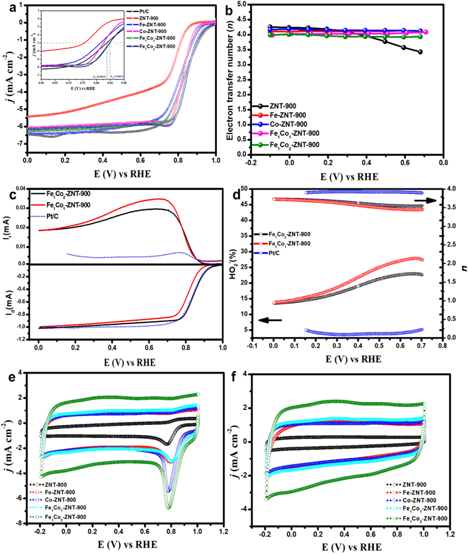 | ||
| Fig. 6 (a) ORR polarisation curves for ZIF@CNT catalysts recorded at 1900 rpm with a scan rate of 10 mV s−1 in O2-saturated 0.1 M KOH. (b) Electron transfer number (n) obtained from K–L plots for all the catalysts. (c) RRDE results for Fe1Co2-ZNT-900, Fe1Co1-ZNT-900 and Pt/C catalysts in 0.1 M KOH at 1900 rpm with a scan rate of 10 mV s−1. (d) Electron transfer number (n) and HO2− yield for Fe1Co2-ZNT-900, Fe1Co1-ZNT-900 and Pt/C catalysts. CV curves were recorded in (e) O2-saturated and (f) Ar-saturated 0.1 M KOH at 100 mV s−1. | ||
| Catalyst | E 1/2 (V) | E onset (V) | j L (mA cm−2) | E p (V) | n |
|---|---|---|---|---|---|
| ZNT-900 | 0.750 | 0.874 | −5.54 | 0.73 | 3.97 ± 0.31 |
| Fe-ZNT-900 | 0.813 | 0.944 | −6.27 | 0.79 | 4.0 ± 0.06 |
| Co-ZNT-900 | 0.825 | 0.924 | −5.93 | 0.80 | 4.05 ± 0.02 |
| Fe1Co1-ZNT-900 | 0.846 | 0.995 | −5.92 | 0.77 | 4.03 ± 0.03 |
| Fe1Co2-ZNT-900 | 0.847 | 0.996 | −5.79 | 0.78 | 3.96 ± 0.03 |
To further evaluate the electrocatalytic ORR behaviour of the catalysts, hydrodynamic voltammograms were recorded at different electrode rotation rates (ω = 360–4600 rpm) as shown in Fig. S7.† To evaluate the oxygen reduction pathway, the electron transfer number (n) was calculated from Koutecky–Levich (K–L) plots. In Fig. 6b, the number of electrons transferred during the ORR at the surface of ZIF-8@CNT catalysts is displayed and a clear influence of transition metal doping compared to the metal-free ZIF-8@CNT catalysts can be seen. The n value for ZNT-900 is 3.97 ± 0.31 and when Fe is doped the value of n reached 4.0 ± 0.06. Also, for the bimetallic ZIF-8@CNT catalysts the n value was 4.03 ± 0.03 (Fe1Co1-ZNT-900) and 3.96 ± 0.03 (Fe1Co2-ZNT-900). To further study the ORR pathway, rotating ring-disk electrode (RRDE) measurements were conducted to analyse the formation of hydrogen peroxide, which in turn were used to calculate the number of electrons transferred (n) (Fig. 6c). The collected ring (Ir) and disk currents (Id) recorded for Fe1Co2-ZNT-900, Fe1Co1-ZNT-900 and Pt/C catalysts are presented in Fig. 6c. The RRDE polarisation curve presented in Fig. 6c (bottom) clearly shows that the bimetallic catalyst (Fe1Co2-ZNT-900) outperforms the Fe1Co1-ZNT-900 and Pt/C catalysts, which follows a similar trend observed in RDE polarisation curves presented in Fig. 6a. The HO2− yield for Fe1Co2-ZNT-900 reaches a maximum of 22.5% (at E = 0.70 V) and a minimum of 13.5%, delivering an average electron transfer number (navg) of 3.73, which is more than that of the Fe1Co1-ZNT-900 catalyst (navg = 3.6) as shown in Fig. 6d. The highly micro–mesoporous morphology of mono- and bimetallic ZIF-8@CNT catalysts prevented the aggregation of metals during the electrocatalytic process via stabilising the most accessible M–Nx active sites, which in turn accelerated the electron transfer process. Therefore, due to the presence of M–Nx active centres supported by XPS analysis, the transition-metal-doped electrocatalysts delivered the highest ORR performance when compared to the metal-free ZIF-8@CNT catalyst.
Fig. 6e and f represent the CVs recorded in O2- and Ar-saturated 0.1 M KOH at the scan rate of 100 mV s−1, respectively. The ORR peak potentials (Ep) for all the catalysts are listed in Table 3. Metal-free ZIF-8@CNT catalysts showed the lowest Ep, which can be attributed to their textural properties and absence of M–Nx centres. It can be observed that introducing transition metals into the ZIF-8@CNT 3D network creates more accessible M–Nx centres that accelerate the electron transfer process.70 The Fe1Co2-ZNT-900 catalyst showed an intensive ORR peak at around 0.78 V vs. RHE due to the collective contribution of FeCo alloys and their textural properties. A similar behaviour can be seen in CV curves obtained in Ar-saturated 0.1 M KOH, with Fe1Co2-ZNT-900 and Fe1Co1-ZNT-900 catalysts carrying the highest capacitive currents in comparison to other catalysts. It is well evident that capacitive currents are highly dependent on the porosity of the catalyst material.71 Therefore, the higher capacitive currents for Fe1Co2-ZNT-900 and Fe1Co1-ZNT-900 are most likely due to their highly dense micro–mesoporous morphology with promising textural features. Based on the electrocatalytic activity of the prepared catalysts, Fe1Co2-ZNT-900 and Fe1Co1-ZNT-900 catalysts showed the maximum ORR application potential in terms of half-wave potential, onset potential, and their highly porous 3D ZIF structure with the presence of active N-centers and high number of M–Nx sites promoting the 4e− ORR pathway. Therefore, these two catalysts were selected for further evaluation under the AEMFC conditions.
2.3. AEMFC performance
The AEMFC testing was performed with Pt–Ru/C and FeCo-ZNT-900 (Fe:Co = 1:1 and 1:2) catalysts used at the anode and cathode, respectively. An open circuit voltage (OCV) of 1.0, 1.03, and 1.01 V was recorded for Fe1Co1-ZNT-900-, Fe1Co2-ZNT-900-, and Pt/C-coated cathodes, respectively, as shown in the j–V polarisation curves (Fig. 7a). This indicates the better intrinsic electrocatalytic activity of these FeCo-based catalysts which in turn is accredited to the highly accessible active centres.72 The power density curves shown in Fig. 7b indicate that the Fe1Co2-ZNT-900 catalyst performs better than Fe1Co1-ZNT-900 with a maximum power density (Pmax) of 0.171 W cm−2, which is comparable to that of the commercial Pt/C catalyst (0.215 W cm−2). Moreover, the current density of the Fe1Co2-ZNT-900 catalyst at 0.5 V (j0.5) was 0.326 A cm−2, which is comparable to the that of the Pt/C catalyst (j0.5 = 0.359 A cm−2). Also, it is evident from the RRDE results that the Fe1Co2-ZNT-900 catalyst showed about 17.6% lower HO2− yield when compared to the Fe1Co1-ZNT-900 catalyst, which affects the overall ORR kinetics and pathway that is reflected by the better AEMFC performance of the Fe1Co2-ZNT-900 catalyst. Most importantly, in the voltage range considered suitable for practical AEMFC use (between 0.8 and 0.6 V),73,74 Fe1Co2-ZNT-900 outperforms the Pt/C cathode. This is ascribed to the effective mass transport of reactants at the active sites in the electrodes due to the hierarchical porous texture in the catalyst materials. It should be noted that the ORR performance of the catalysts evaluated from RDE does not provide a realistic picture when their activity in the fuel cell is taken into consideration.75 The probable reasons for such discrepancies can be ascribed to varying operational conditions in fuel cells such as mass transport, operational temperature, water transfer regulations, most importantly the insufficient ionic conductivity of AEM, etc. Recent reports suggest that the adjustment of the catalyst layer with the ionomer and AEM plays a vital role in generating promising power densities.74,76 Therefore, the ORR activity of the catalysts in 0.1 M KOH solution and their corresponding AEMFC performance are not comparable. In previous studies, we have tested Fe- and Co-based catalysts in an AEMFC using a 10 μm thick Aemion+ AEM, but no reports are available with the Aemion+® 15 μm AEM.38,75,77–80 The Aemion+ AEM (10 μm) consists of repeating units of methylated polybenzimidazoles, which offers high stability in AEMFCs by employing the steric-crowding strategy to stabilise the C-2 position of the imidazole group.81 Also, the thickness of the AEM plays a crucial role in the efficient migration of OH− ions and H2O molecules.82 Wei et al. demonstrated that the higher thickness of the Aemion+ AEM (25 μm) exhibits lower AEMFC performance by achieving 23.5% lower Pmax in comparison to 10 μm Aemion AEM.83 A thinner AEM provides better water back-diffusion from the membrane, resulting in more favourable water management. In addition to membrane thickness, the ion exchange capacity (IEC) also affects the AEMFC performance. An AEM with higher thickness possesses lower IEC, which as a result increases OH− ionic resistance and lowers fuel cell performance.84 Aemion+ (10 μm) exhibits a higher IEC of 3.0 mmol g−1, which is 33.3% more than for the Aemion+ (15 μm) AEM, resulting in higher ionic resistance in the case of Aemion+® 15 μm.85 The latter can be observed by considerably lower power output in the case of Aemion+® 15 μm in comparison with previously reported Aemion+ AEMs having a thickness of 10 μm. Despite the similar building blocks in Aemion+ and Aemion+® 15 μm, the noticeable variation in their physical and chemical properties resulted in the performance difference in AEMFC. The peak power densities obtained for FeCo-based catalysts in this work are not very high as compared to those of similar catalyst materials reported in the literature. In fact, considering all the influencing factors in AEMFC operation and especially the AEM, the catalysts performed quite well in fuel cell conditions and further optimisation is being conducted to achieve higher power densities.
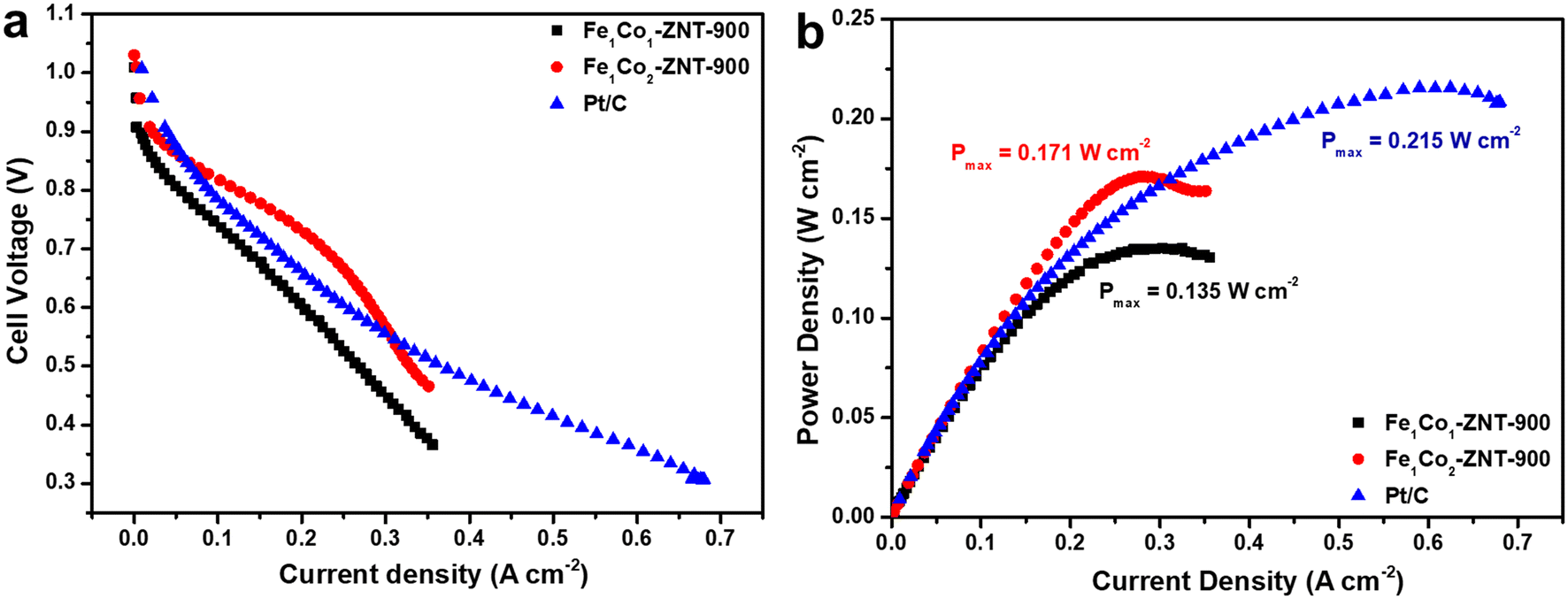 | ||
| Fig. 7 (a) Polarisation and (b) power density curves obtained for Fe1Co1-ZNT-900, Fe1Co2-ZNT-900, and Pt/C cathode catalysts in H2/O2 AEMFCs [anode catalyst: PtRu/C. AEM: Aemion+® 15 μm. T = 65 °C]. | ||
3. Conclusions
Metal-free and transition-metal-doped ZIF-8@CNT catalysts were prepared by one-step high-temperature pyrolysis at 900 °C. The existence of M–Nx sites was shown by XPS analysis and XRD analysis showed the presence of pure Fe and Co nanoparticles and FeCo nanoalloys with a minimal existence of Fe3O4 nanoparticles. The presence of alloys was further confirmed by using STEM measurements. All the transition-metal-doped ZIF-8@CNT catalysts showed good ORR activity, with metal-free ZNT-900 being the poorer-performing electrocatalyst among the tested ones. The ZIF-8@CNT catalysts showed excellent electrocatalytic ORR activity in 0.1 M KOH at a low catalyst loading of 0.1 mg cm−2. Bimetallic ZIF-8@CNT electrocatalysts (Fe1Co2-ZNT-900) delivered the highest half-wave and onset potential of 0.847 and 0.996 V vs. RHE, respectively, and outperformed the Pt/C catalyst in terms of half-wave potential (0.834 V). The performance of bimetallic ZIF-8@CNT electrocatalysts was investigated in AEMFCs, and the Fe1Co2-ZNT-900 cathode reached a Pmax of 0.171 W cm−2, which was close to the Pmax achieved with the Pt/C catalyst. The AEMFC results can be improved by further optimising various factors, such as the AEM, operational temperature, water management, etc. All in all, the bimetallic ZIF-8@CNT catalysts performed quite well in AEMFCs and the results were comparable to those of similar materials and these catalysts should be explored more in-depth to achieve more promising results in AEM fuel cells.4. Experimental section
4.1. Chemicals
Commercially available zeolitic imidazolate framework-8 (ZIF-8) (Basolite® Z1200, Sigma-Aldrich), multiwalled carbon nanotubes (MWCNTs, NC3150, ≥95%, Nanocyl S.A.), cobalt(II) acetate (Co(OAc)2, 98%, Alfa Aesar), iron(II) acetate (Fe(OAc)2, 95%, Sigma-Aldrich), Nafion solution (5 wt% in lower aliphatic alcohols, Sigma-Aldrich), 2-propanol (Honeywell), methanol (MeOH, 99.99%, Lach-Ner), and potassium hydroxide (KOH, ≥85%, Sigma-Aldrich) were used without further purification. Milli-Q water was used to prepare the solutions.4.2. Synthesis of ZIF-8@CNT catalysts
The catalyst materials were prepared by adding different proportions of Fe and Co salts with a fixed amount of ZIF-8 and MWCNTs as summarised in Table S1.† First, a catalyst without metal addition was prepared by mixing 105 mg of ZIF-8 and 100 mg of MWCNTs in 40 mL MeOH solvent and named ZNT-900 after the pyrolysis of the dried mixture. Fe-doped catalyst was prepared by mixing 8.2 mg of Fe(OAc)2, 100 mg of MWCNTs, and 105 mg of ZIF-8 in MeOH. The amount of Fe was 2.5 wt% of MWCNTs and was selected from the procedure mentioned by Ratso et al.86 Similarly, all other catalyst dispersions were prepared and sonicated (Branson 1510E-MTH; power output = 70 W, frequency = 40 kHz, Bransonic) for about 1.5–2 h to obtain a homogenous slurry followed by oven-drying at 60 °C overnight. The blackish powder obtained after drying was then pyrolysed at 900 °C for 2 h at a ramp rate of 10 °C min−1 in an inert atmosphere maintained by the continuous supply of N2 gas throughout the pyrolysis tube (N2, 99.99%, Linde Gas). In all, five different catalysts were prepared and were named as ZNT-900, Fe-ZNT-900, Co-ZNT-900, Fe1Co2-ZNT-900 (Fe:Co = 1:2), and Fe1Co1-ZNT-900 (Fe:Co = 1:1). If not stated otherwise, Z stands for ZIF-8, NT for MWCNTs and 900 represents the pyrolysis temperature of 900 °C.
4.3. Physicochemical characterisation of ZIF-8@CNT catalysts
The morphology of the catalyst materials was examined by high-resolution scanning electron microscopy (HR-SEM, Helios NanoLab 600, FEI Company) at 20 kV and scanning transmission electron microscopy (STEM, Titan Themis 200 (FEI) (S)TEM) at 200 kV. An energy-dispersive X-ray (EDX) spectrometer combined with SEM and STEM instruments (INCA Energy 350, Oxford Instruments, Abingdon, UK, and Super-X EDX, FEI/Bruker, respectively) was used to analyse the elemental composition of the catalyst materials. An X-ray diffractometer (XRD, Bruker D8 Advance), supplied with Cu Kα as a radiation source and a LynxEye line detector, and an X-ray photoelectron spectrometer (XPS, Scienta SES-100 electron analyser using Mg Kα radiation from a Thermo XR3E2 X-ray source) were used to study the crystalline structure and surface chemical composition of the catalyst materials, respectively. The specific surface area (SBET) and porosity measurements were calculated using the Brunauer–Emmett–Teller (BET) model and N2 adsorption–desorption isotherms, respectively. The total pore volume (Vtot) was measured at a N2 saturation pressure (P/P0) of 0.97. The pore size distribution (PSD) was estimated from N2 isotherms using a quenched solid density functional theory (QSDFT) equilibrium model for slit-type pores. Micro-Raman spectra were recorded in back-scattering geometry on an inVia Renishaw spectrometer in conjunction with a confocal microscope (Leica Microsystems CMS GmbH, 50× objective) and an argon ion laser operated at 514.5 nm. Low incident laser power density at the sample prevented excessive sample heating and/or decomposition. The metal contents in the catalyst materials were analysed by microwave plasma atomic emission spectroscopy (MP-AES) using an Agilent 4210 MP-AES instrument.4.4. Electrochemical studies of ZIF-8@CNT catalysts
All the electrochemical measurements were performed on catalyst-coated glassy carbon (GC) disks (GC-20SS, Tokai Carbon Ltd., Japan). The GC disks inserted into a Teflon holder were used as electrode substrates for ORR studies. To clean the GC surface, it was polished using P1200 SiC abrasive paper and 1 and 0.3 μm alumina slurries (Buehler, USA) until a shiny and reflective mirror-like appearance was observed. The GC electrodes were further cleaned via sonication in Milli-Q water and 2-propanol for 5 min in each solvent. The catalyst ink was prepared by suspending 8 mg of the catalyst powder in 2 mL of 2-propanol and 10 μL of 5 wt% Nafion ionomer solution followed by sonication until a homogenous suspension was obtained. A certain aliquot (1.7 μL) of the catalyst suspension was pipetted onto the GC surface and allowed to dry in air. A total of 5 μL catalyst ink was deposited on the pre-polished GC surface to obtain a catalyst loading of 0.1 mg cm−2.A standard round-shaped five-neck glass cell (volume = 100 mL) with a three-electrode configuration was used to measure the electrochemical performance of the as-prepared ZIF-8@CNT catalysts in 0.1 M KOH electrolyte solution (pH ∼13) using an Autolab potentiostat/galvanostat PGSTAT128N (Metrohm Autolab, the Netherlands). The catalyst-coated GC electrode, saturated calomel electrode (SCE), and a carbon rod were used as the working, reference, and counter electrode, respectively. The electrode rotation rate (ω = 360–4600 rpm) was controlled using an EDI101 rotator and CTV101 speed control unit (Radiometer). Rotating disk electrode (RDE) voltammetry and cyclic voltammetry (CV) curves were recorded in the potential window of −1.2 to 0.0 V (vs. SCE) at a scan rate (ν) of 10 mV s−1; later, the recorded potentials were converted into potential values vs. reversible hydrogen electrode (RHE) using the equation ERHE = ESCE + 0.241 + 0.059 × pH.87 A commercial Pt/C (20 wt% Pt) catalyst was used for comparing the electrochemical performance of the as-prepared ZIF-8@CNT catalysts. All the RDE voltammetry curves were IR-compensated using ohmic resistance values obtained with electrochemical impedance spectroscopy. If not stated otherwise, all the electrochemical experiments were conducted in O2- or Ar-saturated (99.999%, Linde) 0.1 M KOH electrolyte. To evaluate the ORR pathway, electron transfer number (n) was calculated from Koutecky–Levich (K–L) plots using eqn (1)–(3).39,88
| j−1 = jk−1 + B−1ω1/2 | (1) |
| jk = nFkCO | (2) |
| B = 0.62 nFCO(DO)2/3v−1/6 | (3) |
485 C mol−1), DO is the O2 diffusion coefficient in 0.1 M KOH (1.9 × 10⁻⁵ cm2 s−1), ν is the kinematic viscosity of the electrolyte solution (0.01 cm2 s−1), CO is the concentration of O2 in the bulk solution (1.2 × 10⁻⁶ mol cm−3) and ω is the electrode rotation rate (rad s−1).89
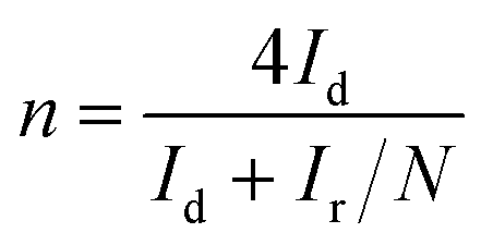
To further investigate the ORR pathway, the rotating ring-disk electrode (RRDE) measurements were conducted using an MSRX speed controller and an AFMSRX rotator (Pine Research, USA) to evaluate the hydroperoxide anion (HO2−) yield (%) and the number of electrons transferred (n).90 A fixed-disk RRDE tip composed of a GC disc-Pt ring was attached to the AFMSRX rotator. The GC projected a geometric surface area of 0.164 cm2 with a catalyst loading of 0.1 mg cm−2. The catalyst inks were prepared similarly to RDE measurements. The experimental data were recorded using General Purpose Electrochemical System (GPES) software. The % HO2− and n values were calculated using eqn (4) and (5), respectively.
 | (4) |
 | (5) |
The detection of HO2− was measured using a Pt ring electrode with a collection efficiency (N) of 0.25 at an applied potential of 1.55 V vs. RHE. The Pt ring was activated before use by running at least three potential cycles within a 0.05–1.55 V (vs. RHE) window at the electrode rotation rate of 1900 rpm with a scan rate of 100 mV s−1.
4.5. MEA preparation and AEMFC tests
The membrane–electrode assembly (MEA) was prepared by sandwiching ZIF-8@CNT catalyst-coated gas diffusion layer (GDL, Sigracet 39 BB) with Aemion+® 15 μm (AF2-HLF8-15-X, 15 μm thickness, Ionomr Innovations, Canada) anion-exchange membrane (AEM) as shown in Fig. S1.† Cathode inks were prepared by dispersing 12.5 mg of FeCo-ZNT-900 in 1350 μL of methanol, 390 μL of Milli-Q water and 130 μL of 3 wt% ionomer solution prepared via dissolving Aemion+ powder (AP2-INN8-00-X) (Ionomr Innovations, Inc.) in methanol. The catalyst ink for the anode was prepared by dispersing 6.67 mg of Pt–Ru/C (50:25:25, Alfa Aesar), 690 μL of methanol, 196 μL of Milli-Q water, and 49 μL of 3 wt% same ionomer solution. The homogeneously dispersed ink was obtained by sonication of the suspensions under an ice bath for about 90 min. Both the prepared anode and cathode inks were incrementally deposited onto the gas diffusion layers until a loading of 0.8 mgPt–Ru cm−2 and 2 mg cm−2, respectively, were achieved. To ensure sufficient ion exchange, the as-prepared electrodes and anion-exchange membrane were soaked in 3 M KOH solution for 24 and 96 h, respectively, prior to assembling the AEMFC setup. The 3 M KOH solution was frequently replenished every 24 h. The pretreated AEM, electrodes, and silicone gaskets were fixed in a single-cell fixture (Fuel Cell Technologies Inc., USA) of 5 cm2 active area at 9 Nm torque. Single-cell AEMFC experiments were conducted using a Greenlight fuel cell test station (G40 Fuel Cell System, Hydrogenics, Canada) by feeding 65% humidified H2 and O2 gases at a flow rate of 1 NLPM at a backpressure of 0.2 MPa; the cell temperature was held at 65 °C.
Conflicts of interest
The authors declare no conflict of interest.Acknowledgements
The present work was financially supported by the Estonian Research Council (grants PRG723, PRG4 and PRG1509). This research was also supported by the EU through the European Regional Development Fund (TK141, “Advanced materials and high-technology devices for energy recuperation systems”; TK134, “Emerging orders in quantum and nanomaterials” and TK143 “Molecular Cell Engineering”). This study was also supported by the European Commission INTERREG research funding (MLTKT22537I, “Improving quality of BSR waters by advanced treatment processes”).References
- P. J. Megía, A. J. Vizcaíno, J. A. Calles and A. Carrero, Hydrogen production technologies: from fossil fuels toward renewable sources, A mini review, Energy Fuels, 2021, 35, 16403–16415 CrossRef.
- H. Nazir, C. Louis, S. Jose, J. Prakash, N. Muthuswamy, M. E. M. Buan, C. Flox, S. Chavan, X. Shi, P. Kauranen, T. Kallio, G. Maia, K. Tammeveski, N. Lymperopoulos, E. Carcadea, E. Veziroglu, A. Iranzo and A. M. Kannan, Is the H2 economy realizable in the foreseeable future? Part I: H2 production methods, Int. J. Hydrogen Energy, 2020, 45, 13777–13788 CrossRef CAS.
- H. Nazir, N. Muthuswamy, C. Louis, S. Jose, J. Prakash, M. E. M. Buan, C. Flox, S. Chavan, X. Shi, P. Kauranen, T. Kallio, G. Maia, K. Tammeveski, N. Lymperopoulos, E. Carcadea, E. Veziroglu, A. Iranzo and A. M. Kannan, Is the H2 economy realizable in the foreseeable future? Part III: H2 usage technologies, applications, and challenges and opportunities, Int. J. Hydrogen Energy, 2020, 45, 28217–28239 CrossRef CAS.
- I. Staffell, D. Scamman, A. V. Abad, P. Balcombe, P. E. Dodds, P. Ekins, N. Shah and K. R. Ward, The role of hydrogen and fuel cells in the global energy system, Energy Environ. Sci., 2019, 12, 463–491 RSC.
- L. Elbaz, M. Shao, J. Shui and C. Santoro, Introduction to the themed issue on frontiers of hydrogen energy and fuel cells, Ind. Chem. Mater., 2023, 1, 280–281 RSC.
- M. M. Hossen, M. S. Hasan, M. R. I. Sardar, J. B. Haider, Mottakin, K. Tammeveski and P. Atanassov, State-of-the-art and developmental trends in platinum group metal-free cathode catalyst for anion exchange membrane fuel cell (AEMFC), Appl. Catal., B, 2023, 325, 121733 CrossRef CAS.
- R. Ma, G. Lin, Y. Zhou, Q. Liu, T. Zhang, G. Shan, M. Yang and J. Wang, A review of oxygen reduction mechanisms for metal-free carbon-based electrocatalysts, npj Comput. Mater., 2019, 5, 78 CrossRef.
- Y. Hong, L. Li, B. Huang, X. Tang, W. Zhai, T. Hu, K. Yuan and Y. Chen, Molecular control of carbon-based oxygen reduction electrocatalysts through metal macrocyclic complexes functionalization, Adv. Energy Mater., 2021, 11, 2100866 CrossRef CAS.
- X. Zhao and K. Sasaki, Advanced Pt-based core–shell electrocatalysts for fuel cell cathodes, Acc. Chem. Res., 2022, 55, 1226–1236 CrossRef CAS PubMed.
- S. Hussain, H. Erikson, N. Kongi, A. Sarapuu, J. Solla-Gullón, G. Maia, A. M. Kannan, N. Alonso-Vante and K. Tammeveski, Oxygen reduction reaction on nanostructured Pt-based electrocatalysts: A review, Int. J. Hydrogen Energy, 2020, 45, 31775–31797 CrossRef CAS.
- L. Osmieri, L. Pezzolato and S. Specchia, Recent trends on the application of PGM-free catalysts at the cathode of anion exchange membrane fuel cells, Curr. Opin. Electrochem., 2018, 9, 240–256 CrossRef CAS.
- J. Zhang, W. Zhu, T. Huang, Y. Pei, G. Shen, Z. Nie, D. Xiao, Y. Yin and M. D. Guiver, Recent insights on catalyst layers for anion exchange membrane fuel cells, Adv. Sci., 2021, 8, 2100284 CrossRef CAS PubMed.
- B. Ricciardi, B. Mecheri, W. da Silva Freitas, V. C. Ficca, E. Placidi, I. Gatto, A. Carbone, A. Capasso and A. D'Epifanio, Porous iron-nitrogen-carbon electrocatalysts for anion exchange membrane fuel cells (AEMFC), ChemElectroChem, 2023, 10, e202201115 CrossRef CAS.
- A. Sarapuu, E. Kibena-Põldsepp, M. Borghei and K. Tammeveski, Electrocatalysis of oxygen reduction on heteroatom-doped nanocarbons and transition metal–nitrogen–carbon catalysts for alkaline membrane fuel cells, J. Mater. Chem. A, 2018, 6, 776–804 RSC.
- H. Adabi, A. Shakouri, N. Ul Hassan, J. R. Varcoe, B. Zulevi, A. Serov, J. R. Regalbuto and W. E. Mustain, High-performing commercial Fe–N–C cathode electrocatalyst for anion-exchange membrane fuel cells, Nat. Energy, 2021, 6, 834–843 CrossRef CAS.
- R. Gutru, Z. Turtayeva, F. Xu, G. Maranzana, R. Thimmappa, M. Mamlouk, A. Desforges and B. Vigolo, Recent progress in heteroatom doped carbon based electrocatalysts for oxygen reduction reaction in anion exchange membrane fuel cells, Int. J. Hydrogen Energy, 2023, 48, 3593–3631 CrossRef CAS.
- K. Kusada, D. Wu and H. Kitagawa, New aspects of platinum group metal-based solid-solution alloy nanoparticles: binary to high-entropy alloys, Chem. – Eur. J., 2020, 26, 5105–5130 CrossRef CAS PubMed.
- W. Xu, D. Yoon, Y. Yang, Y. Xiong, H. Li, R. Zeng, D. A. Muller and H. D. Abruña, MOF-derived bimetallic Pd–Co alkaline ORR electrocatalysts, ACS Appl. Mater. Interfaces, 2022, 14, 44735–44744 CrossRef CAS PubMed.
- G.-S. Kang, J.-H. Jang, S.-Y. Son, C.-H. Lee, Y.-K. Lee, D. C. Lee, S. J. Yoo, S. Lee and H.-I. Joh, Fe-based non-noble metal catalysts with dual active sites of nanosized metal carbide and single-atomic species for oxygen reduction reaction, J. Mater. Chem. A, 2020, 8, 22379–22388 RSC.
- H. Xu, D. Wang, P. Yang, A. Liu, R. Li, Y. Li, L. Xiao, X. Ren, J. Zhang and M. An, Atomically dispersed M–N–C catalysts for the oxygen reduction reaction, J. Mater. Chem. A, 2020, 8, 23187–23201 RSC.
- F. Tan, W. Li, J. Wang, C. Min, Z. Li, B. Zhang, X. Zheng, L. Li, L. Zhang, L. Zhou, Q. Shi and X. Yang, Clarifying the critical roles of iron in boosting oxygen reduction: Single Fe atoms anchored on carbon vacancies as efficient active sites, Appl. Catal., B, 2022, 305, 121035 CrossRef CAS.
- R. Jiang, L. Li, T. Sheng, G. Hu, Y. Chen and L. Wang, Edge-site engineering of atomically dispersed Fe–N4 by selective C–N bond cleavage for enhanced oxygen reduction reaction activities, J. Am. Chem. Soc., 2018, 140, 11594–11598 CrossRef CAS PubMed.
- G. Chen, P. Liu, Z. Liao, F. Sun, Y. He, H. Zhong, T. Zhang, E. Zschech, M. Chen, G. Wu, J. Zhang and X. Feng, Zinc-mediated template synthesis of Fe-N-C electrocatalysts with densely accessible Fe-Nx active sites for efficient oxygen reduction, Adv. Mater., 2020, 32, 1907399 CrossRef CAS PubMed.
- Y.-P. Ku, K. Ehelebe, A. Hutzler, M. Bierling, T. Böhm, A. Zitolo, M. Vorokhta, N. Bibent, F. D. Speck, D. Seeberger, I. Khalakhan, K. J. J. Mayrhofer, S. Thiele, F. Jaouen and S. Cherevko, Oxygen reduction reaction in alkaline media causes iron leaching from Fe–N–C electrocatalysts, J. Am. Chem. Soc., 2022, 144, 9753–9763 CrossRef CAS PubMed.
- L. S. Bezerra, M. Mooste, G. V. Fortunato, E. S. F. Cardoso, M. R. V. Lanza, K. Tammeveski and G. Maia, Tuning NiCo2O4 bifunctionality with nitrogen-doped graphene nanoribbons in oxygen electrocatalysis for zinc-air battery application, J. Electroanal. Chem., 2023, 928, 117000 CrossRef CAS.
- Z. Ahmed, P. K. Sachdeva, R. Rai, R. Kumar, T. Maruyama, C. Bera and V. Bagchi, Promoting Electrocatalytic Oxygen reduction in a model composite using selective metal ions, ACS Appl. Energy Mater., 2020, 3, 3645–3652 CrossRef CAS.
- T. Tang, Y. Wang, J. Han, Q. Zhang, X. Bai, X. Niu, Z. Wang and J. Guan, Dual-atom Co-Fe catalysts for oxygen reduction reaction, Chin. J. Catal., 2023, 46, 48–55 CrossRef CAS.
- M. A. Sayeed and A. P. O'Mullane, Electrodeposition at highly negative potentials of an iron-cobalt oxide catalyst for use in electrochemical water splitting, ChemPhysChem, 2019, 20, 3112–3119 CrossRef CAS PubMed.
- X. Dong, P. Sun, J. Wu, S. Huang, X. Zeng, S. Wang, X. Chen and D. Cao, MOF-derived nitrogen-doped porous carbon (NPC) supported CoFe2O4 nanoparticle composites for high-performance zinc-air batteries, Adv. Compos. Hybrid Mater., 2023, 6, 72 CrossRef CAS.
- J. Lilloja, E. Kibena-Põldsepp, A. Sarapuu, J. C. Douglin, M. Käärik, J. Kozlova, P. Paiste, A. Kikas, J. Aruväli, J. Leis, V. Sammelselg, D. R. Dekel and K. Tammeveski, Transition-metal- and nitrogen-doped carbide-derived carbon/carbon nanotube composites as cathode catalysts for anion-exchange membrane fuel cells, ACS Catal., 2021, 11, 1920–1931 CrossRef CAS PubMed.
- S. Huang, Z. Qiao, P. Sun, K. Qiao, K. Pei, L. Yang, H. Xu, S. Wang, Y. Huang, Y. Yan and D. Cao, The strain induced synergistic catalysis of FeN4 and MnN3 dual-site catalysts for oxygen reduction in proton- /anion- exchange membrane fuel cells, Appl. Catal., B, 2022, 317, 121770 CrossRef CAS.
- Y. Zhang, X. Zheng, X. Guo, J. Zhang, A. Yuan, Y. Du and F. Gao, Design of modified MOFs electrocatalysts for water splitting: High current density operation and long-term stability, Appl. Catal., B, 2023, 336, 122891 CrossRef CAS.
- D. Rani, A. Singh, R. Ladhi, L. Singla, A. R. Choudhury, K. K. Bhasin, C. Bera and M. Singh, Nanochannel mediated electrical and photoconductivity of metal organic nanotubes, ACS Sustainable Chem. Eng., 2022, 10, 6981–6987 CrossRef CAS.
- C. Wang, J. Kim, M. Kim, H. Lim, M. Zhang, J. You, J.-H. Yun, Y. Bando, J. Li and Y. Yamauchi, Nanoarchitectured metal–organic framework-derived hollow carbon nanofiber filters for advanced oxidation processes, J. Mater. Chem. A, 2019, 7, 13743–13750 RSC.
- Y. Xiong, Y. Yang, F. J. DiSalvo and H. D. Abruña, Metal–Organic-Framework-Derived Co–Fe Bimetallic oxygen reduction electrocatalysts for alkaline fuel cells, J. Am. Chem. Soc., 2019, 141, 10744–10750 CrossRef CAS PubMed.
- Z. Yang, Y. Chen, S. Zhang and J. Zhang, Identification and understanding of active sites of non-noble iron-nitrogen-carbon catalysts for oxygen reduction electrocatalysis, Adv. Funct. Mater., 2023, 2215185 CrossRef CAS.
- S. Ratso, M. T. Sougrati, M. Käärik, M. Merisalu, M. Rähn, V. Kisand, A. Kikas, P. Paiste, J. Leis, V. Sammelselg, F. Jaouen and K. Tammeveski, Effect of ball-milling on the oxygen reduction Reaction activity of iron and nitrogen co-doped carbide-derived carbon catalysts in acid media, ACS Appl. Energy Mater., 2019, 2, 7952–7962 CrossRef CAS.
- J. Lilloja, E. Kibena-Põldsepp, A. Sarapuu, A. Konovalova, M. Käärik, J. Kozlova, P. Paiste, A. Kikas, A. Treshchalov, J. Aruväli, A. Zitolo, J. Leis, A. Tamm, V. Kisand, S. Holdcroft and K. Tammeveski, Transition-metal and nitrogen-doped carbon nanotube/graphene composites as cathode catalysts for anion-exchange membrane fuel cells, ACS Appl. Energy Mater., 2023, 6, 5519–5529 CrossRef CAS.
- K. Kisand, A. Sarapuu, J. C. Douglin, A. Kikas, A. Treshchalov, M. Käärik, H.-M. Piirsoo, P. Paiste, J. Aruväli, J. Leis, V. Kisand, A. Tamm, D. R. Dekel and K. Tammeveski, Templated nitrogen-, iron-, and cobalt-doped mesoporous nanocarbon derived from an alkylresorcinol mixture for anion-exchange membrane fuel cell application, ACS Catal., 2022, 12, 14050–14061 CrossRef CAS.
- D. Seeberger, P. Hauenstein, A. Hartert and S. Thiele, The influence of the anion exchange membrane on mass-transport limiting phenomena in bipolar interface fuel cells with Fe–N/C based cathode catalyst layers, RSC Adv., 2021, 11, 31477–31486 RSC.
- J. Lilloja, M. Mooste, E. Kibena-Põldsepp, A. Sarapuu, A. Kikas, V. Kisand, M. Käärik, J. Kozlova, A. Treshchalov, P. Paiste, J. Aruvali, J. Lies, A. Tamm, S. Holdcroft and K. Tammeveski, Cobalt-, iron-and nitrogen-containing ordered mesoporous carbon-based catalysts for anion-exchange membrane fuel cell cathode, Electrochim. Acta, 2023, 439, 141676 CrossRef CAS.
- Z. Cui and X. Bai, Highly active and stable Fe/Co/N Co-doped carbon-anchored Pd nanoparticles for oxygen reduction reaction, ACS Appl. Mater. Interfaces, 2022, 14, 9024–9035 CrossRef CAS PubMed.
- R. Dawn, M. Zzaman, F. Faizal, C. Kiran, A. Kumari, R. Shahid, C. Panatarani, I. Joni, V. Verma and S. Sahoo, Origin of magnetization in silica-coated Fe3O4 nanoparticles revealed by soft X-ray magnetic circular dichroism, Braz. J. Phys., 2022, 52, 99 CrossRef CAS.
- G. A. Jacob, S. Sellaiyan, A. Uedono and R. J. Joseyphus, Magnetic properties of metastable bcc phase in Fe 64 Ni 36 alloy synthesized through polyol process, Appl. Phys. A: Mater. Sci. Process., 2020, 126, 1–7 CrossRef.
- P. Rajesh, S. Sellaiyan, A. Uedono, T. Arun and R. J. Joseyphus, Positron annihilation studies on chemically synthesized FeCo alloy, Sci. Rep., 2018, 8, 9764 CrossRef CAS PubMed.
- W.-W. Liu and A. Aziz, Review on the effects of electrochemical exfoliation parameters on the yield of graphene oxide, ACS Omega, 2022, 7, 33719–33731 CrossRef CAS PubMed.
- C. C. Zhang, S. Hartlaub, I. Petrovic and B. Yilmaz, Raman spectroscopy characterization of amorphous coke generated in industrial processes, ACS Omega, 2022, 7, 2565–2570 CrossRef CAS PubMed.
- G. Daniel, T. Kosmala, M. C. Dalconi, L. Nodari, D. Badocco, P. Pastore, A. Lorenzetti, G. Granozzi and C. Durante, Upcycling of polyurethane into iron-nitrogen-carbon electrocatalysts active for oxygen reduction reaction, Electrochim. Acta, 2020, 362, 137200 CrossRef CAS.
- M. S. Dresselhaus, G. Dresselhaus, R. Saito and A. Jorio, Raman spectroscopy of carbon nanotubes, Phys. Rep., 2005, 409, 47–99 CrossRef.
- Z. Li, L. Deng, I. A. Kinloch and R. J. Young, Raman spectroscopy of carbon materials and their composites: Graphene, nanotubes and fibres, Prog. Mater. Sci., 2023, 135, 101089 CrossRef CAS.
- A. A. K. King, B. R. Davies, N. Noorbehesht, P. Newman, T. L. Church, A. T. Harris, J. M. Razal and A. I. Minett, A new raman metric for the characterisation of graphene oxide and its derivatives, Sci. Rep., 2016, 6, 19491 CrossRef CAS PubMed.
- B. Y. Xia, Y. Yan, N. Li, H. B. Wu, X. W. D. Lou and X. Wang, A metal–organic framework-derived bifunctional oxygen electrocatalyst, Nat. Energy, 2016, 1, 1–8 Search PubMed.
- W. Niu, K. Marcus, L. Zhou, Z. Li, L. Shi, K. Liang and Y. Yang, Enhancing electron transfer and electrocatalytic activity on crystalline carbon-conjugated g-C3N4, ACS Catal., 2018, 8, 1926–1931 CrossRef CAS.
- M. Thommes, K. Kaneko, A. V. Neimark, J. P. Olivier, F. Rodriguez-Reinoso, J. Rouquerol and K. S. W. Sing, Physisorption of gases, with special reference to the evaluation of surface area and pore size distribution (IUPAC Technical Report), Pure Appl. Chem., 2015, 87, 1051–1069 CrossRef CAS.
- M. Kierkowicz, E. Pach, J. Fraile, C. Domingo, B. Ballesteros and G. Tobias, The role of temperature on the degree of end-closing and filling of single-walled carbon nanotubes, Nanomaterials, 2021, 11, 3365 CrossRef CAS PubMed.
- B. Chi, L. Zhang, X. Yang, Y. Zeng, Y. Deng, M. Liu, J. Huo, C. Li, X. Zhang, X. Shi, Y. Shao, L. Gu, L. Zheng, Z. Cui, S. Liao and G. Wu, Promoting ZIF-8-derived Fe–N–C oxygen reduction catalysts via Zr doping in proton exchange membrane fuel cells: Durability and Activity Enhancements, ACS Catal., 2023, 13, 4221–4230 CrossRef CAS.
- Y. Deng, J. Pang, W. Ge, M. Zhang, W. Zhang, W. Zhang, M. Xiang, Q. Zhou and J. Bai, Constructing atomically-dispersed Mn on ZIF-derived nitrogen-doped carbon for boosting oxygen reduction, Front. Chem., 2022, 10, 969905 CrossRef CAS PubMed.
- Y. Peng, Z. Bian, W. Zhang and H. Wang, Identifying the key N species for electrocatalytic oxygen reduction reaction on N-doped graphene, Nano Res., 2023, 16, 6642–6651 CrossRef CAS.
- N. Wang, B. Lu, L. Li, W. Niu, Z. Tang, X. Kang and S. Chen, Graphitic nitrogen is responsible for oxygen electroreduction on nitrogen-doped carbons in alkaline electrolytes: insights from activity attenuation studies and theoretical calculations, ACS Catal., 2018, 8, 6827–6836 CrossRef CAS.
- K. Takeyasu, M. Furukawa, Y. Shimoyama, S. K. Singh and J. Nakamura, Role of pyridinic nitrogen in the mechanism of the oxygen reduction reaction on carbon electrocatalysts, Angew. Chem., Int. Ed., 2021, 60, 5121–5124 CrossRef CAS PubMed.
- Y. Wang, K. Zhong, H. Li, Y. Dai, H. Zhang, J. Zuo, J. Yan, T. Xiao, X. Liu and Y. Lu, Bimetallic hybrids modified with carbon nanotubes as cathode catalysts for microbial fuel cell: Effective oxygen reduction catalysis and inhibition of biofilm formation, J. Power Sources, 2021, 485, 229273 CrossRef CAS.
- Q. Chen, H. Zhang, Y. Feng and B. Miao, High polarizability enhanced EPR, optical linear & nonlinear and electric conductivity: Role of NiFe2O4 nanocrystals in transparent tellurite glass-ceramics, J. Alloys Compd., 2023, 930, 167394 CrossRef CAS.
- A. Zitolo, V. Goellner, V. Armel, M.-T. Sougrati, T. Mineva, L. Stievano, E. Fonda and F. Jaouen, Identification of catalytic sites for oxygen reduction in iron- and nitrogen-doped graphene materials, Nat. Mater., 2015, 14, 937–942 CrossRef CAS PubMed.
- K. Artyushkova, A. Serov, S. Rojas-Carbonell and P. Atanassov, Chemistry of multitudinous active sites for oxygen reduction reaction in transition metal–nitrogen–carbon electrocatalysts, J. Phys. Chem. C, 2015, 119, 25917–25928 CrossRef CAS.
- L. M. Cao, Y. W. Hu, S. F. Tang, A. Iljin, J. W. Wang, Z. M. Zhang and T. B. Lu, Fe-CoP electrocatalyst derived from a bimetallic Prussian Blue analogue for large-current-density oxygen evolution and overall water splitting, Adv. Sci., 2018, 5, 1800949 CrossRef PubMed.
- B. Chi, L. Zhang, X. Yang, Y. Zeng, Y. Deng, M. Liu, J. Huo, C. Li, X. Zhang and X. Shi, Promoting ZIF-8-derived Fe–N–C oxygen reduction catalysts via Zr doping in proton exchange membrane fuel cells: durability and activity enhancements, ACS Catal., 2023, 13, 4221–4230 CrossRef CAS.
- V. Ganesan, J. Kim and S. Radhakrishnan, CoP embedded in hierarchical N-doped carbon nanotube frameworks as efficient catalysts for the hydrogen evolution reaction, ChemElectroChem, 2018, 5, 1644–1651 CrossRef CAS.
- Z. Liang, H. Zheng and R. Cao, Importance of electrocatalyst morphology for the oxygen reduction reaction, ChemElectroChem, 2019, 6, 2600–2614 CrossRef CAS.
- Z. Jiang, X. Liu, X.-Z. Liu, S. Huang, Y. Liu, Z.-C. Yao, Y. Zhang, Q.-H. Zhang, L. Gu and L.-R. Zheng, Interfacial assembly of binary atomic metal-Nx sites for high-performance energy devices, Nat. Commun., 2023, 14, 1822 CrossRef CAS PubMed.
- F. Luo, S. Wagner, W. Ju, M. Primbs, S. Li, H. Wang, U. I. Kramm and P. Strasser, Kinetic diagnostics and synthetic design of platinum group metal-free electrocatalysts for the oxygen reduction reaction using reactivity maps and site utilization descriptors, J. Am. Chem. Soc., 2022, 144, 13487–13498 CrossRef CAS PubMed.
- W. Chen, Z. Liu, Y. Li, X. Xing, Q. Liao and X. Zhu, Improved electricity generation, coulombic efficiency and microbial community structure of microbial fuel cells using sodium citrate as an effective additive, J. Power Sources, 2021, 482, 228947 CrossRef CAS.
- L. Wang, Z. Fang, J. Zhang, C. Xu, R. Espiritu and J. Cheng, High-performance FeCo/NC-Mo2TiC2/carbon nanotube hybrid support catalyst toward oxygen reduction for alkaline anion exchange membrane fuel cell, ACS Sustainable Chem. Eng., 2022, 10, 15735–15740 CrossRef CAS.
- N. Ul Hassan, M. J. Zachman, M. Mandal, H. Adabi Firouzjaie, P. A. Kohl, D. A. Cullen and W. E. Mustain, Understanding recoverable vs. unrecoverable voltage losses and long-term degradation mechanisms in anion exchange membrane fuel cells, ACS Catal., 2022, 12, 8116–8126 CrossRef CAS.
- N. Ramaswamy and S. Mukerjee, Alkaline anion-exchange membrane fuel cells: challenges in electrocatalysis and interfacial charge transfer, Chem. Rev., 2019, 119, 11945–11979 CrossRef CAS PubMed.
- K. Muuli, A. Sokka, M. Mooste, J. Lilloja, V. Gudkova, M. Käärik, M. Otsus, A. Kikas, V. Kisand, A. Tamm, J. Leis, A. Krumme, S. Holdcroft, J. H. Zagal and K. Tammeveski, Iron and cobalt phthalocyanine embedded electrospun carbon nanofiber-based catalysts for anion exchange membrane fuel cell cathode, J. Catal., 2023, 422, 117–130 CrossRef CAS.
- J. Li, S. Brüller, D. C. Sabarirajan, N. Ranjbar-Sahraie, M. T. Sougrati, S. Cavaliere, D. Jones, I. V. Zenyuk, A. Zitolo and F. Jaouen, Designing the 3D architecture of PGM-free cathodes for H2/Air proton exchange membrane fuel cells, ACS Appl. Energy Mater., 2019, 2, 7211–7222 CrossRef CAS.
- S. Akula, M. Mooste, J. Kozlova, M. Käärik, A. Treshchalov, A. Kikas, V. Kisand, J. Aruväli, P. Paiste, A. Tamm, J. Leis and K. Tammeveski, Transition metal (Fe, Co, Mn, Cu) containing nitrogen-doped porous carbon as efficient oxygen reduction electrocatalysts for anion exchange membrane fuel cells, Chem. Eng. J., 2023, 458, 141468 CrossRef CAS.
- S. Ratso, A. Zitolo, M. Käärik, M. Merisalu, A. Kikas, V. Kisand, M. Rähn, P. Paiste, J. Leis, V. Sammelselg, S. Holdcroft, F. Jaouen and K. Tammeveski, Non-precious metal cathodes for anion exchange membrane fuel cells from ball-milled iron and nitrogen doped carbide-derived carbons, Renewable Energy, 2021, 167, 800–810 CrossRef CAS.
- K. Kisand, A. Sarapuu, D. Danilian, A. Kikas, V. Kisand, M. Rähn, A. Treshchalov, M. Käärik, M. Merisalu, P. Paiste, J. Aruvali, J. Lies, V. Sammelselg, S. Holdcroft and K. Tammeveski, Transition metal-containing nitrogen-doped nanocarbon catalysts derived from 5-methylresorcinol for anion exchange membrane fuel cell application, J. Colloid Interface Sci., 2021, 584, 263–274 CrossRef CAS PubMed.
- Y. Kumar, E. Kibena-Põldsepp, M. Mooste, J. Kozlova, A. Kikas, J. Aruväli, M. Käärik, V. Kisand, J. Leis, A. Tamm, S. Holdcroft, J. H. Jagal and K. Tammeveski, Iron and nickel phthalocyanine-modified nanocarbon materials as cathode catalysts for anion-exchange membrane fuel cells and zinc-air batteries, ChemElectroChem, 2022, 9, e202200717 CrossRef CAS.
- W. Song, X. Zhang, C. Yang, Z. Yang, L. Wu, X. Ge and T. Xu, Alkaline membranes toward electrochemical energy devices: recent development and future perspectives, ACS Cent. Sci., 2023, 8(9), 1538–1557 CrossRef PubMed.
- K. Yassin, J. C. Douglin, I. G. Rasin, P. G. Santori, B. Eriksson, N. Bibent, F. Jaouen, S. Brandon and D. R. Dekel, The effect of membrane thickness on AEMFC performance: an integrated theoretical and experimental study, Energy Convers. Manage., 2022, 270, 116203 CrossRef CAS.
- Q. Wei, X. Cao, P. Veh, A. Konovalova, P. Mardle, P. Overton, S. Cassegrain, S. Vierrath, M. Breitwieser and S. Holdcroft, On the stability of anion exchange membrane fuel cells incorporating polyimidazolium ionene (aemion+®) membranes and ionomers, Sustainable Energy Fuels, 2022, 6, 3551–3564 RSC.
- D. R. Dekel, I. G. Rasin, M. Page and S. Brandon, Steady state and transient simulation of anion exchange membrane fuel cells, J. Power Sources, 2018, 375, 191–204 CrossRef CAS.
- B. Shanahan, B. Britton, A. Belletti, S. Vierrath and M. Breitwieser, Performance and stability comparison of aemion™ and aemion+™ membranes for vanadium redox flow batteries, RSC Adv., 2021, 11, 13077–13084 RSC.
- S. Ratso, I. Kruusenberg, A. Sarapuu, M. Kook, P. Rauwel, R. Saar, J. Aruväli and K. Tammeveski, Electrocatalysis of oxygen reduction on iron-and cobalt-containing nitrogen-doped carbon nanotubes in acid media, Electrochim. Acta, 2016, 218, 303–310 CrossRef CAS.
- M. Mooste, T. Tkesheliadze, J. Kozlova, A. Kikas, V. Kisand, A. Treshchalov, A. Tamm, J. Aruväli, J. H. Zagal, A. M. Kannan and K. Tammeveski, Transition metal phthalocyanine-modified shungite-based cathode catalysts for alkaline membrane fuel cell, Int. J. Hydrogen Energy, 2021, 46, 4365–4377 CrossRef CAS.
- A. J. Bard and L. R. Faulkner, Electrochemical methods: fundamentals and applications, Wiley, New York, 2nd edn, 2001 Search PubMed.
- T. Canuto De Almeida E Silva, M. Mooste, E. Kibena-Põldsepp, L. Matisen, M. Merisalu, M. Kook, V. Sammelselg, K. Tammeveski, M. Wilhelm and K. Rezwan, Polymer-derived Co/Ni–SiOC (N) ceramic electrocatalysts for oxygen reduction reaction in fuel cells, Catal. Sci. Technol., 2019, 9, 854–866 RSC.
- J. Lilloja, E. Kibena-Põldsepp, A. Sarapuu, M. Käärik, J. Kozlova, P. Paiste, A. Kikas, A. Treshchalov, J. Leis, A. Tamm, V. Kisand, S. Holdcroft and K. Tammeveski, Transition metal and nitrogen-doped mesoporous carbons as cathode catalysts for anion-exchange membrane fuel cells, Appl. Catal., B, 2022, 306, 121113 CrossRef CAS.
Footnote |
| † Electronic supplementary information (ESI) available. See DOI: https://doi.org/10.1039/d3im00081h |
| This journal is © Institute of Process Engineering of CAS 2023 |