 Open Access Article
Effect of the calcination temperature on the characteristics of Ni/Fe-oxide electrocatalysts for application in anion exchange membrane electrolysers
Angela
Caprì
,
Irene
Gatto
,
Carmelo
Lo Vecchio
 and
Vincenzo
Baglio
 *
*
Istituto di Tecnologie Avanzate per l'Energia “Nicola Giordano” (ITAE), Consiglio Nazionale delle Ricerche (CNR), Via Salita S. Lucia sopra Contesse 5, Messina, 98126, Italy. E-mail: vincenzo.baglio@itae.cnr.it
First published on 15th September 2023
Abstract
Nickel–iron-oxide catalysts were synthesized by a liquid-phase method, through the oxalate route, and used, as anodes, in an anion exchange membrane electrolyzer. The effect of the heating treatments (performed at 350 °C, 450 °C, and 550 °C) on the structure, composition, particle size, and catalytic activity was analyzed. The morphological features were investigated by transmission electron microscopy (TEM), showing an increased particle size for the catalysts treated at higher temperatures (from ≈4 nm at 350 °C to ≈10 nm at 550 °C). The structure and surface composition were evaluated by X-ray diffraction analysis (XRD) and X-ray photoelectron spectroscopy (XPS), respectively. The electrochemical characterization was performed in a 5 cm2 single-cell setup. The highest performance was obtained with the sample treated at 450 °C, reaching current density values equal to 3.25 A cm−2 at 2.2 V. The catalysts' behavior was also compared, under the same conditions, with NiO and IrO2 commercial catalysts, demonstrating a higher activity of this class of compounds. The time-stability test of ca. 100 h showed a more constant behavior for the catalyst treated at 350 °C.
Keywords: Electrolyser; Nickel–iron oxides; Anion exchange membrane; Oxygen evolution reaction; Calcination temperature.
1 Introduction
The intensive use of fossil fuels involves a series of serious problems of both political, economic, and environmental nature. The combustion of fossil fuels causes the release into the atmosphere of polluting substances such as carbon monoxide (CO), carbon dioxide (CO2), nitrogen and sulphur oxides (NOx and SOx), unburnt volatile organic compounds (VOC), and fine particles (PM10 and PM2.5) which have medium and long-term harmful effects to human health. Moreover, carbon dioxide, together with other gases, is one of the main causes of the greenhouse effect.1 This, together with the increasing energy demand, has led to the rediscovering of alternative energy sources, process optimization, and the design of more efficient energy-storage devices. In recent years, many carbon-neutral energy-harvesting technologies, i.e., solar thermal energy, photovoltaic cells, and wind energy, have been introduced in the energy market.2 Yet, their intermittency and related fluctuations limit their usage. In the energy sector, hydrogen is now being considered a promising fuel having very high energy density.3–5 Yet, hydrogen is mainly synthesized via steam reforming of fossil fuels although in recent years increasing interest was addressed towards the electrochemical water splitting using renewable resources.6 Water electrolysis represents an efficient and reliable hydrogen production technology.7There are two main water electrolysis technologies, operating at low temperatures, available in the market: i) alkaline water electrolysis (AWE) and ii) proton exchange membrane water electrolysis (PEMWE).8,9 Conventional alkaline water electrolysers usually operate at low temperatures, generally between 60–80 °C, with KOH or NaOH aqueous solution as the electrolyte, with a concentration approximately equal to 20–30 wt%. Electrolysers based on concentrated alkaline electrolytes suffer from some problems associated with the onset of corrosive phenomena of the components and with the carbonation phenomena of the alkaline solution.10 Recently, the optimization of alkaline polymeric membranes has given a tremendous impetus to their application in fuel cells or electrolyzers.11–17
The anion exchange membrane (AEM) improvement in durability has allowed the exploitation of the AEM electrolysis obtaining results comparable with the PEM technology with the further advantage of using non-platinum-group-metal (PGM) catalysts.18–21 Precious metal catalysts are expensive and limited; this hinders large-scale applications. Transition metal catalysts are economical and quite stable alternatives to PGM catalysts in alkaline water electrolysis processes. However, the efficiency of electrolysis systems depends on the kinetics associated with the oxygen evolution reaction (OER) at the anode. OER is a kinetically slow reaction (with high overpotentials) that requires efficient electrocatalysts to accelerate the reaction. The best non-PGM materials employed to date have been based on mixed transition metal oxides (Ni, Co, Fe, Mn, with spinel or perovskite structures).22 Nickel–iron-oxide-based materials have shown good catalytic activity towards OER.23 However, the origin of the enhanced OER in these oxides has not yet been clarified, but it appears that the precursor materials are not the true catalysts as chemical rearrangements occur during operation.24 Surely, the activity of these catalysts is influenced by the composition, particle dimension, surface area, and electrical conductivity of the materials. In this work, we have prepared NiFe-oxide catalysts by using an oxalate complex route and calcination at different temperatures (350, 450, and 550 °C). In this way, the effect of temperature on the structure, morphology and surface characteristics of the samples has been analysed and correlated with the electrochemical behaviour in an AEM electrolyser.
2 Results and discussion
2.1 Physicochemical analysis of the catalysts
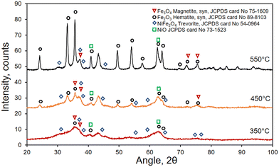
The catalysts prepared by a liquid-phase method via the oxalate route and calcined at different temperatures (350, 450, 550 °C) were physicochemically characterized by X-ray diffraction (XRD) to investigate their structure. The samples treated at 350 and 450 °C reveal diffraction patterns typical of amorphous or semi-crystalline phases, with broad peaks (Fig. 1). Nevertheless, especially at 450 °C, some sharper peaks appear, indicating the presence of a crystalline structure. These peaks can be assigned mainly to hematite, magnetite and trevorite, as reported in Fig. 1. Generally, an increased crystallinity is obtained by increasing temperature or calcination time. The sample treated at 550 °C shows the most defined peaks indicating higher crystallinity; most of these peaks are attributed to the presence of hematite (Fe2O3).The morphology of the samples was analyzed by transmission electron microscopy (TEM), as shown in Fig. 2. It reveals the presence of small spherical particles with a nanoporous structure. Increasing the calcination temperature, the particle size increases consequently, passing from 3–4 nm at 350 °C to 6 nm at 450 °C and 8–10 nm at 550 °C.
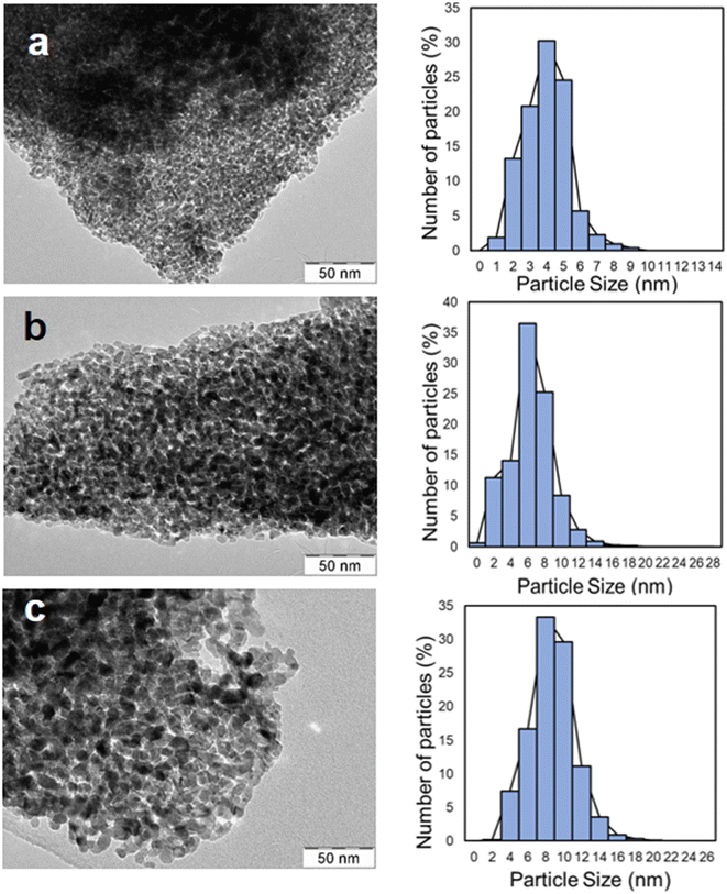 | ||
| Fig. 2 TEM micrographs and particle size distribution of the catalyst thermally treated at (a) 350 °C; (b) 450 °C; and (c) 550 °C. | ||
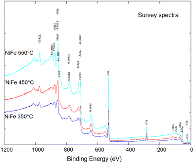
Fig. 3 shows the X-ray photoelectron spectroscopy (XPS) survey analysis of the three prepared samples treated at 350, 450, or 550 °C. The elements encountered in the XPS spectra are carbon of the sample holder, nickel, iron, and oxygen, revealing the synthesis procedure's effectiveness in obtaining pure compounds without undesired elements. The atomic surface percentages of each component, reported in Table 1, indicate a similar contribution of oxygen for all the compounds. In contrast, the iron/nickel ratio is about 1![[thin space (1/6-em)]](https://www.rsc.org/images/entities/char_2009.gif) :
:![[thin space (1/6-em)]](https://www.rsc.org/images/entities/char_2009.gif) 1 for NiFeOx treated at 350 °C or 450 °C, and about 2
1 for NiFeOx treated at 350 °C or 450 °C, and about 2![[thin space (1/6-em)]](https://www.rsc.org/images/entities/char_2009.gif) :
:![[thin space (1/6-em)]](https://www.rsc.org/images/entities/char_2009.gif) 1 for NiFeOx subjected to the highest thermal treatment (550 °C). As revealed by XRD results in Fig. 1, the larger content of iron in the NiFeOx 550 catalyst may be attributed to the formation of a well-defined hematite phase or a greater crystallinity for NiFe2O4 spinel structure.
1 for NiFeOx subjected to the highest thermal treatment (550 °C). As revealed by XRD results in Fig. 1, the larger content of iron in the NiFeOx 550 catalyst may be attributed to the formation of a well-defined hematite phase or a greater crystallinity for NiFe2O4 spinel structure.
| Iron Fe 2p3/2 (at%) | Nickel Ni 2p3/2 (at%) | Oxygen O 1s (at%) | Iron/nickel ratio | |
|---|---|---|---|---|
| NiFeOx 350 | 21.9 | 18.6 | 59.5 | 1.2 |
| NiFeOx 450 | 22.5 | 18.4 | 59.1 | 1.2 |
| NiFeOx 550 | 26.7 | 15.1 | 58.2 | 1.8 |
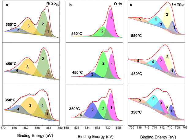
High-resolution spectra of NiFeOx compounds were deconvoluted and depicted in Fig. 4 for the interpretation of Ni 2p3/2 (Fig. 4a), O 1s (Fig. 4b), and Fe 2p3/2 (Fig. 4c) signals. According to several works in the literature,25–28 the interpretation of the Ni 2p spectrum of NiOx compounds is quite challenging due to many overlapping signals corresponding to Ni2+ from NiO or Ni(OH)2 and in this case even from NiFe2O4, and Ni3+ from NiOOH portions. Generally, the Ni2+ oxidation state is related to a binding energy of 854.0 ± 0.1 eV whereas Ni3+ is at 855.8 ± 0.1 eV. The other two peaks can be attributed to the shake-up lines of NiO. On the other hand, Biesinger et al.28 reported the binding energies values related to the Ni 2p of NiFe2O4 spinel structure corresponding to 4 peaks located at 854.5, 856.0, 861.4, and 864.7 eV. Herein, the Ni 2p3/2 deconvolution seems to have a predominant characteristic of NiFe2O4 for the sample treated at 350 °C, although the presence of NiO cannot be discarded.29 For Ni 2p spectra (Table 2) of NiFeOx 450 and NiFeOx 550 peak 1 at 854 ± 0.1 eV is ascribed to the Ni2+ component whereas peak 2 at 855.6 eV is characteristic of Ni3+ from NiOOH species. Peaks 3 and 4 are related to broad satellite peaks and shake-up lines of NiO, according to the literature.25–27 The area of peaks 1 and 2 is 7.13% and 44.6%, respectively, with a Ni3+/Ni2+ ratio of 6.25 for NiFeOx 450; for NiFeOx 550 this ratio thins out to 3.74, probably due to partial dehydration of NiOOH compound.
| Ni 2p3/2 | Peak 1 (eV) | Peak 2 (eV) | Peak 3 (eV) | Peak 4 (eV) |
|---|---|---|---|---|
| NiFeOx 350 | 854.2 | 855.9 | 860.0 | 864.2 |
| NiFeOx 450 | 853.9 | 855.6 | 861.0 | 864.4 |
| NiFeOx 550 | 854.1 | 855.6 | 860.9 | 864.5 |
Three peaks represent high-resolution O 1s spectra at 529.3 (peak 1), 530.9 (peak 2), and 532.9 eV (peak 3) corresponding to lattice oxide such as the oxygen bonded to the metals, hydroxide, or defective oxide-like Ni(OH)2 or NiOOH and adsorbed water, respectively (Table 3). For NiFeOx 350 the attribution of the fourth peak, at around 534.9 eV, is not straightforward. In Fig. 4b, peak 2 increases from 350 °C to 450 °C showing the maximum contribution of O bonded in hydroxide form, and again decreases at 550 °C, in agreement with the interpretation reported for Fig. 4a. O from adsorbed water (peak 3) decreases in the higher thermal treatment and disappears for NiFeOx 550 °C.
| O 1s | Peak 1 (eV) | Peak 2 (eV) | Peak 3 (eV) | Peak 4 (eV) |
|---|---|---|---|---|
| NiFeOx 350 | 529.4 | 530.9 | 532.9 | 534.9 |
| NiFeOx 450 | 529.2 | 530.8 | 532.9 | 534.9 |
| NiFeOx 550 | 529.4 | 530.9 | 532.9 | 534.9 |
For Fe 2p3/2 deconvolution (Fig. 4c and Table 4), in all samples, the contribution of metallic Fe and Fe2+ can be discarded for the binding energies of the peaks shifted toward higher values.28 Peaks 1 and 2 could be correlated to the overlapping between Fe3+ from Fe2O3 and the weakest bond of Fe3+ in NiFe2O4 spinel structure, whereas peaks 3 and 4 are attributed to FeOOH and the strongest bond of Fe3+ in the spinel. Peak 5, at higher binding energies, is a shake upline.28
| Fe 2p3/2 | Peak 1 (eV) | Peak 2 (eV) | Peak 3 (eV) | Peak 4 (eV) | Peak 5 (eV) |
|---|---|---|---|---|---|
| NiFeOx 350 | 709.6 | 710.8 | 712.2 | 713.9 | 717.1 |
| NiFeOx 450 | 709.3 | 710.6 | 712.2 | 714.0 | 717.5 |
| NiFeOx 550 | 709.3 | 710.6 | 712.2 | 713.3 | 717.5 |
2.2 Electrochemical characterization
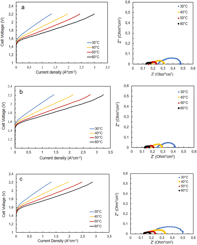
To understand the influence of temperature on cell performance, polarization curves have been recorded in a temperature range between 30–60 °C. Fig. 5 shows, for all three samples, an improvement in performance as the temperature increases. The best result is obtained with the catalyst calcined at 450 °C, which reaches 3.25 A cm−2 at 2.2 V. At the same cell voltage, the sample treated at 350 °C shows a value of 3 A cm−2 while the one calcined at 550 °C reaches 2.87 A cm−2. This behavior can be explained through the electrochemical impedance spectroscopy (EIS) results reported in Fig. 5 for the different cells based on the catalysts diversely treated. The cell based on NiFe-oxide 450 shows a lower charge transfer resistance (Rct) and thus polarization resistance (Rp) since the series resistance (Rs) is the same for all cells. The Rs is mainly due to the ohmic resistance of the membrane, which is the same in all experiments (Fumasep® FAA3-50). Ni–FeOx 550 shows the largest Rct, probably due to the formation of the hematite phase at higher temperatures, as reported in XRD and XPS measurements, which reduces the conductivity of the catalyst. Whereas, NiFeOx 350 and 450 catalysts exhibit a lower Rct associated with the larger presence of transition metal oxyhydroxides (NiOOH, FeOOH, etc.), which are the active species toward OER reaction in AEMWE.19,29 They form when the anode gets in contact with the KOH aqueous solution. Thus, most likely, catalysts treated at 350 and 450 °C are quite similar in terms of structural characteristics, but they slightly differ in the surface composition and surface area (considering the different particle sizes). De facto, the differences in performance, as observed in Fig. 6a, are not significant, being the behavior up to 1.9 V (2 A cm−2) almost identical for the cells based on 350 and 450 °C-treated catalysts, and only slightly lower for the cell based on the sample calcined at 550 °C. From the literature, it is known that the incorporation of iron into the nickel lattice can substantially enhance the OER activity.30 Fe atoms easily replace Ni atoms in the oxide/(oxy)hydroxide lattice. Iron appears to play a key role in facilitating the formation of high-surface-area structures, increasing in this way the catalytic activity. Even Fe impurities present in the KOH electrolytes can decrease the Tafel slope and increase the OER activity of the Ni catalysts.31,32 In the present case, a compromise between the amount of Fe and the surface area (correlated to the particle size) makes the sample treated at 450 °C the most performing material among the synthesized ones. It appears also more active than benchmark IrO2 and NiO commercial catalysts, as reported in Fig. 6b. By keeping the same experimental conditions (cell parameters, catalyst loading, etc.), the performance of NiFeOx 450 was 1.5 times higher than that achieved using IrO2 and double compared with NiO-based cells. This can be attributed to a higher presence of active sites, suitable surface properties, and a charge transfer facilitated by the presence of iron. | ||
| Fig. 6 Comparison of I–V curves at 60 °C (a) among the differently treated NiFeOx-based cells and (b) among the cells equipped with NiFe-oxide 450, IrO2, and NiO at the anode. | ||
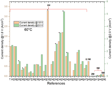
Analysing the results achieved in the literature, Fig. 7 summarises the current density values obtained in anion exchange membrane electrolysers (AEMEs) at 1.8 V and 2.0 V, and 60 °C. The best current density (3.3 A cm−2 at 1.8 V) was obtained by Kaczur et al.,33 employing an IrO2/Sustainion/Pt MEA and 1 M KOH solution. At 2.0 V, the best performance was reached by Chen et al.34 using IrO2/PFTP-13/Pt MEA. Remarkably, considering the non-PGM catalysts, the current densities at 1.8 and 2.0 V (1.5 and 2.7 A cm−2, respectively), obtained in this work (T.W.) with the NiFeOx treated at 450 °C, are the highest reported in the literature.20,21,29,33–47
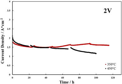
Fig. 8 shows the durability tests, carried out at 2 V, for the samples that showed the best cell performances. Although better current density values were observed from the polarization tests in the sample treated at 450 °C (Fig. 6a), a progressive loss in performance was noted in the durability test. Whereas, the sample calcined at 350 °C showed better results in terms of current density and stability at 2 V. For this sample, after the 40 hours of testing, a slight increase in the current density was observed, probably correlated to phenomena of surface modifications affecting the catalyst during operation.
3 Conclusions
The synthesis procedure via oxalate is a versatile route to obtain small particles if a proper calcination temperature is applied. In this work, it appears that relatively low-temperature treatments (350 and 450 °C) allow obtaining high catalytic activities for the oxygen evolution reaction in AEMWEs likely due to a smaller particle size of the obtained material. An outstanding performance of 3.25 A cm−2 at 2.2 V has been reached with the NiFe-oxide calcined at 450 °C, using a Fumasep® FAA3-50 membrane, whereas a more stable behaviour has been recorded with the sample treated at 350 °C. Further work will address the optimization of the Ni/Fe ratio and the analysis of the surface characteristics of the catalysts after long-term stability tests.4 Experimental section
4.1 Synthesis of electrocatalysts
Nickel nitrate hexahydrate (Ni(NO3)2·6H2O; purity ≥99.9%), iron nitrate (Fe(NO3)2·9H2O; ≥99%), NaOH (≥98%) and H2O2 35%, purchased by Sigma Aldrich, were used as starting materials. Ni/Fe oxide electrocatalysts were obtained by a liquid-phase method via oxalate.29 Nickel and iron nitrates in stoichiometric ratios 1![[thin space (1/6-em)]](https://www.rsc.org/images/entities/char_2009.gif) :
:![[thin space (1/6-em)]](https://www.rsc.org/images/entities/char_2009.gif) 2 were added in successive steps to the oxalic acid solution. Then, the chemical oxidation was performed by hydrogen peroxide at 35%. The precipitate obtained was first filtered under vacuum and then dried for 12 h at 80 °C. Calcination was carried out, in a muffle in the presence of oxygen, at 350 °C, 450 °C and 550 °C for 2 h to support the formation of nanocrystalline oxide structures.
2 were added in successive steps to the oxalic acid solution. Then, the chemical oxidation was performed by hydrogen peroxide at 35%. The precipitate obtained was first filtered under vacuum and then dried for 12 h at 80 °C. Calcination was carried out, in a muffle in the presence of oxygen, at 350 °C, 450 °C and 550 °C for 2 h to support the formation of nanocrystalline oxide structures.
4.2 Physicochemical characterization
The structure, morphology and surface properties of all the catalysts were investigated using XRD, TEM and XPS. XRD analysis was performed employing a Philips X'PERT XRD analyser. The X-ray diffraction pattern was measured with 2θ = 5–100° and a scanning rate of 0.01° s−1. The experimental tests were carried out through a Bruker D8 Advance diffractometer (Bruker, Billerica, MA, USA), voltage: 40 kV, current: 40 mA, anode: Cu (Kalpha1: 1.54060 Å, Kalpha2: 1.54439 Å).The survey spectra of the NiFeOx treated at 350, 450, or 550 °C and the deconvolution of Ni 2p3/2, O 1s, and Fe2p3/2 species were acquired by an X-ray photoelectron spectroscopy (XPS), Physical Electronics (PHI) 5800-01 using a monochromatic AlKα X-ray source at a power of 350 W.29,48 XPS data were processed through a detailed study of the literature for such compounds.25–28,48,49
Morphological analysis on the samples, after ultrasonic dispersion of the catalyst in isopropyl alcohol, was carried out by TEM using a FEI CM12 instrument equipped with LaB6 filament and a high-resolution camera.
4.3 Electrodes preparation
Anodes were prepared by mixing the Ni/Fe oxide electrocatalysts with 20 wt% of FAA3 ionomer. The ink was then sprayed directly onto one side of the anionic Fumasep® membrane (FAA3-50 from Fumatech, Bietigheim-Bissingen, Germany) to obtain a catalyst-coated membrane (CCM). The catalyst content, on each membrane, was 3 mg cm−2. Furthermore, two CCMs were made as references, with the same technique, with commercial IrO2 (Umicore) or NiO (Aldrich) as anodes. Cathode electrodes were made with a Pt loading of 0.5 mg cm−2 (40 wt% platinum on carbon Alfa Aesar). A 20 wt% of FAA3 ionomer was used. The catalytic ink was then sprayed onto a Sigracet 25-BC (SGL group) gas diffusion layer (GDL) to obtain a catalyst-coated electrode (CCE).50 Before using them both the electrodes were exchanged in 1 M KOH aqueous solution for 1 h.35 On the anode side, the CCM has been coupled with a sheet of Ni-foam which acts as a current collector.Finally, the electrodes, with a useful total geometrical area of 5 cm2, were coupled to realize a membrane-electrode assembly (MEA) by a cold assembling procedure. The electrochemical characterizations were then realized in a single-cell setup in a temperature range between 30–60 °C at atmospheric pressure. A supporting electrolyte solution was supplied to the anode side (1 M KOH) with a flow rate of 5 ml min−1.
4.4 Electrochemical characterization
Electrochemical measurements, in the single cell, were carried out by using a potentiostat–galvanostat device PGSTAT302 N equipped with an FRA module (Autolab). I–V curves were performed at a scan rate of 5 mV s−1. Ac-impedance analysis was used to determine the cell resistance. The electrochemical impedance spectroscopy (EIS) measurements were performed under potentiostatic control (at a cell voltage of 1.8 V) in a frequency range between 10 kHz and 100 mHz by frequency sweeping in the single sine mode. The amplitude of the sinusoidal excitation signal was 0.01 V r.m.s. Series resistance (Rs) was measured from the high-frequency intercept on the real axis of the Nyquist plot.Author contributions
Conceptualization, V. B. and I. G.; methodology, A. C. and V. B.; investigation, A. C. and C. L. V.; data curation, V. B., A. C., C. L. V. and I. G.; writing—original draft preparation, A. C., V. B. and C. L. V.; writing—review and editing, A. C., V. B., I. G. and C. L. V.; visualization, A. C., I. G., C. L. V. and V. B.; supervision, V. B. All authors have read and agreed to the published version of the manuscript.Conflicts of interest
The authors declare no conflict of interest.Acknowledgements
The authors thank the Italian ministry MUR for funding through the FISR2019 project AMPERE (FISR2019_01294). The authors also thank the support of Mr. G. Monforte (CNR ITAE) for XPS measurements.References
- W. Zhang, Y. Hu, L. Ma, G. Zhu, Y. Wang, X. Xue, R. Chen, S. Yang and Z. Jin, Progress and Perspective of Electrocatalytic CO2 Reduction for Renewable Carbonaceous Fuels and Chemicals, Adv. Sci., 2017, 5, 1700275 CrossRef PubMed.
- P. Sadorsky, Wind energy for sustainable development: Driving factors and future outlook, J. Cleaner Prod., 2021, 289, 125779 CrossRef.
- J. D. Fonseca, M. Camargo, J.-M. Commenge, L. Falk and I. D. Gil, Trends in design of distributed energy systems using hydrogen as energy vector: A systematic literature review, Int. J. Hydrogen Energy, 2019, 44, 9486–9504 CrossRef CAS.
- J. Kim, C. Huh and Y. Seo, End-to-end value chain analysis of isolated renewable energy using hydrogen and ammonia energy carrier, Energy Convers. Manage., 2022, 254, 115247 CrossRef CAS.
- J. A. Okolie, B. R. Patra, A. Mukherjee, S. Nanda, A. K. Dalai and J. A. Kozinski, Futuristic applications of hydrogen in energy, biorefining, aerospace, pharmaceuticals and metallurgy, Int. J. Hydrogen Energy, 2021, 46, 8885–8905 CrossRef CAS.
- S. Atilhan, S. Park, M. M. El-Halwagi, M. Atilhan, M. Moore and R. B. Nielsen, Green hydrogen as an alternative fuel for the shipping industry, Curr. Opin. Chem. Eng., 2021, 31, 100668 CrossRef.
- I. Dincer, Green methods for hydrogen production, Int. J. Hydrogen Energy, 2012, 37, 1954–1971 CrossRef CAS.
- J. Brauns and T. Turek, Alkaline water electrolysis powered by renewable energy: A review, Processes, 2020, 8, 248 CrossRef CAS.
- K. Ayers, The potential of proton exchange membrane–based electrolysis technology, Curr. Opin. Electrochem., 2019, 18, 9–15 CrossRef CAS.
- M. Chatenet, B. G. Pollet, D. R. Dekel, F. Dionigi, J. Deseure, P. Millet, R. D. Braatz, M. Z. Bazant, M. Eikerling, I. Staffell, P. Balcombe, Y. Shao-Horn and H. Schäfer, Water electrolysis: From textbook knowledge to the latest scientific strategies and industrial developments, Chem. Soc. Rev., 2022, 51, 4583–4762 RSC.
- J. R. Varcoe, P. Atanassov, D. R. Dekel, A. M. Herring, M. A. Hickner, P. A. Kohl, A. R. Kucernak, W. E. Mustain, K. Nijmeijer, K. Scott, T. Xu and L. Zhuang, Anion-exchange membranes in electrochemical energy systems, Energy Environ. Sci., 2014, 7, 3135–3191 RSC.
- W. da Silva Freitas, A. D'Epifanio, C. Lo Vecchio, I. Gatto, V. Baglio, V. C. A. Ficca, E. Placidi and B. Mecheri, Tailoring MOF structure via iron decoration to enhance ORR in alkaline polymer electrolyte membrane fuel cells, Chem. Eng. J., 2023, 465, 142987 CrossRef CAS.
- C. Santoro, A. Lavacchi, P. Mustarelli, V. Di Noto, L. Elbaz, D. R. Dekel and F. Jaouen, What is next in anion-exchange membrane water electrolyzers? Bottlenecks, benefits, and future, ChemSusChem, 2022, 15, e202200027 CrossRef CAS PubMed.
- N. Ul Hassan, M. Mandal, G. Huang, H. A. Firouzjaie, P. A. Kohl and W. E. Mustain, Achieving high-performance and 2000 h stability in anion exchange membrane fuel cells by manipulating ionomer properties and electrode optimization, Adv. Energy Mater., 2020, 10, 2001986 CrossRef CAS.
- P. Fortin, T. Khoza, X. Cao, S. Y. Martinsen, A. Oyarce Barnett and S. Holdcroft, High-performance alkaline water electrolysis using Aemion™ anion exchange membranes, J. Power Sources, 2020, 451, 227814 CrossRef CAS.
- Z. Xu, G. Chen, F. Yang, J. Jang, G. Liu, F. Xiao, Y. Sun, X. Qiu, W. Chen, D. Su, M. Gu and M. Shao, Graphene-supported Fe/Ni single atoms and FeNi alloy nanoparticles as bifunctional oxygen electrocatalysts for rechargeable zinc-air batteries, Electrochim. Acta, 2023, 458, 142549 CrossRef CAS.
- C. L. Vecchio, X. Lyu, I. Gatto, B. Zulevi, A. Serov, V. Baglio, C. L. Vecchio, I. Gatto and V. Baglio, Performance investigation of alkaline direct methanol fuel cell with commercial PGM-free cathodic materials, J. Power Sources, 2023, 561, 232732 CrossRef CAS.
- D. Henkensmeier, M. Najibah, C. Harms, J. Žitka, J. Hnát and K. Bouzek, Overview: State-of-the art commercial membranes for anion exchange membrane water electrolysis, J. Electrochem. Energy Convers. Storage, 2021, 18, 024001 CrossRef CAS.
- N. Du, C. Roy, R. Peach, M. Turnbull, S. Thiele and C. Bock, Anion-exchange membrane water electrolyzers, Chem. Rev., 2022, 122, 11830–11895 CrossRef CAS PubMed.
- S. Campagna Zignani, M. L. Faro, A. Carbone, C. Italiano, S. Trocino, G. Monforte and A. S. Aricò, Performance and stability of a critical raw materials-free anion exchange membrane electrolysis cell, Electrochim. Acta, 2022, 413, 140078 CrossRef CAS.
- A. Martinez-Lazaro, A. Caprì, I. Gatto, J. Ledesma-García, N. Rey-Raap, A. Arenillas, F. I. Espinosa-Lagunes, V. Baglio and L. G. Arriaga, NiFe2O4 hierarchical nanoparticles as electrocatalyst for anion exchange membrane water electrolysis, J. Power Sources, 2023, 556, 232417 CrossRef CAS.
- M. Plevová, J. Hnát and K. Bouzek, Electrocatalysts for the oxygen evolution reaction in alkaline and neutral media. A comparative review, J. Power Sources, 2021, 507, 230072 CrossRef.
- A. Brouzgou, Oxygen evolution reaction, in Methods for electrocatalysis: Advanced materials and allied applications, Springer International Publishing, 2020, pp. 149–169 Search PubMed.
- H. A. Miller, K. Bouzek, J. Hnat, S. Loos, C. I. Bernäcker, T. Weißgärber, L. Röntzsch and J. Meier-Haack, Green hydrogen from anion exchange membrane water electrolysis: a review of recent developments in critical materials and operating conditions, Sustainable Energy Fuels, 2020, 4, 2114–2133 RSC.
- K. L. Nardi, N. Yang, C. F. Dickens, A. L. Strickler and S. F. Bent, Creating highly active atomic layer deposited nio electrocatalysts for the oxygen evolution reaction, Adv. Energy Mater., 2015, 5, 1500412 CrossRef.
- S. Seo, I. J. Park, M. Kim, S. Lee, C. Bae, H. S. Jung, N.-G. Park, J. Y. Kim and H. Shin, An ultra-thin, un-doped NiO hole transporting layer of highly efficient (16.4%) organic–Inorganic hybrid perovskite solar cells, Nanoscale, 2016, 8, 11403–11412 RSC.
- D. Koushik, M. Jošt, A. Dučinskas, C. Burgess, V. Zardetto, C. Weijtens, M. A. Verheijen, W. M. M. Kessels, S. Albrecht and M. Creatore, Plasma-assisted atomic layer deposition of nickel oxide as hole transport layer for hybrid perovskite solar cells, J. Mater. Chem. C, 2019, 7, 12532–12543 RSC.
- M. C. Biesinger, B. P. Payne, A. P. Grosvenor, L. W. M. Lau, A. R. Gerson and R. S. C. Smart, Resolving surface chemical states in XPS analysis of first row transition metals, oxides and hydroxides: Cr, Mn, Fe, Co and Ni, Appl. Surf. Sci., 2011, 257, 2717–2730 CrossRef CAS.
- A. Caprì, I. Gatto, C. Lo Vecchio, S. Trocino, A. Carbone and V. Baglio, Anion exchange membrane water electrolysis based on nickel ferrite catalysts, ChemElectroChem, 2023, 10, e202201056 CrossRef.
- L. Trotochaud, S. L. Young, J. K. Ranney and S. W. Boettcher, Nickel–iron oxyhydroxide oxygen-evolution electrocatalysts: The role of intentional and incidental iron incorporation, J. Am. Chem. Soc., 2014, 136, 6744–6753 CrossRef CAS PubMed.
- R. Farhat, J. Dhainy and L. I. Halaoui, OER catalysis at activated and codeposited NiFe-Oxo/Hydroxide thin films is due to postdeposition surface-Fe and Is not sustainable without Fe in solution, ACS Catal., 2020, 10, 20–35 CrossRef CAS.
- D. A. Corrigan, The catalysis of the oxygen evolution reaction by iron impurities in thin film nickel oxide electrodes, J. Electrochem. Soc., 1987, 134, 377 CrossRef CAS.
- J. J. Kaczur, H. Yang, Z. Liu, S. D. Sajjad and R. I. Masel, Carbon dioxide and water electrolysis using new alkaline stable anion membranes, Front. Chem., 2018, 6, 263 CrossRef PubMed.
- N. Chen, S. Y. Paek, J. Y. Lee, J. H. Park, S. Y. Lee and Y. M. Lee, High-performance anion exchange membrane water electrolyzers with a current density of 7.68 A cm−2 and a durability of 1000 hours, Energy Environ. Sci., 2021, 14, 6338–6348 RSC.
- I. Gatto, A. Caprì, C. Lo Vecchio, S. Zignani, A. Patti and V. Baglio, Optimal operating conditions evaluation of an anion-exchange-membrane electrolyzer based on FUMASEP® FAA3-50 membrane, Int. J. Hydrogen Energy, 2023, 48, 11914–11921 CrossRef CAS.
- J. E. Park, M.-J. Kim, M. S. Lim, S. Y. Kang, J. K. Kim, S.-H. Oh, M. Her, Y.-H. Cho and Y.-E. Sung, Graphitic carbon nitride-carbon nanofiber as oxygen catalyst in anion-exchange membrane water electrolyzer and rechargeable metal–air cells, Appl. Catal., B, 2018, 237, 140–148 CrossRef CAS.
- A. Carbone, S. C. Zignani, I. Gatto, S. Trocino and A. S. Aricò, Assessment of the FAA3-50 polymer electrolyte in combination with a NiMn2O4 anode catalyst for anion exchange membrane water electrolysis, Int. J. Hydrogen Energy, 2020, 45, 9285–9292 CrossRef CAS.
- C. Busacca, S. C. Zignani, A. Di Blasi, O. Di Blasi, M. Lo Faro, V. Antonucci and A. S. Aricò, Electrospun NiMn2O4 and NiCo2O4 spinel oxides supported on carbon nanofibers as electrocatalysts for the oxygen evolution reaction in an anion exchange membrane-based electrolysis cell, Int. J. Hydrogen Energy, 2019, 44, 20987–20996 CrossRef CAS.
- I. V. Pushkareva, A. S. Pushkarev, S. A. Grigoriev, P. Modisha and D. G. Bessarabov, Comparative study of anion exchange membranes for low-cost water electrolysis, Int. J. Hydrogen Energy, 2020, 45, 26070–26079 CrossRef CAS.
- Z. Liu, S. D. Sajjad, Y. Gao, H. Yang, J. J. Kaczur and R. I. Masel, The effect of membrane on an alkaline water electrolyzer, Int. J. Hydrogen Energy, 2017, 42, 29661–29665 CrossRef CAS.
- A. Konovalova, H. Kim, S. Kim, A. Lim, H. S. Park, M. R. Kraglund, D. Aili, J. H. Jang, H.-J. Kim and D. Henkensmeier, Blend membranes of polybenzimidazole and an anion exchange ionomer (FAA3) for alkaline water electrolysis: Improved alkaline stability and conductivity, J. Membr. Sci., 2018, 564, 653–662 CrossRef CAS.
- N. Lee, D. T. Duong and D. Kim, Cyclic ammonium grafted poly (arylene ether ketone) hydroxide ion exchange membranes for alkaline water electrolysis with high chemical stability and cell efficiency, Electrochim. Acta, 2018, 271, 150–157 CrossRef CAS.
- B. Motealleh, Z. Liu, R. I. Masel, J. P. Sculley, Z. Richard Ni and L. Meroueh, Next-generation anion exchange membrane water electrolyzers operating for commercially relevant lifetimes, Int. J. Hydrogen Energy, 2021, 46, 3379–3386 CrossRef CAS.
- P. Stilli, S. Bonizzoni, F. Lohmann-Richters, L. Beverina, A. Papagni and P. Mustarelli, Aquivion®-based anionic membranes for water electrolysis, Electrochim. Acta, 2022, 405, 139834 CrossRef CAS.
- M. Chen, M. Mandal, K. Groenhout, G. McCool, H. M. Tee, B. Zulevi and P. A. Kohl, Self-adhesive ionomers for durable low-temperature anion exchange membrane electrolysis, J. Power Sources, 2022, 536, 231495 CrossRef CAS.
- T. Caielli, A. R. Ferrari, S. Bonizzoni, E. Sediva, A. Caprì, M. Santoro, I. Gatto, V. Baglio and P. Mustarelli, Synthesis, characterization and water electrolyzer cell tests of poly(biphenyl piperidinium) Anion exchange membranes, J. Power Sources, 2023, 557, 232532 CrossRef CAS.
- C. Simari, M. H. Ur Rehman, A. Caprì, I. Gatto, V. Baglio and I. Nicotera, High-performance anion exchange membrane water electrolysis by polysulfone grafted with tetramethyl ammonium functionalities, Mater. Today Sustain., 2023, 21, 100297 CrossRef.
- C. Lo Vecchio, A. S. Aricò and V. Baglio, Application of low-cost Me-N-C (Me = Fe or Co) electrocatalysts derived from EDTA in direct methanol fuel cells (DMFCs), Materials, 2018, 11, 1193 CrossRef PubMed.
- A. P. Grosvenor, B. A. Kobe, M. C. Biesinger and N. S. McIntyre, Investigation of multiplet splitting of Fe 2p XPS spectra and bonding in iron compounds, Surf. Interface Anal., 2004, 36, 1564–1574 CrossRef CAS.
- A. Carbone, R. Pedicini, I. Gatto, A. Saccà, A. Patti, G. Bella and M. Cordaro, Development of polymeric membranes based on quaternized polysulfones for AMFC applications, Polymers, 2020, 12, 283 CrossRef CAS PubMed.
| This journal is © Institute of Process Engineering of CAS 2023 |

