
 Open Access Article
 This Open Access Article is licensed under a Creative Commons Attribution-Non Commercial 3.0 Unported Licence
Polyaniline-derived carbon nanofibers with a high graphitization degree loading ordered PtNi intermetallic nanoparticles for oxygen reduction reaction†
Yujuan
Zhuang
ab,
Jiao
Yang
b,
Lingwei
Meng
ab,
Chuanming
Ma
b,
Lishan
Peng
 *ab,
De
Chen
*c and
Qingjun
Chen
*ab
*ab,
De
Chen
*c and
Qingjun
Chen
*ab
aSchool of Rare Earth, University of Science and Technology of China, Hefei, China
bKey Laboratory of Rare Earths, Ganjiang Innovation Academy, Chinese Academy of Sciences, Ganzhou, China. E-mail: lspeng@gia.cas.cn; qjchen@gia.cas.cn
cNorwegian University of Science and Technology, Trondheim, Norway. E-mail: de.chen@ntnu.no
First published on 17th July 2023
Abstract
At present, the catalysts commercially used for the oxygen reduction reaction of the cathode of proton exchange membrane fuel cells (PEMFCs) are carbon-supported platinum-based catalysts. However, the carbon supports are susceptible to corrosion under harsh working conditions, which greatly shortens the life of the catalysts. Highly stable carbon supports are urgently required for high-performance PEMFCs. In this work, we developed structure-stable and highly graphitized three-dimensional network carbon nanofibers (CNF) derived from polyaniline by heat treatment at 1200 °C. The CNF-1200-based catalyst (PtNi/CNF-1200) loaded with PtNi nanoparticles showed excellent stability. After 5000 cycles from 1.0 to 1.5 V in oxygen saturated 0.1 M HClO4 electrolyte, the losses in the half-wave potential and mass activity were only 5 mV and 15%, respectively, far lower than those of commercial Pt/C. The high graphitization degree of CNF-1200 promotes the corrosion resistance of the catalyst. In addition, nitrogen doping effectively facilitates the catalyst–support interaction, stabilizes the highly dispersed PtNi nanoparticles, and improves the stability and activity of PtNi/CNF-1200.
Keywords: Support stability; Graphitization degree; Nitrogen doping; Oxygen reduction reaction.
1 Introduction
Proton exchange membrane fuel cells (PEMFCs) are favoured for the commercialization of fuel cell vehicles owing to their fast start-up speed, low operating temperature, and high energy conversion efficiency. Moreover, the clean feedstocks and products associated with PEMFCs play a pivotal role in achieving carbon peak and neutrality targets.1,2 However, the sluggish kinetics of oxygen reduction reaction (ORR) occurring at the cathode is a critical factor hampering the commercial deployment of PEMFCs.3–6 Presently, commercial oxygen reduction catalysts for PEMFCs are mainly carbon-supported platinum-based catalysts, which are composed of Pt or Pt alloy nanoparticles dispersed on carbon materials.7 Unfortunately, in addition to the high price of platinum, carbon-supported platinum-based catalysts have the disadvantages of low activity and poor stability.8–10 Especially in terms of stability, current commercial platinum–carbon catalysts is difficult to meet the DOE target for support stability with respect to the loss of mass activity (MA) <40% after 5000 cycles at the potential range of 1.0–1.5 V.11–13 Therefore, improving the stability of platinum–carbon catalysts is of great significance for its large-scale application.The decline in the activity of platinum–carbon catalysts during ORR can be attributed to the dissolution and agglomeration of Pt nanoparticles, as well as the corrosion of carbon supports, both of which decrease the number of active sites, thereby reducing the catalyst activity.14–19 The corrosion of carbon support also hinders the transmission of proton, electron, and gas, resulting in irreversible performance loss.20 In order to improve the activity and durability of Pt-based catalysts, a variety of approaches have been explored, including constructing core–shell structures, and alloying Pt with transition metals (M), especially the intermetallic PtM nanoparticles.21–24 However, the issue of carbon support corrosion has usually been ignored. Black Pearls 2000 and KetjenBlack EC-600-JD are presently-used commercial carbon supports, but they both possess amorphous carbon structure with a low degree of graphitization, resulting in the susceptibility to oxidation and corrosion under harsh operating conditions, ultimately leading to poor catalyst performance in fuel cells.25 Graphene is a promising carbon support due to its high conductivity and specific surface area. However, it is prone to agglomeration and poor dispersion.26,27 Carbon nanotubes, on the other hand, have excellent electrical conductivity and corrosion resistance, but they are difficult to anchor catalysts due to their chemical inertness.28,29 Therefore, there is an urgent need to develop corrosion-resistant carbon supports for stabilizing Pt-based nanoparticle, which would facilitate the creation of high-performance Pt-based catalysts.
Herein, we reported a three-dimensional network carbon nanofibers (CNF) with a high degree of graphitization as a robust carbon support for platinum–carbon catalysts. The CNF network was fabricated via high temperature treatment of three-dimensional network polyaniline (PANI) nanofibers synthesized by the one-step hydrothermal method. After loading PtNi nanoparticles, the PtNi/CNF-1200 catalyst exhibited a high catalytic activity with a half-wave potential (E1/2) of 0.919 V and mass activity (MS) of 0.52 A mgPt−1. Furthermore, the PtNi/CNF-1200 catalyst demonstrated impressive stability, with only a 2.9 mV and 38% decrease in E1/2 and MS, respectively, after 30![[thin space (1/6-em)]](https://www.rsc.org/images/entities/char_2009.gif) 000 cycles of low potential (0.6–1.0 V). These properties far exceeded those of commercial Pt/C. More importantly, only 5 mV and 15% were observed in E1/2 and MS of PtNi/CNF-1200 after 5000 cycles of high potential (1.0–1.5 V). The excellent stability of the CNF-1200 was attributed to the high degree of graphitization, which enhanced the corrosion-resistant ability at high oxidation potentials. The three-dimensional network structure of CNF together with its abundant N dopant facilitated the uniform dispersion of nanoparticles and enhanced the anchoring effect between the support and the nanoparticles.
000 cycles of low potential (0.6–1.0 V). These properties far exceeded those of commercial Pt/C. More importantly, only 5 mV and 15% were observed in E1/2 and MS of PtNi/CNF-1200 after 5000 cycles of high potential (1.0–1.5 V). The excellent stability of the CNF-1200 was attributed to the high degree of graphitization, which enhanced the corrosion-resistant ability at high oxidation potentials. The three-dimensional network structure of CNF together with its abundant N dopant facilitated the uniform dispersion of nanoparticles and enhanced the anchoring effect between the support and the nanoparticles.
2 Results and discussion
Fig. 1 illustrates the preparation process of the PtNi/CNF-1200 catalyst introduced in this study. First, we synthesized polyaniline (PANI) precursors by using ammonium persulfate as an initiator along with aniline as the monomer. The PANI fiber was further stabilized by the hydrothermal method. The results of Fourier transform infrared (FTIR) spectroscopy spectrum (Fig. S1a†) and X-ray diffraction (XRD) pattern (Fig. S1b†) confirmed the successful synthesis of PANI with a uniform distribution and an average diameter of 30 nm (Fig. S1c†). Next, the PANI precursors were heat-treated under argon flow at 1200 °C for 1 hour, resulting in the transformation of the PANI precursors into carbon nanofibers. The carbon nanofibers were later pickled with 0.5 M H2SO4 to remove any impurities and heat-treated at 600 °C for 2 hours to enhance the stabilization of the carbon structure. The final product was labelled as CNF-1200 which exhibited a three-dimensional network structure with an average diameter of 29 nm (Fig. S1d†). The XRD pattern (Fig. S1b†) for CNF-1200 indicated the presence of two broad diffraction peaks at ∼25° and ∼43°, corresponding to the (002) and (100) faces of graphitic carbon (PDF#41-1487), respectively, suggesting that the CNF-1200 exhibited certain graphitization characteristics. Finally, PtNi/CNF-1200 was synthesized by loading PtNi nanoparticles onto the CNF-1200 support. | ||
| Fig. 1 Schematic illustration of the fabrication of PtNi/CNF-1200. | ||
To study the graphitization degree of the prepared carbon samples, the Raman spectrum was conducted and the results were compared in Fig. S2.† All these samples possessed characteristic D and G bands at 1334 cm−1 and 1580 cm−1, respectively, which correspond to the disordered and defective carbon atoms (D-band) and sp2 hybridized graphitic carbon atoms (G-band).30–32 The intensity ratio of ID/IG for CNF-1200 (ID/IG = 0.92) was lower than the CNF-800 (ID/IG = 0.94), indicating a higher degree of graphitization. This result revealed a higher heat treatment temperature can obtain a higher degree of graphitization for the CNF. Commercial Ketjenblack support ECP-600JD (KBC-600) (ID/IG = 1.14) had a poor degree of graphitization with more disordered and defective carbon. Furthermore, when these carbon materials were loaded with PtNi nanoparticles, the graphitization degree of PtNi/CNF-1200 (ID/IG = 0.94) was also better than that of commercial 20% Pt/C (ID/IG = 0.96) and far better than that of PtNi/KBC-600 (ID/IG = 1.12) (Fig. 2h). The high degree of graphitization can enhance the corrosion resistance of carbon supports, even under harsh working conditions.
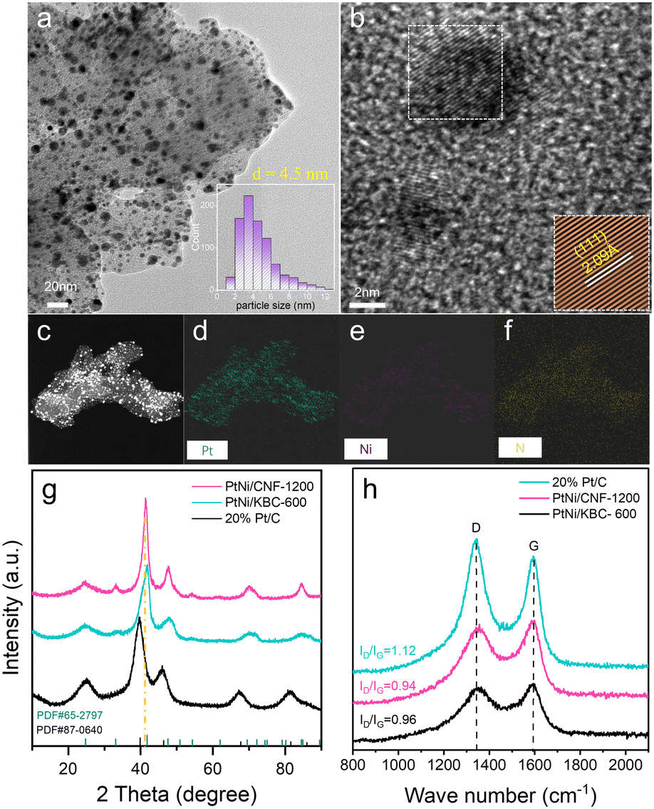 | ||
| Fig. 2 (a) HRTEM image and particle size distribution (inset) for PtNi/CNF-1200; (b) HRTEM image for PtNi/CNF-1200, the inset shows the corresponding information about lattice fringes; (c) HRTEM image and (d–f) energy-dispersive X-ray spectroscopy (EDS) mapping for PtNi/CNF-1200; (g) XRD patterns and (h) Raman spectra for PtNi/CNF-1200, PtNi/KBC-600, and 20% Pt/C. | ||
Surface area and pore size distribution for CNF-1200 and other reference samples were measured by nitrogen adsorption and desorption isotherms (Fig. S3†). The surface area of CNF-1200 was much smaller than that of KBC-600. After these carbon samples were loaded with PtNi nanoparticles by one-step heat treatment with ammonia. The surface area of PtNi/KBC-600 (765 m2 g−1) decreased sharply compared to KBC-600 (964 m2 g−1). However, the surface area of PtNi/CNF-1200 (96 m2 g−1) only decreased by 30 m2 g−1 compared to CNF-1200 (126 m2 g−1), indicating that the nanoparticles were mainly attached to the outer surface of carbon nanofibers. The catalyst on the outer surface was conducive to the exposure of the catalytic active site, which was further confirmed by the relatively large electrochemically active surface area (ECSA) of Pt (73 m2 g−1) for PtNi/CNF-1200 (Fig. 4a).
High-resolution transmission electron microscopy (HRTEM) image (Fig. 2a) showed PtNi nanoparticles uniformly dispersed on CNF-1200 with an average size of 4.5 nm. The average size of PtNi nanoparticles loaded onto KBC-600 was only 3.5 nm. however, some of the particles have agglomerated, resulting in unusually large sizes (Fig. S4a†). The energy-dispersive X-ray spectroscopy (EDS) mapping of PtNi/CNF-1200 (Fig. 2c–f) showed that the elements Pt, Ni and N were evenly distributed on CNF-1200, and the PtNi/KBC-600 had the same properties (Fig. S4c–f†). It can be seen from Fig. S4f and 2f and Table S3† that the content of the N element in PtNi/KBC-600 was significantly lower than that in PtNi/CNF-1200. The N element in PtNi/KBC-600 was mainly derived from the ammonia treatment process, while a large part of the N element in PtNi/CNF-1200 came from the raw aniline precursor. The nitrogen contents for PtNi/CNF-1200 and PtNi/KBC-600 detected by X-ray photoelectron spectroscopy (XPS) measurement also demonstrated that the former had a higher N content (Table S1†).
The XRD patterns (Fig. 2g) confirmed the successful synthesis of intermetallic structures of PtNi (PDF# 65-2797) on CNF-1200 and KBC-600. The peaks at ∼24.6° and ∼33.1° for PtNi/CNF-1200 and PtNi/KBC-600 were attributed to the (001) and (110) reflections of ordered structure. Compared to the commercial Pt/C, the peak positions of PtNi/CNF-1200 and PtNi/KBC-600 shifted towards higher angles, which could be attributed to Pt lattice contraction resulting from Pt–Ni alloying since Ni has a smaller atomic radius than Pt. Furthermore, it was found that the angle shift of PtNi/CNF-1200 was slightly smaller than that of PtNi/KBC-600. Additionally, for the (111) crystal plane, PtNi/CNF-1200 (Fig. 2b, d = 2.09 Å) had a larger lattice constant than PtNi/KBC-600 (Fig. S4b,†d = 2.06 Å). This difference might result from the high nitrogen content in PtNi/CNF-1200 that facilitates charge transfer between N and PtNi, consequently enhancing the interaction between the support and PtNi.23,33,34
The XPS fine spectra of N 1s and Pt 4f for these catalysts directly reflected the charge transfer between N and Pt. The high-resolution Pt 4f spectra (Fig. 3a) showed that PtNi/CNF-1200 shifted to higher binding energy compared to PtNi/KBC-600. Moreover, it can be seen from the N 1s spectra (Fig. 3b) that the binding energy of N of PtNi/CNF-1200 was lower than that of PtNi/KBC-600. This result suggested that PtNi/CNF-1200 had more electron transfer from Pt to N relative to PtNi/KBC-600. This is mainly due to the more N content in PtNi/CNF-1200 than PtNi/KBC-600, and the N element has relatively stronger electronegativity.
 | ||
| Fig. 3 (a) High-resolution Pt 4f XPS spectra for PtNi/CNF-1200, PtNi/KBC-600, and 20% Pt/C; (b) high-resolution N 1s XPS spectra for PtNi/CNF-1200 and PtNi/KBC-600. | ||
Ring disk electrode (RDE) tests were performed using a typical three-electrode system in 0.1 M HClO4 electrolyte to evaluate the catalytic performance of all catalysts, and all potentials obtained from the RDE tests were calibrated relative to RHE without iR compensation. Cyclic voltammograms (CVs) were tested in an Ar-saturated solution at 50 mV s−1 to calculate the ECSAs of different catalysts by using the hydrogen under potential adsorption/desorption charges. It can be seen from Fig. 4a that PtNi/CNF-1200 had a high ECSA (73 m2 g−1), indicating a high utilization rate of Pt on CNF-1200. The polarization curves were acquired by conducting measurements at a scanning speed of 5 mV s−1 and a rotational speed of 1600 rpm for rotating disk electrodes in an O2-saturated solution. The half-wave potential of PtNi/CNF-1200 reached 0.919 V, which was slightly higher than that of PtNi/KBC-600 (0.910 V) and much higher than that of Pt/C (0.867 V). It indicated that PtNi/CNF-1200 had higher kinetic activity (Fig. 4b). In addition, the mass activity of PtNi/CNF-1200 is optimal (0.52 A mgPt−1). The specific activity of PtNi/CNF-1200 was lower than that of PtNi/KBC-600, mainly because of its larger ECSA (Fig. 4c).
 | ||
| Fig. 4 (a) Cyclic voltammograms; (b) polarization curves and (c) mass activity (MA) and specific activity (SA) for PtNi/CNF-1200, PtNi/KBC-600 and 20% Pt/C; polarization curves for (d) PtNi/CNF-1200; (e) PtNi/KBC-600 and (f) 20% Pt/C before and after 5000 cycles in a high potential range of 1.0–1.5 V; (g) MA comparison of PtNi/CNF-1200, PtNi/KBC-600, and 20% Pt/C before and after 5000 potential cycles; (h) H2O2 yield and electron transfer number. | ||
Accelerated durability tests (ADTs) were conducted in a high potential range from 1.0 to 1.5 V to evaluate the degradation of the carbon supports in the O2-saturated 0.1 M HClO4 electrolyte. A low potential range (0.6–1.0 V) of ADTs was conducted to evaluate the degradation of the PtNi and Pt nanoparticles on different supports. After 5000 cycles (1.0–1.5 V), the E1/2 of PtNi/CNF-1200 only decreased by 5 mV, while that of PtNi/KBC-600 and Pt/C decreased by 13 mV and 41 mV, respectively (Fig. 4d–f). In terms of mass activity change (Fig. 4g), PtNi/CNF-1200 exhibited a decline of 15%, far lower than PtNi/KBC-600 (36%) and Pt/C (70%). Based on the above analysis, it is evident that the carbon support of Pt/C experienced the most severe corrosion. This was further confirmed by observing the Raman spectra, which showed an obvious increase in the ID/IG value of Pt/C from 0.96 (Fig. 2h) to 0.99 (Fig. S14†) after the ADTs. The ECSA of Pt/C (Fig. S7d†) decreased significantly after 5000 cycles, while PtNi/CNF-1200 (Fig. S5d†) and PtNi/KBC-600 (Fig. S6d†) increased. This may be due to negligible corrosion of PtNi/CNF-1200 and PtNi/KBC-600 under high potential cycles. Meanwhile, trace amounts of Ni dissolved from PtNi during ADTs benefited to exposing more Pt sites. The high potential cycle test of PtNi/CNF-800 was also carried out (Fig. S8†). The E1/2 of PtNi/CNF-800 decreased by 10 mV, and the MA decreased by 23.2%, indicating that CNF-1200 with a high graphitization degree had better stability and corrosion resistance. It can be seen from the results of the low potential cycle test (Fig. S5–S7†) that PtNi/CNF-1200 had almost no loss of ECSA after 30000 cycles, and the E1/2 only decreased by 2.9 mV, which was much lower than the attenuation of PtNi/KBC-600 (22.9 mV) and Pt/C (38 mV). At the same time, we noted that the mass activity of PtNi/CNF-1200 exhibited the least decline (38%). These findings suggest that CNF-1200 is more effective in enhancing the corrosion resistance of Pt-based catalysts.
To further examine the ORR reaction pathway and selectivity of each catalyst, we conducted rotating ring disk electrode (RRDE) testing to analyze the hydrogen peroxide (H2O2) yield during ORR. Our results revealed that PtNi/CNF-1200 exhibited the lowest H2O2 yield (below 0.9%) over a wide potential range. We also calculated the average number of electron transfers at PtNi/CNF-1200 as approximately 3.98 in the potential range of 0.2 to 0.8 V, indicating that oxygen was involved in the reaction through the 4 e− transfer pathway (as shown in Fig. 4h).
Fig. 5a and b display the morphology of PtNi/CNF-1200 and PtNi/KBC-600 following the high-potential cycles, respectively. Meanwhile, Fig. S9–S12† provide an improved depiction of lattice spacing and particle cell distribution. Among the three catalysts, the morphological changes were most pronounced in PtNi/KBC-600, where an average particle size increase of 0.6 nm following the high-potential cycles was documented. Additionally, a substantial aggregation of nanoparticles was detected, with the size of larger particles being close to 20 nm (as shown in Fig. 5b). The morphological changes in Pt/C were secondary, with a particle size increase from 3.0 nm to 3.3 nm after the high-potential cycles (Fig. S11–S12†). The average size of PtNi particles in PtNi/CNF-1200 changed little (Fig. 5a).
 | ||
| Fig. 5 HRTEM image and particle size distribution (inset) for (a) PtNi/CNF-1200 and (b) PtNi/KBC-600 after 5000 cycles in a high potential range (1.0–1.5 V); high-resolution C 1s XPS spectra for PtNi/CNF-1200, PtNi/KBC-600, and 20% Pt/C before (c) and after (d) 5000 cycles in a high potential range (1.0–1.5 V). | ||
The XRD patterns of these samples before and after the ADTs show that the crystal structure of these samples did not change (Fig. S13†). Nevertheless, it can be seen from the FTIR spectra that the peak around 1200 cm−1 (C–O stretching vibration peak) of the sample after ATDs was more prominent, especially for PtNi/KBC-600, indicating that the carbon support was oxidized at a high potential (Fig. S15†). Additionally, by comparing the high-resolution C 1s XPS spectra before (Fig. 5c) and after (Fig. 5d) the high-potential ADTs, it is obvious that the areas of C–O and C![[double bond, length as m-dash]](https://www.rsc.org/images/entities/char_e001.gif) O for PtNi/KBC-600 significantly increased compared with that of PtNi/CNF-1200, indicating that PtNi/KBC-600 was seriously corroded. Table S2† displays the atomic content of different types of C before and after the ADTs for PtNi/CNF-1200, PtNi/KBC-600 and Pt/C according to XPS data. The atomic fraction of C–C for PtNi/CNF-1200, PtNi/KBC-600 and 20% Pt/C all decreased after ATDs, with PtNi/CNF-1200 decreasing the least (4.1 at%).
O for PtNi/KBC-600 significantly increased compared with that of PtNi/CNF-1200, indicating that PtNi/KBC-600 was seriously corroded. Table S2† displays the atomic content of different types of C before and after the ADTs for PtNi/CNF-1200, PtNi/KBC-600 and Pt/C according to XPS data. The atomic fraction of C–C for PtNi/CNF-1200, PtNi/KBC-600 and 20% Pt/C all decreased after ATDs, with PtNi/CNF-1200 decreasing the least (4.1 at%).
3 Conclusions
In summary, the catalyst composed of PtNi nanoparticles loading on CNF-1200 exhibited excellent activity and stability of oxygen reduction. After 5000 cycles in the high potential interval of 1.0–1.5 V in the 0.1 M HClO4 electrolyte, the E1/2 of PtNi/CNF-1200 only decreased by 5 mV, which was lower than that of PtNi/KBC-600 (13 mV) and commercial Pt/C (41 mV). The mass activity retention rate of PtNi/CNF-1200 is 85%, which was much better than PtNi/KBC-600 and commercial Pt/C with 64% and 30% preservation, respectively. Through a comparative analysis of microscopic morphology and elemental composition before and after ADTs, it can be deduced that PtNi/CNF-1200 exhibited superior resistance to corrosion. This can be attributed to the three-dimensional network structure of the polyaniline-derived support, which had a high degree of graphitization and structural stability. In addition, the N-doping further enhanced the anchoring effect between the support and PtNi nanoparticles, which further promoted the stability of the catalyst. These results illustrate the importance of support selection in improving the durability of Pt-based electrocatalysts.4 Experimental sections
4.1 Materials
Aniline (C6H7N, ≥99.5%), p-phenylenediamine (C6H8N2, AR, 97%), ammonium persulfate ((NH4)2S2O8, AR, 98.5%), phytic acid solution (C6H18O24P6, 50% solution), ethanol (C2H6O, 99.7%), all purchased from Shanghai McLean Biochemical Technology Co., Ltd. Platinum(II) acetylacetonate (C10H14O4Pt, Pt(acac)2, 97%) and nickel(II) acetylacetonate (NiC10H14O4, Ni(acac)2, 98%) purchased from Shanghai Titan Technology Co., Ltd. KetjenBlack EC-600-JD purchased from Hefei Kejing Materials Technology Co., Ltd. 20% Pt/C purchased from Sigma Aldrich (Shanghai) Trading Co., Ltd. The water (18 MΩ cm) used in all experiments was purified through a Millipore system.4.2 Synthesis of polyaniline nanofibers
Weigh 22 mg of p-phenylenediamine and 1.14 g of ammonium persulfate and dissolve them in 5 ml and 10 ml of water solution for use, then take 0.44 ml of aniline and 0.92 ml of phytic acid into 25 ml of polytetrafluoron lining, then put the p-phenylenediamine solution into the lining and stir evenly, and then pour the ammonium persulfate solution into the lining quickly and stir continuously. The temperature of this process was controlled at 0–15 °C. After the reaction lasted for 30 min, the lining was put into the reaction kettle for hydrothermal reaction at 180 °C for 3 hours in the blast drying oven. This step is to further fix the morphology of polyaniline nanofibers. Finally, the product was cleaned with water and ethanol, and freeze-dried in the freeze-dryer.4.3 Synthesis of CNF-1200 and CNF-800
The polyaniline nanofibers prepared above were ground into powder and calcined twice in a tubular furnace. The first calcination temperature was 1200 °C for 1 hour in flowing argon gas with a heating rate of 5 °C min−1. Then acid-washed with 0.5 M dilute sulfuric acid solution at 80 °C for 10 h under magnetic stirring, and then washed with water and dried. The second calcination temperature was 600 °C for 2 h in flowing argon gas with a heating rate of 5 °C min−1. The product treated in this process was named CNF-1200. When the first calcination temperature was set at 800 °C and other conditions remained unchanged, the product obtained was named CNF-800.4.4 Synthesis of PtNi/CNF-1200, PtNi/CNF-800 and PtNi/KBC-600
Weigh 100 mg of the above prepared CNF-1200 in 15 ml ethanol, then add 65 mg Pt(acac)2 and 40 mg Ni(acac)2, sonicate for 15 min, and stir for 2 hours. Then dry in a 60 °C drying oven for 12 h. The sample was then placed in a tubular furnace and treated with ammonia at 570 °C for 9 h, with a heating rate of 5 °C min−1. The heat-treated samples were pickled with 0.5 M dilute sulfuric acid solution for 5 h at 80 °C under magnetic stirring. Finally, the samples were dried in a vacuum drying oven at 60 °C for 12 h. Final Pt and Ni loadings were 18% and 2.7%, respectively, measured by ICP-OES. The product was designated as PtNi/CNF-1200. For comparison, PtNi nanoparticles deposited on KetjenBlack (denoted as PtNi/KBC-600) and CNF-800 (denoted as PtNi/CNF-800) were also synthesized following the same procedure.Conflicts of interest
The authors declare no conflict of interest.Acknowledgements
The work was supported by the National Natural Science Foundation of China (No. 92061125, 22209186), Beijing Natural Science Foundation (No. Z200012), Jiangxi Natural Science Foundation (No. 20212ACB213009, 20223BBG74004), and Youth Innovation Promotion Association, CAS (No. 2023343).Notes and references
- V. Yarlagadda, M. K. Carpenter, T. E. Moylan, R. S. Kukreja, R. Koestner, W. Gu, L. Thompson and A. Kongkanand, Boosting fuel cell performance with accessible carbon mesopores, ACS Energy Lett., 2018, 3, 618–621 CrossRef CAS.
- H. A. Gasteiger and N. M. Markovic, Just a dream-or future reality?, Science, 2009, 324, 48–49 CrossRef CAS PubMed.
- L. Peng, J. Yang, Y. Yang, F. Qian, Q. Wang, D. Sun-Waterhouse, L. Shang, T. Zhang and G. I. N. Waterhouse, Mesopore-rich Fe–N–C catalyst with FeN4–O–NC single-atom sites delivers remarkable oxygen reduction reaction performance in alkaline media, Adv. Mater., 2022, 34, 2202544 CrossRef CAS PubMed.
- M. Wang, L. Wang, Q. Li, D. Wang, L. Yang, Y. Han, Y. Ren, G. Tian, X. Zheng, M. Ji, C. Zhu, L. Peng and G. I. N. Waterhouse, Regulating the coordination geometry and oxidation state of single-atom Fe sites for enhanced oxygen reduction electrocatalysis, Small, 2023, 19, 2300373 CrossRef CAS PubMed.
- Y. Hu, M. Zhu, X. Luo, G. Wu, T. Chao, Y. Qu, F. Zhou, R. Sun, X. Han, H. Li, B. Jiang, Y. Wu and X. Hong, Coplanar Pt/C nanomeshes with ultrastable oxygen reduction performance in fuel cells, Angew. Chem., Int. Ed., 2021, 60, 6533–6538 CrossRef CAS PubMed.
- J. Wang, C.-X. Zhao, J.-N. Liu, D. Ren, B.-Q. Li, J.-Q. Huang and Q. Zhang, Quantitative kinetic analysis on oxygen reduction reaction: A perspective, Nano Mater. Sci., 2021, 3, 313–318 CrossRef CAS.
- H. Cruz-Martínez, H. Rojas-Chávez, P. Matadamas-Ortiz, J. Ortiz-Herrera, E. López-Chávez, O. Solorza-Feria and D. Medina, Current progress of Pt-based ORR electrocatalysts for PEMFCs: An integrated view combining theory and experiment, Mater. Today Phys., 2021, 19, 100406 CrossRef.
- Y.-J. Wang, W. Long, L. Wang, R. Yuan, A. Ignaszak, B. Fang and D. P. Wilkinson, Unlocking the door to highly active ORR catalysts for PEMFC applications: Polyhedron-engineered Pt-based nanocrystals, Energy Environ. Sci., 2018, 11, 258–275 RSC.
- M. Liu, Z. Zhao, X. Duan and Y. Huang, Nanoscale structure design for high-performance Pt-based ORR catalysts, Adv. Mater., 2019, 31, 1802234 CrossRef PubMed.
- S. G. Ji, H. C. Kwon, T.-H. Kim, U. Sim and C. H. Choi, Does the encapsulation strategy of Pt nanoparticles with carbon layers really ensure both highly active and durable electrocatalysis in fuel cells?, ACS Catal., 2022, 12, 7317–7325 CrossRef CAS.
- H.-Y. Lee, H. Y. Ted, C.-H. Shin, A. Fortunelli, S. G. Ji, Y. Kim, T.-H. Kang, B.-J. Lee, B. V. Merinov and W. A. Goddard III, Low temperature synthesis of new highly graphitized N-doped carbon for Pt fuel cell supports, satisfying DOE 2025 durability standards for both catalyst and support, Appl. Catal., B, 2023, 323, 122179 CrossRef CAS.
- Y. Kim, H. E. Bae, D. Lee, J. Kim, E. Lee, S. Oh, J.-H. Jang, Y.-H. Cho, M. Karuppannan and Y.-E. Sung, High-performance long-term driving proton exchange membrane fuel cell implemented with chemically ordered Pt-based alloy catalyst at ultra-low Pt loading, J. Power Sources, 2022, 533, 231378 CrossRef CAS.
- Z. Qiao, S. Hwang, X. Li, C. Wang, W. Samarakoon, S. Karakalos, D. Li, M. Chen, Y. He, M. Wang, Z. Liu, G. Wang, H. Zhou, Z. Feng, D. Su, J. S. Spendelow and G. Wu, 3D porous graphitic nanocarbon for enhancing the performance and durability of Pt catalysts: A balance between graphitization and hierarchical porosity, Energy Environ. Sci., 2019, 12, 2830–2841 RSC.
- Z. Qiao, C. Wang, Y. Zeng, J. S. Spendelow and G. Wu, Advanced nanocarbons for enhanced performance and durability of platinum catalysts in proton exchange membrane fuel cells, Small, 2021, 17, 2006805 CrossRef CAS PubMed.
- M. Tarasevich, V. Bogdanovskaya, E. Loubnin and L. Reznikova, Comparative study of the corrosion behavior of platinum-based nanosized cathodic catalysts for fuel cells, Prot. Met., 2007, 43, 689–693 CrossRef CAS.
- A. Kostuch, I. A. Rutkowska, B. Dembinska, A. Wadas, E. Negro, K. Vezzù, V. Di Noto and P. J. Kulesza, Enhancement of activity and development of low Pt content electrocatalysts for oxygen reduction reaction in acid media, Molecules, 2021, 26, 5147 CrossRef CAS PubMed.
- J. C. Meier, C. Galeano, I. Katsounaros, A. A. Topalov, A. Kostka, F. Schüth and K. J. Mayrhofer, Degradation mechanisms of Pt/C fuel cell catalysts under simulated start–stop conditions, ACS Catal., 2012, 2, 832–843 CrossRef CAS.
- T. Zhang, P. Wang, H. Chen and P. Pei, A review of automotive proton exchange membrane fuel cell degradation under start-stop operating condition, Appl. Energy, 2018, 223, 249–262 CrossRef.
- L. Huang, S. Zaman, X. Tian, Z. Wang, W. Fang and B. Y. Xia, Advanced platinum-based oxygen reduction electrocatalysts for fuel cells, Acc. Chem. Res., 2021, 54, 311–322 CrossRef CAS PubMed.
- J. Hou, M. Yang, C. Ke, G. Wei and J. Zhang, Optimizing the structural design of a nanocomposite catalyst layer for PEM fuel cells for improving mass-specific power density, Nanoscale, 2020, 12, 13858–13878 RSC.
- X. Zhao and K. Sasaki, Advanced Pt-based core–shell electrocatalysts for fuel cell cathodes, Acc. Chem. Res., 2022, 55, 1226–1236 CrossRef CAS PubMed.
- Y. Xiong, L. Xiao, Y. Yang, F. J. DiSalvo and H. D. Abruña, High-loading intermetallic Pt3Co/C core–shell nanoparticles as enhanced activity electrocatalysts toward the oxygen reduction reaction (ORR), Chem. Mater., 2018, 30, 1532–1539 CrossRef CAS.
- X. Zhao, C. Xi, R. Zhang, L. Song, C. Wang, J. S. Spendelow, A. I. Frenkel, J. Yang, H. L. Xin and K. Sasaki, High-performance nitrogen-doped intermetallic PtNi catalyst for the oxygen reduction reaction, ACS Catal., 2020, 10, 10637–10645 CrossRef CAS.
- Z. Yu, C. Liu, J. Chen, Z. Yuan, Y. Chen and L. Wei, High-performance Fe–N–C electrocatalysts with a “chain mail” protective shield, Nano Mater. Sci., 2021, 3, 420–428 CrossRef CAS.
- M. S. Garapati and R. Sundara, Highly efficient and ORR active platinum-scandium alloy-partially exfoliated carbon nanotubes electrocatalyst for Proton Exchange Membrane Fuel Cell, Int. J. Hydrogen Energy, 2019, 44, 10951–10963 CrossRef CAS.
- Y. Li, Y. Li, E. Zhu, T. McLouth, C.-Y. Chiu, X. Huang and Y. Huang, Stabilization of high-performance oxygen reduction reaction Pt electrocatalyst supported on reduced graphene oxide/carbon black composite, J. Am. Chem. Soc., 2012, 134, 12326–12329 CrossRef CAS PubMed.
- Z. Ji, M. Perez-Page, J. Chen, R. G. Rodriguez, R. Cai, S. J. Haigh and S. M. Holmes, A structured catalyst support combining electrochemically exfoliated graphene oxide and carbon black for enhanced performance and durability in low-temperature hydrogen fuel cells, Energy, 2021, 226, 120318 CrossRef CAS.
- M. N. Roudbari, R. Ojani and J. B. Raoof, Nitrogen functionalized carbon nanotubes as a support of platinum electrocatalysts for performance improvement of ORR using fuel cell cathodic half-cell, Renewable Energy, 2020, 159, 1015–1028 CrossRef CAS.
- X. Wu, R. Liu, J. Zhao and Z. Fan, Advanced carbon materials with different spatial dimensions for supercapacitors, Nano Mater. Sci., 2021, 3, 241–267 CrossRef CAS.
- S. Yuan, L.-L. Cui, Z. Dou, X. Ge, X. He, W. Zhang and T. Asefa, Nonprecious bimetallic sites coordinated on N-doped carbons with efficient and durable catalytic activity for oxygen reduction, Small, 2020, 16, 2000742 CrossRef CAS PubMed.
- A. C. Ferrari and D. M. Basko, Raman spectroscopy as a versatile tool for studying the properties of graphene, Nat. Nanotechnol., 2013, 8, 235–246 CrossRef CAS PubMed.
- X. Xie, L. Peng, H. Yang, G. I. N. Waterhouse, L. Shang and T. Zhang, MIL-101-derived mesoporous carbon supporting highly exposed Fe single-atom sites as efficient oxygen reduction reaction catalysts, Adv. Mater., 2021, 33, 2101038 CrossRef CAS PubMed.
- M. Escudero-Escribano, P. Malacrida, M. H. Hansen, U. G. Vej-Hansen, A. Velázquez-Palenzuela, V. Tripkovic, J. Schiøtz, J. Rossmeisl, I. E. L. Stephens and I. Chorkendorff, Tuning the activity of Pt alloy electrocatalysts by means of the lanthanide contraction, Science, 2016, 352, 73–76 CrossRef CAS PubMed.
- L. A. Kibler, A. M. El-Aziz, R. Hoyer and D. M. Kolb, Tuning reaction rates by lateral strain in a palladium monolayer, Angew. Chem., Int. Ed., 2005, 44, 2080–2084 CrossRef CAS PubMed.
Footnote |
| † Electronic supplementary information (ESI) available. See DOI: https://doi.org/10.1039/d3im00056g |
| This journal is © Institute of Process Engineering of CAS 2023 |