
 Open Access Article
 This Open Access Article is licensed under a Creative Commons Attribution-Non Commercial 3.0 Unported Licence
Microkinetic studies for mechanism interpretation in electrocatalytic CO and CO2 reduction: current and perspective
Xiaofei
Lu
 ,
Keisuke
Obata
and
Kazuhiro
Takanabe
*
,
Keisuke
Obata
and
Kazuhiro
Takanabe
*
Department of Chemical System Engineering, School of Engineering, The University of Tokyo, 7-3-1 Hongo, Bunkyo-ku, Tokyo 113-8656, Japan. E-mail: takanabe@chemsys.t.u-tokyo.ac.jp
First published on 26th May 2023
Abstract
Microkinetic analysis can establish the relationship between the atomic-level reaction mechanism and macroscopic observables, such as reaction rates, product selectivity, Tafel slope, reaction order, isotopic effect, and apparent activation energy, at given operating conditions. This relationship is essential in the rational design of electrocatalysts and reactor configurations. In recent years, microkinetic analysis, particularly Tafel and reaction order analysis, has seen significant advancements in its application for interpreting reaction mechanisms in electrocatalytic CO and CO2 reduction. This review summarizes the progress in understanding the complex kinetic processes through theoretical microkinetic simulation modeling and experimental measurements. However, the reaction mechanisms derived from microkinetic analysis are disputed, complicating efforts to design electrocatalysts. This review analyzes the discrepancies in the literature and elucidates deeper insights into experimental discrepancies. The importance of local reaction environments in the intrinsic kinetic behavior of electrocatalysts is highlighted. The report also discusses the challenges and limitations of microkinetic analysis. Finally, the review suggests some perspectives on future investigations. Overall, this review is expected to provide new insights, critical interpretation, and guidance for the future development of microkinetic measurements and analysis.
Broader contextElectrochemical CO2 reduction powered by renewable energy offers a sustainable and cost-effective approach to convert harmful CO2 emissions into valuable chemicals and fuels, reducing the dependency on fossil fuels and contributing to the development of a circular carbon economy. Microkinetic analysis plays a crucial role in the design and optimization of catalytic systems, which allows for the determination of the reaction pathways and the identification of the rate-determining step involved in CO2 electroreduction. Nevertheless, the reaction mechanisms derived from microkinetic analysis remain debatable, impeding the establishment of design guidelines for effective catalysts and the optimization of reaction conditions. This review attempts to summarize the recent advancements in the understanding of complex kinetic processes through theoretical microkinetic simulation modeling and experimental measurements. The discrepancies in the literature are analyzed, highlighting the significance of local reaction environments in the intrinsic kinetic behavior of electrocatalysts. Furthermore, it discusses the challenges and limitations of microkinetic analysis in electrochemical CO2 reduction. Finally, operando spectroscopies as complementary tools are proposed, and strengthening the connection between experiments and computation is emphasized to increase its accuracy and reliability in reaction mechanism interpretation. |
1. Introduction
The electrocatalytic reduction of CO and CO2 (CO(2)) may offer an alternative route to produce carbonaceous fuels and chemicals in decarbonized societies, especially with the decrease in renewable electricity prices.1–3 Therefore, huge research efforts have been dedicated to this direction in the last few decades, demonstrating the potential of producing CO, formate, or hydrocarbons via electrocatalytic CO(2) reduction.4–7 However, despite the added motivation of the gas-diffusion electrode (GDE), these processes still suffer from low efficiency and require the development of active and selective electrocatalysts for any large-scale implementation.8–11 Unfortunately, interpreting the atomic-level reaction mechanisms remains controversial due to the involvement of multiple electron and proton transfers, hampering the establishment of robust design principles for electrocatalysts.Microkinetic modeling is a powerful tool for addressing rate-determining steps (RDS) and detailed reaction pathways, both of which are explanatory and predictive in rational catalyst design.12–18 For example, microkinetic analysis using density functional theory (DFT) calculations provides a deeper understanding of why Au and Ag are at the top of the experimentally obtained volcano trend for CO evolution during electrocatalytic CO2 reduction, revealing the moderate binding affinity of the adsorbed carboxylate (*COOH) on Au and Ag.19–22 Additionally, it distinguishes Cu from other elements as the only metal to go beyond C1 products efficiently in electrocatalytic CO2 reduction.4,23 Furthermore, Sargent and his colleagues developed a machine-learning-accelerated, high-throughput DFT framework to identify Cu–Al alloys as promising electrocatalysts for C2H4 production.24 Despite the wide application of DFT-based microkinetic modeling, using it as a quantitative predictive tool is challenging.25 Therefore, enhancing the connections between computation and experimental observables is essential to increase the effectiveness of microkinetic modeling.
Microkinetic analysis from experiments is essential for creating precise DFT-based microkinetic models for the active site and its environment. Tafel analysis is one of the most common experimental techniques used to understand the RDS in electrocatalytic CO2 reduction.26,27 In the classical analysis, the experimentally observed Tafel slope is compared with the theoretically derived slope to identify the corresponding RDS. However, this method has several assumptions, including steady-state reactions and no mass transportation limitations under reaction conditions, the constant assumptions (0 or 1) of intermediate surface coverage, and an electron transfer coefficient of 0.5.28–31 To point out the RDS, additional methods are necessary, as different proposed RDS can yield the same identified Tafel slope.26,27,29 For instance, one electron transfer and proton-coupled electron transfer (PCET) over Ag and Au both yield a Tafel slope of approximately 120 mV dec−1.26,31,32 Thus, the isotopic effect (hydrogen/deuterium) or operando spectroscopies are necessary to provide deeper insights into the RDS. Moreover, the type of proton donor and CO2 source must be identified since protons can come from various sources including H2O, free proton (H+), and H-containing species (e.g., HCO3−); CO2 can be supplied by gas-phase CO2 or bicarbonate.20,31,33 The apparent reaction orders with respect to pH and reactants (e.g., partial pressure of CO(2) (PCO(2)) and bicarbonate concentration (cHCO3−)) can distinguish between them.34 Temperature dependence can also provide a fingerprint of the reaction pathways. Overall, rigorous microkinetic analysis using Tafel slopes, kinetic isotope effects (KIE), apparent reaction orders, and temperature sensitivity can deconvolve the complexity of interface reactions occurring on the electrode and elucidate the reaction mechanisms, which are highly desired in rational catalyst design.
Up to this point, several issues have arisen in interpreting experimental kinetic data, related to measuring the intrinsic kinetic behavior of catalysts.26,33,35,36 For example, local environments and experimental designs can significantly affect the experimental results, which can, in turn, mislead the mechanistic elucidation.37–42 Moreover, some assumptions have limitations. The theoretically derived slopes, for instance, generally assume an extreme coverage of the adsorbed species (θ = 0 or 1).43,44 However, several studies have claimed to observe some key intermediates via joint spectroscopic/DFT techniques,45–47 including the negatively charged CO dimer on Cu during CO reduction,48 adsorbed CO and CHx on Cu-based catalysts,49–51 and proposed COOH intermediate over polycrystalline Ag (pc-Ag)52 during CO2 reduction. Additionally, the charge transfer coefficient is always assumed to be 0 or 0.5 for elementary steps, although, in practice, it is a function of both overpotentials and reorganization energy.29,30 Therefore, revisiting microkinetic analysis and understanding its limitations during CO(2) reduction are of crucial in elucidating atomic-level reaction mechanisms.
This review mainly focuses on the development, challenges, and limitations of microkinetic analysis during electrocatalytic CO(2) reduction. Firstly, it reviews the DFT-based microkinetic modeling of various products, such as CO, formic acid, CH4, and C2+. It addresses the theoretically derived Tafel slopes and reaction orders under the assumption of different RDSs. Secondly, it summarizes and discusses the experimentally observed parameters (e.g., Tafel slopes, reaction orders, and kinetic isotopic effects) and corresponding reaction mechanisms over various electrocatalysts in electrocatalytic CO(2) reduction. Special attention is given to the discussions of the reported discrepancies in the literature. Moreover, the existing challenges and limitations in the microkinetic analysis are interpreted from different aspects, such as intrinsic kinetic measurements, dynamically restructured catalyst, the complexity of electrolyte effects, intermediate surface coverage assumption, and electron transfer coefficient. Finally, this review provides an outlook on the future development of kinetic analysis in rational catalyst design. It implies the importance of operando spectroscopies and computational methods as complementary tools in microkinetic modeling. This review provides deeper insights into microkinetic analysis in electrocatalytic CO(2) reduction and emphasizes the importance of these complementary tools for future research.
2. DFT-based microkinetic simulation of electrocatalytic CO(2) reduction
The pioneering work by Hori et al. examined a variety of metal electrodes for the electrocatalytic CO2 reduction reaction, having stimulated the development of heterogeneous catalysts in this field.53–57 Among them, copper is a unique catalyst sitting at the top of the “volcano” plot for electrocatalytic CO2 reduction, in which both CO- and formate-paths prevail, yielding a variety of CO2-reduction products.4 In contrast, there have been several elements reported to achieve exclusive production of single products (e.g., CO, HCOOH). More specifically, p-block electrodes, such as indium or tin, selectively produce formate while keeping the concurrent hydrogen evolution reaction (HER) silent.58–62 In addition, although the metals in groups 8–10 of the periodic table favor the HER over the CO2 reduction routes, gold and silver metal electrocatalysts direct the reaction toward the CO route selectively, achieving a faradaic efficiency toward CO (FECO) greater than 90%.32,33,63,64 Interestingly, DFT calculations could interpret the activity-selectivity map by quantifying the free energies of reaction intermediates, e.g., *COOH, *CO, and *OCOH species, in agreement with the experimentally obtained results. These findings validate the reliability of DFT-based microkinetic modeling in electrocatalytic CO2 reduction, where the active site and its electrochemical environment have been taken into account due to advancements in the computation.37,65–72 The widespread success has made computational methods a routine practice as quantitative predictive tools.This section reviews the recent development of DFT-based microkinetic simulation of electrocatalytic CO(2) reduction, mainly focusing on key intermediates (descriptors) and proposed reaction pathways. Moreover, the theoretically calculated kinetic parameters (e.g., Tafel slope, reaction order, and KIE) are also summarized by assuming different RDSs in proposed reaction pathways during electrocatalytic CO(2) reduction.
2.1 Key intermediates (descriptors) and reaction pathways for C1 formation
Although the reaction pathways of CO and formic acid/formate formation (HCOOH/HCOO−) over different catalysts remains debated, the key intermediates (descriptors) have been well-defined by recent calculation studies. Chan and co-workers depicted a unified mechanistic picture of electrocatalytic CO2 reduction toward CO on transition metals (TMs), molecular complexes (e.g., phthalocyanine (Pc)), and metal–nitrogen-doped carbon catalysts (MNCs) by using the Newns–Andersen model, where the effects of the adsorbate–field interactions for all the intermediates were taken into account.73 The general kinetic activity of CO evolution was determined by two activity descriptors, namely the free energy of adsorption (ΔG) of CO2 and COOH, as shown in Fig. 1a and b. Fig. 1a exhibited the unified activity volcano for the CO evolution on both TM and MNC catalysts, and the maximum theoretical activity appeared when both ΔGCO2 and ΔGCOOH were close to 0 eV. Moreover, the RDS could be identified at any given potential using computed *CO2, *COOH, and *CO free energies. More specifically, CO2 adsorption was the RDS when the points appeared above the parity line (e.g., TM), while *COOH formation was the RDS if the points were below the line (e.g., NiNx and FeNx). They found that on MNCs, electron transfer to CO2 was facile. Moreover, *CO desorption could be the RDS with very negative adsorption energies (Fig. 1b), where the surface was poisoned by *CO (e.g., Pd and Pt). Feaster et al. used a DFT-based microkinetic model to describe the experimentally observed trend of formate production over TMs, showing why Sn was the best-known metal electrocatalyst (Fig. 1c). The *OCHO binding energy was singled out as the most important descriptor.74 The potential-dependent selective regions for formate, CO, and H2 were plotted by combining descriptor (ΔGCO, ΔGOH) maps, as shown in Fig. 1d. The dashed green line represented the thermodynamic boundary condition defined by ΔGCOOH = ΔGHCOO.75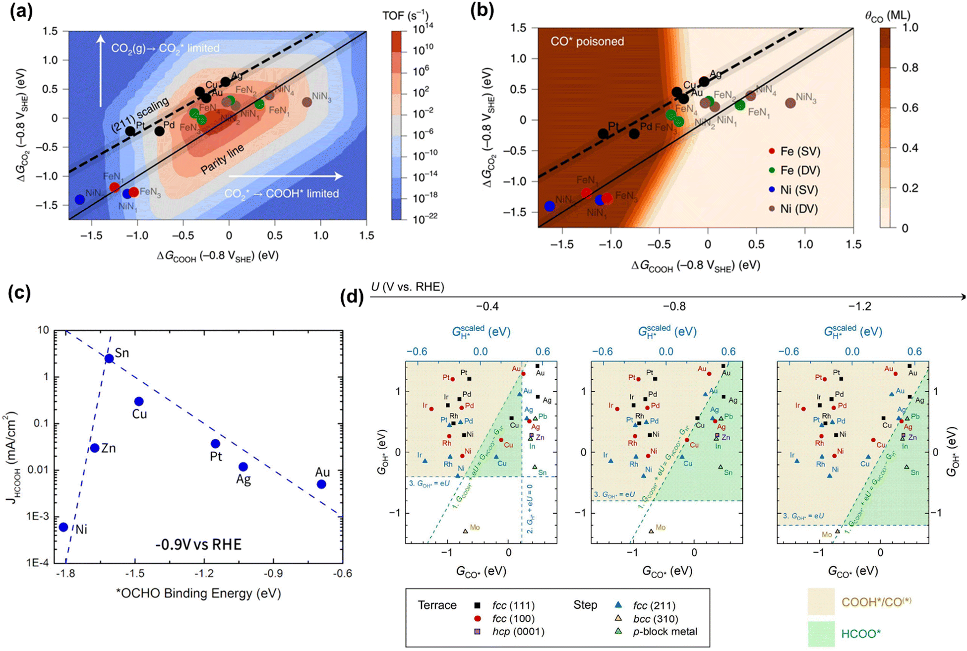 | ||
| Fig. 1 (a) The trends in the binding of key intermediates (ΔGCO2 and ΔGCOOH) and corresponding rate map at −0.8 V versus standard hydrogen electrode (SHE) and pH 2 for CO evolution over TMs and MNCs. (b) CO coverage map (θCO) in monolayers (ML) with the same points showing which surfaces are poisoned by CO. Reproduced with permission.73 Copyright 2021, nature publishing group. (c) The trends in binding *OCHO for formic acid production over TMs. Reproduced with permission.74 Copyright 2017. (d) The potential-dependent selective regions for formate, CO, and H2 were plotted by combining descriptor (ΔGCO, ΔGOH) maps. Reproduced with permission.75 Copyright 2020, from Elsevier. | ||
Additionally, the nature of the electrogenerated reactive nucleophilic species were also identified as important descriptor to determine the selectivity between CO and HCOOH/HCOO− during CO2 reduction.76–78 For metal tetraphenylporphyrin (MTPP),76 the electrogenerated metal-hydride or phlorin-hydride (M: In, Sn, Rh, Cd, Ga, and Pd) could attack the carbon of the CO2 to form C–H bond, which resulted in the formation of HCOOH/HCOO−.79 On the contrary, the reduced metal-centers (e.g., Fe, Co, Ni) triggered the formation of the metal–carbon bond with CO2, which then gave rise to the formation of CO.76 Similarly, it also has been reported that the thermodynamically generated surface adsorbed hydrogen on Pd could significantly decrease the overpotential of formate production in aqueous bicarbonate solutions.77 And the product distributions on PC–Cu and Au were shifted from CO to formate at low overpotentials after chemical modification with a poly(4-vinylpyridine) (P4VP) layer, which was suggested to promote a surface hydride mechanism for formate formation on both electrodes.80
2.2 Key intermediates (descriptors) during reaction pathways for CH4 and C2+ formation
CO is demonstrated as a key intermediate on the pathway to CH4 and C2+ compounds during electrocatalytic CO2 reduction.57,81 Only copper-based electrocatalysts have been reported to convert CO2 into CH4 or C2+ products at moderate rates under ambient pressure and temperature, which was rationalized that Cu-based electrodes possess the balanced chemisorption energy of CO and proton (Fig. 2a).4 Accordingly, this review only focuses on the microkinetic models for CO electroreduction towards CH4 and C2+ on Cu based electrodes.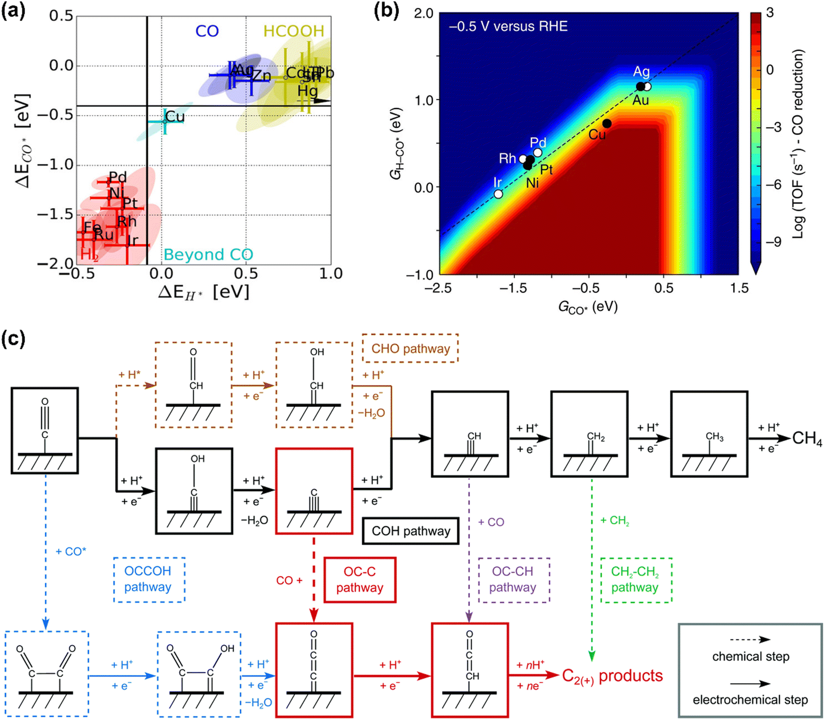 | ||
| Fig. 2 (a) Metal classification for CO2 electroreduction. Reproduced with permission.23 Copyright 2017, Wiley. (b) Rate map at −0.5 V versus reversible hydrogen electrode (RHE) for CH4 formation over Cu. Reproduced with permission.82 Copyright 2017, Nature. (c) Schematic diagram of reaction steps for C2+ over Cu. Reproduced with permission.84 Copyright 2021, from RSC Publishing. | ||
Nørskov and co-workers developed a first-order absorbate interaction model for CH4 formation (Fig. 2b), where the proton-electron transfer from *CO to *H-CO was considered as RDS for CH4 formation and the stepped facet was predicted to deliver significantly higher rates than flat facets due to the preferred *CO protonation on the stepped facet.82 Regarding C2+ products, the processes are very complex due to the involvement of multiple proton and electron transfers. Goodpaster et al. built microkinetic modeling on Cu(100) to predict ΔG of elementary steps for C2+ formation, where the electrochemical potential, solvent, and electrolyte were considered. This model revealed that C–C bond formation occurred via CO dimerization at low-applied potential, which shifted to the coupling between adsorbed CO and CHO at high overpotentials.83 Peng et al. also established microkinetic modeling to identify the key steps toward CH4 and C2+ products on Cu(100) (Fig. 2c), where two simple thermodynamic descriptors (ΔGC* and ΔGCO*) were proposed. The selectivity between C2+ and CH4 was determined through the energetic difference between barriers for *CCO and *CH formation.84
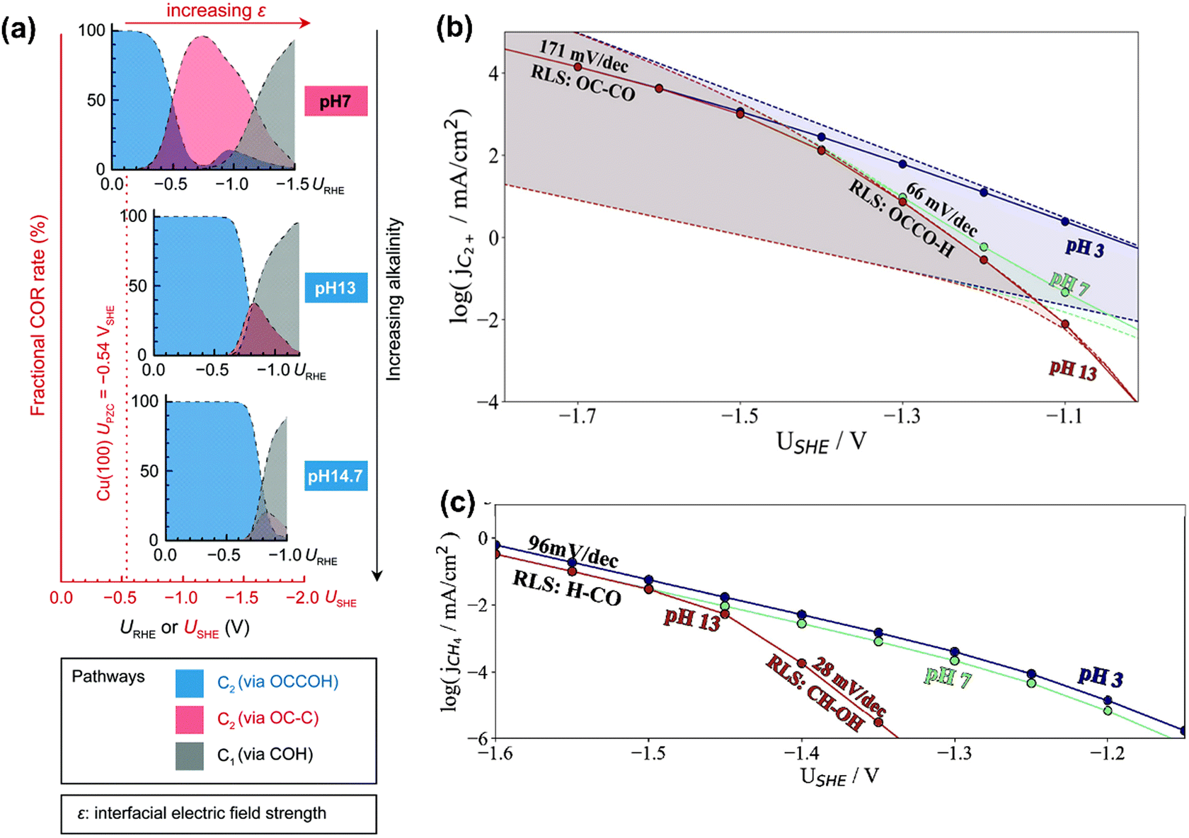
In terms of pH dependence on CH4 and C2+ formation, in Peng's model (Fig. 3a), the dominant pathway for C2+ formation was *CO and *C coupling at neutral pH and moderate potential windows (e.g., −0.4 V to −1 V vs. reversible hydrogen electrode (RHE)), which shifted to the coupling between *CO and *COH at high pH. For CH4 formation, it preferred the formation *COH first and then went through a *C intermediate under wider pH and potential windows. Moreover, some other pathways have been proposed for CH4 (e.g., *CHO pathways) and C2+ (e.g., *OC–CH pathway and *CH2CH2 pathway).84 Xiao et al. used an implicit solvation model on Cu(111) to interpret the reaction pathways and examine the pH effects, showing that higher pH favored C–C coupling through the dimerization of *CO and the common intermediate *COH was shared by CH4 and C2H4 at neutral pH.85 Hahn and co-workers also performed microkinetic analysis using a constant-potential model to understand the Tafel slopes and pH dependences on the formation of C2+ and CH4.86,87 They found that their different rate-limiting steps lead to distinctive potential dependent Tafel slope and pH effects on C2+ and CH4 formation, as shown in Fig. 3b and c, respectively. Clearly, C2+ formation at low overpotentials (>−1.4 V vs. standard hydrogen electrode (SHE)) was limited by the first proton–electron transfer to the *OCCO using H2O as proton source at pH = 7 and 13, while the corresponding RDS was shifted to CO dimerization at high overpotentials with increased Tafel slopes. In contrast, H3O+ was the predominant proton donor and CO–CO dimerization was the RDS throughout the considered potential range at pH = 3. For CH4 formation at pH = 13, the RDS shifted from the *CH–OH formation with a Tafel slope of 28 mV dec−1 at low overpotentials (>−1.45 V vs. SHE) to the *CO–H formation with a Tafel slope of 96 mV dec−1 at high overpotential. Reducing the electrolyte pH led to a change of RDS to the first protonation step using H3O+ as the proton donor through the investigated potential range.86 Given the challenge of large uncertainties in calculated rates, the theoretical models need to be verified by experimental results.
 | ||
| Fig. 3 (a) Product distributions of CO electroreduction on Cu(100) under different bulk pH conditions. Reproduced with permission.84 Copyright 2021, from RSC Publishing. (b) Simulated current densities using a microkinetic model based on the DFT-calculated energetics on Cu(100). (c) Simulated current densities using a microkinetic model based on the DFT-calculated reaction energetics on Cu(211). Reproduced with permission.86 Copyright 2022, American Chemical Society. | ||
2.3 Theoretically calculated kinetic parameters
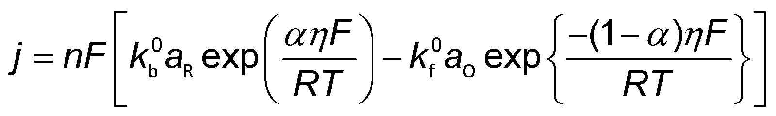
Conventionally, the microkinetic analysis helps to obtain three important physical parameters: the Tafel slope, reaction order, and KIE (hydrogen/deuterium). The Tafel slope (b) has been empirically defined in eqn (1):η = a + b![[thin space (1/6-em)]](https://www.rsc.org/images/entities/i_char_2009.gif) log(j) log(j) | (1) |
| O + ne− ↔ R | (2) |
 | (3) |
 | (4) |
 | (5) |
 | ||
| Fig. 4 The scheme of all possible reaction pathways for various products in electrocatalytic CO2 reduction. Formation of (a) CO, (b) COOH−, (c) CH4, and (d) C2+. | ||
| Proton donor | RDS | Tafel mV dec−1![[thin space (1/6-em)]](https://www.rsc.org/images/entities/char_2009.gif) a a |
Reaction order | KIE | ||||
|---|---|---|---|---|---|---|---|---|
| H+ | P CO2 | c HCO3− | ||||||
| a M: active site; a: assuming α = 0.5; T = 298 K. | ||||||||
| H2O | Type 1 | CO2 + e− + M → M-CO2− (a1) | 2.3RT/F(α−1) | 118 | 0 | 0–1 | 0 | N |
| M-CO2− + H2O → M-COOH + OH− (a2) | 2.3RT/F | 59 | 0 | Y | ||||
| M-COOH+ e− → M-COOH− (a5) | 2.3RT/F(α−2) | 39 | 1 | N | ||||
| M-COOH− → M-CO+ OH− (a8) | 2.3RT/2F | 30 | 1 | Y | ||||
| M-CO → CO + M (a9) | 2.3RT/2F | 30 | 2 | N | ||||
| Type 2 | CO2 + H2O + e− + M → M-COOH + OH− (a3) | 2.3RT/F(α−1) | 118 | 0 | Y | |||
| M-COOH + H2O → M-COOH–H+ + OH− (a4) | 2.3RT/F | 59 | 1 | Y | ||||
| M-COOH–H+ + e− → M-CO+ H2O (a7) | 2.3RT/F(α−2) | 39 | 2 | N | ||||
| M-CO → CO + M (a9) | 2.3RT/2F | 30 | 2 | N | ||||
| Type 3 | CO2 + H2O + e− + M → M-COOH + OH− (a3) | 2.3RT/F(α−1) | 118 | 0 | Y | |||
| M-COOH+ H2O + e− → M-CO + H2O + OH−(a6) | 2.3RT/F(α−2) | 39 | 1 | Y | ||||
| M-CO → CO + M (a9) | 2.3RT/2F | 30 | 2 | N | ||||
| HCO3− | Type 4 | CO2 + e− + M → M-CO2− (a1) | 2.3RT/F(α−1) | 118 | 0 | 0–1 | 0 | N |
| M-CO2− + HCO3− → M-COOH + CO32− (a2) | 2.3RT/F | 59 | 1 | 1 | Y | |||
| M-COOH + e− → M-COOH− (a5) | 2.3RT/F(α−2) | 39 | 1 | 0 | N | |||
| M-COOH− + HCO3− → M-CO + H2O + CO32− (a8) | 2.3RT/2F | 30 | 2 | 1 | Y | |||
| M-CO→ CO + M (a9) | 2.3RT/2F | 30 | 2 | −2 | N | |||
| Type 5 | CO2 + HCO3− + e− + M → M-COOH + CO32− (a3) | 2.3RT/F(α−1) | 118 | 1 | 1 | Y | ||
| M-COOH + HCO3− → M-COOH–H+ + CO32− (a4) | 2.3RT/F | 59 | 1 | 1 | Y | |||
| M-COOH–H+ + e− → M-CO+ H2O (a7) | 2.3RT/F(α−2) | 39 | 2 | 0 | N | |||
| M-CO → CO + M | 2.3RT/2F | 30 | 2 | −2 | N | |||
| Type 6 | CO2 + HCO3− + e− + M → M-COOH + CO32− (a3) | 2.3RT/F(α−1) | 118 | 0 | 1 | Y | ||
| M-COOH + HCO3− + e− → M-CO + H2O + CO32− (a6) | 2.3RT/F(α−2) | 39 | 1 | 1 | Y | |||
| M-CO → CO + M | 2.3RT/2F | 30 | 2 | −2 | N | |||
| Mixed | Type 7 | CO2 + HCO3− +H2O + 2e− → CO + OH− + CO32− +H2O | 0.5 | |||||
| Proton donor | RDS | Tafel mV dec−1a |
Reaction order | KIE | |||
|---|---|---|---|---|---|---|---|
| H+ | P CO | ||||||
| a M: active site; a: assuming α = 0.5; T = 298 K. | |||||||
| H2O | Type 1 | H2O + e− + M → M-H + OH− (c3) | 2.3RT/F(α−1) | 118 | 0 | 0–1 | Y |
| M-H + M-CO → M-CO(H) +M (c4) | 2.3RT/F | 59 | 1 | ||||
| M-H +M-CO(H) → M-CO(H)2 + M (c5) | 2.3RT/2F | 30 | 2 | ||||
| H2O + e− + M-CO → M-CO(H) + OH− (c1) | 2.3RT/F(α−1) | 118 | 0 | ||||
| H2O + e− + M-CO(H) → M-CO(H)2 + OH− (c2) | 2.3RT/F(α−2) | 39 | 1 | ||||
| H+ | Type 2 | H+ + e− + M → M-H (c3) | 2.3RT/F(α−1) | 118 | 1 | ||
| M-H + M-CO → M-CO(H) +M (c4) | 2.3RT/F | 59 | 1 | ||||
| M-H +M-CO(H) → M-CO(H)2 + M (c5) | 2.3RT/2F | 30 | 2 | ||||
| H+ + e− + M-CO → M-CO(H) + OH− (c1) | 2.3RT/F(α−1) | 118 | 1 | ||||
| H+ + e− + M-CO(H) → M-CO(H)2 + OH− (c2) | 2.3RT/2F | 30 | 2 | ||||
| RDS | Tafel mV dec−1a |
Reaction order | KIE | |||
|---|---|---|---|---|---|---|
| H+ | P CO | |||||
| a M: active site; a: assuming α = 0.5; T = 298 K. | ||||||
| Type 1 | M-CO + M-CO + e− → M-C2O2− +M (d1) | 2.3RT/F(α−1) | 118 | 0 | 0–2 | N |
| M-CO + CO(g) + e− → M-C2O2− +M (d2) | 2.3RT/F(α−1) | 118 | 0 | 0–2 | N | |
| H2O + e− + M-CO → M-CO(H) + OH− (d3) | 2.3RT/F(α−1) | 118 | 0 | 0–2 | Y | |
| Type 2 | H+ + e− + M → M-H (d3) | 2.3RT/F(α−1) | 118 | 1 | 0 | Y |
| H+ + e− + M-CO → M-CO(H) (d4) | 2.3RT/F(α−1) | 118 | 0 | 0–2 | Y | |
| M-CO + e− + M-CO(H) → M-C2O2(H)− (d5) | 2.3RT/F(α−2) | 39 | 1 | 0–2 | Y | |
| M-CO(H) + e− + M-CO(H) → M-C2O2 (H)2− | 2.3RT/F(α−2) | 39 | 1 | 0–2 | Y | |
| M-H + M-CO → M-CO(H) +M (d4) | 2.3RT/2F | 59 | 1 | 0–1 | Y | |
| M-H +M-CO(H) → M-CO(H)2 + M | 2.3RT/2F | 59 | 2 | 0–1 | Y | |
The derivation of electrochemical reaction orders is very complex, particularly for conditions under Langmuir or Temkin isotherm governing the adsorption of electrochemically formed intermediates (e.g., *CO2, *CO, *CHx, *H) in electrocatalytic CO(2) reduction. Recently, Baz et al. extended the concept of “degree of rate control” (XRC,i) to electrochemistry, indicating that the XRC,i in electrochemistry is the weighting factor quantitating the number of electrons transferred to generate each intermediate or product species, which is significantly related to the coverages of intermediates and local microenvironment.89 Then, the experimentally apparent reaction order with respect to reactant species j (δj) is a function of the generalized XRC,i, and the corresponding expression is as follows:
 | (6) |
 is the stoichiometric coefficient to form intermediate or product species i from reactant j. For further details regarding the degree of rate control, readers are referred to previous reviews.90–93 Herein, we just show the range of reaction order values when assuming different RDSs due to the complexity, as shown in Tables 1–3.
Therefore, the RDS can be identified by comparing the experimentally-obtained and theoretically calculated results. However, Tables 1–3 clearly show that different RDSs could give the same Tafel slopes. To provide deeper insight into reaction pathways, the reaction orders with respect to pH, cHCO3−, and PCO(2) are needed to further support the proposed reaction mechanism. For example, the proton donor type could be distinguished by combining the reaction orders with respect to pH and cHCO3−. Moreover, the isotopic effect could serve as valuable supplementary information in proposing RDS, where the KIE is not unity if the proton was involved (detailed discussions in next section).
3. Microkinetic analysis of diverse experimental results in electrocatalytic CO(2) reduction
In the past decades, the quantitative measurements of kinetic observables (e.g., Tafel slope and reaction order) were performed in electrocatalytic CO(2) reduction, which was utilized to screen the electrocatalysts and interpret the corresponding reaction pathways. However, great discrepancies often arise in interpreting the experimental kinetic results, related to the complexity of electrocatalytic CO(2) reduction occurring on the electrode. This section systematically reviews the experimentally obtained kinetic observables, the proposed RDSs, and reaction mechanisms over various electrocatalysts in electrocatalytic CO(2) reduction (Tables 4 and 5). The analysis of Tafel slopes and reaction orders will be discussed, and reasonable explanations of the discrepancies in the literature will be analyzed. Later, the discussions were further extended to KIE and temperature-sensitivity analysis. It should be explicitly mentioned that the macroscopic observables in the literature including Tafel slope, reaction order, isotopic effect, and activation energy are “apparent”, which does not have to reflect the intrinsic kinetics of electrocatalysts. Their values are usually convoluted by non-kinetic effects, electrolyte effects, mass transport, different proton donors, homogeneous reactions, and bubbles. Hence, the macroscopic observables in this review represent the apparent ones unless otherwise specified. More detailed discussions can be found in the following section.| No. | Catalyst | Electrolyte | Potential range (V vs. RHE) | Tafel mV dec−1 | Proton | Reaction orders cHCO3− | RDS | Ref. |
|---|---|---|---|---|---|---|---|---|
| Note PC: polycrystalline; CoQC: cobalt quaterpyridine complexes; Ni–N3-NCNFs: N atoms and coordinatively unsaturated Ni–N3 moieties co-anchored carbon nanofiber; c1: electrolyte 0.04–0.1 M NaHCO3 for reaction order of HCO3−; c2: electrolyte 0.1–1.0 M NaHCO3 for reaction order of HCO3−; LRC: local reaction environment control. | ||||||||
| 1 | Au-needles | 0.5 M KHCO3 | −0.2 to −0.3 | 42 | a5 | 94 | ||
| Au-rods | −0.3 to −0.5 | 80 | a1 | |||||
| Au-particles | −0.3 to −0.5 | 96 | a1 | |||||
| 2 | OD-Au | 0.5 M NaHCO3 | −0.2 to −0.3 | 56 | HCO3− | 0.96 | a2 | 95 |
| PC-Au | −0.4 to −0.6 | 114 | a1 | |||||
| 3 | Au foil | 1.0 M NaHCO3 | −0.3 to −0.4 | 56 | HCO3− | 0.9c1 | a4 | 26 |
| Au foil | −0.4 to −0.43 | 134 | a1 | |||||
| 4 | PC-Au | 0.1 M KHCO3 | >−0.3 | 42 | H2O | 0 | a6 | 32 |
| PC-Au | <−0.3 | 101 | 0 | a1 | ||||
| 5 | Cl-modified Au | 0.2 M KHCO3 | −0.3 to −0.5 | 61 | a2 | 98 | ||
| CN-modified Au | −0.35 to −0.5 | 45 | a2 | |||||
| 6 | PC-Ag | 0.5 M KHCO3 | >−0.5 V | 67 | H2O | 0 | a2 | 26 |
| 7 | PC-Ag | 0.5 M NaHCO3 | −0.6 to −0.9 | 134 | H2O/HCO3− | 0.5c2 | a1 | 31 |
| Nanoporous Ag | −0.2 to −0.4 | 58 | a4 | |||||
| Ag Nanoparticle | −0.3 to −0.5 | 64 | a4 | |||||
| PC-Ag | 0.1 M KHCO3 | >−0.4 | 51 | H2O | 0 | a4 | 97 | |
| 8 | −0.65 < <−0.4 | 138 | 0 | a1 | ||||
| <−0.65 | 163 | 0 | a1 + LRC | |||||
| 9 | PC-Ag | 0.1 M KHCO3 | −0.2 to −0.6 | 157 | H2O | 0 | a1 | 99 |
| 10 | Molecular film@Ag | 0.1 M KHCO3 | −0.3 to −0.6 | 91 | HCO3− | 1 | a3 | |
| 11 | Ag3Au | 0.1 M KHCO3 | −0.2 to −0.3 | 48 | H2O | 0 | a6 | 100 |
| 12 | Au6Ag2Cu2 | 0.5 M KHCO3 | −0.2 to −0.3 | 94 | a1 | 101 | ||
| 13 | CoPc/CNT | 0.1 M NaHCO3 | −0.5 to −0.7 | 118 | H2O | 0.17 | a1 | 102 |
| CoPc/CNT | 1 M NaHCO3 | HCO3− | 1.4 | a3 | ||||
| 14 | CoPc/CNT | 1 M NaHCO3 | −0.4 to −0.6 | 120 | H2O | 0 | a1 | 34 |
| 15 | Co-QC | 0.1 M KHCO3 | −0.2 to −0.35 | 119 | H2O | 0 | a1 | 103 |
| 16 | Ni-TAPc | 0.5 M KHCO3 | −0.4 to −0.6 | 72 | HCO3− | 0.8 | a2 | 104 |
| 17 | ZrO2@NiNC | 0.5 M KHCO3 | −0.4 to −0.5 | 72 | H2O | a2 | 105 | |
| 18 | Ni–N–C | 0.5 M KHCO3 | −0.5 to −0.6 | 132 | 0 | a1 | 106 | |
| Ni–N3-NCNFs | −0.3 to −0.6 | 71 | a2 | |||||
| 19 | Sn doped Cu | 0.1 M KHCO3 | −0.3 to −0.5 | 109 | HCO3− | 1 | a3 | 107 |
| 0.3 M KHCO3 | 112 | |||||||
| 0.7 M KHCO3 | 116 | |||||||
| 20 | PC Sn | 1 M NaHCO3 | −0.5 to −0.8 | 116 | b1 | 108 | ||
| 21 | In2S3 | 0.5 M KHCO3 | −0.6 to −0.7 | 233 | H2O | b1 | 109 | |
| AgIn5S8 | 77.4 | b2 | ||||||
| AgInS2 | 74 | b2 | ||||||
| No. | Cell | P CO(kPa) | Kinetic order to PCO | pH dependence | Tafel | Ref. | ||||
|---|---|---|---|---|---|---|---|---|---|---|
| C2+ | C2H4 | C2H5OH | Acetate | n-PrOH | C2+ | mV dec−1 | ||||
| Note: Cu-based GDE was examined in a gas-fed flow cella High-pressure H-type cell. | ||||||||||
| 22 | H-Cell | 57 | ||||||||
| 23 | H-Cell | <50 | 2 | 1 | 0 | No | 118 | 134 | ||
| ≥50 | 2 | 2 | 0 | |||||||
| 24 | H-Cell | <60 | Positive | Positive | Positive | Positive | Positive | 118 | 135,136 | |
| ≥60 | 0 | 0 | 0 | 0 | 0 | |||||
| 25 | H-Cell | <60 | Positive | 1 | Positive | Positive | Positive | 118 | 137 | |
| ≥60 | 0 | 0 | 0 | 0 | 0 | |||||
| 27 | GDE Cu70Pd30 | <63 | 0.5 | 118 | 138 | |||||
| ≥63 | 0 | 118 | ||||||||
| GDE2 Cu49Pd51 | <25 | 1 | 124 | |||||||
| ≥25 | 0 | |||||||||
| H-cella | >1010 | 0.82 | 0.5 | 0.87 | 139 | |||||
| 28 | GDE | ≥30 | 0.58 | 118 | 140 | |||||
| <30 | 0.86 | |||||||||
| 29 | GDE | <20.2 | 1.1 | 1.1 | 1.1 | 0.6 ± 0.2 | 0.7 ± 0.2 | 120 | ||
| ≥20.2 | 0 | −0.2 | −0.3 | 0.6 ± 0.3 | 0.7 ± 0.3 | |||||
3.1 Summary of Tafel slopes and reaction orders for CO evolution over various electrocatalysts in the literature
The Chan group also reported similar results that a lower Tafel slope of close to 59 mV dec−1 on oxide-derived Au electrodes was obtained than that of ca. 118 mV dec−1 on polycrystalline (PC) Au foil, resulting from more stabilization of proposed *CO2− intermediate on oxide-derived (OD) Au surface (No. 2).95 However, the Xu group reported that even bulk PC-Au electrode also could deliver a Tafel slope of ca. 59 mV dec−1 at sufficiently low overpotentials (>−0.4 V vs. RHE), and an obvious transient was observed at −0.4 V vs. RHE, ascribed to the mass transport limitations (No. 3).26 Recently, Chan and co-workers revisited the long-standing controversy surrounding the RDS on Au and developed multi-scale modeling integrating ab initio microkinetic kinetics, mass transport simulations, and the effect of charged electric double layer (No. 4) (Fig. 5a).32 Various experimentally reported Tafel slopes were ascribed to the adsorption of CO2 modulated by the potential dependence of the surface-charge density and the corresponding electric double-layer field, where CO evolution was separately limited by the conversion of *COOH to *CO at very low overpotentials, CO2 adsorption induced by the double-layer charging at higher overpotentials, and then CO2 transportation limitation at <−1.0 V vs. SHE, in agreement with the findings in the literature (Fig. 5b).33,35,95,96
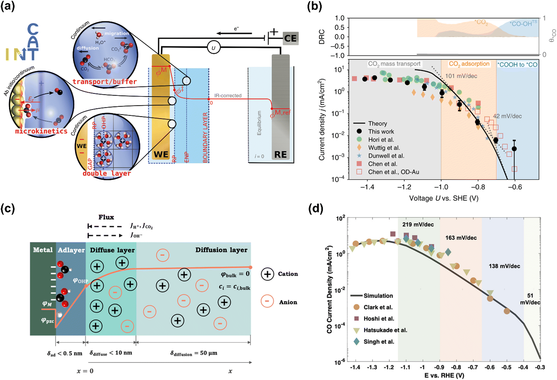 | ||
| Fig. 5 (a) Schematic illustration of the multi-scale system. (b) Multi-scale CO2 electroreduction simulation results over Au compared with experiments. Reproduced with permission.32 Copyright 2020, Nature publishing group. (c) Schematic illustration of the model system. (d) Multi-scale CO2 electroreduction simulation results over Ag compared with experiments. Reproduced with permission.97 Copyright 2021, American Chemical Society. | ||
Similarly, various Tafel slopes were reported over Ag-based electrocatalysts in the literature (No. 6–10) (Table 4). Zhu et al. developed a hierarchical model including intrinsic reaction kinetics, specific surface charging state at a given electrode potential, and mass transport effects to elucidate the reaction mechanism and kinetics of CO2 electroreduction to CO on Ag electrode (No. 8) (Fig. 5c).97 This study highlighted that the local reaction environment could significantly affect the experimental results and perturb the reaction mechanism. The scattered Tafel slopes in the literature were explained to be affected by the surface charging relation and mass transport effects (Fig. 5d). In addition, several reasons were proposed to decrease the reaction rate of CO evolution at high overpotentials, including the decreased CO2 concentration, increased pH, surface charge effects, and lateral interactions between *HCOO, *COOH, and *H. This model well explained the reported Tafel slopes in other studies.110–113 It is worth noting that rigorous analysis of the catalytic activity normalized to the electrochemical surface area (ECSA) likely suggested that nanostructuring does not significantly alter the intrinsic activity of the active sites.114 The as-obtained kinetic observables and reaction rates varied in the literature since they were affected not only by the intrinsic kinetics but also by the local reaction environments.
Additionally, the reaction rate of electrochemical CO2 reduction is significantly affected by the adsorption energies of reaction intermediates,115 which are typically correlated through thermodynamic scaling relations.116 Strategies to break linear scaling relations and regulate reaction pathways are highly desired to tune the activity and selectivity,117–119 for example, introducing additive modifications to electrode surfaces (e.g., molecular complexes or anion species) and alloying multi-metallic electrocatalysts.101,120–125 For example, the Tafel slopes of CN and Cl modified Au electrodes in electrocatalytic CO2 reduction to CO were 45 and 61 mV dec−1, respectively, lower than that of bare Au (ca. 120 mV dec−1), indicating the shifted RDSs in the presence of adsorbed anion (No. 5).98 Peters and co-workers introduced pyridinium-based additives on the PC-Ag surface, which exhibited a lower Tafel slope of 91 mV dec−1 than that of bare PC-Ag, likely due to the suppression of proton but not CO2 mass transport in electrochemical CO evolution (No. 10).99 A similar improvement was reported over ethylenediamine tetramethylenephosphonic acid (EDTMPA) modified Pc-Cu for electrocatalytic CO2 reduction to CH4, where a reduced Tafel slope from 144 to 87 mV dec−1 in the presence of EDTMPA was observed. Breaking linear scaling relations between the two coupled intermediates (*CO and *CHO) was confirmed by Tafel analysis and theoretical calculation of binding energy and free energy change, thus improving the kinetics of CH4 formation.126 In addition, the changed Tafel slopes over alloy electrocatalysts were also demonstrated on Ag and Au-based alloys in electrocatalytic CO2 reduction to CO (No. 11 and No. 12).100,101
For molecular complexes and atomically dispersed electrocatalysts (MNCs), the Tafel analysis is also widely utilized to elucidate their RDSs in electrocatalytic CO2 reduction. For example, the heterogenized CoPc or CoTPP delivered a Tafel slope of 120 mV dec−1 at low overpotential, indicating a slow first electron transfer as the RDS in electrocatalytic CO2 reduction to CO (No. 13 and 14).34,102,127–129 Then, pyridine-functionalized cobalt complexes on a carbon substrate could reduce the Gibbs free energy of CO2 activation further than its counterpart ones and exhibited smaller Tafel slopes, facilitating charge transfer and increasing the activity of CO evolution (No. 15).103 Moreover, Zheng et al. reported that the electronegative N atoms and coordinatively unsaturated Ni–N3 moieties co-anchored carbon nanofiber (Ni–N3-NCNFs) catalyst exhibited the positive effect on facilitating CO2 adsorption and H2O dissociation steps, thus accelerating the reaction kinetics with a lower Tafel slope of 71 mV dec−1 (No. 18).106 The presence of ZrO2 next to the atomically dispersed Ni–N4 sites also could accelerate H2O activation, resulting in a lower Tafel slope (ca. 72 mV dec−1) (No. 17).105
It is worth noting that since the Tafel slope is not sensitive to the variance of the proton donor type, the interpretation of RDS and reaction mechanism still needs more evidence, like other kinetic parameters, operando spectroscopies, or theoretical calculations.
The obvious discrepancies largely arise from the different local reaction microenvironments and misleading interpretations. It is worth noting that the HCO3− can be involved in homogeneous reactions viaeqn (7) and (8) under electrochemical reaction conditions.
| CO2 + OH− ⇄ HCO3− | (7) |
| HCO3− + OH− ⇄ CO32− + H2O | (8) |
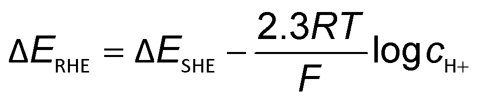 | (9) |
 | ||
| Fig. 6 Bicarbonate order dependence of electrocatalytic CO2 reduction to CO over PC-Ag under fixed ionic strength and at (a) −1.1, −1.2, −1.3 V vs. SHE; (b) at −0.7, −0.8, −0.9 V vs. RHE; and (c) at −1.5 and −1.6 V vs. SHE. (d) Concentration distributions of CO2 in solutions with 0.05, 0.1, and 0.5 M bicarbonate at −1.6 V vs. SHE. Reproduced with permission.97 Copyright 2021, American Chemical Society. | ||
In contrast to low overpotentials, the concentration of bicarbonate varied the CO evolution rate at higher overpotentials. In Fig. 6c, the jCO increased as cHCO3− increased with a positive slope on an even SHE scale and the slope was larger when the overpotential was higher in the presence of mass transportation limitation. This enhancement was ascribed to bicarbonate contributions as buffer species to maintain the local pH and suppress the eqn (7) to consequently enhance the local CO2 concentration, as shown in Fig. 6d.97 Consistently, electrocatalytic CO2 reduction over Co complexes exhibited positive and zeroth orders kinetics on bicarbonate on SHE scale in H-cell102 and gas-fed flow cell (irrespective of overpotential),34 respectively, where mass-transfer limitation was circumvented due to the construction of three-phase interface in gas-fed flow cell under reaction conditions.
Following up on this point, the differences in the local reaction environment can explain the contradicting results of bicarbonate order dependence in the literature. For example, the reported bicarbonate dependences on PC-Ag were 0, and 0.5 in different studies, which were caused by using different potential scales. The first-order dependence on PC Au and Au nanoparticles likely resulted from the combined effects of different potential scales and mass transportation effects. It also should be noted that phosphate was selected to maintain the ionic strength, which may lead to specific adsorption of buffering anions to poison the CO evolution on PC-Au and promote the H2 evolution.33,130 Additionally, some abnormal values appeared when the experiments were conducted in electrolytes containing different cHCO3− with different ionic strength.102,107
3.2 Tafel and reaction order analysis of electrocatalytic CO reduction over Cu
As described in Section 2, CO is a key and necessary intermediate during electrocatalytic CO2 reduction to CH4 and C2+ compounds.57,141 Moreover, CO can alleviate the complexity of the multiple equilibrium reactions between CO2 and aqueous electrolytes. Hence, the development of microkinetic analysis of electrochemical CO reduction has attracted tremendous attention in recent years, which can be extended to the rational design of efficient catalysts in electrocatalytic CO2 reduction. This section reviews the studies on the Tafel and reaction order analysis for electrochemical CO reduction to C2+ and CH4 formation, focusing on the reaction order with respect to PCO (Table 5), where significant effects of reactor configuration on the reaction order measurements will be discussed.A pioneering work was reported by Hori et al. in 1997, which demonstrated the efficient electrochemical CO reduction to CH4 and C2+ on Cu in a H-type Cell and disclosed their molecular-level reaction pathways with regard to microkinetic analysis (No. 22). Their study revealed that the reaction rates of C2H4 and C2H5OH were insensitive to pH of electrolyte, where H2O as the proton source for C2H4 and C2H5OH formation was proposed. In contrast to C2H4 and C2H5OH formation, the reaction rate of CH4 was proportional to proton activity and followed the Tafel relationship. However, their Tafel slopes were abnormal (>118 mV dec−1), likely arising from the mass transportation limitation. The different transfer coefficients (0.35 for C2H4 and 1.33 for CH4) indicated the reaction paths of CH4 and C2H4 formations were separated at an early stage of CO reduction.57 Then, Lu and co-workers examined the rigorous electrokinetic analysis by employing a PTFE modified electrode to reduce the CO mass transport limitation in electrocatalytic CO reduction (No. 24 and 25). Based on the measured Tafel slopes (118 mV dec−1 for both C2+ and each product) and reaction orders with respect to PCO (first-order dependence for C2+ products) at PCO < 60 kPa, they proposed that the formation rates of C2+ products are most likely limited by the hydrogenation of CO with adsorbed water in H-cell.135–137 Moreover, the microkinetic analysis by integrating pH-dependent CH4 formation rate, shifted Tafel slopes at different electrolytes with varied pH, and reaction orders with respect to PCO suggested that the reaction rate of CH4 was limited by the CO hydrogenation step via a PCET in weakly alkaline electrolytes (e.g., 7 < pH < 11) and a chemical hydrogenation step of CO by adsorbed hydrogen atom at pH > 11, respectively.135,136 Additionally, Schreier et al. investigated the dynamics of CO on the Cu surface, providing deeper insight into the mechanism for the production of H2, CH4, and C2H4. It should be noted that these experiments were performed at low temperatures in an ethanol medium (−35 °C) to increase CO solubility and surface-affinity. Those findings showed that the reaction rate of C2H4 was insensitive to PCO, concluding that C2H4 was likely formed via *CO dimerization on a *CO saturated surface; the reaction rate of CH4 was suppressed by increasing PCO, which was interpreted by the competition between *H and *CO on Cu surface to govern the product distributions.142
Recently, Kastlunger et al. experimentally performed the rigorous Tafel analysis at a wide range of pH values (3–13) in conjunction with constant-potential DFT kinetics to analyze the RDS in CO electroreduction on Cu. Their measured current densities were in agreement with the literature data, as shown in Fig. 7.86 The as-obtained partial current densities of C2+ products at pH 3 exhibited slightly decreased due to the specific adsorption of buffering anions (Fig. 7a), which could block active sites and/or compete with CH4 and H2 production.143 The experimentally obtained Tafel slopes of C2+ (Fig. 7a) were consistent with the theoretically derived slopes assuming *CO dimerization as the RDS, where the potential response was considered. Contrary to C2+ formation, the partial current densities of CH4 exhibited pH-dependent activity and did not overlap for these three pH values on the SHE scale, suggesting that the proton donor was different. By analyzing Tafel slopes (ca. 40–90 mV dec−1), at lower pH values of 3 and 7, the first PCET step was proposed as the RDS for CH4 formation; at pH = 13, and the second PCET step was identified as RDS, consistent with Hori's results.54,57
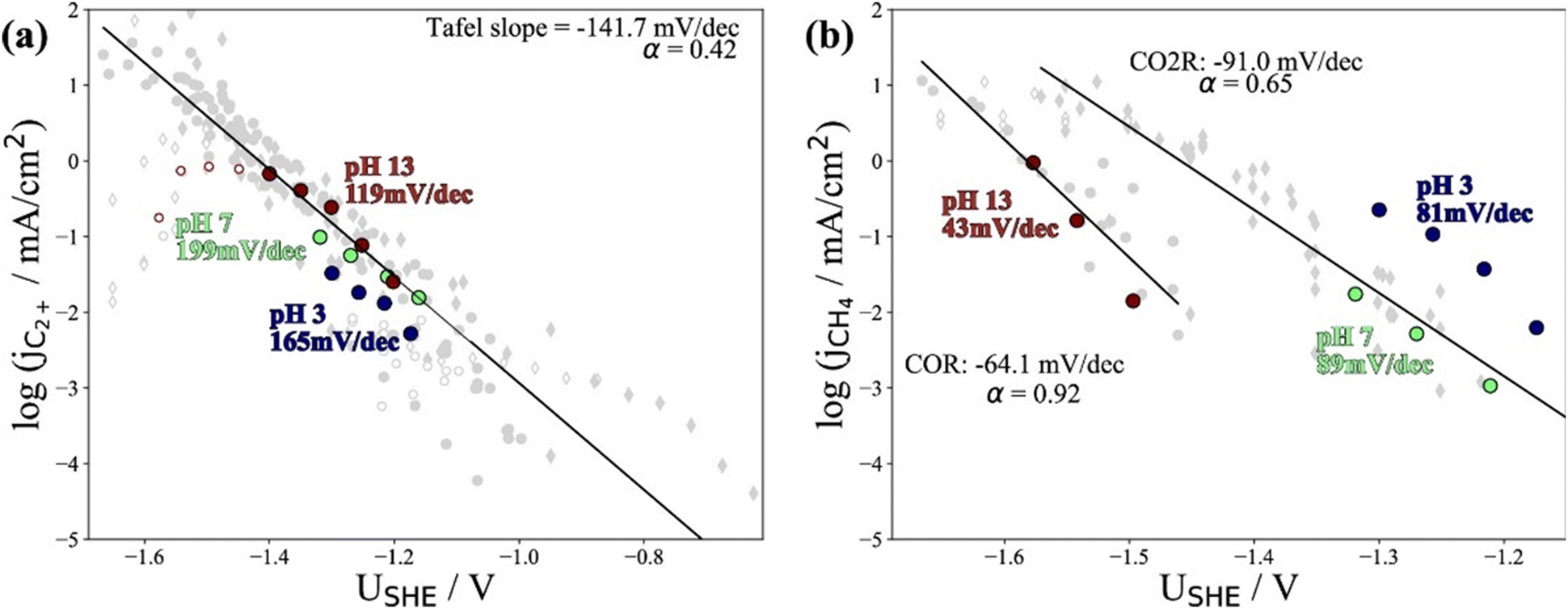 | ||
| Fig. 7 The partial current densities of (a) C2+ products and (b) methane at pH 3, 7, and 13 on PC–Cu foil. Reproduced with permission.86 Copyright 2022, American Chemical Society. | ||
Notwithstanding the conflicting results provided by microkinetic analysis, some proposed RDSs can be excluded easily. For example, the hydrogenation of *CO with H2O136 cannot be the RDS for C2+ formation since the jC2+ were undoubtedly demonstrated to be insensitive to pH at ambient pressure and temperature. Only the Tafel slope of 118 mV dec−1 and the first reaction order with respect to PCO could not yield exclusive RDS in CO electroreduction. For CH4 formation, the findings in ethanol media at low temperatures could not be extended to the aqueous conditions at room temperature, where a negligible *H coverage is expected on Cu since H2 evolution on Cu142 is limited by the Volmer step. In this context, the competition between *H and *CO over Cu for CH4 production seems unlikely in aqueous conditions. Moreover, the chemical hydrogenation step of *CO by *H on Cu at (pH > 11) was also proposed as RDS.136 If so, the current–voltage relationship should overlap on the RHE scale, inconsistent with the experimental results.86 Indeed, a significant influence of the local reaction environment has been emphasized for the catalytic performance evaluation of CO(2) electroreduction.144 The activity and selectivity of electrocatalysts change significantly as a function of reaction rate due to local pH and CO(2) availability. It should be noted that all these studies were performed using a conventional aqueous H-cell, which fails to achieve an industrially relevant reaction rate because of the mass-transport limitations. Consequently, the proposed reaction mechanism may be interpreted wrongly due to the operating conditions.
Accordingly, performing a microkinetic assessment in a cell configuration with improved mass transfer flux is essential to understand and design an electrocatalyst. In recent work, an in-depth microkinetic investigation assessed under commercially relevant conditions was performed over Cu using a gas-fed flow cell.145 Consistently, the reaction rates of C2+ products (e.g., C2H4, C2H5OH, and n-PrOH) over Cu exhibited zeroth orders kinetics on H+ and OH− irrespective of PCO and reactor configuration, indicated that water was used as the proton donor.57,134–136,142 Regarding the effect of PCO, jC2+ increased with increased PCO below about 20.2 kPa with a slope of about 1, while above this partial threshold pressure, the rate remained unchanged, indicating that the formation of C2+ products shared some early intermediates. Moreover, this overall jC2+–PCO relationship was deconvoluted to each product, showing that higher PCO favored n-PrOH and acetate at the expense of C2H4 and C2H5OH. This transition in the reaction orders was not observed in previous studies employing H-cells,57,134–136,142 most likely due to the distinct local reaction environment. The opposite PCO-dependent trends for different C2+ products suggest that the plausible scenario was a shared RDS for all C2+ products. Meanwhile the selectivity-determining steps would result in various apparent reaction orders for different C2+ products. Overall, the electrokinetic results integrating the Tafel slope (ca. 120 mV dec−1), reaction orders concerning pH and PCO, and other kinetic observables suggested that the formation of C2+ was likely limited by the formation of M-CO(H)-CO− species with the surface site predominantly comprising M-CO(H) and the product distribution was perturbed by coverage of *CO as a key intermediate at selectivity-controlling steps after the RDS.145
Regarding the local reaction microenvironment created in different reactor configurations, four aspects must be considered. First, the CO availability on Cu is significantly different in conventional H-type cell and GDE-based electrolyzers. In a H-type cell, CO is supplied to Cu surface that was fully or partially immersed in a liquid electrolyte, while CO could be provided via the gas-phase using a gas-diffusion layer where a gas–liquid–solid interface is constructed. There is a roughly 3-order of magnitude reduction in CO diffusion pathways to the surface of the catalyst: from ca. 50 μm (H-cell) to 50 nm (GDE), resulting in different CO coverage.144 It was reported that the surface coverage of CO on Cu affected the binding energy of CO and reaction intermediates due to adsorbate–adsorbate interactions, especially under higher coverages.146,147 For the chemisorption of CO on Cu(111) at low temperatures, the initial heat of adsorption of 50 kJ mol−1 was maintained up to one-third coverage and then dropped abruptly to 38 kJ mol−1.147,148 Second, local pH near the Cu surface varies significantly at low current density and industrially relevant conditions. Although the overall reaction rate of CO electroreduction showed less dependence on pH, it could result in altered energetics of reaction intermediates or reaction pathways as a function of current density. For example, the partial current density for acetate experienced a significant enhancement at elevated OH− concentration during CO electroreduction.149,150 It was also reported that local pH affected the adsorption configuration of reactants and intermediates (e.g., flat or vertical mode), resulting in different product distributions in electrocatalytic system.151,152 Third, the influence of the potential dependence on the reaction energetics, intermediate adsorption, and reaction pathways should be taken into account. The applied potentials can change the binding enthalpy and entropy of reaction intermediate through electric field effects (e.g., the surface dipole moment or polarizability).153 For example, the previous study revealed that the RDS on gold was *COOH to *CO at low overpotentials and CO2 adsorption at intermediate overpotentials.32 Finally, it should be noted that the solvation effect (e.g., hydrogen bond) and bubble formation could also affect the reaction rates and reaction intermediates.148,154–156 For example, the *COH intermediate could also be stabilized via hydrogen bonding between its OH functional group and a neighboring *CO adsorbate.37
3.3 KIE study in electrochemical CO(2) reduction
The quantification of KIE can provide deeper insight into whether isotopes are involved in the RDS in heterogeneous catalysis (Fig. 8a and b).157 Generally, the elementary steps for electrochemical CO(2) reduction fall into one of the following categories: (1) chemical step, (2) ET, (3) CPET, and (4) PT. When the RDS is CPET, PT, or chemical steps with H-containing species, the presence of isotopes in the electrolyte will vary the reaction rate of electrochemical CO(2) reduction. More specifically, KIE is usually categorized into primary KIE, secondary KIE (Fig. 8c), and inverse KIE (Fig. 8d). The cleavage of bonds containing isotopes causes primary KIE, and its magnitude is related to the difference in zero-point energy (ZPE) between the C–H and C–D bonds (Fig. 8a). The maximum KIE is predicted to be 6.5 when the target bond is 100% split at the transition state. Some experimentally obtained KIEs are lower than 6.5 due to the incomplete cleavage of the target bond or the residual ZPE difference between C–H and C–D bonds at the transition state (Fig. 8b).158–162 Secondary KIE indicates a change in bond hybridizations (e.g., from a sp3 hybridized C atom to a sp2 hybridized C atom) rather than bond cleavage, resulting in a maximum value of approximately 1.41 (Fig. 8c).163,164 On the other hand, a reverse secondary KIE (Fig. 8d) could occur, delivering a maximum value of approximately 0.7 when the C–H bond shows a larger activation energy and a slower reaction rate than the C–D bond.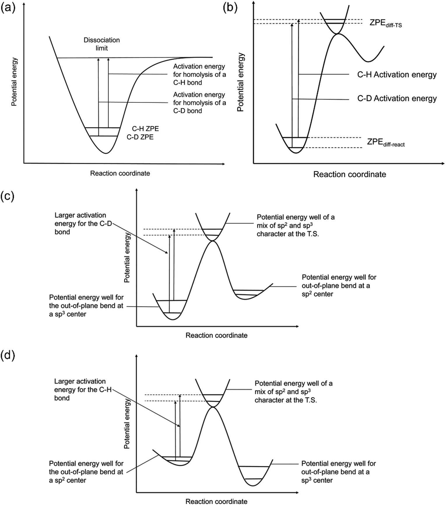 | ||
| Fig. 8 (a) A scheme of KIE in C-H bond activation. (b) A scheme showing the observed KIE related to the residual ZPE. Energy diagrams showing the (c) normal and (d) inverse secondary KIEs. Reproduced with permission.157 Copyright 2020, RSC publication. | ||
In conjunction with the deuterium labeling method, isotope measurements could provide more evidence of the reaction mechanism. For example, Ma et al. examined the isotopic effects over sulfur-doped In catalyst using H-type cell in electrocatalytic CO2 reduction to formate. jHCOO− in K2SO4/H2O was larger than that in the K2SO4/D2O system and the corresponding KIE was around 1.9, consistent with the primary KIE.168 Additionally, almost 98% of the produced formate was in the form of DCOO− when D2O was used to replace H2O in 0.5 M KHCO3 electrolyte, suggesting the origin of H in formate coming from H2O rather than HCO3−. Taken together, these findings revealed that the dissociation of H2O was involved in the RDS for electrochemical CO2 reduction to formate over sulfur-doped In catalyst.169
In electrochemical CO reduction to C2+, Chang et al. performed isotopic effects on PC–Cu in H-type cell. jC2H4 was reduced by a factor of ca. 3.5 by switching the electrolyte from 1.0 M NaOH/H2O to 1.0 M NaOH/D2O, consistent with a primary KIE, concluding that H transfer was involved in the RDS for C2H4 formation.137 However, Lu et al. carried out similar KIE studies on Cu using a gas-fed flow cell and found that jC2H4 in KOH/H2O was indeed larger than that in the KOD/D2O system across the potential window. However the apparent KIE was only around 1.2–1.4, likely consistent with a secondary KIE, indicating a change in bond hybridizations rather than bond formation or cleavage. These results indicate that the decrease in the vibrational frequency after the bond-hybridization for a C–H bond was more significant than that for a C–D bond, leading to smaller activation energy and a faster reaction rate of C2H4 formation. The determined KIE (ca. 5–7) for HER perfectly agree with the literature data, giving audiences confidence in the accurate KIE of C2H4 being measured.137 The difference between as-obtained KIE in the H-type and gas-fed flow cells likely resulted from the local reaction conditions. These finding could not exclude the RDS involved in hydrogen-containing species (e.g., *CO(H)). More evidence from spectroscopic studies and theoretical calculations is needed to interpret the detailed reaction pathways for CO electroreduction.
Isotopic effects have been widely utilized not only in mechanistic studies, but also in the ration design of catalysts. Wang and co-workers studied the isotopic effect on electrocatalytic CO2 reduction to C2H4 over nano-structured Cu using a gas-fed flow cell. The formation rate of C2H4 was suppressed by the replacement of H2O with D2O in 1 M KOH electrolyte, and an apparent KIE of up to ca. 2 was obtained, indicating that the dissociation of H2O was involved in the rate-determining step. Interestingly, halogen (I, Br, Cl, and F)-modified copper catalysts resulted in the decreased KIE, delivering values of 1.8, 1.5, 1.3 and 1.2 over I–Cu, Br–Cu, Cl–Cu and F–Cu catalysts, respectively. The KIE over the F–Cu catalyst close to 1 indicated that the presence of F on copper accelerated H2O activation, which was no longer the rate-determining step over this catalyst.170 Moreover, Guo et al. observed a primary KIE (ca. 2.9) in electrocatalytic CO2 reduction to CO over layered bismuth subcarbonate (Bi2O2CO3; BOC) in a gas-fed flow cell, which indicated that the O–H cleavage of water was involved in the RDS. When Ag was introduced to adjacent Bi sites (Ag/BOC), the corresponding KIE was decreased to ca. 2.5, suggesting that Ag could accelerate the dissociation of H2O to supply reactive hydrogen species to facilitate CO2 hydrogenation to produce formate.171
For heterogeneous molecular catalysts, McCrory and co-workers conducted KIE studies to investigate the influence of axial ligand coordination on CoPc during electrocatalytic CO2 reduction in H-type cells. The parent CoPc exhibited identical KIE in H-based and D-based electrolytes, which was consistent with a rate-determining CO2-coordination step.34 Likewise, the unity of KIE was also observed when the CoPc was immobilized within a non-coordinating poly-2-vinylpyridine polymer (P2VP). On the contrary, the five-coordinate CoPc(py) exhibited a primary KIE of 3.1, indicating a changed RDS involved in proton transfer. Moreover, the primary KIE of ca. 2 was observed on the five-coordinate CoPc(py) immobilized within P2VP and parent CoPc immobilized within the coordinating polymer P4VP, suggesting that the PVP polymers moderated the extent of KIE for the five-coordinate CoPc systems with axially-ligated pyridyls. These findings prove that axial-coordination from the pyridyl moieties in P4VP to CoPc changes the RDS in CO2 electroreduction, resulting in the increased activity.178 Moreover, Guo and co-workers reported a primary KIE of 4 over copolymerization of CoPc supported on CNT in H-type cell in electrocatalytic CO2 reduction to CO, indicating proton transfer was involved in RDS. Further modification with ultrathin conjugated microporous phthalocyanines (Pc) layer (CNT@CMP(H2PCCoPc)) significantly decreased KIE to ca.1.8, signifying that the water dissociation was largely accelerated with the assistance of the H2Pc layer. Interestingly, the as-prepared CNT@CMP(H2PC-CoPc) enabled a maximum of 97% at a current density >200 mA cm−2 at −0.9 V vs. RHE.179 Similar strategies for CoPc were also reported in other studies.128,180
3.4 Temperature-sensitivity analysis of electrochemical CO(2) reduction
Until now, GDE has already been used to increase the current densities of CO(2) reduction to industrially relevant values. However, the energy efficiency of electrochemical reactions (defined by comparing the applied voltage with the thermodynamic voltage) is much worse than the required efficiency. Increasing operating temperature is an effective strategy, which generally results in higher rates and increases the energy efficiency.181–183 However, systematical temperature-sensitivity analysis is rare and the temperature effect in electrocatalytic CO2 reduction is complex, which can affect several reaction parameters, including local pH, the diffusion rate of reactants to the electrode surface, adsorbed intermediates, and solution resistance.Hori et al. investigated the temperature dependent-performance over PC–Cu in electrocatalytic CO2 reduction using a H-type cell, where the catalytic performance was evaluated at a constant current density of 5 mA cm−2. The electrode potential was decreased from −1.39 to −1.33 V vs. SHE with an increase of temperature from 0 to 40 °C. The results showed that CH4 was the dominant product at 0 °C, and its maximum faradaic efficiency (FE) was 60%. With increasing temperatures to 40 °C, the H2 evolution and C2H4 formation dominated the surface reaction and the corresponding FE was 50% for H2 and 20% for C2H4.184 It is noteworthy that the catalytic performance was obtained during the first 15 min. Consistently, Ahn et al. also found that lower temperature (2 °C) favored CH4 formation (ca. 50%) at the expense of C2H4 (only 10%) and H2 evolution dominated the electrochemical reaction in H-type cell, reaching >50% FEH2 at >30 °C at an applied potential of −1.60 V vs. Ag/AgCl. Temperature effects were explained mainly by the changes in CO2 concentration rather than changes in pH.185 However, it was also reported that lower temperature favored CH4 and C2H4 generation over Cu-based catalysts in KOH + methanol due to the higher CO2 solubility.184,186,187
The temperature-sensitivity analysis will be more interesting at commercially-relevant current densities, which can be used for system design. Löwe et al. investigated the temperature dependence on tin oxide loaded GDE in electrocatalytic CO2 reduction to formate. As the temperature increased, the total current density was enhanced (Fig. 9a). Considering the selectivity, the best performance was achieved at a temperature of 50 °C, which allowed a current density of 1000 mA cm−2 with FEHCOO− >80%. Lower or higher operating temperatures both show an increased HER at total current density of 1000 mA cm−2, likely resulting from the opposing influence of temperature on CO2 diffusion coefficients and solubility in the water layer on Cu. Note that electrowetting needs not to be considered when increasing the temperature for electrolysis.188
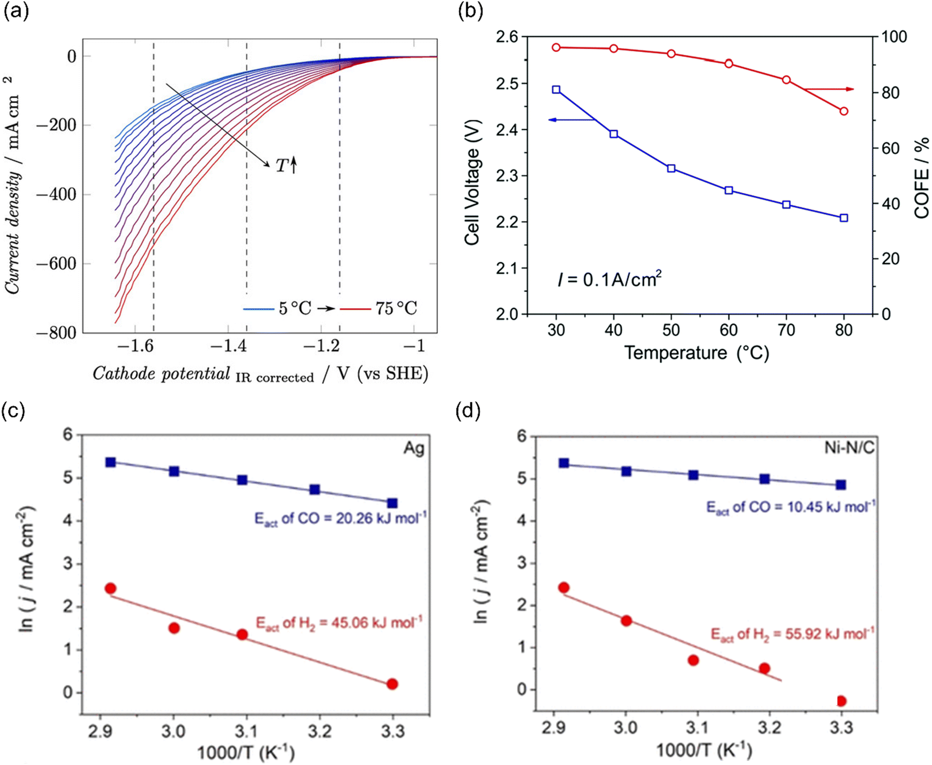 | ||
| Fig. 9 (a) The temperature dependence on GDE of SnOx in a gas-fed flow cell. Reproduced with permission.188 Copyright 2019, Wiley-VCH. (b) The temperature-dependent cell voltage and CO selectivity over Au under a current density of 0.1 A cm−2. Reproduced with permission.189 Copyright 2019, RSC publishing group. The activation energy for CO2 reduction to CO (blue) and the HER (red) on (c) Ag and (d) Ni–N/C electrodes. Reproduced with permission.195 Copyright 2021, American Chemical Society. | ||
In addition, Zhuang and co-workers investigated the temperature-dependent performance of PC-Au and the efficiency of CO2 reduction to CO in an alkaline polymer electrolyte using pure water as the electrolyte. When the operating temperature was increased from 30 °C to 80 °C, the FECO declined from 96% to 72% and the cell voltage decreased from 2.5 V to 2.2 V (Fig. 9b), resulting from the kinetic effects of both the electrode reactions and the ionic conduction.189 Since solution resistance was less than 0.4 Ω cm−2, the corresponding voltage reduction was only 0.04 V. Hence, the improvement mainly comes from the reaction kinetics rather than the ionic conduction. The decline in the FECO upon increased temperature indicated the change in the catalytic selectivity between CO2 reduction and HER. These studies suggest that exploring the optimal operating temperature is essential to increase energy efficiency. Importantly, GDE restructuring and membrane failures were observed at high operating temperatures, leading to severe deactivation of the catalytic systems.190–194
Although the trend of CO2 electroreduction has been examined in some systems, the apparent activation energy (Ea) was rarely calculated, which is a quantitative analysis of temperature effects. Kim et al. examined the temperature-dependent performance from 303 to 343 K over Ag NPs and Ni–N/C separately in a membrane electrode assembly electrolyzer (MEA) and the corresponding Ea of CO2 reduction to CO and HER was calculated. The Ea of HER (45–60 kJ mol−1) was always higher than that of CO evolution (10–20 kJ mol−1) on both electrocatalysts (Fig. 9c and d). Moreover, Ni–N/C delivered a lower Ea of CO evolution (10 kJ mol−1) than Ag NPs (20 kJ mol−1), indicating that CO2 activation was easier than that on Ag.195 Of note, the Ea value was calculated by Arrhenius plots of jCO and jH2 at fixed −2.75 V, where the precise potentials were not well calibrated. In another study using H-type cell equipped with a reference electrode, the Ea of CO2 reduction to CO over Ag NPs was 72 kJ mol−1, much higher than that in MEA. Moreover, they found that different nano-structured Ag delivered different Ea values, where 44 kJ mol−1 and 21 kJ mol−1 were extracted for Ag rods and needles, respectively. These differences likely come from the local reaction environment and the calibration of applied potentials.
Koper and co-workers examined the temperature effects on rotating ring gold disk electrode in cation-promoted CO2 reduction, disclosing that both activity and selectivity of CO2 reduction to CO increased with temperature. However, the enhancement of kinetics of CO evolution was counteracted by the lower CO2 solubility, which yielded an optimized working temperature of ca. 55 °C. The apparent activation energy was obtained to be 61 kJ mol−1 in 0.1 M NaHCO3, whose value decreased with cation concentration and identity. In addition, the transfer coefficient was also derived to be ca. 0.3, which indicated that the enthalpy contribution played a dominant role in this process and entropy was non-negligible.196
Recently, Lu et al. investigated the temperature-sensitivity analysis of electrochemical CO reduction on Cu in a gas-fed flow cell equipped with a well-defined reference electrode, revealing a pronounced influence on the catalytic activity of CO reduction at increased temperatures. The calculated Ea values for all C2+ products fall within 60 ± 12 kJ mol−1, comparable to the reported theoretical value for the C–C coupling process of 30–75 kJ mol−1.154 It should be explicitly noted that the Ea value for each product did not have to reflect the (apparent) activation energy of the RDS, especially when the RDS followed selectivity-determining steps. Likewise, in reaction order analysis, various Ea values for each product were obtained, although they shared with a common RDS because the product distribution was perturbed by CO coverage as a key intermediate at selectivity-controlling steps after the RDS.
4. Challenges and limitations of microkinetic analysis in electrocatalytic CO(2) reduction
4.1 The existing challenges in microkinetic analysis
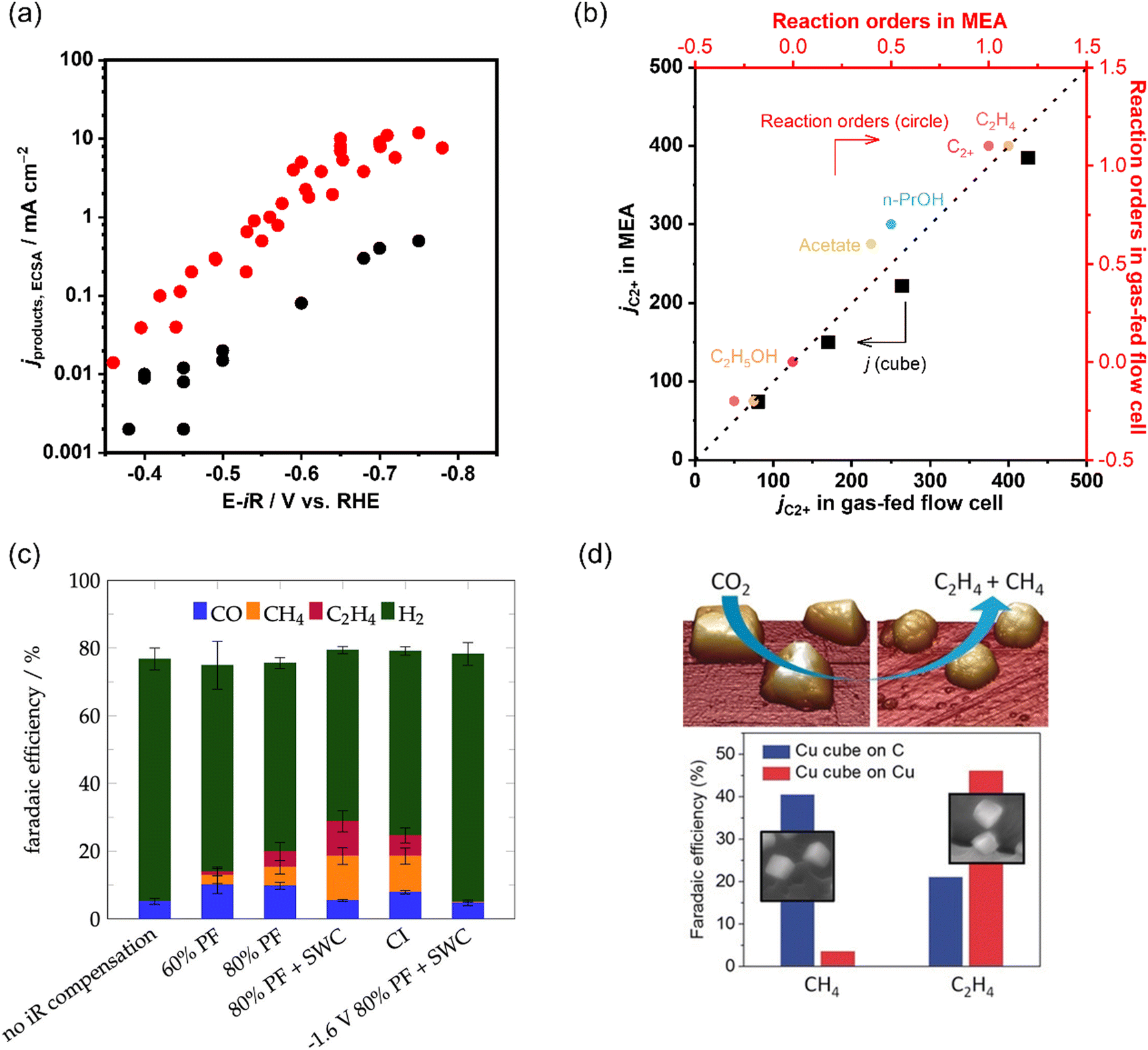 | ||
| Fig. 10 (a) Comparison of C2+ partial current densities normalized to ECSA of CO electroreduction on Cu in a gas-fed flow cell and H-type cell. The data is adapted from ref. 145, 149, 150, 199, 200 (b) Comparison of as-obtained kinetic results (jC2+ and reaction orders) in a gas-fed flow cell and MEA under the same reaction conditions during CO electroreduction over Cu. The data is adapted from ref. 145. (c) Product distributions with different iR compensations at −1.7 V vs. Ag|AgCl in CO2 saturated 0.1 M KHCO3. Reproduced with permission.204 Copyright 2022, American Chemical Society. (d) Dynamic changes in the structure and catalytic selectivity of Cu nanocubes in CO2 electroreduction. Reproduced with permission.205 Copyright 2018, Wiley-VCH. | ||
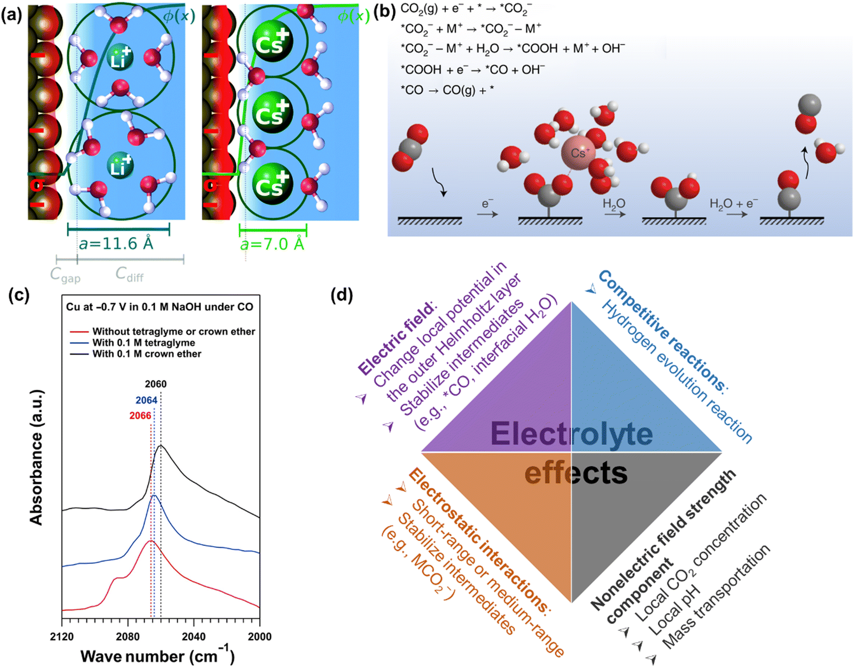 | ||
| Fig. 11 (a) Illustration of the origin of cation effects in field-driven electrocatalysis. Reproduced with permission.131 Copyright 2019, RSC publishing group. (b) Schematic representation of the interaction of the cation with the negatively charged CO2− intermediate together with a proposed reaction mechanism. Reproduced with permission.221 Copyright 2021, nature publishing group. (c) The impact of organics on attenuated total reflection surface-enhanced infrared absorption spectroscopy.133 (d) Summary of electrolyte effects on electrochemical CO2 reduction. | ||
Furthermore, the nature and concentration of anions also influence the performance by their effects on the competing HER, especially in the presence of mass-transportation conditions.223–226 Since the different branches of HER (e.g., proton, buffer mediated species, or water reduction) on electrocatalysts could occur depending on the local reaction microenvironments including applied potentials, the concentration of electrolyte, and CO(2) concentration. For more detailed reviews of electrolyte effects on CO2 electrochemical reduction, the reader is referred to specialized recent reviews.222
Overall, the last decades have witnessed intensive research efforts dedicated to the exploration of electrolyte effects on CO(2) reduction, as illustrated in Fig. 11d. Nevertheless, their main role (especially cation) is still under discussion. For example, Li et al. revealed that a small change in interfacial electric field strength was not likely the main contribution to the as-obtained difference in the performance of CO reduction, where the varying interaction between adsorbed CO and interfacial water was interpreted to change performance in presence of different organic cations.227 Similarly, Xu and co-workers reported that the cation concentration (e.g., 0.1 M or 1 M Na+) and cation identity (e.g., K+, Rb+, Cs+) during CO reduction did not change the Stark tuning rate or the interfacial electric field strength;133,220 on the contrary, they significantly changed the catalytic performance. Then, nonelectric field strength components of the cation effect were proposed to affect CO dimerization.133 However, the definitive evidence of nonelectric field strength components is still missing. Thus, systematic studies of the cation effects on CO(2) reduction and the correspondingly quantitative expression in kinetic equations are necessary for further study.
4.2 Limitations of the microkinetic analysis
≈ 0 or ≈1) is generally assumed, although, in practice, the slopes are coverage dependent. For example, it is widely accepted that the Tafel slopes of 120, 40, and 30 mV dec−1 are observed for the Volmer, Heyrovsky, and Tafel determining rate steps, respectively, during HER. However, for the Heyrovsky rate-determining step, a Tafel slope of 120 mV dec−1 was observed in the higher adsorbed hydrogen atom coverage (θH > 0.6). Similarly, the Tafel slope of CO2 electroreduction toward CO could be simplified to eqn (10), when a3 is assumed to be RDS.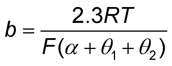 | (10) |
In addition, reaction order is also coverage dependent. For example, it has been demonstrated that the coverage of the intermediates was changing based on the applied potentials in CO electro-oxidation, resulting in the changed reaction orders along with the applied potentials. Therefore, it is challenging to use only the Tafel slope and reaction order to affirm or exclude a proposed mechanism without any information on the coverage of intermediates under operating conditions in electrocatalytic CO(2) reduction.
To understand the coverage of intermediates, future work involving surface-sensitive spectroscopies mirroring GDE based-conditions is needed. For example, Lu and co-workers developed a custom-designed spectra-electrochemical cell allowing CO pressures up to 6 MPa to investigate surface enhanced infrared spectroscopy over PC–Cu in electrocatalytic CO reduction. They found the upper bound of the CO coverage under electrocatalytic conditions to be 0.05 monolayer at atmospheric pressure and the saturation CO coverage to be ∼0.25 monolayer.139 Apart from operando spectroscopies, DFT is another convenient and powerful tool to understand the adsorption isotherm for relevant adsorbates and thermodynamic parameters related to the adsorption equilibrium constant.
It is also worth mentioning that the effect of the applied potential on the free energy of intermediates is important since the enthalpy and entropy of intermediates are potential-dependent in many cases.153 Wang and co-workers developed a continuous-flow Raman electrochemical cell for electrocatalytic CO2 reduction, which enabled to monitor the local pH variation near the surface of GDE under reaction conditions,228 verifying the presence of the apparent overpotential reduction on the RHE scale in alkaline electrolyte due to the Nernst potential of the strong pH gradient layer at the cathode/electrolyte interface. This change in the electric fields can significantly alter the binding energies of intermediates and solvent molecules at the electrode/electrolyte interface. In addition, the adsorption energy of intermediates can also be affected by the coverages of adsorbates on the surface.
Overall, the coverage of various intermediates should not be overlooked in both the Tafel slope and apparent reaction order analysis, where the electric field effects and adsorbate–adsorbate interactions may be necessary to consider.
 | (11) |
 | (12) |
An additional assumption in microkinetic analysis pertains to the quasi-equilibrium, where the reactions are assumed to occur rapidly in both forward and reverse directions before the RDS step. Actually, the non-rate-determining step can be nonequilibrium. In oxygen evolution reaction, Marshall et al. have demonstrated that models using the quasi-equilibrium assumption fail to predict some Tafel regions.233 Hence, the steady-state assumption is recommended for predicting Tafel slopes.
5. Conclusion and outlook
Microkinetic studies are powerful tools in electrocatalytic CO(2) reduction, helping to identify critical reaction intermediates and RDSs. This information is crucial for designing improved electrocatalysts and scaling up CO(2) electrochemical reactors. This review systematically summarizes DFT-based microkinetic models for various products (e.g., CO, HCOOH, CH4, and C2+) and numerous experimentally-derived kinetic observables associated with the complex processes occurring in electrocatalytic CO(2) reduction. Although Tafel and reaction order analyses, combined with KIE and temperature sensitivity analyses, are widely used to gain mechanistic insights, the kinetic observables obtained under incorrect operating conditions or oversimplified models often fail to accurately describe surface electrocatalysis. The experimentally scattered results have been systematically analyzed, and the effect of the local reaction microenvironment on the obtained kinetic observables has been highlighted. Moreover, the challenges in intrinsic kinetic measurements and the limitations of microkinetic analysis are carefully discussed.With these challenges and limitations in mind, we now consider the opportunities for more effectively using microkinetic analysis to understand the reaction mechanism. The detailed strategies are as follows:
(1) Accurate interpretation of catalytic performance
Selecting well-defined electrodes, suitable experimental conditions, and reactor configurations is critical for intrinsic kinetic measurements, where the measured rates are governed by kinetics rather than being convoluted by mass transport limitations. And no mass transport limitation in the system and potential/time-independent electrodes are required. In this context, the rotating ring disk electrode (RRDE) is a potential candidate to extract the true intrinsic kinetics of electrocatalysts, which has been successfully demonstrated to control and improve mass transport for oxygen reduction reaction. For CO2 reduction to CO, Koper and coworkers have utilized RRDE to perform microkinetic analysis over Au in various electrolytes under well-defined mass transport conditions and using online analytical techniques.71,222–224 In further work, the well-defined RRDE equipped with online product identification (e.g., H2, HCOO−, CH4, C2+) and quantification techniques with high resolution will be the next system challenges. Alternatively, the exploration of well-defined electrodes with the gas-diffusion layer will be another direction, which allow for higher current densities. Accordingly, the commonly used online analytical techniques can be used. It should be noted that this configuration absolutely will introduce non-kinetic effects including the complexities of electrode/electrolyte interfaces and diffusion processes of liquid and gas, where it needs more efforts to quantitatively describe their corresponding contributions to the as-obtained catalytic performance. Moreover, as Koper and co-workers recommended in the rigorous Tafel analysis of oxygen evolution reaction, Tafel slopes should be plotted versus current densities or applied potentials to yield a kinetically meaningful Tafel slope value, which was obtained from a horizontal Tafel slope region.246In addition, special care is also needed that catalytic performance of electrocatalyst material will be assessed at commercially relevant current densities, not only substantially lower ones since it is strongly influenced by not only the identity of the electrocatalyst materials but also the local steady-state environment perturbed by reaction micro-environment and the operating current density. Apparent kinetic parameters are necessary to be utilized to establish the relationship between the intrinsic kinetics and “apparent kinetics” at commercially-relevant conditions, which could accelerate the technology toward large-scale CO(2) reduction. Consequently, the GDE with a well-defined reference electrode is needed to alleviate mass transport limitations and record the actual applied potentials. It should be mentioned that the stability of electrocatalysts during electrolysis is of great importance. Electrocatalysts with structural simplicity, ease of handling, and robustness are particularly attractive for fundamental kinetic studies. To enhance stability, one recent example involves placing an inactive material atop the catalyst layer as a current collector, preventing both catalyst restructuring and deposition of contaminants on the active catalyst surface.247 Finally, accurate and precise reporting for electrochemical CO2 reduction studies is essential. For instance, iR compensation should be carefully corrected, and the measured rates should be normalized to the geometric electrode area as well as the ECSA. For further details on standards and protocols for data acquisition and reporting, readers are referred to previous studies.114,248
(2) Utilizing operando spectroscopies as complementary tools
Due to the complexities and uncertainties of microkinetic analysis, it remains challenging to rely solely on microkinetic models to fully uncover reaction mechanisms. Operando spectroscopies can be employed as complementary tools to increase reliability, such as attenuated total reflection surface-enhanced infrared spectroscopy (ATR-SEIRAS),136,137,139 operando Raman spectroscopy,249–251 ambient-pressure X-ray photoelectron spectroscopy,252 and differential electrochemical mass spectroscopy.253 In particular, in situ/operando techniques with high resolution in the time frame of below second is helpful to capture the short-lifetime intermediate. In addition, surface-sensitive spectroscopies that mirror GDE based-conditions (at high rates) are highly desirable, requiring a careful design and fabrication of dedicated devices.(3) Improving DFT-based microkinetic simulation
Significant process in DFT calculations has been made in recent years. Electrochemical activation barriers and potential contributions from electric fields and solvation effects are now considered in microkinetic modeling to enhance computational accuracy. However, an additional constraint stemming from DFT relates to the assumptions of the microkinetic model itself, such as the quasi-equilibrium assumption and random distribution of adsorbed species on the catalytic surface in mean-field models.12,233 As discussed, oversimplified assumptions can lead to misleading conclusions about reaction mechanisms. Therefore, the steady-state assumption is recommended. Several non-idealities should be addressed in future microkinetic modeling, including interfacial structures, solvent dynamics, potential-dependent symmetry factors, potential-dependent intermediate coverage, and adsorbate–adsorbate interactions.(4) Strengthening the connection between DFT and experiments
Strengthening the connection between DFT and experiments is crucial for accurately understanding the mechanistic details of electrocatalytic CO(2) reduction and designing novel electrocatalysts,25,254 which could accelerate the data-driven screen and design of electrocatalysts. Accordingly, the iterative model refinement can be employed as a general methodology. First, the establishment of a model system is an important part of DFT calculation where the correspondingly active site is needed to construct based on fundamental physical and chemical characterizations, but also the electrochemical microenvironment around active sites as well as electrode potential is crucial to be considered. To reduce the complexity in formulating electrochemical processes, single-crystal materials76,196,221–223,226,255 and surface-immobilized single-site catalysts256,257 are highly recommended. Second, kinetic observables are extracted from experiments without mass transport limitation to optimize DFT-based parameters and achieve consistency between computation and experiments. Finally, the feedback gained from the parameter adjustment process is used to revise the original hypothesis for the reaction mechanism and iterate all steps until consistency between experiments and computation is achieved, thereby accurately describing the nature of electrocatalysts.Conflicts of interest
There are no conflicts to declare.Acknowledgements
Asahi Kasei Corporation financially supported this work.References
- I. E. Stephens, K. Chan, A. Bagger, S. W. Boettcher, J. Bonin, E. Boutin, A. K. Buckley, R. Buonsanti, E. R. Cave and X. Chang, J. Phys.: Energy, 2022, 4, 042003 Search PubMed.
- H. Shin, K. U. Hansen and F. Jiao, Nat. Sustain., 2021, 4, 911–919 CrossRef.
- P. De Luna, C. Hahn, D. Higgins, S. A. Jaffer, T. F. Jaramillo and E. H. Sargent, Science, 2019, 364, eaav3506 CrossRef CAS PubMed.
- S. Nitopi, E. Bertheussen, S. B. Scott, X. Y. Liu, A. K. Engstfeld, S. Horch, B. Seger, I. E. L. Stephens, K. Chan, C. Hahn, J. K. Norskov, T. F. Jaramillo and I. Chorkendorff, Chem. Rev., 2019, 119, 7610–7672 CrossRef CAS PubMed.
- Y. Y. Birdja, E. Pérez-Gallent, M. C. Figueiredo, A. J. Göttle, F. Calle-Vallejo and M. T. M. Koper, Nat. Energy, 2019, 4, 732–745 CrossRef CAS.
- D. H. Nam, P. De Luna, A. Rosas-Hernandez, A. Thevenon, F. W. Li, T. Agapie, J. C. Peters, O. Shekhah, M. Eddaoudi and E. H. Sargent, Nat. Mater., 2020, 19, 266–276 CrossRef CAS PubMed.
- J. Resasco and A. T. Bell, Trends Chem., 2020, 2, 825–836 CrossRef CAS.
- J. A. Rabinowitz and M. W. Kanan, Nat. Commun., 2020, 11, 5231 CrossRef CAS PubMed.
- A. Ozden, Y. H. Wang, F. W. Li, M. C. Luo, J. Sisler, A. Thevenon, A. Rosas-Hernandez, T. Burdyny, Y. W. Lum, H. Yadegari, T. Agapie, J. C. Peters, E. H. Sargent and D. Sinton, Joule, 2021, 5, 706–719 CrossRef CAS.
- T. Alerte, J. P. Edwards, C. M. Gabardo, C. P. O'Brien, A. Gaona, J. Wicks, A. Obradovi, A. Sarkar, S. A. Jaffer, H. L. MacLean, D. Sinton and E. H. Sargent, ACS Energy Lett., 2021, 6, 4405–4412 CrossRef CAS.
- O. S. Bushuyev, P. De Luna, C. T. Dinh, L. Tao, G. Saur, J. van de Lagemaat, S. O. Kelley and E. H. Sargent, Joule, 2018, 2, 825–832 CrossRef CAS.
- A. Baz, S. T. Dix, A. Holewinski and S. Linic, J. Catal., 2021, 404, 864–872 CrossRef CAS.
- A. T. Marshall, Curr. Opin. Electrochem., 2018, 7, 75–80 CrossRef CAS.
- G. A. Cerrón-Calle, T. P. Senftle and S. Garcia-Segura, Curr. Opin. Electrochem., 2022, 101062 CrossRef.
- T. Shinagawa, A. T. Garcia-Esparza and K. Takanabe, Sci. Rep., 2015, 5, 1–21 Search PubMed.
- S.-Q. Xiang, S.-T. Gao, J.-L. Shi, W. Zhang and L.-B. Zhao, J. Catal., 2021, 393, 11–19 CrossRef CAS.
- Q. Li, Y. Ouyang, S. Lu, X. Bai, Y. Zhang, L. Shi, C. Ling and J. Wang, Chem. Commun., 2020, 56, 9937–9949 RSC.
- J. T. Mefford, Z. Zhao, M. Bajdich and W. C. Chueh, Energy Environ. Sci., 2020, 13, 622–634 RSC.
- G. O. Larrazábal, A. J. Martín and J. Perez-Ramirez, J. Phys. Chem. Lett., 2017, 8, 3933–3944 CrossRef PubMed.
- Q. Lu and F. Jiao, Nano Energy, 2016, 29, 439–456 CrossRef CAS.
- F. Dattila, R. R. Seemakurthi, Y. Zhou and N. López, Chem. Rev., 2022, 122, 11085–11130 CrossRef CAS PubMed.
- M. R. Singh, J. D. Goodpaster, A. Z. Weber, M. Head-Gordon and A. T. Bell, Proc. Natl. Acad. Sci. U. S. A., 2017, 114, E8812–E8821 CrossRef CAS PubMed.
- A. Bagger, W. Ju, A. S. Varela, P. Strasser and J. Rossmeisl, Chem. Phys. Chem., 2017, 18, 3266–3273 CrossRef CAS PubMed.
- M. Zhong, K. Tran, Y. M. Min, C. H. Wang, Z. Y. Wang, C. T. Dinh, P. De Luna, Z. Q. Yu, A. S. Rasouli, P. Brodersen, S. Sun, O. Voznyy, C. S. Tan, M. Askerka, F. L. Che, M. Liu, A. Seifitokaldani, Y. J. Pang, S. C. Lo, A. Ip, Z. Ulissi and E. H. Sargent, Nature, 2020, 581, 178–183 CrossRef CAS PubMed.
- J. Resasco, F. Abild-Pedersen, C. Hahn, Z. Bao, M. Koper and T. F. Jaramillo, Nat. Catal., 2022, 5, 374–381 CrossRef.
- M. Dunwell, W. Luc, Y. Yan, F. Jiao and B. Xu, ACS Catal., 2018, 8, 8121–8129 CrossRef CAS.
- C. W. Lee, N. H. Cho, S. W. Im, M. S. Jee, Y. J. Hwang, B. K. Min and K. T. Nam, J. Mater. Chem. A, 2018, 6, 14043–14057 RSC.
- T. Shinagawa, A. T. Garcia-Esparza and K. Takanabe, Sci. Rep., 2015, 5, 13801 CrossRef PubMed.
- Y.-H. Fang and Z.-P. Liu, ACS Catal., 2014, 4, 4364–4376 CrossRef CAS.
- S. Fletcher, J. Solid State Electrochem., 2009, 13, 537–549 CrossRef CAS.
- J. Rosen, G. S. Hutchings, Q. Lu, S. Rivera, Y. Zhou, D. G. Vlachos and F. Jiao, ACS Catal., 2015, 5, 4293–4299 CrossRef CAS.
- S. Ringe, C. G. Morales-Guio, L. D. Chen, M. Fields, T. F. Jaramillo, C. Hahn and K. Chan, Nat. Commun., 2020, 11, 33 CrossRef CAS PubMed.
- M. Dunwell, Q. Lu, J. M. Heyes, J. Rosen, J. G. Chen, Y. Yan, F. Jiao and B. Xu, J. Am. Chem. Soc., 2017, 139, 3774–3783 CrossRef CAS PubMed.
- X. Lu, B. Dereli, T. Shinagawa, M. Eddaoudi, L. Cavallo and K. Takanabe, Chem Catal., 2022, 2, 1143–1162 CrossRef CAS.
- A. Wuttig, M. Yaguchi, K. Motobayashi, M. Osawa and Y. Surendranath, Proc. Natl. Acad. Sci. U. S. A., 2016, 113, E4585–E4593 CrossRef CAS PubMed.
- B. A. Zhang, T. Ozel, J. S. Elias, C. Costentin and D. G. Nocera, ACS Central Sci., 2019, 5, 1097–1105 CrossRef CAS PubMed.
- L. D. Chen, M. Urushihara, K. Chan and J. K. Nørskov, ACS Catal., 2016, 6, 7133–7139 CrossRef CAS.
- M. R. Singh, J. D. Goodpaster, A. Z. Weber, M. Head-Gordon and A. T. Bell, Proc. Natl. Acad. Sci. U. S. A., 2017, 114, E8812–E8821 CrossRef CAS PubMed.
- N. Gupta, M. Gattrell and B. MacDougall, J. Appl. Electrochem., 2006, 36, 161–172 CrossRef CAS.
- A. S. Varela, M. Kroschel, T. Reier and P. Strasser, Catal. Today, 2016, 260, 8–13 CrossRef CAS.
- M. Dunwell, X. Yang, B. P. Setzler, J. Anibal, Y. Yan and B. Xu, ACS Catal., 2018, 8, 3999–4008 CrossRef CAS.
- J. Ryu, A. Wuttig and Y. Surendranath, Angew. Chem., Int. Ed., 2018, 57, 9300–9304 CrossRef CAS PubMed.
- Z. Mao and C. T. Campbell, J. Catal., 2020, 381, 53–62 CrossRef CAS.
- H. Prats and K. Chan, Phys. Chem. Chem. Phys., 2021, 23, 27150–27158 RSC.
- X. Chang, S. Vijay, Y. Zhao, N. J. Oliveira, K. Chan and B. Xu, Nat. Commun., 2022, 13, 2656 CrossRef CAS PubMed.
- X. Song, L. Xu, X. Sun and B. Han, Sci. Chin. Chem., 2023, 66, 315–323 CrossRef CAS.
- B. Hasa, Y. Zhao and F. Jiao, Annu. Rev. Chem. Biomol. Eng., 2023 DOI:10.1146/annurev-chembioeng-101121-071735.
- E. Pérez-Gallent, M. C. Figueiredo, F. Calle-Vallejo and M. T. M. Koper, Angew. Chem., Int. Ed., 2017, 56, 3621–3624 CrossRef PubMed.
- I. V. Chernyshova, P. Somasundaran and S. Ponnurangam, Proc. Natl. Acad. Sci. U. S. A., 2018, 115, E9261–E9270 CrossRef CAS PubMed.
- J. Gao, H. Zhang, X. Guo, J. Luo, S. M. Zakeeruddin, D. Ren and M. Grätzel, J. Am. Chem. Soc., 2019, 141, 18704–18714 CrossRef CAS PubMed.
- P. Wei, D. Gao, T. Liu, H. Li, J. Sang, C. Wang, R. Cai, G. Wang and X. Bao, Nat. Nanotechnol., 2023, 1–8 Search PubMed.
- N. J. Firet and W. A. Smith, ACS Catal., 2017, 7, 606–612 CrossRef CAS.
- Y. Hori, H. Wakebe, T. Tsukamoto and O. Koga, Electrochim. Acta, 1994, 39, 1833–1839 CrossRef CAS.
- Y. I. Hori, Mod. Aspects Electrochem., 2008, 89–189 CAS.
- Y. Hori, I. Takahashi, O. Koga and N. Hoshi, J. Mol. Catal. A: Chem., 2003, 199, 39–47 CrossRef CAS.
- Y. Hori, I. Takahashi, O. Koga and N. Hoshi, J. Phys. Chem. B, 2002, 106, 15–17 CrossRef CAS.
- Y. Hori, R. Takahashi, Y. Yoshinami and A. Murata, J. Phys. Chem. B, 1997, 101, 7075–7081 CrossRef CAS.
- D. Xu, Y. Xu, H. Wang and X. Qiu, Chem. Commun., 2022, 58, 3007–3010 RSC.
- Z. Bitar, A. Fecant, E. Trela-Baudot, S. Chardon-Noblat and D. Pasquier, Appl. Catal., B, 2016, 189, 172–180 CrossRef CAS.
- H. Wu, Z. Li, Y. Liu, X. Zou, L. Yin and S. Lin, Sustainable Energy Fuels, 2021, 5, 5798–5803 RSC.
- E. Nurlaela, T. Shinagawa, M. Qureshi, D. S. Dhawale and K. Takanabe, ACS Catal., 2016, 6, 1713–1722 CrossRef CAS.
- S. Rasul, D. H. Anjum, A. Jedidi, Y. Minenkov, L. Cavallo and K. Takanabe, Angew. Chem., Int. Ed., 2015, 54, 2146–2150 CrossRef CAS PubMed.
- M. Liu, Y. Pang, B. Zhang, P. De Luna, O. Voznyy, J. Xu, X. Zheng, C. T. Dinh, F. Fan and C. Cao, Nature, 2016, 537, 382–386 CrossRef CAS PubMed.
- S. Verma, Y. Hamasaki, C. Kim, W. Huang, S. Lu, H.-R. M. Jhong, A. A. Gewirth, T. Fujigaya, N. Nakashima and P. J. A. Kenis, ACS Energy Lett., 2018, 3, 193–198 CrossRef CAS.
- J. Li, I. Maresi, Y. Lum and J. W. Ager, J. Chem. Phys., 2021, 155, 164701 CrossRef CAS PubMed.
- S. Hanselman, M. T. Koper and F. Calle-Vallejo, ACS Energy Lett., 2018, 3, 1062–1067 CrossRef CAS.
- F. Calle-Vallejo and M. T. M. Koper, Angew. Chem., Int. Ed., 2013, 52, 7282–7285 CrossRef CAS PubMed.
- K. J. P. Schouten, Y. Kwon, C. J. M. Van der Ham, Z. Qin and M. T. M. Koper, Chem. Sci., 2011, 2, 1902–1909 RSC.
- X. Liu, J. Xiao, H. Peng, X. Hong, K. Chan and J. K. Nørskov, Nat. Commun., 2017, 8, 1–7 Search PubMed.
- X. Y. Liu, P. Schlexer, J. P. Xiao, Y. F. Ji, L. Wang, R. B. Sandberg, M. Tang, K. S. Brown, H. J. Peng, S. Ringe, C. Hahn, T. F. Jaramillo, J. K. Norskov and K. R. Chan, Nat. Commun., 2019, 10, 32 CrossRef CAS PubMed.
- M. T. M. Koper, A. Z. Weber, K. Chan and J. Cheng, Chem. Rev., 2022, 122, 10579–10580 CrossRef CAS PubMed.
- H. H. Heenen, J. A. Gauthier, H. H. Kristoffersen, T. Ludwig and K. Chan, J. Chem. Phys., 2020, 152, 144703 CrossRef CAS.
- S. Vijay, W. Ju, S. Brückner, S.-C. Tsang, P. Strasser and K. Chan, Nat. Catal., 2021, 4, 1024–1031 CrossRef CAS.
- J. T. Feaster, C. Shi, E. R. Cave, T. Hatsukade, D. N. Abram, K. P. Kuhl, C. Hahn, J. K. Nørskov and T. F. Jaramillo, ACS Catal., 2017, 7, 4822–4827 CrossRef CAS.
- M. T. Tang, H. Peng, P. S. Lamoureux, M. Bajdich and F. Abild-Pedersen, Appl. Catal., B, 2020, 279, 119384 CrossRef CAS.
- A. J. Göttle and M. T. M. Koper, J. Am. Chem. Soc., 2018, 140, 4826–4834 CrossRef PubMed.
- X. Min and M. W. Kanan, J. Am. Chem. Soc., 2015, 137, 4701–4708 CrossRef CAS PubMed.
- K. M. Waldie, F. M. Brunner and C. P. Kubiak, ACS Sustainable Chem. Eng., 2018, 6, 6841–6848 CrossRef CAS.
- Y. Y. Birdja, J. Shen and M. T. M. Koper, Catal. Today, 2017, 288, 37–47 CrossRef CAS.
- C. Ye, S. J. Raaijman, X. Chen and M. T. M. Koper, ACS Appl. Mater. Inter., 2022, 14, 45263–45271 CrossRef CAS PubMed.
- O. Koga, T. Matsuo, H. Yamazaki and Y. Hori, Advances in Chemical Conversions for Mitigating Carbon Dioxide, 1998, vol. 114, pp. 569–572 Search PubMed.
- X. Liu, J. Xiao, H. Peng, X. Hong, K. Chan and J. K. Nørskov, Nat. Commun., 2017, 8, 15438 CrossRef CAS PubMed.
- J. D. Goodpaster, A. T. Bell and M. Head-Gordon, J. Phys. Chem. Lett., 2016, 7, 1471–1477 CrossRef CAS PubMed.
- H. Peng, M. T. Tang, X. Liu, P. Schlexer Lamoureux, M. Bajdich and F. Abild-Pedersen, Energy Environ. Sci., 2021, 14, 473–482 RSC.
- H. Xiao, T. Cheng, W. A. Goddard, III and R. Sundararaman, J. Am. Chem. Soc., 2016, 138, 483–486 CrossRef CAS PubMed.
- G. Kastlunger, L. Wang, N. Govindarajan, H. H. Heenen, S. Ringe, T. Jaramillo, C. Hahn and K. Chan, ACS Catal., 2022, 12, 4344–4357 CrossRef CAS.
- X. Liu, P. Schlexer, J. Xiao, Y. Ji, L. Wang, R. B. Sandberg, M. Tang, K. S. Brown, H. Peng, S. Ringe, C. Hahn, T. F. Jaramillo, J. K. Nørskov and K. Chan, Nat. Commun., 2019, 10, 32 CrossRef CAS PubMed.
- A. J. Bard, L. R. Faulkner and H. S. White, Electrochemical methods: fundamentals and applications, John Wiley & Sons, 2022 Search PubMed.
- A. Baz and A. Holewinski, J. Catal., 2021, 397, 233–244 CrossRef CAS.
- C. T. Campbell, J. Catal., 2001, 204, 520–524 CrossRef CAS.
- C. T. Campbell, ACS Catal., 2017, 7, 2770–2779 CrossRef CAS.
- C. A. Wolcott, A. J. Medford, F. Studt and C. T. Campbell, J. Catal., 2015, 330, 197–207 CrossRef CAS.
- B. L. Foley and A. Bhan, J. Catal., 2020, 384, 231–251 CrossRef CAS.
- M. Liu, Y. Pang, B. Zhang, P. De Luna, O. Voznyy, J. Xu, X. Zheng, C. T. Dinh, F. Fan, C. Cao, F. P. G. de Arquer, T. S. Safaei, A. Mepham, A. Klinkova, E. Kumacheva, T. Filleter, D. Sinton, S. O. Kelley and E. H. Sargent, Nature, 2016, 537, 382–386 CrossRef CAS PubMed.
- Y. Chen, C. W. Li and M. W. Kanan, J. Am. Chem. Soc., 2012, 134, 19969–19972 CrossRef CAS PubMed.
- Y. Hori, A. Murata, K. Kikuchi and S. Suzuki, J. Chem. Soc., Chem. Commun., 1987, 728–729, 10.1039/C39870000728.
- X. Zhu, J. Huang and M. Eikerling, ACS Catal., 2021, 11, 14521–14532 CrossRef CAS.
- M. Cho, J. T. Song, S. Back, Y. Jung and J. Oh, ACS Catal., 2018, 8, 1178–1185 CrossRef CAS.
- A. Thevenon, A. Rosas-Hernández, A. M. Fontani Herreros, T. Agapie and J. C. Peters, ACS Catal., 2021, 11, 4530–4537 CrossRef CAS.
- L. Xiong, X. Zhang, H. Yuan, J. Wang, X. Yuan, Y. Lian, H. Jin, H. Sun, Z. Deng and D. Wang, Angew. Chem., 2021, 133, 2538–2548 CrossRef.
- J. L. Hitt, Y. C. Li, S. Tao, Z. Yan, Y. Gao, S. J. L. Billinge and T. E. Mallouk, Nat. Commun., 2021, 12, 1114 CrossRef CAS PubMed.
- M. Zhu, R. Ye, K. Jin, N. Lazouski and K. Manthiram, ACS Energy Lett., 2018, 3, 1381–1386 CrossRef CAS.
- L. Sun, V. Reddu, S. Xi, C. Dai, Y. Sheng, T. Su, A. C. Fisher and X. Wang, Adv. Energy Mater., 2022, 12, 2202108 CrossRef CAS.
- S. Liu, H. B. Yang, S.-F. Hung, J. Ding, W. Cai, L. Liu, J. Gao, X. Li, X. Ren, Z. Kuang, Y. Huang, T. Zhang and B. Liu, Angew. Chem., Int. Ed., 2020, 59, 798–803 CrossRef CAS PubMed.
- X. Wang, S. Feng, W. Lu, Y. Zhao, S. Zheng, W. Zheng, X. Sang, L. Zheng, Y. Xie, Z. Li, B. Yang, L. Lei, S. Wang and Y. Hou, Adv. Funct. Mater., 2021, 31, 2104243 CrossRef CAS.
- W. Zheng, Y. Wang, L. Shuai, X. Wang, F. He, C. Lei, Z. Li, B. Yang, L. Lei, C. Yuan, M. Qiu, Y. Hou and X. Feng, Adv. Funct. Mater., 2021, 31, 2008146 CrossRef CAS.
- T. Li, C. Yang, J.-L. Luo and G. Zheng, ACS Catal., 2019, 9, 10440–10447 CrossRef CAS.
- G. S. Prakash, F. A. Viva and G. A. Olah, J. Power Sources, 2013, 223, 68–73 CrossRef CAS.
- J. Zhang, T. Fan, P. Huang, X. Lian, Y. Guo, Z. Chen and X. Yi, Adv. Funct. Mater., 2022, 32, 2113075 CrossRef CAS.
- E. L. Clark, S. Ringe, M. Tang, A. Walton, C. Hahn, T. F. Jaramillo, K. Chan and A. T. Bell, ACS Catal., 2019, 9, 4006–4014 CrossRef CAS.
- N. Hoshi, M. Kato and Y. Hori, J. Electroanal. Chem., 1997, 440, 283–286 CrossRef CAS.
- T. Hatsukade, K. P. Kuhl, E. R. Cave, D. N. Abram and T. F. Jaramillo, Phys. Chem. Chem. Phys., 2014, 16, 13814–13819 RSC.
- M. R. Singh, Y. Kwon, Y. Lum, J. W. Ager, III and A. T. Bell, J. Am. Chem. Soc., 2016, 138, 13006–13012 CrossRef CAS PubMed.
- E. L. Clark, J. Resasco, A. Landers, J. Lin, L.-T. Chung, A. Walton, C. Hahn, T. F. Jaramillo and A. T. Bell, ACS Catal., 2018, 8, 6560–6570 CrossRef CAS.
- A. A. Peterson and J. K. Nørskov, J. Phys. Chem. Lett., 2012, 3, 251–258 CrossRef CAS.
- F. Abild-Pedersen, J. Greeley, F. Studt, J. Rossmeisl, T. R. Munter, P. G. Moses, E. Skúlason, T. Bligaard and J. K. Nørskov, Phys. Rev. Lett., 2007, 99, 016105 CrossRef CAS PubMed.
- J. Pérez-Ramírez and N. López, Nat. Catal., 2019, 2, 971–976 CrossRef.
- M. L. Pegis, C. F. Wise, B. Koronkiewicz and J. M. Mayer, J. Am. Chem. Soc., 2017, 139, 11000–11003 CrossRef CAS PubMed.
- Y. Li and Q. Sun, Adv. Energy Mater., 2016, 6, 1600463 CrossRef.
- D.-H. Nam, P. De Luna, A. Rosas-Hernández, A. Thevenon, F. Li, T. Agapie, J. C. Peters, O. Shekhah, M. Eddaoudi and E. H. Sargent, Nat. Mater., 2020, 19, 266–276 CrossRef CAS PubMed.
- Z. Cao, J. S. Derrick, J. Xu, R. Gao, M. Gong, E. M. Nichols, P. T. Smith, X. Liu, X. Wen, C. Copéret and C. J. Chang, Angew. Chem., Int. Ed., 2018, 57, 4981–4985 CrossRef CAS PubMed.
- S. Ahn, K. Klyukin, R. J. Wakeham, J. A. Rudd, A. R. Lewis, S. Alexander, F. Carla, V. Alexandrov and E. Andreoli, ACS Catal., 2018, 8, 4132–4142 CrossRef CAS.
- Y. Fang and J. C. Flake, J. Am. Chem. Soc., 2017, 139, 3399–3405 CrossRef CAS PubMed.
- Z. Cao, D. Kim, D. Hong, Y. Yu, J. Xu, S. Lin, X. Wen, E. M. Nichols, K. Jeong, J. A. Reimer, P. Yang and C. J. Chang, J. Am. Chem. Soc., 2016, 138, 8120–8125 CrossRef CAS PubMed.
- R. Reske, H. Mistry, F. Behafarid, B. Roldan Cuenya and P. Strasser, J. Am. Chem. Soc., 2014, 136, 6978–6986 CrossRef CAS PubMed.
- Z. Han, D. Han, Z. Chen, J. Gao, G. Jiang, X. Wang, S. Lyu, Y. Guo, C. Geng, L. Yin, Z. Weng and Q.-H. Yang, Nat. Commun., 2022, 13, 3158 CrossRef CAS PubMed.
- X. F. Lu, H. A. Ahsaine, B. Dereli, A. T. Garcia-Esparza, M. Reinhard, T. Shinagawa, D. X. Li, K. Adil, M. R. Tchalala, T. Kroll, M. Eddaoudi, D. Sokaras, L. Cavallo and K. Takanabe, ACS Catal., 2021, 11, 6499–6509 CrossRef CAS.
- Z.-W. Yang, J.-M. Chen, L.-Q. Qiu, W.-J. Xie and L.-N. He, Angew. Chem., Int. Ed., 2022, 61, e202205301 CAS.
- J. S. Zeng, N. Corbin, K. Williams and K. Manthiram, ACS Catal., 2020, 10, 4326–4336 CrossRef CAS.
- A. Wuttig, Y. Yoon, J. Ryu and Y. Surendranath, J. Am. Chem. Soc., 2017, 139, 17109–17113 CrossRef CAS PubMed.
- S. Ringe, E. L. Clark, J. Resasco, A. Walton, B. Seger, A. T. Bell and K. Chan, Energy Environ. Sci., 2019, 12, 3001–3014 RSC.
- A. Murata and Y. Hori, Bull. Chem. Soc. Jpn., 1991, 64, 123–127 CrossRef CAS.
- A. S. Malkani, J. Li, N. J. Oliveira, M. He, X. Chang, B. Xu and Q. Lu, Sci. Adv., 2020, 6, eabd2569 CrossRef CAS PubMed.
- L. Wang, S. A. Nitopi, E. Bertheussen, M. Orazov, C. G. Morales-Guio, X. Y. Liu, D. C. Higgins, K. R. Chan, J. K. Norskov, C. Hahn and T. F. Jaramillo, ACS Catal., 2018, 8, 7445–7454 CrossRef CAS.
- J. Li, K. Chang, H. Zhang, M. He, W. A. Goddard, J. G. Chen, M.-J. Cheng and Q. Lu, ACS Catal., 2019, 9, 4709–4718 CrossRef CAS.
- J. Li, X. Chang, H. Zhang, A. S. Malkani, M.-J. Cheng, B. Xu and Q. Lu, Nat. Commun., 2021, 12, 1–11 CrossRef PubMed.
- X. Chang, J. Li, H. Xiong, H. Zhang, Y. Xu, H. Xiao, Q. Lu and B. Xu, Angew. Chem., Int. Ed., 2022, 61, e202111167 CAS.
- H. Shen, Y. Wang, T. Chakraborty, G. Zhou, C. Wang, X. Fu, Y. Wang, J. Zhang, C. Li and F. Xu, ACS Catal., 2022, 12, 5275–5283 CrossRef CAS.
- J. Hou, X. Chang, J. Li, B. Xu and Q. Lu, J. Am. Chem. Soc., 2022, 144, 22202–22211 CrossRef CAS PubMed.
- X. Fu, Y. Wang, H. Shen, Y. Yu, F. Xu, G. Zhou, W. Xie, R. Qin, C. Dun, C. W. Pao, J. L. Chen, Y. Liu, J. Guo, Q. Yue, J. J. Urban, C. Wang and Y. Kang, Mater. Today Phys., 2021, 19, 100418 CrossRef CAS.
- Y. Zheng, A. Vasileff, X. Zhou, Y. Jiao, M. Jaroniec and S.-Z. Qiao, J. Am. Chem. Soc., 2019, 141, 7646–7659 CrossRef CAS PubMed.
- M. Schreier, Y. Yoon, M. N. Jackson and Y. Surendranath, Angew. Chem., Int. Ed., 2018, 57, 10221–10225 CrossRef CAS PubMed.
- O. Koga, Y. Watanabe, M. Tanizaki and Y. Hori, Electrochim. Acta, 2001, 46, 3083–3090 CrossRef CAS.
- T. Burdyny and W. A. Smith, Energy Environ. Sci., 2019, 12, 1442–1453 RSC.
- X. Lu, T. Shinagawa and K. Takanabe, ACS Catal., 2023, 13, 1791–1803 CrossRef CAS.
- A. C. Lausche, A. J. Medford, T. S. Khan, Y. Xu, T. Bligaard, F. Abild-Pedersen, J. K. Nørskov and F. Studt, J. Catal., 2013, 307, 275–282 CrossRef CAS.
- P. Hollins and J. Pritchard, Surf. Sci., 1979, 89, 486–495 CrossRef CAS.
- R. B. Sandberg, J. H. Montoya, K. Chan and J. K. Nørskov, Surf. Sci., 2016, 654, 56–62 CrossRef CAS.
- M. Jouny, G. S. Hutchings and F. Jiao, Nat. Catal., 2019, 2, 1062–1070 CrossRef CAS.
- M. Jouny, W. Luc and F. Jiao, Nat. Catal., 2018, 1, 748–755 CrossRef CAS.
- X. Wang, Y. Jiao, L. Li, Y. Zheng and S.-Z. Qiao, Angew. Chem., Int. Ed., 2022, 61, e202114253 CAS.
- S. Narayanaru, J. Chinnaiah, K. L. Phani and F. Scholz, Electrochim. Acta, 2018, 264, 269–274 CrossRef CAS.
- F. Che, J. T. Gray, S. Ha, N. Kruse, S. L. Scott and J.-S. McEwen, ACS Catal., 2018, 8, 5153–5174 CrossRef CAS.
- J. H. Montoya, C. Shi, K. Chan and J. K. Nørskov, J. Phys. Chem. Lett., 2015, 6, 2032–2037 CrossRef CAS PubMed.
- Y. Lum, T. Cheng, W. A. Goddard, III and J. W. Ager, J. Am. Chem. Soc., 2018, 140, 9337–9340 CrossRef CAS PubMed.
- K. Obata and F. F. Abdi, Sustainable Energy Fuels, 2021, 5, 3791–3801 RSC.
- Y. Lin, C. Deng, L. Wu, Y. Zhang, C. Chen, W. Ma and J. Zhao, Energy Environ. Sci., 2020, 13, 2602–2617 RSC.
- G. Liu, W. S. Y. Wong, M. Kraft, J. W. Ager, D. Vollmer and R. Xu, Chem. Soc. Rev., 2021, 50, 10674–10699 RSC.
- C. Balzarek, T. J. R. Weakley and D. R. Tyler, J. Am. Chem. Soc., 2000, 122, 9427–9434 CrossRef CAS.
- W. H. Bernskoetter, E. Lobkovsky and P. J. Chirik, J. Am. Chem. Soc., 2005, 127, 14051–14061 CrossRef CAS PubMed.
- P. Hauwert, R. Boerleider, S. Warsink, J. J. Weigand and C. J. Elsevier, J. Am. Chem. Soc., 2010, 132, 16900–16910 CrossRef CAS PubMed.
- C. L. Perrin, T. J. Dwyer and P. Baine, J. Am. Chem. Soc., 1994, 116, 4044–4049 CrossRef CAS.
- S. E. Scheppele, Chem. Rev., 1972, 72, 511–532 CrossRef.
- M. Gómez-Gallego and M. A. Sierra, Chem. Rev., 2011, 111, 4857–4963 CrossRef PubMed.
- W. Deng, P. Zhang, B. Seger and J. Gong, Nat. Commun., 2022, 13, 803 CrossRef CAS PubMed.
- X. Tian, P. Zhao and W. Sheng, Adv. Mater., 2019, 31, 1808066 CrossRef PubMed.
- Y. Pocker and D. W. Bjorkquist, J. Am. Chem. Soc., 1977, 99, 6537–6543 CrossRef CAS.
- E. D. German and M. Sheintuch, J. Phys. Chem. C, 2010, 114, 3089–3097 CrossRef CAS.
- W. Ma, S. Xie, X.-G. Zhang, F. Sun, J. Kang, Z. Jiang, Q. Zhang, D.-Y. Wu and Y. Wang, Nat. Commun., 2019, 10, 892 CrossRef PubMed.
- W. Ma, S. Xie, T. Liu, Q. Fan, J. Ye, F. Sun, Z. Jiang, Q. Zhang, J. Cheng and Y. Wang, Nat. Catal., 2020, 3, 478–487 CrossRef CAS.
- X. Guo, S.-M. Xu, H. Zhou, Y. Ren, R. Ge, M. Xu, L. Zheng, X. Kong, M. Shao, Z. Li and H. Duan, ACS Catal., 2022, 12, 10551–10559 CrossRef CAS.
- S. Dey, T. K. Todorova, M. Fontecave and V. Mougel, Angew. Chem., Int. Ed., 2020, 59, 15726–15733 CrossRef CAS PubMed.
- A. Khadhraoui, P. Gotico, W. Leibl, Z. Halime and A. Aukauloo, ChemSusChem, 2021, 14, 1308–1315 CrossRef CAS PubMed.
- K. Saihara, Y. Yoshimura, S. Ohta and A. Shimizu, Sci. Rep., 2015, 5, 10619 CrossRef PubMed.
- A. Verma, J. P. Stoppelman and J. G. McDaniel, Int. J. Mol. Sci., 2020, 21, 403 CrossRef CAS PubMed.
- C. Ma, A. Laaksonen, C. Liu, X. Lu and X. Ji, Chem. Soc. Rev., 2018, 47, 8685–8720 RSC.
- S. E. Tignor, T. W. Shaw and A. B. Bocarsly, Dalton Trans., 2019, 48, 12730–12737 RSC.
- Y. Liu and C. C. L. McCrory, Nat. Commun., 2019, 10, 1683 CrossRef PubMed.
- R. Wang, X. Wang, W. Weng, Y. Yao, P. Kidkhunthod, C. Wang, Y. Hou and J. Guo, Angew. Chem., Int. Ed., 2022, 61, e202115503 CAS.
- J. Chen, M. Zhu, J. Li, J. Xu and Y.-F. Han, J. Phys. Chem. C, 2020, 124, 16501–16507 CrossRef CAS.
- E. J. Dufek, T. E. Lister and M. E. McIlwain, J. Appl. Electrochem., 2011, 41, 623–631 CrossRef CAS.
- S. M. A. Kriescher, K. Kugler, S. S. Hosseiny, Y. Gendel and M. Wessling, Electrochem. Commun., 2015, 50, 64–68 CrossRef CAS.
- B. Endrődi, G. Bencsik, F. Darvas, R. Jones, K. Rajeshwar and C. Janáky, Prog. Energy Combust. Sci., 2017, 62, 133–154 CrossRef.
- H. Yoshio, K. Katsuhei, M. Akira and S. Shin, Chem. Lett., 1986, 897–898 Search PubMed.
- S. T. Ahn, I. Abu-Baker and G. T. R. Palmore, Catal. Today, 2017, 288, 24–29 CrossRef CAS.
- M. Azuma, K. Hashimoto, M. Hiramoto, M. Watanabe and T. Sakata, J. Electrochem. Soc., 1990, 137, 1772 CrossRef CAS.
- T. Mizuno, K. Ohta, M. Kawamoto and A. Saji, Energy Sources, 1997, 19, 249–257 CrossRef CAS.
- A. Löwe, C. Rieg, T. Hierlemann, N. Salas, D. Kopljar, N. Wagner and E. Klemm, ChemElectroChem, 2019, 6, 4497–4506 CrossRef.
- Z. Yin, H. Peng, X. Wei, H. Zhou, J. Gong, M. Huai, L. Xiao, G. Wang, J. Lu and L. Zhuang, Energy Environ. Sci., 2019, 12, 2455–2462 RSC.
- J. Wei, X. Jian, C. Wu, S. Zhang and C. Yan, J. Membr. Sci., 2005, 256, 116–121 CAS.
- J. Wang, G. Chen and S. Song, Electrochim. Acta, 2020, 330, 135322 CrossRef CAS.
- Shalu, S. K. Chaurasia, R. K. Singh and S. Chandra, J. Phys. Chem. B, 2013, 117, 897–906 CrossRef CAS PubMed.
- M. Chandesris, V. Médeau, N. Guillet, S. Chelghoum, D. Thoby and F. Fouda-Onana, Int. J. Hydrogen Energy, 2015, 40, 1353–1366 CrossRef CAS.
- J.-B. Vennekötter, T. Scheuermann, R. Sengpiel and M. Wessling, J. CO2 Util., 2019, 32, 202–213 CrossRef.
- D. Kim, W. Choi, H. W. Lee, S. Y. Lee, Y. Choi, D. K. Lee, W. Kim, J. Na, U. Lee, Y. J. Hwang and D. H. Won, ACS Energy Lett., 2021, 6, 3488–3495 CrossRef CAS.
- R. E. Vos and M. T. M. Koper, ChemElectroChem, 2022, 9, e202200239 CrossRef CAS.
- H. H. Heenen, H. Shin, G. Kastlunger, S. Overa, J. A. Gauthier, F. Jiao and K. Chan, Energy Environ. Sci., 2022, 15, 3978–3990 RSC.
- O. Christensen, S. Zhao, Z. Sun, A. Bagger, J. V. Lauritsen, S. U. Pedersen, K. Daasbjerg and J. Rossmeisl, ACS Catal., 2022, 12, 15737–15749 CrossRef CAS.
- E. Bertheussen, T. V. Hogg, Y. Abghoui, A. K. Engstfeld, I. Chorkendorff and I. E. L. Stephens, ACS Energy Lett., 2018, 3, 634–640 CrossRef CAS.
- D. S. Ripatti, T. R. Veltman and M. W. Kanan, Joule, 2019, 3, 240–256 CrossRef CAS.
- D. Salvatore and C. P. Berlinguette, ACS Energy Lett., 2019, 5, 215–220 CrossRef.
- S. Anantharaj and S. Noda, J. Mater. Chem. A, 2022, 10, 9348–9354 RSC.
- Y. Hori, A. Murata and R. Takahashi, J. Chem. Soc., Faraday Trans. 1, 1989, 85, 2309–2326 RSC.
- A. R. Heenan, J. Hamonnet and A. T. Marshall, ACS Energy Lett., 2022, 7, 2357–2361 CrossRef CAS.
- P. Grosse, D. Gao, F. Scholten, I. Sinev, H. Mistry and B. Roldan Cuenya, Angew. Chem., Int. Ed., 2018, 57, 6192–6197 CrossRef CAS PubMed.
- S. Popović, M. Smiljanić, P. Jovanovič, J. Vavra, R. Buonsanti and N. Hodnik, Angew. Chem., Int. Ed., 2020, 59, 14736–14746 CrossRef PubMed.
- P. Sebastián-Pascual, S. Mezzavilla, I. E. L. Stephens and M. Escudero-Escribano, ChemCatChem, 2019, 11, 3626–3645 CrossRef.
- J. Vavra, T.-H. Shen, D. Stoian, V. Tileli and R. Buonsanti, Angew. Chem., Int. Ed., 2021, 60, 1347–1354 CrossRef CAS PubMed.
- X. Wang, K. Klingan, M. Klingenhof, T. Möller, J. Ferreira de Araújo, I. Martens, A. Bagger, S. Jiang, J. Rossmeisl, H. Dau and P. Strasser, Nat. Commun., 2021, 12, 794 CrossRef CAS PubMed.
- H. Jung, S. Y. Lee, C. W. Lee, M. K. Cho, D. H. Won, C. Kim, H.-S. Oh, B. K. Min and Y. J. Hwang, J. Am. Chem. Soc., 2019, 141, 4624–4633 CrossRef CAS PubMed.
- W. Zheng, J. Yang, H. Chen, Y. Hou, Q. Wang, M. Gu, F. He, Y. Xia, Z. Xia, Z. Li, B. Yang, L. Lei, C. Yuan, Q. He, M. Qiu and X. Feng, Adv. Funct. Mater., 2020, 30, 1907658 CrossRef CAS.
- D. Ren, Y. Deng, A. D. Handoko, C. S. Chen, S. Malkhandi and B. S. Yeo, ACS Catal., 2015, 5, 2814–2821 CrossRef CAS.
- B. Mei, C. Liu, J. Li, S. Gu, X. Du, S. Lu, F. Song, W. Xu and Z. Jiang, J. Energy Chem., 2022, 64, 1–7 CrossRef CAS.
- A. Zhang, Y. Liang, H. Li, B. Zhang, Z. Liu, Q. Chang, H. Zhang, C.-F. Zhu, Z. Geng, W. Zhu and J. Zeng, Nano Lett., 2020, 20, 8229–8235 CrossRef CAS PubMed.
- X. Wu, Y. Guo, Z. Sun, F. Xie, D. Guan, J. Dai, F. Yu, Z. Hu, Y.-C. Huang, C.-W. Pao, J.-L. Chen, W. Zhou and Z. Shao, Nat. Commun., 2021, 12, 660 CrossRef CAS PubMed.
- B. Qin, Y. Li, H. Wang, G. Yang, Y. Cao, H. Yu, Q. Zhang, H. Liang and F. Peng, Nano Energy, 2019, 60, 43–51 CrossRef CAS.
- B. Huang, K. H. Myint, Y. Wang, Y. Zhang, R. R. Rao, J. Sun, S. Muy, Y. Katayama, J. Corchado Garcia and D. Fraggedakis, J. Phys. Chem. C, 2021, 125, 4397–4411 CrossRef CAS.
- G. Hussain, L. Pérez-Martínez, J.-B. Le, M. Papasizza, G. Cabello, J. Cheng and A. Cuesta, Electrochim. Acta, 2019, 327, 135055 CrossRef CAS.
- S. Ringe, E. L. Clark, J. Resasco, A. Walton, B. Seger, A. T. Bell and K. Chan, Energy Environ. Sci., 2019, 12, 3001–3014 RSC.
- J. Li, D. Wu, A. S. Malkani, X. Chang, M.-J. Cheng, B. Xu and Q. Lu, Angew. Chem., Int. Ed., 2020, 59, 4464–4469 CrossRef CAS PubMed.
- M. C. O. Monteiro, F. Dattila, B. Hagedoorn, R. García-Muelas, N. López and M. T. M. Koper, Nat. Catal., 2021, 4, 654–662 CrossRef CAS.
- G. Marcandalli, M. C. O. Monteiro, A. Goyal and M. T. M. Koper, Acc. Chem. Res., 2022, 55, 1900–1911 CrossRef CAS PubMed.
- A. Goyal, G. Marcandalli, V. A. Mints and M. T. M. Koper, J. Am. Chem. Soc., 2020, 142, 4154–4161 CrossRef CAS PubMed.
- M. C. O. Monteiro, F. Dattila, N. López and M. T. M. Koper, J. Am. Chem. Soc., 2022, 144, 1589–1602 CrossRef CAS PubMed.
- A. Goyal, G. Marcandalli, V. A. Mints and M. T. Koper, J. Am. Chem. Soc., 2020, 142, 4154–4161 CrossRef CAS PubMed.
- C. J. Bondue, M. Graf, A. Goyal and M. T. Koper, J. Am. Chem. Soc., 2020, 143, 279–285 CrossRef PubMed.
- J. Li, X. Li, C. M. Gunathunge and M. M. Waegele, Proc. Natl. Acad. Sci. U. S. A., 2019, 116, 9220–9229 CrossRef CAS PubMed.
- X. Lu, C. Zhu, Z. Wu, J. Xuan, J. S. Francisco and H. Wang, J. Am. Chem. Soc., 2020, 142, 15438–15444 CrossRef CAS PubMed.
- H. H. Bauer, J. Electroanal. Chem. Interfacial Electrochem., 1968, 16, 419–432 CrossRef CAS.
- J.-M. Savéant and D. Tessier, Faraday Discuss. Chem. Soc., 1982, 74, 57–72 RSC.
- J. T. Hupp, H. Y. Liu, J. K. Farmer, T. Gennett and M. J. Weaver, J. Electroanal. Chem. Interfacial Electrochem., 1984, 168, 313–334 CrossRef CAS.
- J. N. Soderberg, A. C. Co, A. H. C. Sirk and V. I. Birss, J. Phys. Chem. B, 2006, 110, 10401–10410 CrossRef CAS PubMed.
- A. T. Marshall and L. Vaisson-Béthune, Electrochem. Commun., 2015, 61, 23–26 CrossRef CAS.
- Y. J. Sa, C. W. Lee, S. Y. Lee, J. Na, U. Lee and Y. J. Hwang, Chem. Soc. Rev., 2020, 49, 6632–6665 RSC.
- J. A. Gauthier, S. Ringe, C. F. Dickens, A. J. Garza, A. T. Bell, M. Head-Gordon, J. K. Nørskov and K. Chan, ACS Catal., 2019, 9, 920–931 CrossRef CAS.
- X. Zhang and Z. Zhou, J. Phys. Chem. C, 2022, 126, 3820–3829 CrossRef CAS.
- A. A. Peterson, F. Abild-Pedersen, F. Studt, J. Rossmeisl and J. K. Nørskov, Energy Environ. Sci., 2010, 3, 1311–1315 RSC.
- X. Zhao and Y. Liu, J. Am. Chem. Soc., 2020, 142, 5773–5777 CrossRef CAS PubMed.
- Y. Basdogan, A. M. Maldonado and J. A. Keith, Wiley Interdiscip. Rev.: Comput. Mol. Sci., 2020, 10, e1446 CAS.
- X. Hu, S. Yao, L. Chen, X. Zhang, M. Jiao, Z. Lu and Z. Zhou, J. Mater. Chem. A, 2021, 9, 23515–23521 RSC.
- J.-B. Le, Q.-Y. Fan, J.-Q. Li and J. Cheng, Sci. Adv., 2020, 6, eabb1219 CrossRef CAS PubMed.
- S. Naserifar and W. A. Goddard, Proc. Natl. Acad. Sci. U. S. A., 2019, 116, 1998–2003 CrossRef CAS PubMed.
- S. Naserifar, Y. Chen, S. Kwon, H. Xiao and W. A. Goddard, Matter, 2021, 4, 195–216 CrossRef CAS.
- L. Chen, X. Zhang, A. Chen, S. Yao, X. Hu and Z. Zhou, Chin. J. Catal., 2022, 43, 11–32 CrossRef CAS.
- A. Chen, X. Zhang and Z. Zhou, InfoMat, 2020, 2, 553–576 CrossRef CAS.
- O. van der Heijden, S. Park, J. J. J. Eggebeen and M. T. M. Koper, Angew. Chem., Int. Ed., 2023, 62, e202216477 CrossRef CAS PubMed.
- Y. C. Li, D. Zhou, Z. Yan, R. H. Gonçalves, D. A. Salvatore, C. P. Berlinguette and T. E. Mallouk, ACS Energy Lett., 2016, 1, 1149–1153 CrossRef CAS.
- K. P. Kuhl, E. R. Cave, D. N. Abram and T. F. Jaramillo, Energy Environ. Sci., 2012, 5, 7050–7059 RSC.
- Y. Zhao, X. Chang, A. S. Malkani, X. Yang, L. Thompson, F. Jiao and B. Xu, J. Am. Chem. Soc., 2020, 142, 9735–9743 CAS.
- X. Chang, Y. Zhao and B. Xu, ACS Catal., 2020, 10, 13737–13747 CrossRef CAS.
- A. S. Malkani, M. Dunwell and B. Xu, ACS Catal., 2019, 9, 474–478 CrossRef CAS.
- A. Eilert, F. Cavalca, F. S. Roberts, J. R. Osterwalder, C. Liu, M. Favaro, E. J. Crumlin, H. Ogasawara, D. Friebel and L. G. Pettersson, J. Phys. Chem. Lett., 2017, 8, 285–290 CrossRef CAS PubMed.
- B. Hasa, M. Jouny, B. H. Ko, B. Xu and F. Jiao, Angew. Chem., Int. Ed., 2021, 60, 3277–3282 CrossRef CAS PubMed.
- S. Bhandari, S. Rangarajan and M. Mavrikakis, Acc. Chem. Res., 2020, 53, 1893–1904 CrossRef CAS PubMed.
- J. Resasco, F. Abild-Pedersen, C. Hahn, Z. Bao, M. T. M. Koper and T. F. Jaramillo, Nat. Catal., 2022, 5, 374–381 CrossRef.
- P. Hutchison, C. J. Kaminsky, Y. Surendranath and S. Hammes-Schiffer, ACS Central Sci., 2023, 9, 927–936 CrossRef CAS PubMed.
- S. Oh, J. R. Gallagher, J. T. Miller and Y. Surendranath, J. Am. Chem. Soc., 2016, 138, 1820–1823 CrossRef CAS PubMed.
| This journal is © The Royal Society of Chemistry 2023 |