
 Open Access Article
 This Open Access Article is licensed under a Creative Commons Attribution-Non Commercial 3.0 Unported Licence
Sustainable waste-nitrogen upcycling enabled by low-concentration nitrate electrodialysis and high-performance ammonia electrosynthesis†
Yifu
Chen
 a,
Pouya
Ammari-Azar
b,
Hengzhou
Liu
a,
Jungkuk
Lee
a,
Yu
Xi
a,
Michael J.
Castellano
c,
Shuang
Gu
*b and
Wenzhen
Li
*a
a,
Pouya
Ammari-Azar
b,
Hengzhou
Liu
a,
Jungkuk
Lee
a,
Yu
Xi
a,
Michael J.
Castellano
c,
Shuang
Gu
*b and
Wenzhen
Li
*a
aDepartment of Chemical and Biological Engineering, Iowa State University, Ames, Iowa 50011, USA. E-mail: wzli@iastate.edu
bDepartment of Mechanical Engineering, Wichita State University, Wichita, Kansas 67260, USA. E-mail: Shuang.Gu@wichita.edu
cDepartment of Agronomy, Iowa State University, Ames, Iowa 50011, USA
First published on 30th March 2023
Abstract
Reactive nitrogen (Nr) is an essential nutrient to life on earth, but its mismanagement in waste has emerged as a major problem in water pollution to our ecosystems, causing severe eutrophication and health concerns. Sustainably recovering Nr [such as nitrate (NO3−)–N] and converting it into ammonia (NH3) could mitigate the environmental impacts of Nr, while reducing the NH3 demand from the carbon-intensive Haber–Bosch process. In this work, high-performance NO3−-to-NH3 conversion was achieved in a scalable, versatile, and cost-effective membrane-free alkaline electrolyzer (MFAEL): a remarkable NH3 partial current density of 4.22 ± 0.25 A cm−2 with a faradaic efficiency of 84.5 ± 4.9%. The unique configuration of MFAEL allows for the continuous production of pure NH3-based chemicals (NH3 solution and solid NH4HCO3) without the need for additional separation procedures. A comprehensive techno-economic analysis (TEA) revealed the economic competitiveness of upcycling waste N from dilute sources by combining NO3− reduction in MFAEL and a low-energy cost electrodialysis process for efficient NO3− concentration. In addition, pairing NO3− reduction with the oxidation of organic Nr compounds in MFAEL enables the convergent transformation of N–O and C–N bonds into NH3 as the sole N-containing product. Such an electricity-driven process offers an economically viable solution to the growing trend of regional and seasonal Nr buildup and increasing demand for sustainable NH3 with a reduced carbon footprint.
Broader contextThe integrated sustainable process presented in this work provides an efficient approach to upcycling waste nitrogen, and it may be extended to CO2 capture from various sources, thanks to the basicity of ammonia. The synergistic combination of CO2 capture and ammonia synthesis may magnify the environmental benefits when adopted by real-world deployments. Owing to the flexibility and scalability of electrochemical systems, the distributed synthesis of green ammonia can also be realized from waste nitrogen sources, as opposed to the centralized synthesis of carbon-intensive methane-based ammonia manufacturing in Haber–Bosch plants. Findings on the conversion of organic nitrogen open up an alternative pathway for managing solid nitrogen-containing wastes for sustainable agriculture and the environment. The electrodialysis demonstrated for nitrate concentration can be adopted for the separation of other charged species in dilute sources, such as heavy metal removal and precious metal recovery. The established framework of the techno-economic analysis may be expanded to other electrolysis and electrodialysis systems. The unique ultra-alkaline NaOH/KOH/H2O system employed in this work may serve as an enabling electrolyte, inspiring other electrochemical conversions with tailored selectivity or activity. |
Introduction
As opposed to “inert nitrogen (N2)”, reactive nitrogen (Nr) is referred to as a variety of nitrogen-containing compounds that are active biologically, chemically, and/or photochemically. Nr is essential to life on earth as a basic building block of amino acids, proteins, nucleic acids, and other molecules necessary for life activities.1,2 The global Nr generation has increased by ∼70% over the past 30 years, >60% of which can be attributed to the anthropological N2-fixing process in the industry [i.e., the Haber–Bosch process for ammonia (NH3) synthesis] to fulfill the growing global food demand.3,4 The microbial decomposition–nitrification–denitrification process can turn Nr back to N2 in nature; however, the generation rate of artificial Nr species is far greater than the elimination rate of those Nr species by the natural process,5,6 resulting in continued accumulation that has caused alarming and profound damage to the ecosystems as well as human welfare (Fig. 1a and Fig. S1a, ESI†).7 For example, the excessive Nr in major U.S. rivers from fertilization of crop fields (fertilizer runoff) and from food processing facilities (waste discharge) has been firmly linked to the seasonal eutrophication of the coastal areas, including the formation of notorious “dead zones”.1 In fact, most of the escaped Nr in the ecosystem ends up in the form of nitrate (NO3−) because of its highest oxidation state. Excessive levels of NO3−–N have been related to some severe health hazards, including birth defects, blue baby syndrome, thyroid disease, and certain cancers if not properly treated in domestic water.8–10 Therefore, restoring the balance between the generation and elimination of Nr (particularly, NO3−–N) is an important and urgent task for us today.11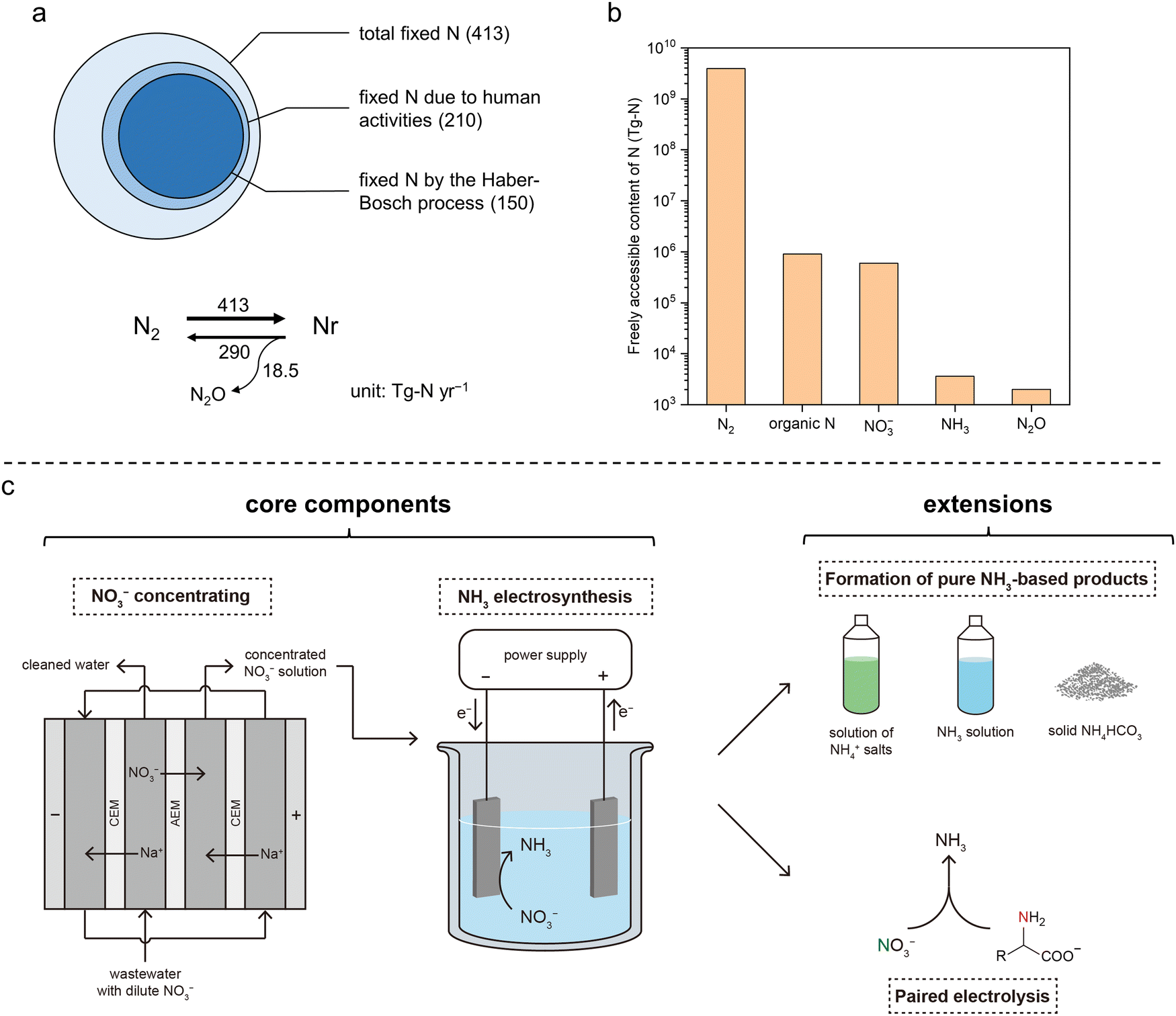 | ||
| Fig. 1 Global N balance, N accessibility, and the presented integrated sustainable process. (a) Simplified annual balance of the global N cycle. Top: Contribution of human activities to the fixation of N2. Bottom: Estimation of the rates of N2 fixation (N2 to Nr), denitrification (NO3− to N2), and N2O generation accompanied by denitrification. The numbers are in teragrams of N per year (Tg-N yr−1) and were obtained from Ref. 5. (b) Estimated amounts of freely accessible N element in different forms in the global ecosystem. Data are obtained from Ref. 2. Organic N, NO3−, NH3, and N2O are the four most abundant forms of accessible Nr. (c) Schematic of the integrated sustainable process for upcycling waste nitrogen in this work. The two core components are (1) NO3− recovery from low-concentration waste streams by electrodialysis and (2) NO3−-to-NH3 conversion by electrolysis. Two extensions were also demonstrated, including the formation of NH3-based chemicals and paired electrolysis. Abbreviations: CEM, cation-exchange membrane; AEM, anion-exchange membrane. | ||
Sustainable solutions to this human-induced problem have been actively pursued in recent years, such as the electrochemical reduction of NO3− (NO3RR). If NO3− in waste streams can be efficiently recovered and converted to NH3 (eqn (1)), this NH3-centric process will alleviate the environmental impacts of NO3−, while substantially decreasing NH3 demand from the Haber–Bosch process using fossil fuel-derived H2:12,13
| NO3− + 2H2O → NH3 + 2O2 + OH− | (1) |
Despite the successful development of some electrocatalysts for the NO3−-to-NH3 process in previous works (Table S1, ESI†),14–19 many of them involve noble metals and/or require complicated synthetic procedures, making them less economically attractive, especially considering the electricity consumption for this 8-electron-transfer reaction. Moreover, NO3− is highly distributed with only tens or hundreds of ppm NO3−–N in typical waste streams;12 thus, an efficient and sustainable concentrating step is another prerequisite for the high-performance NH3 electrosynthesis. Nevertheless, a systematic assessment of the technical and economic feasibility of NO3− concentration is critically missing in the current research field.
In this work, we report an integrated electricity-driven process for economically upcycling waste NO3−–N enabled by low-concentration NO3− electrodialysis and high-performance NH3 electrosynthesis from NO3− reduction (Fig. 1c). In a membrane-free alkaline electrolyzer (MFAEL) with a NaOH/KOH/H2O as the robust electrolyte, an NH3 partial current density of 4.22 ± 0.25 A cm−2 from NO3− reduction with a faradaic efficiency (FE) of 84.5 ± 4.9% was achieved on a simple commercial nickel foam as the cathode material. Meanwhile, low energy consumption was demonstrated to recover NO3− from low concentration (7.14 mM, or 100 ppm NO3−–N) by efficient electrodialysis for the first time. The economic competitiveness was quantitatively analyzed for the combined process of the NO3− recovery (by the low-concentration electrodialysis) and the NO3−-to-NH3 conversion (by the high-performance electrolysis), as compared to the prevailing treatment methods of waste nitrogen. As one extension of the integrated process, continuous production of pure NH3-based chemicals (NH3 solution and solid NH4HCO3) was realized without the need for additional separation procedures. As another logical extension, pairing NO3− reduction on the cathode with the oxidation of organic Nr compounds on the anode led to NH3 production from both electrodes simultaneously, realizing the convergent transformation of various Nr into NH3 as the sole N-containing product. The integrated process offers an all-sustainable and economically viable route for upcycling waste NO3−–N into the highest-demanded N-based chemical product – NH3, so that the growing trend of regional and seasonal Nr buildup could be largely decelerated and reversed.
Results and discussion
High-rate NH3 production by NO3RR in NaOH/KOH/H2O
With ultrahigh alkalinity, the “NaOH/KOH/H2O” electrolyte was first introduced in an attempt to convert N2 to NH3, but the system was later confirmed to completely reduce NOx−–N even at a trace amount of NH3 on simple metal electrodes.20–22 Such an unexpected finding implies that this strongly alkaline electrolyte holds potential for efficiently converting Nr into NH3 for the alternative upcycling of waste nitrogen.Thermodynamic analysis performed in this work (Fig. S2, ESI†) clearly indicates that the reduction of NO3− to NH3 is much more favorable than the reduction of water (i.e., the hydrogen evolution reaction, HER). Furthermore, the formation of gaseous NH3 is even more favorable than that of aqueous NH3 (NH3·H2O) at temperatures greater than 30 °C. In addition, if the produced NH3 can be removed timely from the reaction system (such as by a carrier gas flow), the thermodynamic cell voltage will be further reduced due to the shift in the chemical equilibrium.
Motivated by these results, we investigated the Nr-to-NH3 conversion in the NaOH/KOH/H2O electrolyte on simple nickel (mesh and foam) electrodes at a range of elevated temperature of 80–200 °C in a one-compartment MFAEL system (Fig. S3, ESI†). In the NaOH/KOH/H2O electrolyte with a carefully-chosen composition (containing equimolar NaOH and KOH with 40 wt% of water), the NO3−-to-NH3 conversion on simple Ni cathodes is surprisingly active: an NH3 partial current density of 4.22 ± 0.25 A cm−2 was obtained with 84.5 ± 4.9% of FE towards NH3 and 82.0 ± 0.2% of NO3− conversion on a commercial nickel foam at 80 °C (Fig. 2a and Fig. S4a, ESI†). Despite the slightly lower faradaic efficiency and the mildly elevated temperature, such a remarkable NH3 partial current density on the simple Ni foam is among the highest performances by far in the field (Fig. 2b and Table S1, ESI†), which is roughly double that on the Co-NAs14 (2.23 A cm−2 at room temperature) and quadruple that on the Ru-CuNWs15 (0.965 A cm−2 at room temperature). At lower current densities, the NO3− conversion can be improved to 94.5–96.5% at 100–500 mA cm−2, while maintaining a high level of FE for NH3 (84.0%–92.2%) (Fig. S4b, ESI†). Furthermore, the MFAEL system can function efficiently at temperatures up to 200 °C without considerable decrease in the FE towards NH3 or NO3− conversion (Fig. 2d and Fig. S5, ESI†). Notably, raising the initial NO3− concentration can further enhance the FE towards NH3 to 99.5% at 500 mA cm−2, while the NO3− conversion remained high (98.8%) (Fig. 2e).
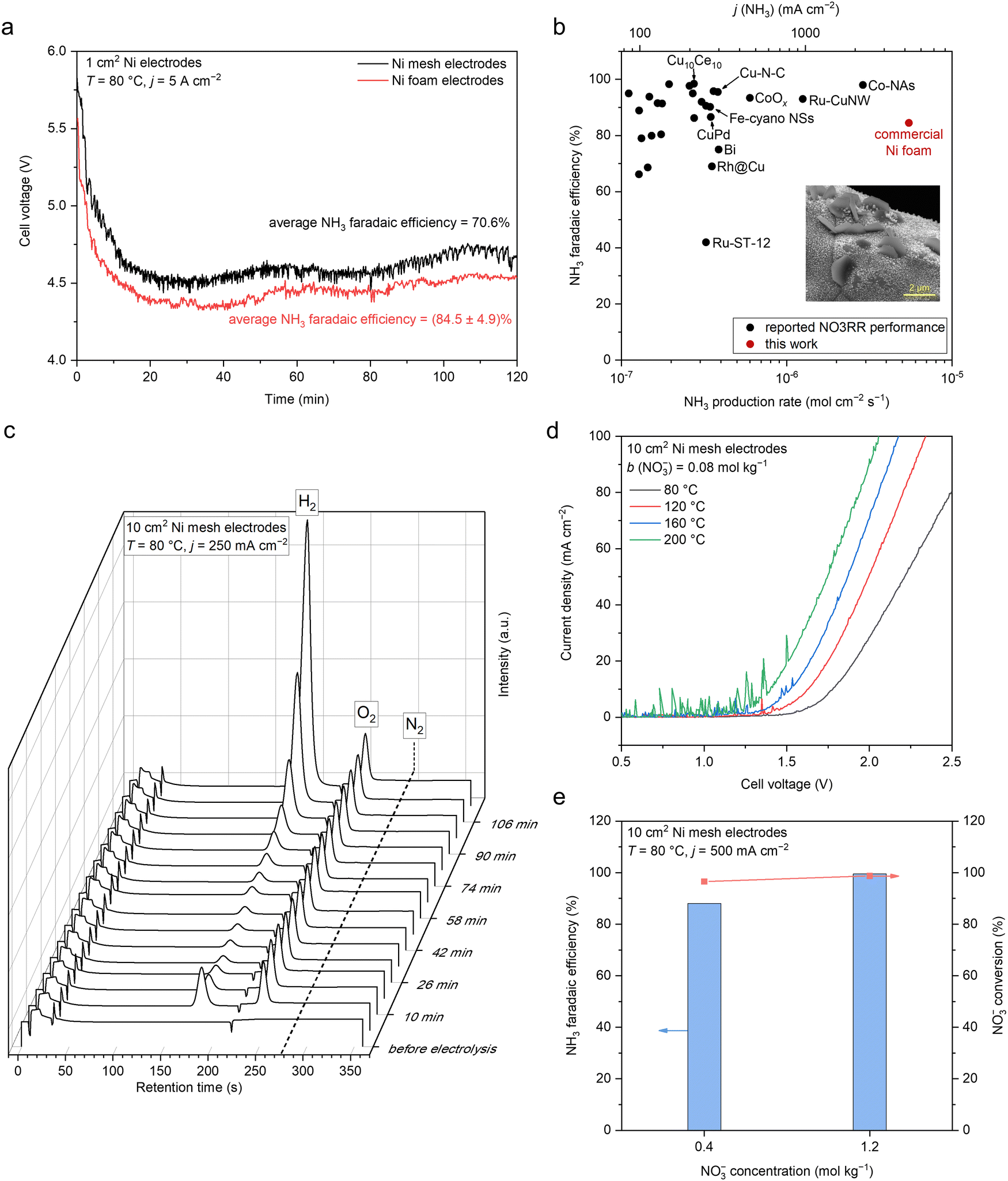 | ||
| Fig. 2 Electrochemical NH3 production by NO3RR in the NaOH/KOH/H2O electrolyte in MFAEL. (a) Cell voltage profiles of the 2-hour NO3RR test at 5 A cm−2 using two identical Ni mesh or Ni foam electrodes (1 cm2 geometric area). (b) Comparison of the NO3RR performance in this work with reported state-of-the-art performances. Data are summarized in Table S1 (ESI†). The inset shows the SEM image of the post-electrolysis Ni foam cathode. (c) Profile of online GC (with 99.999% Ar as the carrier gas) graphs during the 2-hour NO3RR test in MFAEL at 250 mA cm−2. The retention time was 187 s for H2, 248 s for O2, and 278 s for N2. Only a trace level of N2 (∼400 ppmv) was detected throughout the electrolysis, corresponding to <1% FE towards N2. Note that this value is close to the background concentration of N2, confirming that NO3RR in the NaOH/KOH/H2O electrolyte strongly favors the production of NH3, and the N–N coupling pathway is inhibited. (d) LSV curves in the NaOH/KOH/H2O electrolyte with 0.08 mol kg−1 of added KNO3 at different temperatures. The scan rate was 100 mV s−1. (e) Comparison of NO3RR performance with different initial NO3− concentrations in the electrolyte. Note that the applied charge was equal to the theoretical charge required for the full conversion of the added KNO3 into NH3; therefore at j = 500 mA cm−2, the electrolysis duration was 2 and 6 hours for the left and right columns, respectively. | ||
A series of control experiments performed in this study (Fig. S6, ESI†) confirms that the observed NH3 production is indeed from the electro-reduction of NO3−, without considerable interference from the contamination of other Nr (other than NO3−), non-faradaic reactions between the electrode and NO3−, or the reaction between NO3− and H2. The accuracy of NH3 quantification was cross-verified by comparing the results obtained from indophenol colorimetry (adopted method in this work) with 1H NMR and ion chromatography, and the difference in their results was <5% (Fig. S7, ESI†).
Online gas chromatography (GC) also confirmed that the HER is largely suppressed with a very low level of FE (e.g., an average FE of 5.35% at 250 mA cm−2), and N2 generation was not detected during the entire course of electrolysis (Fig. 2c and S8, ESI†). These results are in concert with the close-to-unity balance of N element (considering NO3−, NO2−, and NH3) for all measurements (Table S2, ESI†), showing that NH3 is the exclusive favorable product of NO3RR in the NaOH/KOH/H2O electrolyte. Note that the observed FE towards NO2− was lower than 6% for all measurements, indicating the facile sequential reduction of N–O bonds towards the fully hydrogenated product NH3.
Interestingly, replacing the carrier gas (high-purity N2) with air or high-purity O2 does not induce any considerable change in the cell performance (Fig. S9, ESI†), demonstrating the robustness of the MFAEL system, as inexpensive air can be used to realize efficient product separation without interference from the O2 content. Separating the catholyte and anolyte with a porous PTFE mesh resulted in a similarly high FE (86.7%, Fig. S10, ESI†), which strongly suggests that the co-generated H2 and O2 have minimal impact on the performance of the NO3RR.
High alkalinity of NaOH/KOH/H2O electrolyte is a critical prerequisite for the high-efficiency NO3−-to-NH3 conversion in MFAEL. 1![[thin space (1/6-em)]](https://www.rsc.org/images/entities/char_2009.gif) :1 molar NaOH/KOH was chosen to constitute the ternary NaOH/KOH/H2O electrolyte for this study due to the optimal performance and the maximum window for tuning water content, compared to the binary NaOH/H2O or KOH/H2O compositions (Fig. S11a, ESI†).23 Increasing the water content of the electrolyte from 40 wt% to 91 and 99 wt% (40, 91, and 99 wt% of water content corresponds to 15, 2, and 0.2 M of OH− concentration, respectively) leads to a significant decrease in the FE towards NH3 and the NO3− conversion (Fig. S11b, ESI†). In addition, higher alkalinity facilitates the evolution of produced NH3 from the MFAEL reactor, as observed from the distribution of NH3 after electrolysis (Fig. S11c, ESI†). These tendencies agree with the thermodynamic calculation results in Fig. S2 (ESI†). The type of chosen alkali for the electrolyte has modest effect on the NO3RR performance at high alkalinity (15 M OH−, Fig. S11a, ESI†); with 2 M OH−, an apparent cationic effect was observed, and FE towards NH3 shows the discernable trend of Li+ < Na+ < K+ (Fig. S11d, ESI†).
:1 molar NaOH/KOH was chosen to constitute the ternary NaOH/KOH/H2O electrolyte for this study due to the optimal performance and the maximum window for tuning water content, compared to the binary NaOH/H2O or KOH/H2O compositions (Fig. S11a, ESI†).23 Increasing the water content of the electrolyte from 40 wt% to 91 and 99 wt% (40, 91, and 99 wt% of water content corresponds to 15, 2, and 0.2 M of OH− concentration, respectively) leads to a significant decrease in the FE towards NH3 and the NO3− conversion (Fig. S11b, ESI†). In addition, higher alkalinity facilitates the evolution of produced NH3 from the MFAEL reactor, as observed from the distribution of NH3 after electrolysis (Fig. S11c, ESI†). These tendencies agree with the thermodynamic calculation results in Fig. S2 (ESI†). The type of chosen alkali for the electrolyte has modest effect on the NO3RR performance at high alkalinity (15 M OH−, Fig. S11a, ESI†); with 2 M OH−, an apparent cationic effect was observed, and FE towards NH3 shows the discernable trend of Li+ < Na+ < K+ (Fig. S11d, ESI†).
Notably, the re-deposition of partially oxidized nickel species on the cathode was observed during electrolysis, which extends the electrochemical surface area contributing to the high-performance NO3−-to-NH3 conversion. No substantial change was found on the anode in the post-electrolysis characterization by scanning electron microscopy (SEM), while the formation of nanoparticles of ∼100 nm and larger hexagonal flakes of 1–2.5 μm were found on the cathode (Fig. 2b and Fig. S12, ESI†), in accordance with the observed darkening of the cathode subject to electrolysis (Fig. S13, ESI†).
The energy-dispersive X-ray spectroscopy (EDS) analysis reveals the Ni/O atomic ratio of 3.66 and 0.72 on the nanoparticles, respectively; and an overall increase in oxygen content from 1.2 at% before electrolysis to 24.3 at% afterwards (Fig. S14–S16, ESI†). The surface of the post-electrolysis cathode consists of a layer of Ni(OH)2, as suggested by XPS and Raman spectra (Fig. S17, ESI†). These deposits increased the roughness factor (RF) of the Ni cathode by 1.11 and 1.69 times for Ni mesh and Ni foam, respectively (Fig. S18, ESI†), which should be a contributor to the enhancement of the NO3RR activity.
The formation of those cathodic deposits should come from the migration of Ni from the anode to the cathode during electrolysis (namely, re-deposition): anodic Ni is initially oxidized to Ni(OH)2/NiOOH which is an active catalyst for the oxygen evolution reaction (OER),24 followed by its partial dissolution in a strongly alkaline electrolyte in the forms of Ni(OH)3− or Ni(OH)42−;25 subsequently, these soluble Ni(II) species are re-deposited onto the cathode. When a Cu mesh was used as the cathode while keeping the Ni mesh as the anode, similar deposits were observed (Fig. S19 and S20, ESI†); however, when a graphite rod was used as the anode while using Ni foam as the cathode, no deposit was observed after electrolysis (Fig. S21, ESI†). Clearly, the two experiments verified that the origin of those deposits is the Ni anode. As such, the re-deposition of Ni-species in this work should be distinguished from the “cathodic corrosion” reported by Koper et al.26 Also, the re-deposition process is possibly associated with the higher cell voltage and lower FE towards NH3 at the initial period of electrolysis (as shown in Fig. 2a and c).
It should be noted that such a re-deposition occurs only within the near-surface region of the electrodes while the bulk composition of the electrodes remains largely unchanged, as evidenced by the X-ray diffraction (XRD) (Fig. S17a, ESI†). This is also consistent with the very minor change in mass of the Ni electrodes (<1 mg) operated at 5 A for 2 hours. In real applications, the longevity of both Ni electrodes can be maintained by periodically reversing the current flow.
Production of pure NH3-based chemicals from a scale-up MFAEL
Thanks to the high activity and operational robustness of the MFAEL, we increased the reaction capacity from 100 mL to 2.5 L under industrial-level current density (Fig. S23, ESI†). Two 100 cm2 Ni mesh electrodes were folded and immersed in the electrolyte, and a constant current of 25 A was applied (i.e., 250 mA cm−2). With the scaled-up system, NO3RR was carried out for 24 hours, resulting in an average FE of 70.4% towards NH3 and a steady-state cell voltage of 2.7 V (Fig. 3a). As a result, a very high NH3 production rate of 82.1 mmol h−1 was achieved in this scaled-up MFAEL reactor.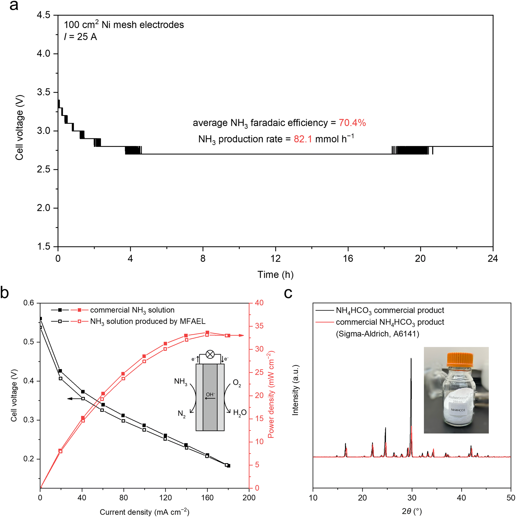 | ||
| Fig. 3 Producing pure NH3-based chemicals in a scaled-up MFAEL system. (a) Cell voltage profile for the scaled-up MFAEL system in a 24-hour NO3RR test at 25 A. Note that the steps in the voltage profile are due to the minimum resolution of our DC power supply (0.1 V) at the large current rating (30 A). (b) Polarization and power density curves for the fuel cells with MFAEL-derived NH3 solution and commercial NH3 solution (with the same concentration) as the anode fuel. The fuel cell was operated at 80 °C, and 1.25 M KOH was added to the NH3 solutions. (c) XRD patterns of the MFAEL-derived NH4HCO3 solid and a commercial NH4HCO3 product. The inset photo shows the collected NH4HCO3 product (74.2 g) from 24 hour electrolysis in a scaled-up MFAEL. | ||
The produced NH3 from the MFAEL can be managed in different forms: NH4+ salts (such as sulfate), aqueous NH3 solutions, and a solid NH4HCO3 product (Fig. 1c). When an acidic absorbing solution (e.g., H2SO4 solution) is used as for most measurements in this work, NH4+ salts are the final products in solution. The collection efficiency is almost 100% under varying conditions, as evidenced by the close-to-unity N balance for all tests (Table S2, ESI†).
Alternatively, when water (5 °C) is used for NH3 absorption, despite a slightly lower collection efficiency (95.6%) (Fig. S23a, ESI†), a highly-concentrated NH3 solution (4.13 M, or around 7 wt%) was obtained after the 24 hour electrolysis from the scaled-up MFAEL. The MFAEL-derived NH3 solution (with added 1.25 M KOH) was directly supplied as the anode fuel for an anion-exchange membrane fuel cell (Fig. 3b and Fig. S24, ESI†), outputting a peak power density of 33.7 mW cm−2 at 80 °C, which is a reasonable performance among the reported values of direct NH3 fuel cells using commercial catalysts, membranes, and ionomers.27 Notably, the I–V curve and power density profile show no significant difference between the fuel cells fed with MFAEL-derived NH3 solution and that fed with a commercial NH3 solution of the same concentration, suggesting the high purity of the MFAEL-derived NH3 solution.
In another case, the NH3-containing outlet gas from MFAEL was absorbed by a CO2-bubbling water solution at 5 °C. Owing to the acidity of CO2, NH3 collection efficiency as high as 99.9% was achieved (Fig. S23a, ESI†). Co-absorbing NH3 and CO2 in water produces NH4HCO3 with the simultaneous collection of NH3 and the capture of waste CO2. Due to the limited solubility of NH4HCO3 (around 14.3 g in 100 mL water at 5 °C), its precipitation is well controlled by altering the volume and temperature of the absorbing solution: after 24 hour electrolysis in the scaled-up MFAEL, the precipitate in the absorbing solution (5 °C) was collected by vacuum filtration, ethanol washing, and drying under ambient conditions. 74.2 g of solid NH4HCO3 product was obtained and its high purity was confirmed by XRD (Fig. 3c and Fig. S23, ESI†). One further use of such NH4HCO3 involves a bicarbonate electrolyzer with a bipolar membrane, in which CO2 is generated in situ and reduced to formate, CO, or other value-added products.28,29
Electrodialysis for energy-efficient concentration of NO3−
NO3− is one of the most abundant and widespread forms of Nr in nature, and therefore recovering NO3− from dilute waste streams (on levels of tens or hundreds of ppm NO3−–N12) and concentrating it into sufficient concentrations (such as 1 or 2 M) is an indispensable step of the NO3− treatment by high-rate NH3-producing electrolysis. Compared with reverse osmosis (RO), ion exchange (IX), and other NO3−-recovering technologies, electrodialysis (ED) is particularly suitable for low- to medium-concentration NO3− feedstocks, because of its lower energy consumption (cf. RO) and much smaller chemical consumption (cf. IX). For typical industrial ED systems, a few hundred electrodialysis pairs are assembled between one set of electrodialysis electrodes, and a single electrodialysis pair is often constructed by the configuration of “CEM | diluate |AEM| concentrate”, where CEM and AEM stand for cation-exchange membrane and anion-exchange membrane, respectively; and diluate and concentrate stand for the NO3−-giving feedstock solution and the NO3−-receiving product solution, respectively. As such, the “pair voltage” arising from a single electrodialysis pair largely controls the energy consumption of ED, in addition to the pumping-caused energy consumption.We have experimentally verified that the low pair voltage for concentrating NO3− by ED is achievable and predictable with a small intermembrane distance of 0.5 mm and a sufficient fluid velocity of 10 cm s−1 (Fig. S25, ESI†). Fig. 4 shows the pair voltage profile of our ED experiment of concentrating 7.14 mM (100 ppm NO3−–N) into 2 M NO3− (28000 ppm NO3−–N) with 75% of the designed NO3− recovery at an appropriate ED current density of 1 mA cm−2. The observed initial and final pair voltage was 0.39 and 0.63 V, respectively, both of which are highly consistent with the theoretical predictions (0.376 and 0.671 V, respectively) by considering both the Donnan potential rise (from both cation and anion) and the ohmic potential rise (from two membranes and two solutions). The observed coulombic efficiency of NO3− concentration was 96%. A consistent pair voltage profile with the predicted one was also observed at 2 mA cm−2 (Fig. S26, ESI†). Our experimental verification on low pair voltage and high coulombic efficiency is the first result in the NO3− concentrating with low concentrations by electrodialysis to our best knowledge. Considering the NO3− concentration in the real-world waste streams, the NO3− recovery is deemed feasible.
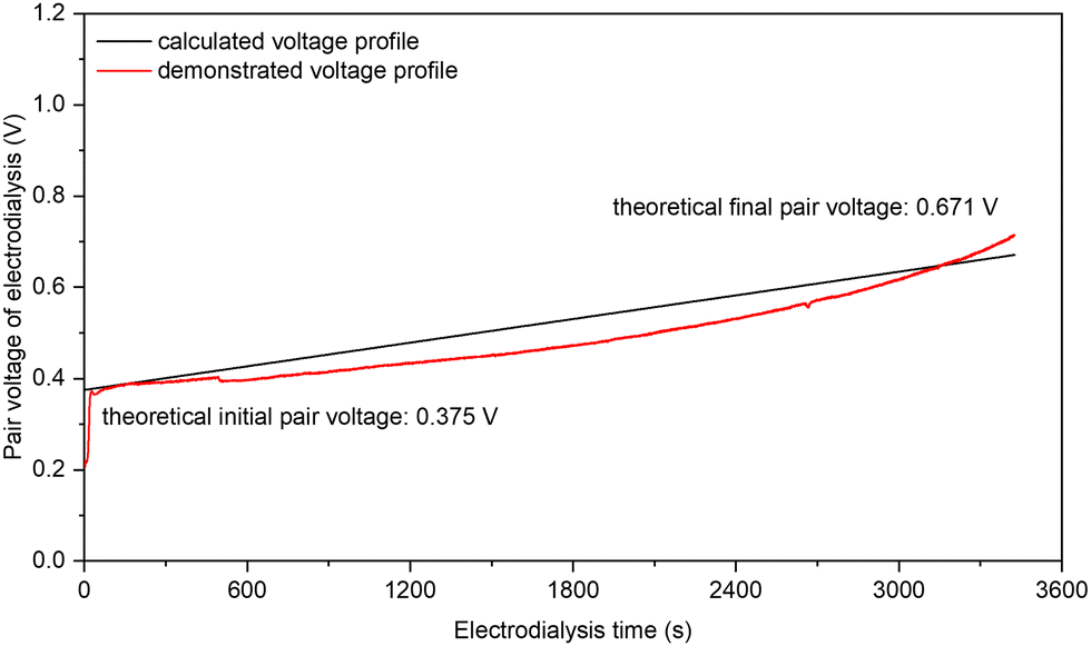 | ||
| Fig. 4 The voltage profiles of one electrodialysis pair along with electrodialysis time for NO3− concentration. A single electrodialysis pair is constructed by the configuration of “CEM | diluate |AEM| concentrate” in which the CEM and the AEM are FKA-PK-130 and FAA-PK-130, respectively, both from Fuma-Tech; and the diluate and the concentrate are 7.14 mM KNO3 (100 ppm NO3−–N) and 2 M KNO3 (28000 ppm NO3−-N), respectively. The key experimental conditions include: 5 cm2 as the effective pair area, 1 mA cm−2 as the electrodialysis current density, 10 cm s−1 as the nominal fluid velocity for all channels (60 mL min−1), 0.5 mm as the distance between CEM and AEM in the electrodialysis pair, and 75% as the designed NO3− removal (3444 seconds). Note that the applied current density for ED is subject to the threshold set by the “limiting current density” calculated by the Rosenberg and Tirrell equation,41 and the obtained limiting current density is 4.62 and 1.19 mA cm−2 at the initial (7.14 mM) and the final diluate concentration (1.79 mM), respectively, under our experimental conditions. | ||
Techno-economic analysis of upcycling NO3−–N from dilute waste streams
To better understand the economic viability of concentrating NO3− by ED and its subsequent conversion to NH3 in MFAEL, a model of techno-economic analysis (TEA) was established in this study.000 ppm NO3−–N) of the concentrate concentration, 80% of NO3− recovery, 4 cm s−1 of nominal fluid velocity, 0.5 mm of pair distance, and $0.07 kW h−1 of electricity price, the obtained LTC is merely $5.75 per kmol-NO3−.
Fig. 5a presents a contour map of LTC with respect to the diluate concentration and NO3− recovery, both of which are related to the workload and requirement of NO3− feedstock. Clearly, the LTC sharply decreases with increasing diluate concentration and mildly increases with raising NO3− recovery. The concentration of initial diluate is the most influential parameter, and its impacts on OPEX and LCC are presented in Fig. 5b. The LTC is dominated by OPEX and LCC for the initial diluate concentration ranges of <100 and >300 ppm NO3−–N, respectively. This trend is essentially driven by the exponentially-growing energy consumption from both ED operation and fluid pumping when lowering the NO3− concentration in the diluate solution. By contrast, the impact of electricity price is simply linear to OPEX (Fig. S29, ESI†).
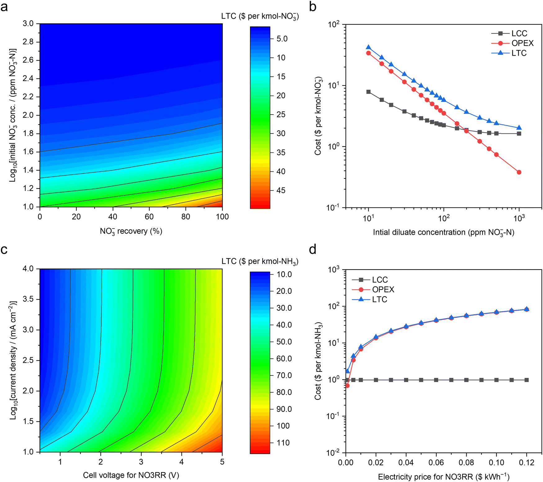 | ||
| Fig. 5 Techno-economic analysis of upcycling NO3−–N from dilute waste streams. (a) The contour map for the LTC of NO3− concentration by electrodialysis with respect to the initial NO3− concentration in the diluate and the designed NO3− recovery from the diluate ($0.07 kW h−1 of electricity cost). (b) LTC, OPEX, and LCC along with the initial diluate concentration ($0.07 kW h−1 of electricity price and 80% of designed NO3− recovery). Based on a typical medium-size commercial electrodialysis system (40 cm × 160 cm for each electrodialysis pair, and 250 electrodialysis pairs in total), the LCC was calculated via the standard capital recovery method, assuming 40 years of service time,42 19% as the cost ratio of maintenance to the system, 3% of annual discount rate,31 83.3% of capacity factor, and 90% of coulombic efficiency. (c) The contour map for the LTC of NH3 production by NO3RR in MFAEL with respect to the electrolytic current density and cell voltage ($0.07 kW h−1 of electricity price). (d) The impact of electricity price on the LTC and OPEX of the NO3RR (2.7 V of cell voltage and 250 mA cm−2 of current density). Capital cost analysis was performed based on a customized medium-size MFAEL reactor with 100 L electrolyte capacity with the total electrode area of 3.36 m2. The cost of all identified materials and ancillary/auxiliary parts/components was estimated to be $1164 per system. Considering all unidentified parts (10%) and all other associated costs,30 the total capital cost of this electrolyzer system was projected to be $3121 per system. Other assumptions and methodologies are discussed in the ESI†. | ||
The OPEX of NO3RR was solely calculated from energy consumption at a certain electricity price. In addition to the electrolysis (cell voltage and current), the energy consumptions from both mixing and heating are considered.
Fig. S32 (ESI†) shows the strong relationship between the energy consumption and the cell voltage of NO3RR, largely because the mixing consumes significantly less energy than the electrolysis (e.g., 0.17 vs. 45.03 kW h per kmol-NH3 under 2.7 V of cell voltage at 250 mA cm−2). The contour map for the LTC of NO3RR in $ per kmol-NH3 with respect to the electrolytic current density and cell voltage was presented in Fig. 5c, assuming $0.97 kmol-NH3 as the LCC and $0.07 kW h−1 as the electricity price. Consistent with Fig. S32 (ESI†), cell voltage is a dominant parameter controlling the LTC for NO3RR. Increasing the current density leads to a decrease in the LTC (Fig. S33, ESI†), but its impact is most pronounced below 50 mA cm−2; at higher current densities, the LTC is overwhelmingly dominated by the OPEX, suggesting that future improvement should be primarily focused on lowering of the cell voltage of the MFAEL. It should be pointed out that the observed trend with respect to current density is greatly attributed to the very low level of LCC, thanks to the inexpensive and durable materials used in the system (such as nickel and stainless steel). When expensive or non-durable catalytic materials are used, the LTC could be comparable to the OPEX. Owing to the major contribution of the energy cost to the LTC, future decrease in the electricity price will also be greatly beneficial to lowering the LTC (Fig. 5d). Though higher current density does not substantially lower the LTC of the MFAEL system, it does offer a level of system flexibility of operating at a reduced capacity factor to benefit from the lower-priced or even free electricity from excessive renewable generation. The advantage of utilizing cheap/free electricity may significantly reduce the LTC, in light of the heavy energy consumption.
On the assumptions above, the LTC of NO3RR in MFAEL under our typical operating conditions (2.7 V and 250 mA cm−2) turns out to be $48.42 per kmol-NH3. Note that the OPEX related to heating is merely $2.25 per kmol-NH3 (Fig. S31, ESI†), which is only 4.6% of the LTC of NO3RR. Considering the low LTC for concentrating NO3− ($5.75 per kmol-NO3−) by ED, our newly-proposed upcycling strategy not only offers a lower cost (i.e., $54.57) compared to the current cost of N removal in wastewater treatment plants (around $65 per kmol-N32), but also leaves a competitive profit margin with the market price of NH3 ($9.35 per kmol).
A convergent Nr-to-NH3 process enabled by MFAEL
Thus far, the OER has been the anodic reaction in the investigated systems, which does not produce value-added products itself. Alternatively, a paired electrolysis system can be constructed by combining the reduction of NO3− (on cathode) and oxidation of C–N bonds in organic Nr compounds (on anode) in one electrolytic cell (Fig. 6a). Organic Nr compounds (such as amino acids and proteins) represent a large portion of the global inventory of Nr (Fig. 1b), but their chemical conversion remains challenging owing to the high stability of C–N bonds.33 In such a paired system, organic Nr serves as an additional source of N for NH3 production and provides electrons for NO3− reduction. Meanwhile, the anode product is switched from low-value O2 (through OER) to value-added oxidized organic compounds such as carboxylic acids with the simultaneous release of NH3, increasing economic feasibility.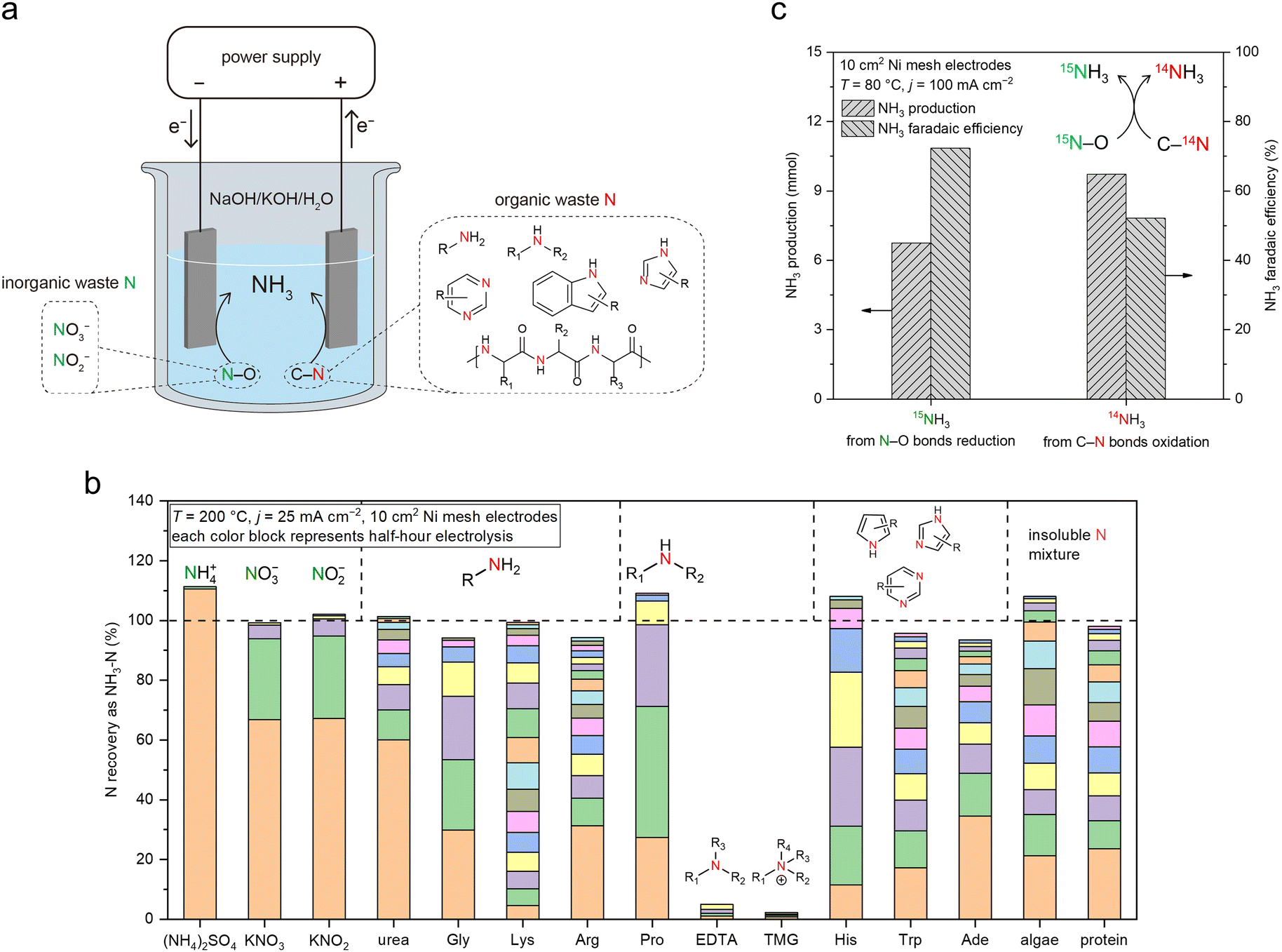 | ||
| Fig. 6 A convergent Nr-to-NH3 process enabled by MFAEL. (a) Illustration of the proposed concept, in which the waste materials containing N–O bonds (inorganic wastes) and C–N bonds (organic wastes) are simultaneously converted to NH3 in MFAEL as the sole N-containing product. (b) Screening test results for different forms of Nr. Electrolysis was carried out at 25 mA cm−2 and 200 °C with 0.2 mmol of added N for each chemical, and NH3 was collected every half hour until no significant increase in its production was detected. The y-axis (NH3–N recovery) corresponds to the ratio of the produced NH3–N to the initially added Nr–N. Each color block represents the NH3 production from a half-hour period. The representative chemical structures of the Nr compounds are labeled on the top of the columns. Detailed reactant abbreviations, structures, and test results are summarized in Table S3 (ESI†). (c) Production of and FE towards 14NH3 and 15NH3 during the paired electrolysis in MFAEL containing both 15N–O and C–14N bonds. K15NO3 (9.3 mmol) and alanine (18.7 mmol) were chosen as the model chemicals containing 15N–O and C–14N bonds, respectively. The produced 14NH3 and 15NH3 were quantified by 1H NMR. | ||
To examine the NH3 formation from organic Nr in NaOH/KOH/H2O, we first screened a series of N-containing compounds with representative chemical environments of N element (12 organic Nr compounds and 3 inorganic Nr compounds) at 200 °C with an applied current density of 25 mA cm−2 (Fig. 6b and Table S3, ESI†). Note that most organic Nr compounds we examined in this work are amino acids (listed in Table S3, ESI†), which are common and major forms of organic N in the ecosystems.34 Interestingly, except for EDTA (ethylenediaminetetraacetic acid) and TMG (trimethyl glycine), N from all other N-containing compounds (10 in organic Nr and 3 in inorganic Nr) examined in this work was completely converted to NH3 in its final form within a few hours of electrolysis. Compared to inorganic Nr (with N–O bonds), organic Nr compounds require longer reaction time for full conversion, because of the higher stability of C–N bonds.35 N atoms connected with longer carbon chains, conjugated structures, or more than two adjacent C atoms appear to be less reactive, though in most cases they can ultimately be converted to NH3. The high Nr conversion and high NH3 selectivity enable a convergent pathway from various forms of Nr towards NH3 as the sole N-containing product.
We then investigated the products after the cleavage of C–N bonds in NaOH/KOH/H2O (Fig. S34, ESI†). Glycine and alanine were chosen as the reactants due to their structural simplicity, and electrolysis was performed at 80 °C. To track the carbon-containing products, 13C-labeled chemicals were used as the reactants, and the products were analyzed by 13C nuclear magnetic resonance (NMR) spectroscopy. The results show that the oxidations of both organic Nr compounds are 4-electron-transfer processes, in which the C–N bond scission is accompanied by the oxidation of the C element and the release of NH3. Upon the cleavage of the C–N bond, the identified product for glycine oxidation was oxalate; while for alanine, a subsequent decarboxylation occurs, giving rise to acetate and carbonate (eqn (2) and (3) below):
| H2N–CH2–COO− (glycine) + 5OH− → C2O42− + NH3 + 3H2O + 4e− | (2) |
| H2N–CH(CH3)–COO− (alanine) + 6OH− → CH3COO− + CO32− + NH3 + 3H2O + 4e− | (3) |
Similar results should be expected for Nr in more complex structures, demonstrating that MFAEL is capable of converting organic N-containing wastes into value-added carboxylic acid products, while largely retaining the skeleton of the original molecules. Additional experimental results (detailed in Fig. S35 and S36, ESI†) confirmed that both applied electricity and high alkalinity are indispensable conditions for the reaction to proceed efficiently in MFAEL. In the presence of organic Nr, production of O2 from OER is apparently suppressed as confirmed by online GC (Fig. S37, ESI†). Interestingly, none of the volatile carbon-containing products (CO, CH4, CO2, C2H2, C2H4, and C2H6) was detected by online GC during the conversion of organic Nr (Fig. S38, ESI†), indicating that carbon is retained in the electrolyte.
Knowing that NH3 can be produced via the oxidation-assisted cleavage of C–N bonds, we paired the reduction of N–O bonds with the oxidation of C–N bonds, aiming to generate NH3 from both sources (Fig. 6c and Fig. S39, ESI†). For this purpose, KNO3 and alanine were added into MFAEL as model reactants containing N–O and C–N bonds:
| 2H2N–CH(R)–COO− + NO3− + 3OH− → 2R–COO− + 2CO32− + 3NH3 | (4) |
Notably, to determine the respective contribution of NH3 production from each source, the N–O reactant was isotopically labeled using K15NO3, and the NH3 product was analyzed by 1H NMR to differentiate 14NH3 and 15NH3. With this configuration operated at 100 mA cm−2, 1H NMR suggests that the produced NH3 is derived from both N–O reduction and C–N oxidation with their corresponding FE of 72.3% and 52.1%, respectively (Fig. 6c). Based on the quantification of reactants and products, the elemental balance of nitrogen and carbon was 87.8% and 80.0%, respectively (detailed in Fig. S40, ESI†), suggesting that eqn (4) is a reasonable description of the paired process. Considering the abundance of organic Nr in the wastes from certain industries such as meat processing facilities,36,37 this “one-pot” strategy for converting various Nr into NH3 not only improves the utilization of electrons, but also mitigates the cost of reactant separation and purification for complex real waste matrices.
Conclusions
In this work, an integrated sustainable process was presented for economically upcycling waste nitrogen. In particular, a versatile, robust, and inexpensive MFAEL system was developed to convert various forms of waste Nr into NH3 convergently. Taking advantage of its strong tendency towards hydrogenating N–O bonds, a partial current density as high as 4.22 ± 0.25 A cm−2 for NH3 production was achieved by NO3− reduction without generating considerable N–N coupling products.Upscaling the MFAEL system is straightforward due to its structural simplicity and the inexpensiveness of its components. The 2.5 L scaled-up reactor is capable of producing NH3 at 25 A with an average FE of 70.4% from NO3RR. By properly choosing the NH3 absorbing conditions, different forms of pure NH3-based chemicals (NH4+ salts, NH3 solution, and solid NH4HCO3) can be continuously produced from the conversion of waste Nr in MFAEL. Since the NH3 product from MFAEL is in a gas mixture, pure NH3 gas may also be obtained through established economical gas separation technologies (such as pressure swing adsorption) without the need for additional distillation steps.38 Use of organic or inorganic additives could increase the co-absorption efficiency of MFAEL-derived NH3 and waste CO2,39 making it a promising dual-purpose process that fixes waste N and C into one useful chemical product NH4HCO3. Meanwhile, scale-up issues such as electrolyte mixing and heat management need to be addressed to ensure efficient mass transport and stable operation. In fact, the resemblance of MFAEL configuration to the alkaline water electrolyzers (typically operated at 70–90 °C with 25–35 wt% of KOH solutions40) has suggested a clear potential towards commercialization, since the latter has been commercially available for over 50 years.
The feasibility of concentrating NO3− by a low-energy cost electrodialysis process was validated both experimentally and analytically via a comprehensive TEA study. Combining NO3− concentration by electrodialysis and its reduction in MFAEL generates a competitive levelized total cost of the waste-derived NH3 product, largely owing to the remarkably low material cost of the MFAEL system. As illustrated by the TEA results, the reduction of the cell voltage of NO3RR should be the primary focus of future work.
In the present work, Ni was chosen as the electrode material primarily due to its inexpensiveness and its excellent corrosion resistance. Not limited to Ni, other metals such as Co, Ru, and Cu can also serve as the cathode in the KOH/NaOH/H2O electrolyte, and their performance comparison under the same test conditions is shown in Fig. S41 (ESI†). The development of inexpensive, stable, and more active electrocatalysts should be a synchronous task of reactor optimization.
In the NaOH/KOH/H2O electrolyte, C–N bonds in organic Nr compounds can be oxidized to produce NH3. By controlling the operating conditions of MFAEL, ∼100% recovery of the most common forms of Nr into NH3 can be realized, making it a sensitive and accurate tool for determining N content in complex real-world samples. Oxidation of C–N bonds results in the production of carboxylic acids as a potentially value-added by-product, and pairing the oxidation of C–N bonds (on anode) with the reduction of N–O bonds (on cathode) in MFAEL leads to a cathodic and anodic FE of 72.3% and 52.1% for NH3 production at 100 mA cm−2, respectively, demonstrating its capability of extracting N element from real waste containing both oxidative and reductive forms of Nr. Notwithstanding the great potential of such a paired process, the quantitative impact of other impurities from real-world feedstocks is subject to further study. In addition, the trade-off between the economic benefits of carboxylic acid products and their separation costs needs to be optimized in future research.
Author contributions
W. Li and S. Gu proposed and supervised the research. Y. Chen set up the MFAEL system and performed most of the electrochemical measurements. P. Ammari-Azar carried out electrodialysis experiments. H. Liu carried out the product analysis by HPLC and performed the electrochemical characterization. J. Lee performed SEM and EDS characterization. Y. Xi assisted with the electrochemical measurements. S. Gu performed the techno-economic analysis. M. J. Castellano provided important and constructive suggestions for this work. Y. Chen, S. Gu, and W. Li wrote the manuscript.Conflicts of interest
There are no conflicts to declare.Acknowledgements
This research was supported by the U.S. National Science Foundation through the Future Manufacturing program (under grant no. CHE-2036944) and the ECO-CBET program (under grants no. 2219162 and 2219172), and by the Regents Innovation Fund of Iowa State Economic Development & Industry Relations. We are grateful to Dr Dapeng Jing for XPS measurements, Jacob F. Wheaton for Raman spectra collection, and Tianlei Li for assistance in NMR measurements. We thank Dr Zhiyou Wen (Gross-Wen Technologies, Inc.) and Hong Chen for kindly providing the algae powder samples. We also acknowledge fruitful discussions with Peter Hong, Dr Terry A. Houser, Dr Rodrigo Tarté, Dr Joseph G. Sebranek, and Dr Mark M. Wright from Iowa State University on the use of MFAEL for real N-containing wastes. S. Gu acknowledges the John A. See Innovation Foundation. W. Li acknowledges his Herbert L. Stiles Faculty Fellowship and the Presidential Interdisciplinary Research Initiative (PIRI) grant from Iowa State University.References
- N. Lehnert, H. T. Dong, J. B. Harland, A. P. Hunt and C. J. White, Nat. Rev. Chem., 2018, 2, 278–289 CAS.
- M. M. M. Kuypers, H. K. Marchant and B. Kartal, Nat. Rev. Microbiol., 2018, 16, 263–276 CAS.
- A. Uwizeye, I. J. M. de Boer, C. I. Opio, R. P. O. Schulte, A. Falcucci, G. Tempio, F. Teillard, F. Casu, M. Rulli, J. N. Galloway, A. Leip, J. W. Erisman, T. P. Robinson, H. Steinfeld and P. J. Gerber, Nat. Food, 2020, 1, 437–446 CAS.
- J. N. Galloway and E. B. Cowling, Ambio, 2021, 50, 745–749 Search PubMed.
- D. Fowler, M. Coyle, U. Skiba, M. A. Sutton, J. N. Cape, S. Reis, L. J. Sheppard, A. Jenkins, B. Grizzetti, J. N. Galloway, P. Vitousek, A. Leach, A. F. Bouwman, K. Butterbach-Bahl, F. Dentener, D. Stevenson, M. Amann and M. Voss, Philos. Trans. R. Soc., B, 2013, 368, 20130164 Search PubMed.
- J. N. Galloway, A. R. Townsend, J. W. Erisman, M. Bekunda, Z. Cai, J. R. Freney, L. A. Martinelli, S. P. Seitzinger and M. A. Sutton, Science, 2008, 320, 889–892 CAS.
- J. N. Galloway, J. D. Aber, J. W. Erisman, S. P. Seitzinger, R. W. Howarth, E. B. Cowling and B. J. Cosby, BioScience, 2003, 53, 341–356 Search PubMed.
- M. H. Ward, T. M. DeKok, P. Levallois, J. Brender, G. Gulis, B. T. Nolan and J. VanDerslice, Environ. Health Perspect., 2005, 113, 1607–1614 CAS.
- A. Temkin, S. Evans, T. Manidis, C. Campbell and O. V. Naidenko, Environ. Res., 2019, 176, 108442 CAS.
- M. H. Ward, R. R. Jones, J. D. Brender, T. M. de Kok, P. J. Weyer, B. T. Nolan, C. M. Villanueva and S. G. van Breda, Int. J. Environ. Res. Public Health, 2018, 15, 1557 Search PubMed.
- Grand Challenges - Introduction to the Grand Challenges for Engineering, https://www.engineeringchallenges.org/challenges/16091.aspx, (accessed November 13, 2021).
- P. H. van Langevelde, I. Katsounaros and M. T. M. Koper, Joule, 2021, 5, 290–294 Search PubMed.
- J. M. McEnaney, S. J. Blair, A. C. Nielander, J. A. Schwalbe, D. M. Koshy, M. Cargnello and T. F. Jaramillo, ACS Sustainable Chem. Eng., 2020, 8, 2672–2681 CAS.
- X. Deng, Y. Yang, L. Wang, X.-Z. Fu, J.-L. Luo, X. Deng, L. Wang, Z. X. Fu, J.-L. Luo and Y. Yang, Adv. Sci., 2021, 8, 2004523 CAS.
- F.-Y. Chen, Z.-Y. Wu, S. Gupta, D. J. Rivera, S. V. Lambeets, S. Pecaut, J. Y. T. Kim, P. Zhu, Y. Z. Finfrock, D. M. Meira, G. King, G. Gao, W. Xu, D. A. Cullen, H. Zhou, Y. Han, D. E. Perea, C. L. Muhich and H. Wang, Nat. Nanotechnol., 2022, 17, 759–767 CAS.
- Q. Hu, Y. Qin, X. Wang, Z. Wang, X. Huang, H. Zheng, K. Gao, H. Yang, P. Zhang, M. Shao and C. He, Energy Environ. Sci., 2021, 14, 4989–4997 CAS.
- Q. Gao, H. S. Pillai, Y. Huang, S. Liu, Q. Mu, X. Han, Z. Yan, H. Zhou, Q. He, H. Xin and H. Zhu, Nat. Commun., 2022, 13, 2338 CAS.
- J. Li, G. Zhan, J. Yang, F. Quan, C. Mao, Y. Liu, B. Wang, F. Lei, L. Li, A. W. M. Chan, L. Xu, Y. Shi, Y. Du, W. Hao, P. K. Wong, J. Wang, S. X. Dou, L. Zhang and J. C. Yu, J. Am. Chem. Soc., 2020, 142, 7036–7046 CAS.
- H. Liu, X. Lang, C. Zhu, J. Timoshenko, M. Rüscher, L. Bai, N. Guijarro, H. Yin, Y. Peng, J. Li, Z. Liu, W. Wang, B. R. Cuenya and J. Luo, Angew. Chem., Int. Ed., 2022, 61, e202202556 CAS.
- S. Licht, B. Cui, B. Wang, F. F. Li, J. Lau and S. Liu, Science, 2014, 345, 637–640 CAS.
- S. Licht, B. Cui, B. Wang, F.-F. Li, J. Lau and S. Liu, Science, 2020, 369, 780 CAS.
- Y. Chen, H. Liu, N. Ha, S. Licht, S. Gu and W. Li, Nat. Catal., 2020, 3, 1055–1061 CAS.
- G. J. Janz, C. B. Allen, N. P. Bansal, R. M. Murphy and R. P. T. Tomkins, Physical Properties Data Compilations Relevant to Energy Storage. II. Molten Salts: Data on Single and Multi-Component Salt Systems, U.S. Government Printing Office, Washington, 1979.
- S. Klaus, Y. Cai, M. W. Louie, L. Trotochaud and A. T. Bell, J. Phys. Chem. C, 2015, 119, 7243–7254 CAS.
- J.-M. Ye, D.-H. He, F. Li, Y.-L. Li and J.-B. He, Chem. Commun., 2018, 54, 10116–10119 CAS.
- A. I. Yanson, P. Rodriguez, N. Garcia-Araez, R. V. Mom, F. D. Tichelaar and M. T. M. Koper, Angew. Chem., Int. Ed., 2011, 50, 6346–6350 CAS.
- G. Jeerh, M. Zhang and S. Tao, J. Mater. Chem. A, 2021, 9, 727–752 CAS.
- T. Li, E. W. Lees, M. Goldman, D. A. Salvatore, D. M. Weekes and C. P. Berlinguette, Joule, 2019, 3, 1487–1497 CAS.
- H. Liu, Y. Chen, J. Lee, S. Gu and W. Li, ACS Energy Lett., 2022, 7, 4483–4489 CAS.
- B. D. James and D. A. DeSantis, Manufacturing Cost and Installed Price Analysis of Stationary Fuel Cell Systems, 2015.
- A. Rushing, J. Kneifel and B. Lippiatt, Energy Price Indices and Discount Factors for Life-Cycle Cost Analysis – 2013, NIST Interagency/Internal Report (NISTIR), National Institute of Standards and Technology, Gaithersburg, MD, 2013.
- JJ Environmental, Final Report - Low Cost Retrofits for Nitrogen Removal at Wastewater Treatment Plants in the Upper Long Island Sound Watershed, 2015.
- E. Pehlivanoglu-Mantas and D. L. Sedlak, Crit. Rev. Environ. Sci. Technol., 2006, 36, 261–285 CAS.
- T. Berman and D. A. Bronk, Aquat. Microb. Ecol., 2003, 31, 279–305 Search PubMed.
- W. M. Haynes, CRC Handbook of Chemistry and Physics, CRC Press, 2016 Search PubMed.
- C. F. Bustillo-Lecompte and M. Mehrvar, J. Environ. Manage., 2015, 161, 287–302 CAS.
- B. Brennan, J. Lawler and F. Regan, Environ. Sci.: Water Res. Technol., 2021, 7, 259–273 CAS.
- M. Wang, M. A. Khan, I. Mohsin, J. Wicks, A. H. Ip, K. Z. Sumon, C.-T. Dinh, E. H. Sargent, I. D. Gates and M. G. Kibria, Energy Environ. Sci., 2021, 14, 2535–2548 CAS.
- F. Wang, J. Zhao, H. Miao, J. Zhao, H. Zhang, J. Yuan and J. Yan, Appl. Energy, 2018, 230, 734–749 CAS.
- N. Guillet and P. Millet, Hydrogen Prod., 2015, 117–166 CAS.
- N. W. Rosenberg and C. E. Tirrell, Ind. Eng. Chem., 1957, 49, 780–784 CAS.
- J. M. Baker and T. J. Griffis, J. Environ. Qual., 2017, 46, 1528–1534 CAS.
Footnote |
| † Electronic supplementary information (ESI) available. See DOI: https://doi.org/10.1039/d3ey00058c |
| This journal is © The Royal Society of Chemistry 2023 |