
 Open Access Article
 This Open Access Article is licensed under a Creative Commons Attribution-Non Commercial 3.0 Unported Licence
Immobilization of isolated dimethyltin species on crystalline silicates through surface modification of layered octosilicate†
Masashi
Yatomi
 a,
Takuya
Hikino
b,
Seiji
Yamazoe
c,
Kazuyuki
Kuroda
ad and
Atsushi
Shimojima
*ad
a,
Takuya
Hikino
b,
Seiji
Yamazoe
c,
Kazuyuki
Kuroda
ad and
Atsushi
Shimojima
*ad
aDepartment of Applied Chemistry, Faculty of Science and Engineering, Waseda University, 3-4-1 Okubo, Shinjuku-ku, Tokyo 169-8555, Japan. E-mail: shimojima@waseda.jp
bDepartment of Advanced Science and Engineering, Faculty of Science and Engineering, Waseda University, 3-4-1 Okubo, Shinjuku-ku, Tokyo 169-8555, Japan
cDepartment of Chemistry, Graduate School of Science, Tokyo Metropolitan University, 1-1 Minami-osawa, Hachioji, Tokyo 192-0397, Japan
dKagami Memorial Research Institute for Materials Science and Technology, Waseda University, 2-8-26 Nishiwaseda, Shinjuku-ku, Tokyo 169-0051, Japan
First published on 22nd November 2023
Abstract
Single metal atoms supported on silica are attractive catalysts, and precise control of the local environment around the metal species is essential. Crystalline silica is useful as an efficient support for the incorporation of well-defined metal sites. Dimethyltin species were regularly grafted onto the layer surfaces of layered octosilicate, a type of two-dimensional (2D) crystalline silica. Dimethyltin dichlorides react with the surface silanol (SiOH) groups of the silicate layers. The formation of Si–O–Sn bonds was confirmed by 29Si magic-angle spinning (MAS) NMR. X-ray absorption fine structure (XAFS) analysis showed the four-coordinated Sn species. These results suggested the presence of well-defined dipodal dimethyltin species on the layer surfaces. The degree of modification of the silanol groups with the dimethyltin groups increased with increasing amounts of dimethyltin dichloride; however, the maximum degree of modification was approximately 50%. This value was interpreted as an alternate modification of the octosilicate reaction sites with dimethyltin groups. These results demonstrate the potential for developing highly active single metal catalysts with a high density of regularly arranged active sites on high surface area supports.
Introduction
Single metal atoms immobilized on silica surfaces are used as highly active heterogeneous catalysts for various reactions.1–5 Precise control of the loading amount, coordination environment, and location of metal species is crucial for improving catalytic activity and understanding the catalytic mechanisms.4,5 To efficiently utilize isolated metal sites, metal species are generally immobilized on the surface silanols of amorphous silica with a high surface area (e.g., silica gel, fumed silica, and mesoporous silica) or silanol nests in zeolites.6,7 However, there are challenges with these silica-based supports in terms of controlling the local environment and increasing the amount of metal species. The monopodal metal species can be generated using isolated silanol groups formed by dehydroxylating amorphous silica at high temperatures under vacuum.3,8,9 The dipodal metal species are prepared by immobilizing a metal complex bearing bidentate disiloxane ligands.10 However, amorphous silica has no crystallinity, making it difficult to control the local environment and distribution of the metal species. Zeolites have crystalline structures; however, silanol nests are defect sites obtained by acid treatment to remove Al and B atoms, which limits the amount of introduced metal species to a few wt%.6,7,11,12 In addition, micropores in the rigid framework of zeolites limit the accessibility of substrates.13Layered polysilicates (also called layered silicates) consist of 2D nanosheets with a crystalline silicate framework alternately stacked with interlayer-exchangeable cations. Silanol (Si–OH) and silanolate (Si–O−) groups are arranged regularly and densely on the surfaces of the layers. The modification of these groups enables the design of functional 2D spaces with regularly arranged chemical species.14,15 Surface modification and interlayer pillaring by immobilizing organosilyl groups and metal species were investigated for applications in catalysis16,17 and adsorption.18–20 For immobilizing bulky species between the layers, it is effective to expand the interlayer spaces by exchanging the interlayer alkali metal cations with long-chain alkylammonium cations.21 Layered polysilicates such as kanemite, layered octosilicate, and RUB-51, which have confronting SiOH/SiO− groups on the layer surfaces, can be grafted with chlorosilanes (RnSiCl4−n: n = 0–2, and R′OSiCl3, where R and R′ are alkyl groups), producing functional materials with crystalline frameworks with dense and regular arrangements of dipodal silyl groups.20,22–24 Several reports are available on interlayer swelling25,26 and exfoliation of the layers,27,28 enabling the control of substrate accessibility to the interlayer surfaces. Thus, layered polysilicates have the potential to serve as excellent supports for creating well-defined single metal sites, overcoming the aforementioned challenges of amorphous silica and zeolite supports.
The formation of Si–O–M (M = metal atom) bonds on the surface of layered polysilicates was reported by Tsunoji et al. for grafting TiIV(acac)4 (acac = acetylacetonate) onto layered silicates HUS-216 and HUS-7.29,30 These studies showed that the catalytic activity was improved by high loading amounts of Ti and the expansion of interlayer spaces. However, the local environment of Ti(IV) was not sufficiently elucidated. Layered zeolites, which are another type of 2D crystalline silicates, were also used as supports for metal species.31,32 Grosso-Giordano et al. immobilized Ti(IV) on the surface defect sites of a delaminated MWW-type layered zeolite (UCB-4) and analyzed the local environment of Ti.32 The precise control of the coordination state of the Ti(IV) species and the environment of the surrounding silanol groups resulted in higher catalytic activity compared to metal species supported on amorphous silica. However, the amount of Ti introduced was extremely small because of the limited amount of defect sites, which made it difficult to control the arrangement of metal sites.
To precisely control the immobilization of metal species on layered polysilicates via Si–O–M bonds, controlling the number of reaction sites in the metal precursors is essential. When metal alkoxides and chlorides are used as precursors, limiting the number of alkoxy or chloro groups is crucial to prevent the unwanted formation of M–O–M bonds. We have focused on alkyltin chlorides (RnSnCl4−n) as a metal precursor because the number of highly reactive Sn–Cl bonds can be easily controlled by introducing relatively stable Sn–C bonds.33–36 This feature of Sn is clearly distinctive from the organometallic compounds of transition metals such as Ti and Zr, where M–C bonds are highly reactive.37,38 Recently, Sn-modified silica has attracted considerable attention as Lewis acid catalysts. Tetrachlorotin (SnCl4) reacts with the silanol nest of zeolites to form 4-coordinated isolated SnO4, which acts as a Lewis acid site.6,11,12,39 Organotin(IV) compounds also exhibit Lewis acidity by controlling the coordination number and introducing electron-withdrawing functional groups.40–43 Hence, the introduction of alkyltin species into silicate frameworks via Si–O–Sn bonds is a promising approach for their use as catalysts. The immobilization of alkyltin species on zeolites and amorphous silica was reported in the literature;33–35,44 however, these silica supports have the aforementioned limitations that hamper the high density and regular immobilization of Sn species.
In this study, we report the successful immobilization of well-defined, isolated dimethyltin species on the interlayer surfaces of layered octosilicates (Scheme 1). Na-type layered octosilicate (RUB-18, Ilerite, Na8Si32O64(OH)8·32H2O, named as Na-Oct) has a high density of confronting SiOH/SiO− groups (3.4 OH per nm2) on the layer surface (Scheme 1(a) and (b)). The two Sn–Cl groups of dimethyltin dichloride are expected to react with the confronting SiOH/SiO− groups, resulting in bidentate immobilization of the dimethyltin groups. Tri- or tetrachlorotin compounds are not suitable because Sn–Cl groups remain on the layers even after bidentate immobilization, which may induce condensation with other Sn species in the presence of water. The degree of dimethyltin modification was tailored by varying the amount of Me2SnCl2 added to the reaction. Moreover, comparisons were made between these tin-modified samples and those prepared using the silane analogue, dichlorodimethylsilane, to discuss the differences in the interlayer environments. The local environment around the grafted dimethyltin groups was investigated by UV–Vis spectroscopy, X-ray photoelectron spectroscopy (XPS), and X-ray absorption fine structure (XAFS) analysis to identify the state of the immobilized dimethyltin on the layered polysilicates.
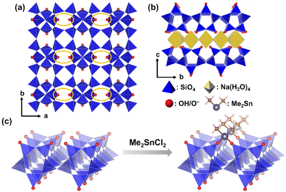 | ||
| Scheme 1 (a) and (b) Structural models of Na-type layered octosilicate and (c) bidentate immobilization of dimethyltin dichloride on the surface of octosilicate. | ||
Methods
Materials
SiO2 (fumed silica (S5130)) was purchased from Sigma-Aldrich. NaOH (97%), SnO (97%), SnO2 (98%), dehydrated pyridine (99.5%), super dehydrated N,N-dimethylformamide (DMF, 99.5%), super dehydrated dichloromethane (DCM, 99.5%), dichloromethane (99.5%), and 6 M HCl solution were purchased from FUJIFILM Wako Pure Chemical Corp. Hexadecyltrimethylammonium chloride (C16TMACl, 95% purity), dimethyltin dichloride (Me2SnCl2, 99%), dichlorodimethylsilane (Me2SiCl2, 98%), and dimethyltin oxide (DMTO, 95%) were purchased from Tokyo Chemical Industry. Co., Ltd (TCI). Acetone (99.0%) and hexane (99.0%) were purchased from Kanto Chemical Co., Inc. All the reagents were used without further purification.Preparation of layered Na-octosilicate and ion-exchange with C16TMACl
Na-Oct and hexadecyltrimethylammonium ion-exchanged octosilicate (C16TMA-Oct) were synthesized following the previous reports.45,46 Fumed silica, NaOH, and deionized water were mixed at a molar ratio of 4![[thin space (1/6-em)]](https://www.rsc.org/images/entities/char_2009.gif) :1:25.8 in a Teflon beaker, and the mixture was aged for 1 h. Hydrothermal treatment was conducted in a Teflon-sealed autoclave at 100 °C for 4 weeks. The product was washed with deionized water and air-dried at 45 °C to obtain Na-Oct. The characterization data for Na-Oct are shown in the ESI (Fig. S1–S3 and Tables S1, S2†). Na-Oct (1.5 g) was dispersed in 100 mL of 0.1 M aqueous solution of C16TMACl and stirred at room temperature for 24 h. After centrifuging the suspension, the precipitate was washed twice with deionized water. Finally, the product was vacuum-dried at room temperature to obtain C16TMA-Oct. The characterization data for C16TMA-Oct are shown in the ESI (Fig. S1–S4 and Tables S1, S2†).
:1:25.8 in a Teflon beaker, and the mixture was aged for 1 h. Hydrothermal treatment was conducted in a Teflon-sealed autoclave at 100 °C for 4 weeks. The product was washed with deionized water and air-dried at 45 °C to obtain Na-Oct. The characterization data for Na-Oct are shown in the ESI (Fig. S1–S3 and Tables S1, S2†). Na-Oct (1.5 g) was dispersed in 100 mL of 0.1 M aqueous solution of C16TMACl and stirred at room temperature for 24 h. After centrifuging the suspension, the precipitate was washed twice with deionized water. Finally, the product was vacuum-dried at room temperature to obtain C16TMA-Oct. The characterization data for C16TMA-Oct are shown in the ESI (Fig. S1–S4 and Tables S1, S2†).
Grafting of dimethyltin dichloride on C16TMA-Oct
C16TMA-Oct (0.2 g) was dried in a Schlenk flask under vacuum heating at 120 °C for 3 h. After cooling to 100 °C and introducing dried N2, DMF (10 mL) and Me2SnCl2 were added, and the mixture was stirred at 100 °C for 2 d. The reaction was performed without adding a base such as pyridine to trap HCl. Me2SnCl2 was added at 0.1, 0.25, 0.5, and 10 equivalents (8, 20, 41, and 811 mg, respectively) against a pair of the reaction sites (SiOH/SiO−) on the octosilicate surface. The products were separated by centrifugation (5000 rpm, 5 min), washed three times with acetone, and dried overnight under reduced pressure. The samples were named Me2Sn-Oct_X (X = 0.1, 0.25, 0.5, and 10), where X represents the equivalents of Me2SnCl2.Silylation of C16TMA-Oct with Me2SiCl2
C16TMA-Oct (0.2 g) in a Schlenk flask was dried by vacuum heating at 120 °C for 3 h. Dichloromethane (10 mL), pyridine (5 mL), and Me2SiCl2 (0.44 mL) were added under the N2 atmosphere, and the mixture was stirred at room temperature for 1 d under a nitrogen atmosphere. The silylating agent was 10 equivalents each for the pair of reaction sites (SiOH/SiO−) on the octosilicate surface. The product was separated by centrifugation (5000 rpm, 5 min), washed three times with dichloromethane, and dried overnight under reduced pressure. This sample is denoted as Me2Si-Oct.Synthesis of proton exchanged octosilicate and heat treatment in DMF
The following reference samples were prepared for the detailed characterization of the products using solid-state 29Si NMR. According to previous reports,47,48 protonated octosilicates (H-Oct) can be synthesized by treating Na-Oct with aqueous HCl. Na-Oct (2.5 g) was dispersed in 0.1 M HCl aq. (250 mL) in a beaker and stirred at room temperature for 2 d. The resulting suspension was centrifuged, and the supernatant was removed. The resulting solid was washed twice with deionized water and dried to obtain H-Oct as a white powder. The characterization data for H-Oct are shown in the ESI (Fig. S1–S3 and Tables S1, S2†).For comparison with dimethyltin-modified samples, H-Oct was treated under the same conditions: 0.1 g H-Oct and 10 mL DMF were stirred at 100 °C for 2 d. The samples were washed three times with acetone and dried under reduced pressure. This sample was named H-Oct heat.
Characterization
The X-ray diffraction (XRD) patterns were obtained by a parallel method using a Rigaku RINT-Ultima III powder diffractometer (Cu Kα, λ = 0.15418 nm, 40 kV, 40 mA). Solid-state NMR spectra were recorded on a JEOL JNM-ECX400 spectrometer. Samples were packed in 4 mm zirconia sample tubes and spun at 6 kHz. 13C cross-polarization (CP)/magic-angle spinning (MAS) NMR was measured at a resonance frequency of 99.6 MHz with a recycle delay of 10 s and contact time of 5 ms. 29Si MAS NMR was measured at a resonance frequency of 78.6 MHz, with a 90° pulse and a recycle delay of 500 s. Chemical shifts for 13C and 29Si nuclei were referenced to hexamethylbenzene (![[C with combining low line]](https://www.rsc.org/images/entities/b_char_0043_0332.gif) H3) at 17.4 ppm and polydimethylsilane at −33.8 ppm, respectively, as external standards. Fourier transform infrared (FT-IR) spectra were obtained using the KBr method on an FT/IR-6100 spectrometer (JASCO). Carbon, hydrogen, and nitrogen contents were measured using a CHN corder-type MT-5 (Yanaco). The heating and oxidation temperatures (conc. 15% O2) and temperature at the reduction furnaces were 950, 850, and 550 °C, respectively. The analysis was conducted by A-Rabbit-Science Japan Co., Ltd. The amounts of Si, Na, and Sn were determined using inductively coupled plasma optical emission spectrometry (ICP-OES) (Agilent Technologies, Agilent 5100). Samples were prepared using a melting method with Li2B4O7 as the flux. High-resolution scanning electron microscopy (HR-SEM) images were obtained using an S-5500 microscope (Hitachi High Technologies Co.) at an accelerating voltage of 1 kV. Transmission electron microscopy (TEM), high-angle annular dark-field scanning transmission electron microscopy (HAADF-STEM), and STEM-energy dispersive X-ray spectroscopy (EDS) were performed using a JEM-1400Flash microscope (JEOL) at an accelerating voltage of 120 kV. STEM-EDS mapping was performed using a JEOL JED-2300 T detector. XPS spectra were measured using a JPS-9010MX (JEOL) spectrometer using Mg Kα excitation. The C 1p peak at the binding energy of 284.7 eV was used as a reference. Diffuse reflectance (DR) UV–Vis spectra were recorded on a V-660 spectrometer (JASCO) using a BaSO4 plate as the reference. Sn K-edge XAFS analyses were conducted at the public beamline BL01B1 of SPring-8 at the Japan Synchrotron Radiation Research Institute.49 The incident X-rays were monochromatized using a Si(311) double-crystal monochromator. The photon energy was calibrated at the inflection point of the Sn K-edge X-ray absorption near-edge structure (XANES) spectrum of the Sn metal foil to 29194.99 eV. The powdered samples were diluted with an appropriate amount of boron nitride (BN), pressed into pellets, and used for XAFS measurement. Sn K-edge XAFS spectra were analyzed using xTunes software.50 After normalization, Fourier-transformation (FT) of k3-weighted χ spectra in the k range of 3.0–14.0 Å−1 was performed to obtain the FT-EXAFS spectra. The curve fitting analysis for samples was conducted in the range of 1.2–1.9 Å using a FEFF8 program.51 Density functional theory (DFT) calculations for the structural refinement of Me2Sn-Oct and DMTO were performed using the BIOVIA Materials Studio software. The CASTEP module was used with the GGA-PBE functional.52 The energy tolerance was 2.0 × 10⁻⁵ eV per atom, force tolerance was 0.05 eV Å−1, maximum stress was 0.1 GPa, and displacement tolerance was 0.002 Å. The partial structural model was displayed using the VESTA software.53
H3) at 17.4 ppm and polydimethylsilane at −33.8 ppm, respectively, as external standards. Fourier transform infrared (FT-IR) spectra were obtained using the KBr method on an FT/IR-6100 spectrometer (JASCO). Carbon, hydrogen, and nitrogen contents were measured using a CHN corder-type MT-5 (Yanaco). The heating and oxidation temperatures (conc. 15% O2) and temperature at the reduction furnaces were 950, 850, and 550 °C, respectively. The analysis was conducted by A-Rabbit-Science Japan Co., Ltd. The amounts of Si, Na, and Sn were determined using inductively coupled plasma optical emission spectrometry (ICP-OES) (Agilent Technologies, Agilent 5100). Samples were prepared using a melting method with Li2B4O7 as the flux. High-resolution scanning electron microscopy (HR-SEM) images were obtained using an S-5500 microscope (Hitachi High Technologies Co.) at an accelerating voltage of 1 kV. Transmission electron microscopy (TEM), high-angle annular dark-field scanning transmission electron microscopy (HAADF-STEM), and STEM-energy dispersive X-ray spectroscopy (EDS) were performed using a JEM-1400Flash microscope (JEOL) at an accelerating voltage of 120 kV. STEM-EDS mapping was performed using a JEOL JED-2300 T detector. XPS spectra were measured using a JPS-9010MX (JEOL) spectrometer using Mg Kα excitation. The C 1p peak at the binding energy of 284.7 eV was used as a reference. Diffuse reflectance (DR) UV–Vis spectra were recorded on a V-660 spectrometer (JASCO) using a BaSO4 plate as the reference. Sn K-edge XAFS analyses were conducted at the public beamline BL01B1 of SPring-8 at the Japan Synchrotron Radiation Research Institute.49 The incident X-rays were monochromatized using a Si(311) double-crystal monochromator. The photon energy was calibrated at the inflection point of the Sn K-edge X-ray absorption near-edge structure (XANES) spectrum of the Sn metal foil to 29194.99 eV. The powdered samples were diluted with an appropriate amount of boron nitride (BN), pressed into pellets, and used for XAFS measurement. Sn K-edge XAFS spectra were analyzed using xTunes software.50 After normalization, Fourier-transformation (FT) of k3-weighted χ spectra in the k range of 3.0–14.0 Å−1 was performed to obtain the FT-EXAFS spectra. The curve fitting analysis for samples was conducted in the range of 1.2–1.9 Å using a FEFF8 program.51 Density functional theory (DFT) calculations for the structural refinement of Me2Sn-Oct and DMTO were performed using the BIOVIA Materials Studio software. The CASTEP module was used with the GGA-PBE functional.52 The energy tolerance was 2.0 × 10⁻⁵ eV per atom, force tolerance was 0.05 eV Å−1, maximum stress was 0.1 GPa, and displacement tolerance was 0.002 Å. The partial structural model was displayed using the VESTA software.53
Results & discussion
The powder XRD patterns of C16TMA-Oct and Me2Sn-Oct_X (X = 0.1, 0.25, 0.5, and 10) samples are shown in Fig. 1. C16TMA-Oct (Fig. 1(a)) exhibited a diffraction peak at 2θ = 3.18° (d = 2.79 nm) corresponding to the basal spacing and the in-plane (400) peak of octosilicate at 2θ = 49.4° (d = 0.184 nm). The basal spacings of Me2Sn-Oct_0.1, _0.25, _0.5, and _10 (Fig. 1(b)–(e)) were 2.79, 1.23, 1.08, and 1.18 nm, respectively. Although the d value of Me2Sn-Oct_0.1 was nearly unchanged from that of C16TMA-Oct, the d values of Me2Sn-Oct_0.25, _0.5, and _10 became much smaller, indicating the elimination of C16TMA+, which is consistent with the results of the elemental analysis and solid-state 13C NMR described below. For Me2Sn-Oct_X, the (400) peak gradually shifts to 48.5° (d = 0.187 nm) with increasing the X value. These shifts suggest the in-plane lattice expansion of the octosilicate owing to the introduction of dimethyltin groups. This is similar to the shifting of the (302) peak of the dealuminated BEA-type zeolite to a lower angle because of the framework expansion due to the introduction of Sn species into the silanol nest.54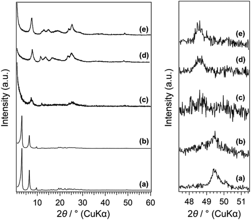 | ||
| Fig. 1 (A) Powder XRD patterns of (a) C16TMA-Oct, (b) Me2Sn-Oct_0.1, (c) Me2Sn-Oct_0.25, (d) Me2Sn-Oct_0.5, and (e) Me2Sn-Oct_10. | ||
The FT-IR spectra of C16TMA-Oct and Me2Sn-Oct_X are shown in Fig. 2(A). C16TMA-Oct (Fig. 2(A)(a)) showed the bands attributed to CH2 asymmetric and symmetric stretching vibrations and CH3 asymmetric and symmetric stretching vibrations of the alkyl groups at 2920, 2850, 2950, and 2870 cm−1, respectively.55 In addition, a band attributed to the Si–OH stretching vibrations on the layer surface was observed at 960 cm−1.56 For Me2Sn-Oct_X (Fig. 2(A)(b)–(e)), the intensities of the C–H stretching vibrations were gradually weakened with increasing X, suggesting the elimination of the C16TMA cations. In the spectra of Me2Sn-Oct_0.5 and Me2Sn-Oct_10 (Fig. 2(A)(d) and (e)), the small bands at 540 and 560 cm−1 were attributed to Sn–C stretching vibrations.57–59 For Me2Sn-Oct_X (Fig. 2(A)(b)–(e)), the band of Si–OH groups (960 cm−1) decreased from that of C16TMA-Oct. A similar decrease was observed upon silylation,46 suggesting that a condensation reaction occurred between the SnCl and SiOH groups. These results suggest the immobilization of methyltin groups on the layer surfaces.
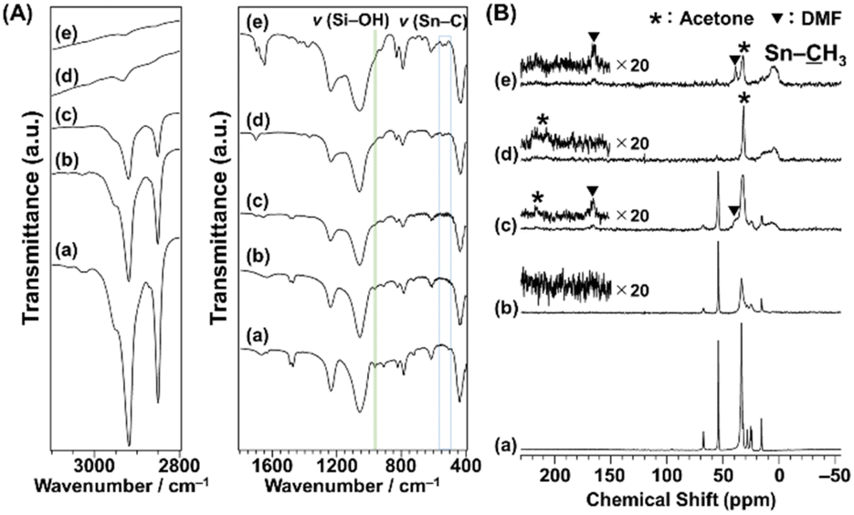 | ||
| Fig. 2 (A) FT-IR spectra and (B) 13C CP/MAS NMR spectra of (a) C16TMA-Oct, (b) Me2Sn-Oct_0.1, (c) Me2Sn-Oct_0.25, (d) Me2Sn-Oct_0.5, and (e) Me2Sn-Oct_10. | ||
The FT-IR spectra of Me2Sn-Oct_X (X = 0.25, 0.5, and 10; Fig. 2(A)(c)–(e)) showed an absorption band at ∼1700 cm−1, which was attributed to the C![[double bond, length as m-dash]](https://www.rsc.org/images/entities/char_e001.gif) O stretching vibration of acetone. For Me2Sn-Oct_10 (Fig. 2(A)(e)), a sharp absorption band was observed at ∼1650 cm−1, which can be attributed to the CO stretching vibration of DMF. These results indicated that the solvent used for the reaction and washing remained. Compared with the CO stretching vibrations of neat acetone and DMF, the CO bands were observed at lower wavenumbers, suggesting interactions between the carbonyl groups and interlayer silanol groups or immobilized alkyltin groups.60,61 Although further drying at 120 °C under vacuum was performed for Me2Sn-Oct_10, these solvent molecules could not be removed (Fig. S5†).
O stretching vibration of acetone. For Me2Sn-Oct_10 (Fig. 2(A)(e)), a sharp absorption band was observed at ∼1650 cm−1, which can be attributed to the CO stretching vibration of DMF. These results indicated that the solvent used for the reaction and washing remained. Compared with the CO stretching vibrations of neat acetone and DMF, the CO bands were observed at lower wavenumbers, suggesting interactions between the carbonyl groups and interlayer silanol groups or immobilized alkyltin groups.60,61 Although further drying at 120 °C under vacuum was performed for Me2Sn-Oct_10, these solvent molecules could not be removed (Fig. S5†).
The 13C CP/MAS NMR spectra of C16TMA-Oct and Me2Sn-Oct_X (X = 0.1, 0.25, 0.5, and 10) are shown in Fig. 2(B). The assignments of the signals of C16TMA-Oct are shown in the ESI (Fig. S4†). The spectra of Me2Sn-Oct_X (Fig. 2(B)(b)–(e)) show that the signals derived from the C16TMA cations gradually decrease with increasing X. The C16TMA cations were nearly eliminated by adding 0.5 equivalent of Me2SnCl2. This result is reasonable because when Me2SnCl2 reacts with a SiOH/SiO−(C16TMA+) pair to form two Sn–O–Si bonds, C16TMACl and HCl are generated. The generated HCl converts the unreacted SiO−(C16TMA+) site to SiOH and subsequently generates additional C16TMACl (ESI, Scheme S1†). C16TMACl was finally removed by washing with acetone. In addition, the spectra of Me2Sn-Oct_X (X = 0.25, 0.5, and 10; Fig. 2(B)(c)–(e)) show broad signals at ∼10 ppm, attributable to the methyl groups attached to Sn (H3–Sn).62 The signal broadening may have been caused by dipole coupling from the Sn atoms. Furthermore, Me2Sn-Oct_X exhibited signals attributed to acetone (H3: 31.7 ppm, O: 210 ppm) and DMF (H3: 39 ppm and 33 ppm, O: 165 ppm), which agreed with the FT-IR results.
The results of the elemental analyses are listed in Table 1. The N/Si ratio of C16TMA-Oct and Me2Sn-Oct_X (X = 0.1, 0.25, and 0.5) gradually decreased with increasing X (0.26→0.18→0.07→0.01), which was owing to the removal of C16TMA cations. The N/Si ratio of Me2Sn-Oct_10 (0.08) was higher than that of Me2Sn-Oct_0.5 (0.01). This was probably owing to the remaining DMF, as indicated by the FT-IR and solid-state 13C NMR analyses. The tin content of Me2Sn-Oct_X gradually increased with increasing X, indicating a correlation between the elimination of interlayer C16TMA cations and modification with Sn. The Sn/Si ratios of Me2Sn-Oct_X (X = 0.1, 0.25, 0.5, and 10) were 0.03, 0.08, 0.13, and 0.14, respectively (Table 1). Assuming the bidentate immobilization of dimethyltin on all octosilicate reaction sites, the Sn/Si ratio should be 0.25. Therefore, the degrees of modification with Sn of Me2Sn-Oct_X (X = 0.1, 0.25, 0.5, and 10) were 12%, 32%, 52%, and 56%, respectively.
| Sample name | C/wt% | N/wt% | Si/wt% | Sn/wt% | N/Si ratio | Sn/Si ratio |
|---|---|---|---|---|---|---|
| C16TMA-Oct | 36.8 | 2.4 | 18.7 | — | 0.26 | — |
| Me2Sn-Oct_0.1 | 30.7 | 2.0 | 22.1 | 3.2 | 0.18 | 0.03 |
| Me2Sn-Oct_0.25 | 13.4 | 1.0 | 27.9 | 9.8 | 0.07 | 0.08 |
| Me2Sn-Oct_0.5 | 7.1 | 0.1 | 30.9 | 16.6 | 0.01 | 0.13 |
| Me2Sn-Oct_10 | 7.3 | 1.1 | 28.7 | 17.1 | 0.08 | 0.14 |
SEM, TEM, and EDS mapping images of Me2Sn-Oct_X (X = 0.1, 0.25, 0.5, and 10) are shown in Fig. 3. All samples exhibited an octosilicate-derived platelet morphology with a uniform distribution of Sn, suggesting the grafting of Sn species on the entire surface of the silicate layers. The EDS mapping image of Me2Sn-Oct_0.1 also showed that a larger amount of Sn species was present near the edge region of the plate. EDS quantitative analysis (Fig. 3, right) confirmed that the Sn/Si ratio increased with increasing X in Me2Sn-Oct_X. This trend in the local observations is consistent with the overall elemental analysis using ICP-OES and CHN described above.
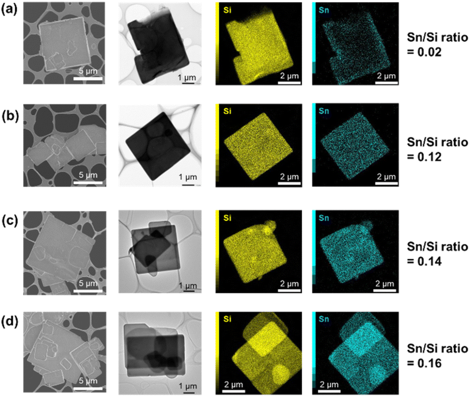 | ||
| Fig. 3 Electron microscopy images of (a) Me2Sn-Oct_0.1, (b) Me2Sn-Oct_0.25, (c) Me2Sn-Oct_0.5, and (d) Me2Sn-Oct_10. From left to right: SEM images, TEM images, EDS mapping images, and Sn/Si ratios by EDS quantitative analysis. | ||
Fig. 4 shows the solid-state 29Si MAS NMR spectra of C16TMA-Oct and Me2Sn-Oct_X (X = 0.1, 0.25, or 0.5). For C16TMA-Oct (Fig. 4(a)), signals attributed to Q3 (![[S with combining low line]](https://www.rsc.org/images/entities/b_char_0053_0332.gif)
![[i with combining low line]](https://www.rsc.org/images/entities/b_char_0069_0332.gif) (OSi)3OH/O−) and Q4 ((OSi)4) sites appeared at −100 and −111 ppm, respectively, with an integral intensity ratio of 1:1.45 For the spectra of Me2Sn-Oct_X (Fig. 4(b)–(d)), the integral intensity ratio of the Q3 signal to the Q4 signal decreased, and new signals appeared at −103 and −107 ppm. For Me2Sn-Oct_10, the original Q3 signal disappeared, and signals were observed at −103, −107, and −110 ppm.
(OSi)3OH/O−) and Q4 ((OSi)4) sites appeared at −100 and −111 ppm, respectively, with an integral intensity ratio of 1:1.45 For the spectra of Me2Sn-Oct_X (Fig. 4(b)–(d)), the integral intensity ratio of the Q3 signal to the Q4 signal decreased, and new signals appeared at −103 and −107 ppm. For Me2Sn-Oct_10, the original Q3 signal disappeared, and signals were observed at −103, −107, and −110 ppm.
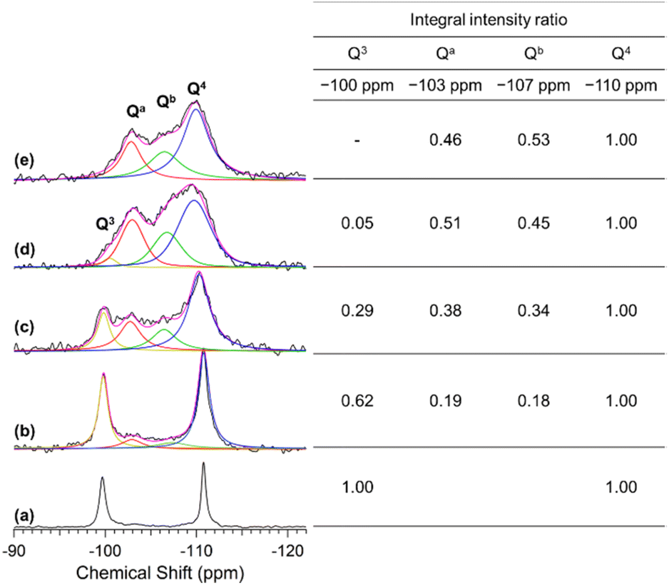 | ||
| Fig. 4 29Si MAS NMR spectra of (a) C16TMA-Oct, (b) Me2Sn-Oct_0.1, (c) Me2Sn-Oct_0.25, (d) Me2Sn-Oct_0.5, and (e) Me2Sn-Oct_10. Black lines are the original spectra, pink lines are the fitting spectra, yellow lines indicate the Q3 signals at −100 ppm, red lines indicate the Qa signal at −103 ppm, green lines indicate the Qb signal at −107 ppm, and blue lines indicate the Q4 signal at −110 ppm. The inserted table shows the relative integral intensity ratio of each signal. | ||
Herein, the signals at −103 and −107 ppm were named Qa and Qb, respectively. The relative integral intensity ratios of the Q3, Qa, and Qb signals to those of the Q4 signal are listed in the inset table of Fig. 4. For Me2Sn-Oct_X (X = 0.1, 0.25, and 0.5), the sum of Q3, Qa, and Qb was approximately equal to Q4, indicating that the ratio of (Qa + Qb) coincided with the decrease in the ratio of the Q3 signal to that of C16TMA-Oct. Therefore, Qa and Qb are related to silicon environments that emerge from the reactions of the original Q3 environments. As described earlier, the introduction of methyltin groups and the elimination of C16TMA+ were confirmed. Accordingly, these two new environments were assumed to be dimethyltin-modified sites (Si(OSi)3O–Sn) and the confronting disilanol sites (Si(OSi)3OH/Si(OSi)3OH).
29Si MAS NMR analysis of the proton-exchanged octosilicate (H-Oct) was performed to obtain information on the chemical shifts of the silanol sites. A Q3 signal was observed at −98 ppm for H-Oct (ESI, Fig. S6(a)†). H-Oct_heat, obtained by stirring H-Oct in DMF at 100 °C for 2 d followed by washing with acetone (see Experimental section), showed that the Q3 signal shifted to −103 ppm (ESI, Fig. S6(b)†). The retention of acetone in the interlayer spaces of H-Oct_heat was confirmed using 13C CP/MAS NMR (ESI, Fig. S7†) and XRD (ESI, Fig. S8†), which was consistent with the literature.47 The Q3 signal of H-Oct partially shifts to higher fields by heating.63 Based on these facts, the Qa signal observed at −103 ppm for Me2Sn-Oct_X is attributed to the confronting silanol sites ((OSi)3OH/(OSi)3OH). The other signal at −107 ppm (Qb) is attributed to dimethyltin-modified sites ((OSi)3O–Sn). Such a high-field shift of the 29Si NMR signal owing to bonding with organotin is consistent with a previous report.64 Furthermore, because the integral intensity ratio of Qb corresponds to the amount of Sn-modified Si, the degree of modification with Sn (Qb × 100) can be estimated. The degrees of Sn modification for Me2Sn-Oct_X (X = 0.1, 0.25, 0.5, and 10) were 18%, 34%, 45%, and 53%, respectively, which were in good agreement with those calculated from the Sn/Si ratio by elemental analysis.
With increasing amounts of Me2SnCl2, the elimination of nearly all C16TMA cations and a decrease in basal spacing were observed (Fig. 1 and 2), indicating that the dimethyltin groups were grafted not only on the outer surface of the layer but also between the layers. In the EDS mapping image of Me2Sn-Oct_0.1 (Fig. 3(a)), the tin species were more clearly visible in the edge region of the octosilicate platelet crystal, suggesting that the dimethyltin immobilization reaction progressed gradually from the edge of the crystal. However, the degree of modification with dimethyltin reached a limit of approximately 50% (Table 1 and Fig. 4), which was lower than the degree of silylation using silane analogues (88% for Me2SiCl2, Fig. S9 and Table S3 in ESI†).
The powder XRD data (Fig. 1) show that the diffraction angles of the 400 planes decreased with increasing amounts of Sn modification, reaching a minimum of 48.5°. The diffraction angle of the 400 planes of Me2Si-Oct (ESI, Fig. S10†) was 48.6°, indicating that the lattice expansion was similar to that caused by a lower degree of modification with the dimethyltin species (Me2Sn-Oct_10). It is assumed that the confronting SiOH/SiO− groups of octosilicate are distorted by grafting dimethyltin groups because the Sn–O bond is slightly longer than the Si–O bond.65 The introduction of dimethyltin species into the reaction sites causes in-plane framework expansion, narrowing the distance between the adjacent confronting SiOH/SiO− groups. Consequently, the decrease in the reactivity of the narrowed sites prevents the introduction of additional dimethyltin species (ESI, Scheme S2(a)†). Therefore, the silicate layers of Me2Sn-Oct_10 consist of alternate dimethyltin-modified and nonmodified confronting SiOH/SiO− sites (ESI, Scheme S2(b)†).
UV–Vis (Fig. 5(A)) measurements were performed to investigate the local environment of Sn in the samples. For the spectra of Me2Sn-Oct_X, a shoulder band was observed at 220 nm. This absorption band was attributed to O → Sn LMCT (ligand to metal charge transfer), generally observed for tin-containing zeolites and mesoporous silica.66,67 For the UV–Vis spectrum of dimethyltin oxide (DMTO) (Fig. S11†), some broad absorption bands were observed at 200–250 nm, whereas a relatively sharp absorption band was observed for Me2Sn-Oct_X. Thus, the extra-framework DMTO derived from the hydrolytic condensation of Me2SnCl2, an undesired reaction during the synthesis, was negligible. Me2Sn-Oct_X (X = 0.25, 0.5, and 10) and H-Oct_heat exhibited absorption bands at ∼255 nm. This band was attributed to the n → π* transition of acetone, although it is typically observed at ∼280 nm.68 The interaction between the carbonyl groups of acetones and surface silanol groups might cause this shift towards a lower wavelength.
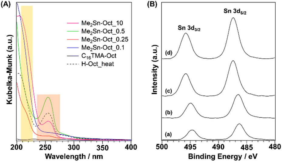 | ||
| Fig. 5 (A) UV–Vis spectra of C16TMA-Oct, Me2Sn-Oct_0.1, Me2Sn-Oct_0.25, Me2Sn-Oct_0.5, Me2Sn-Oct_10, and H-Oct_heat. (B) XPS profiles of (a) Me2Sn-Oct_0.1, (b) Me2Sn-Oct_0.25, (c) Me2Sn-Oct_0.5, and (d) Me2Sn-Oct_10. | ||
XPS analysis of Me2Sn-Oct_X was also performed (Fig. 5(B)). In the spectrum of Me2Sn-Oct_0.1 (Fig. 5(B)(a)), Sn-derived peaks were observed at 486.2 eV (Sn 3d5/2) and 494.7 eV (Sn 3d3/2), which gradually shifted towards higher energies up to 487.4 and 495.8 eV with increasing X (Fig. 5(B)(a)–(d)). The binding energy regions of these peaks correspond to tetravalent Sn. The Sn 3d5/2 peak of the Sn(OSi)4 species in tin-containing zeolites appears at ∼487.5 eV.69 The Sn 3d5/2 peak for Me2Sn-Oct_0.1 appears on the low binding energy side because the central Sn is electron-rich owing to the replacement of two of the four coordinating oxygen atoms with more electron-donating carbon atoms. Shifts in the binding energy towards higher energies for Me2Sn-Oct_X were observed with increasing amounts of tin. This may be associated with the in-plane lattice expansion of the silicate layers, as confirmed by powder XRD. The distortion around Sn became more prominent as grafting was progressed. This distortion may increase the binding energy.70
Further detailed information on the local structure of Sn in the samples was obtained using Sn K-edge XAFS analysis. The XANES spectra are shown in Fig. 6(A). The values of absorption edge in each spectrum are listed in Table S4 in ESI.† Sn foil, SnO, SnO2, and DMTO were used as the reference samples. DMTO is a five-coordinate organotin compound consisting of Sn bonded to two methyl groups and three oxygen atoms. The two Sn–O–Sn chains interact with each other. Thus, DMTO has a ladder-like structure.71,72 DMTO was used as a reference sample for dimethyltin compounds. The absorption edges of SnO and SnO2 were at 29196.8 and 29200.6 eV, respectively. The absorption edge of DMTO was at 29198.6 eV, indicating a shift in the absorption edge towards lower energies than that of SnO2. This shift was owing to the partial substitution of the Sn4+ surroundings from oxygen atoms to carbon atoms with lower electronegativity, which was consistent with the XPS results. The absorption edges of Me2Sn-Oct_X were shifted to lower energy compared to those of DMTO, suggesting lower coordination numbers. In addition, the values of the absorption edges remained unchanged regardless of the value of X, that is, the degree of dimethyltin modification. This suggested that the local environments of the dimethyltin species were similar.
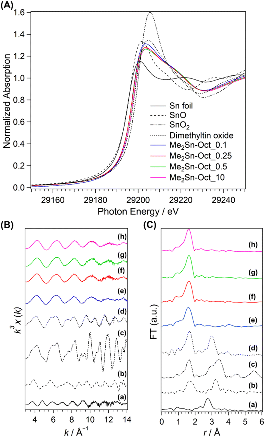 | ||
| Fig. 6 (A) XANES spectra, (B) EXAFS spectra, and (C) FT-EXAFS spectra of (a) Sn foil, (b) SnO, (c) SnO2, (d) dimethyltin oxide (DMTO), (e) Me2Sn-Oct_0.1, (f) Me2Sn-Oct_0.25, (g) Me2Sn-Oct_0.5, and (h) Me2Sn-Oct_10. | ||
The k3-weighted Sn K-edge EXAFS spectra and FT-EXAFS spectra obtained in the range k = 3–14 Å−1 are shown in Fig. 6(B) and (C). The coordination atoms, coordination numbers, and bond distances around Sn were estimated by curve-fitting the FT-EXAFS spectra. For the reference samples (Sn foil, SnO, SnO2, and DMTO; Fig. 6(C)(a)–(d)), the second coordination sphere peaks attributed to Sn–Sn scattering were observed between 2.2 and 3.9 Å. By contrast, no peaks are observed for Me2Sn-Oct_X (Fig. 6(C)(e)–(h)). Elements with different backscattering factors in EXAFS vibrations are less likely to scatter at longer distances. Therefore, the Sn–Si scattering of Sn-containing zeolites with isolated Sn(IV) in the silica framework is very small.73,74 In the current system, Sn–Si scattering was reasonably absent. In addition, the absence of peaks in this region indicates that only a few Sn–O–Sn bonds were present, indicating that condensation of dimethyltin dichloride did not occur.
The data calculated by curve fitting the FT-EXAFS data are provided in Table 2. The parameters for Sn foil, SnO, and SnO2 were in good agreement with the previous report.75 The model of DMTO (ESI, Fig. S12†) was prepared following the previously proposed double-stranded ladder-like structures.71,72 Although the first coordination sphere consists of oxygen and carbon bonded to Sn, each peak was curve-fitted as Sn–O bonds because these elements have indistinguishable backscattering factors. Therefore, the scattering path is described as Sn–O (C). The first coordination sphere for DMTO had 4.7 coordinating atoms (oxygen or carbon) with distances of 2.08 Å, respectively. Moreover, the peak appearing in the second coordination sphere was the scattering derived from Sn–Sn at a distance of 3.27 Å. Thus, the double-chain ladder structure of dimethyltin oxide proposed in a previous report71,72 was verified. The Sn–O (C) bond distances for Me2Sn-Oct_X were 2.03 or 2.04 Å, which was shorter than that of DMTO. The Sn–O bond distance in isolated SnO4 in zeolites is shorter than that in SnO2 because the coordination number is reduced from 6 to 4.73 The shorter Sn–O (C) bonds for the dimethyltin-modified octosilicate than that for DMTO with five-coordinated Sn can be explained by the four-coordinated state of the dimethyltin species on the silicate layers. Because the presence of dimethyltin species on the interlayer surfaces has been confirmed by other analyses above, the four-coordinated Sn species suggest the dipodally grafted dimethyltin species. Therefore, the curve fitting results for Me2Sn-Oct_X are consistent with a dimethyltin-grafted octosilicate structure model (Fig. S13†). Thus, the Sn K-edge XAFS measurements of Me2Sn-Oct_X revealed the local structure of the dimethyltin groups.
| Sample name | Patha | N | r (Å) |
σ
2d (Å2) |
R factore |
|---|---|---|---|---|---|
| a Path denotes the scattering path of the photoelectrons included in the model. b N denotes the coordination number corresponding to the scattering path. c r denotes bond length. d σ 2 denotes the Debye–Waller factor. e R factor = (∑(k3χdata(k) − k3χfit(k))2)1/2/(∑(k3χdata(k))2)1/2. | |||||
| Sn foil | Sn–Sn | 4.0 ± 0.3 | 3.00 ± 0.04 | 0.011 ± 0.005 | 8.0 |
| SnO | Sn–O | 4.3 ± 0.4 | 2.17 ± 0.05 | 0.009 ± 0.006 | 10.8 |
| Sn–Sn | 3.0 ± 0.3 | 3.51 ± 0.04 | 0.006 ± 0.004 | 6.4 | |
| SnO2 | Sn–O | 5.6 ± 0.2 | 2.04 ± 0.02 | 0.003 ± 0.002 | 8.7 |
| Sn–Sn | 2.3 ± 0.1 | 3.18 ± 0.02 | 0.003 ± 0.002 | 10.5 | |
| Sn–Sn | 7.6 ± 0.2 | 3.74 ± 0.02 | 0.004 ± 0.002 | ||
| DMTO | Sn–O (C) | 4.7 ± 0.2 | 2.08 ± 0.03 | 0.006 ± 0.003 | 7.3 |
| Sn–Sn | 2.6 ± 0.2 | 3.27 ± 0.03 | 0.005 ± 0.002 | 8.7 | |
| Me2Sn-Oct_0.1 | Sn–O (C) | 4.4 ± 0.3 | 2.04 ± 0.04 | 0.006 ± 0.004 | 9.7 |
| Me2Sn-Oct_0.25 | Sn–O (C) | 4.0 ± 0.2 | 2.04 ± 0.03 | 0.005 ± 0.003 | 10.6 |
| Me2Sn-Oct_0.5 | Sn–O (C) | 4.0 ± 0.2 | 2.03 ± 0.03 | 0.005 ± 0.003 | 10.6 |
| Me2Sn-Oct_10 | Sn–O (C) | 4.0 ± 0.2 | 2.03 ± 0.03 | 0.005 ± 0.003 | 10.4 |
Conclusions
The interlayer silanol groups of the layered octosilicate were modified with Me2SnCl2, and the isolated dimethyltin species were grafted onto the surface. The degree of modification increased with increasing amounts of dimethyltin dichloride. When 10 equivalents of Me2SnCl2 were added to the reaction sites, approximately 50% of the total silanol sites of the octosilicate were modified. It was assumed that the larger Sn relative to the confronting silanol site caused the expansion of the framework. Accordingly, a possible structure was proposed in which every other silanol site is modified with dimethyltin groups. This report shows that well-defined metal species can be immobilized on regularly arranged reaction sites on the surfaces of crystalline layered polysilicates. Furthermore, it is notable that the arrangement of the immobilized dimethyltin groups was distinctly different from that of the dimethylsilyl groups when silane analogues were used. The use of layered polysilicates as crystalline silica supports for isolated alkyltin catalysts will become more promising.Author contributions
M. Y. designed the study, performed the experiments and material characterization, and wrote the manuscript. T. H. and S. Y. supported the XAFS measurements and analysis. A. S. and K. K. supervised the study. All authors discussed the results, commented on the manuscript, and approved the final version.Conflicts of interest
There are no conflicts to declare.Acknowledgements
We gratefully acknowledge Dr M. Koike, Dr T. Matsuno, Dr K. Muramatsu, Mr K. Fujino, Mr T. Hayashi, Mr Y. Miyamoto, Ms H. Katayama, Mr T. Hattori, Mr T. Houya, Mr T. Mizuno, Ms N. Hori, Mr T. Iwakami (Waseda University) for their assistance with sample preparation, measurement, and fruitful discussions. We acknowledge Dr N. Hanzawa (Kagami Memorial Research Institute for Materials Science and Technology, Waseda University), Dr T. Shibue, (Material Characterization Central Laboratory, Waseda University76), Dr R. Takahashi (Environmental Safety Center, Waseda University), Mr H. Sampei, Ms A. Motomura, Ms A. Shigemoto, and Prof. Y. Sekine (Waseda University) for the XPS, TEM, NMR, ICP-OES, and XAFS analyses. This work was the result of using research equipments (JNM-ECX400 (C1025), ICP-OES (D1001), JPS-9010MX (G1010), S-5500 microscope (G1028), JEM-1400Flash (G1032), and RINT-Ultima III (G1035)) shared in the MEXT Project for promoting public utilization of advanced research infrastructure (program for supporting construction of core facilities) (grant number JPMXS0440500023). The synchrotron radiation experiments were performed at the BL01B1 of SPring-8 with the approval of the Japan Synchrotron Radiation Research Institute (JASRI) (Proposal No. 2022B0305). This work was partly supported by a grant-in-aid for scientific research (B) (grant number 23H02051). M. Y. is grateful to the JST SPRING (grant number JPMJSP2128) and Grant-in-Aid for JSPS Research Fellowship for Young Scientist (grant number 22J13718).References
- M. K. Samantaray, E. Pump, A. Bendjeriou-Sedjerari, V. D'Elia, J. D. A. Pelletier, M. Guidotti, R. Psaro and J. M. Basset, Chem. Soc. Rev., 2018, 47, 8403–8437 RSC.
- C. Copéret, A. Comas-Vives, M. P. Conley, D. P. Estes, A. Fedorov, V. Mougel, H. Nagae, F. Núnez-Zarur and P. A. Zhizhko, Chem. Rev., 2016, 116, 323–421 CrossRef PubMed.
- C. Copéret, F. Allouche, K. W. Chan, M. P. Conley, M. F. Delley, A. Fedorov, I. B. Moroz, V. Mougel, M. Pucino, K. Searles, K. Yamamoto and P. A. Zhizhko, Angew. Chem., Int. Ed., 2018, 57, 6398–6440 CrossRef PubMed.
- J. M. Thomas, R. Raja and D. W. Lewis, Angew. Chem., Int. Ed., 2005, 44, 6456–6482 CrossRef CAS PubMed.
- B. Zhang, T. Fan, N. Xie, G. Nie and H. Zhang, Adv. Sci., 2019, 6, 1901787 CrossRef CAS PubMed.
- S. L. Suib, J. Přech, E. Szaniawska and J. Čejka, Chem. Rev., 2023, 123, 877–917 CrossRef CAS PubMed.
- M. Shamzhy, M. Opanasenko, P. Concepción and A. Martínez, Chem. Soc. Rev., 2019, 48, 1095–1149 RSC.
- L. T. Zhuravlev, Colloids Surf., A, 2000, 173, 1–38 CrossRef CAS.
- A. Rimola, D. Costa, M. Sodupe, J. F. Lambert and P. Ugliengo, Chem. Rev., 2013, 113, 4216–4313 CrossRef CAS PubMed.
- Y. Ishizaka, N. Arai, K. Matsumoto, H. Nagashima, K. Takeuchi, N. Fukaya, H. Yasuda, K. Sato and J. Choi, Chem. – Eur. J., 2021, 27, 12069–12077 CrossRef CAS PubMed.
- P. Li, G. Liu, H. Wu, Y. Liu, J. G. Jiang and P. Wu, J. Phys. Chem. C, 2011, 115, 3663–3670 CrossRef CAS.
- W. N. P. Van Der Graaff, G. Li, B. Mezari, E. A. Pidko and E. J. M. Hensen, ChemCatChem, 2015, 7, 1152–1160 CrossRef CAS.
- P. Peng, X.-H. Gao, Z.-F. Yan and S. Mintova, Natl. Sci. Rev., 2020, 7, 1726–1742 CrossRef PubMed.
- N. Takahashi and K. Kuroda, J. Mater. Chem., 2011, 21, 14336–14353 RSC.
- D. Sangian, Y. Ide, Y. Bando, A. E. Rowan and Y. Yamauchi, Small, 2018, 14, 1800551 CrossRef PubMed.
- N. Tsunoji, Y. Ide, Y. Yagenji, M. Sadakane and T. Sano, ACS Appl. Mater. Interfaces, 2014, 6, 4616–4621 CrossRef CAS PubMed.
- E. Doustkhah, S. Rostamnia, N. Tsunoji, J. Henzie, T. Takei, Y. Yamauchi and Y. Ide, Chem. Commun., 2018, 54, 4402–4405 RSC.
- M. Ogawa, S. Okutomo and K. Kuroda, J. Am. Chem. Soc., 1998, 120, 7361–7362 CrossRef CAS.
- Y. Ide, N. Kagawa, M. Sadakane and T. Sano, Chem. Commun., 2013, 49, 9027–9029 RSC.
- Y. Asakura, Y. Sakamoto and K. Kuroda, Chem. Mater., 2014, 26, 3796–3803 CrossRef CAS.
- T. Yanagisawa, K. Kuroda and C. Kato, Bull. Chem. Soc. Jpn., 1988, 61, 3743–3745 CrossRef CAS.
- A. Shimojima, D. Mochizuki and K. Kuroda, Chem. Mater., 2001, 13, 3603–3609 CrossRef CAS.
- D. Mochizuki, A. Shimojima, T. Imagawa and K. Kuroda, J. Am. Chem. Soc., 2005, 127, 7183–7191 CrossRef CAS PubMed.
- Y. Asakura, Y. Matsuo, N. Takahashi and K. Kuroda, Bull. Chem. Soc. Jpn., 2011, 84, 968–975 CrossRef CAS.
- Y. Ide, G. Ozaki and M. Ogawa, Langmuir, 2009, 25, 5276–5281 CrossRef CAS PubMed.
- T. Selvam, A. Inayat and W. Schwieger, Dalton Trans., 2014, 43, 10365–10387 RSC.
- S. Osada, A. Iribe and K. Kuroda, Chem. Lett., 2013, 42, 80–82 CrossRef CAS.
- P. Loch, D. Schuchardt, G. Algara-Siller, P. Markus, K. Ottermann, S. Rosenfeldt, T. Lunkenbein, W. Schwieger, G. Papastavrou and J. Breu, Sci. Adv., 2022, 8, eabn9084 CrossRef CAS PubMed.
- N. Tsunoji, M. V. Opanasenko, M. Kubů, J. Čejka, H. Nishida, S. Hayakawa, Y. Ide, M. Sadakane and T. Sano, ChemCatChem, 2018, 10, 2536–2540 CrossRef CAS.
- N. Tsunoji, H. Nishida, Y. Ide, K. Komaguchi, S. Hayakawa, Y. Yagenji, M. Sadakane and T. Sano, ACS Catal., 2019, 9, 5742–5751 CrossRef CAS.
- A. Corma, U. Díaz, V. Fornés, J. L. Jordá, M. Domine and F. Rey, Chem. Commun., 1999, 779–780 RSC.
- N. A. Grosso-Giordano, C. Schroeder, A. Okrut, A. Solovyov, C. Schöttle, W. Chassé, N. Marinković, H. Koller, S. I. Zones and A. Katz, J. Am. Chem. Soc., 2018, 140, 4956–4960 CrossRef CAS PubMed.
- C. Nédez, A. Theolier, F. Lefebvre, A. Choplin, J. M. Basset and J. F. Joly, J. Am. Chem. Soc., 1993, 115, 722–729 CrossRef.
- A. Corma, M. T. Navarro and M. Renz, J. Catal., 2003, 219, 242–246 CrossRef CAS.
- L. Wang, J. Zhang, X. Wang, B. Zhang, W. Ji, X. Meng, J. Li, D. S. Su, X. Bao and F. S. Xiao, J. Mater. Chem. A, 2014, 2, 3725–3729 RSC.
- R. A. De Jesus, P. Da Conceição, J. P. V. Da Silva, N. S. Brainer, S. M. P. Meneghetti and M. R. Meneghetti, J. Braz. Chem. Soc., 2019, 30, 1976–1987 CAS.
- X. X. Wang, L. Veyre, F. Lefebvre, J. Patarin and J. M. Basset, Microporous Mesoporous Mater., 2003, 66, 169–179 CrossRef CAS.
- A. Saidi, W. Al Maksoud, M. K. Samantaray, E. Abou-Hamad and J. M. Basset, Chem. Commun., 2020, 56, 13401–13404 RSC.
- P. Ferrini, J. Dijkmans, R. De Clercq, S. Van de Vyver, M. Dusselier, P. A. Jacobs and B. F. Sels, Coord. Chem. Rev., 2017, 343, 220–255 CrossRef CAS.
- J. Cervantes, R. Zárraga and C. Salazar-Hernández, Appl. Organomet. Chem., 2012, 26, 157–163 CrossRef CAS.
- M. Aresta, A. Dibenedetto, F. Nocito and C. Pastore, J. Mol. Catal. A: Chem., 2006, 257, 149–153 CrossRef CAS.
- J. George, Y. Patel, S. M. Pillai and P. Munshi, J. Mol. Catal. A: Chem., 2009, 304, 1–7 CrossRef CAS.
- N. Rabiee, M. Safarkhani and M. M. Amini, Rev. Inorg. Chem., 2019, 39, 13–45 CrossRef CAS.
- B. Tang, W. Dai, G. Wu, N. Guan, L. Li and M. Hunger, ACS Catal., 2014, 4, 2801–2810 CrossRef CAS.
- D. Mochizuki, S. Kowata and K. Kuroda, Chem. Mater., 2006, 18, 5223–5229 CrossRef CAS.
- M. Yatomi, M. Koike, N. Rey, Y. Murakami, S. Saito, H. Wada, A. Shimojima, D. Portehault, S. Carenco, C. Sanchez, C. Carcel, M. Wong Chi Man and K. Kuroda, Eur. J. Inorg. Chem., 2021, 2021, 1836–1845 CrossRef CAS.
- M. Borowski, O. Kovalev and H. Gies, Microporous Mesoporous Mater., 2008, 107, 71–80 CrossRef CAS.
- S. Kiba, T. Itagaki, T. Nakato and K. Kuroda, J. Mater. Chem., 2010, 20, 3202–3210 RSC.
- T. Uruga, H. Tanida, Y. Yoneda, K. Takeshita, S. Emura, M. Takahashi, M. Harada, Y. Nishihata, Y. Kubozono, T. Tanaka, T. Yamamoto, H. Maeda, O. Kamishima, Y. Takabayashi, Y. Nakata, H. Kimura, S. Goto and T. Ishikawa, J. Synchrotron Radiat., 1999, 6, 143–145 CrossRef CAS PubMed.
- H. Asakura, S. Yamazoe, T. Misumi, A. Fujita, T. Tsukuda and T. Tanaka, Radiat. Phys. Chem., 2020, 175, 108270 CrossRef CAS.
- A. L. Ankudinov, B. Ravel, J. J. Rehr and S. D. Conradson, Phys. Rev. B: Condens. Matter Mater. Phys., 1998, 58, 7565–7576 CrossRef CAS.
- J. P. Perdew, K. Burke and M. Ernzerhof, Phys. Rev. Lett., 1996, 77, 3865–3868 CrossRef CAS PubMed.
- K. Momma and F. Izumi, J. Appl. Crystallogr., 2011, 44, 1272–1276 CrossRef CAS.
- W. Dai, Q. Lei, G. Wu, N. Guan, M. Hunger and L. Li, ACS Catal., 2020, 10, 14135–14146 CrossRef CAS.
- C. Bisio, F. Carniato, G. Paul, G. Gatti, E. Boccaleri and L. Marchese, Langmuir, 2011, 27, 7250–7257 CrossRef CAS PubMed.
- T. D. Courtney, C. C. Chang, R. J. Gorte, R. F. Lobo, W. Fan and V. Nikolakis, Microporous Mesoporous Mater., 2015, 210, 69–76 CrossRef CAS.
- T. Tanaka, Y. Matsumura, R. Okawara, Y. Musya and S. Kinumaki, Bull. Chem. Soc. Jpn., 1968, 41, 1497–1501 CrossRef CAS.
- L. Pellerito, G. Dia, A. Gianguzza, M. A. Girasolo, E. Rizzarelli and R. Purrello, Polyhedron, 1987, 6, 1639–1645 CrossRef CAS.
- M. C. Tobin, J. Mol. Spectrosc., 1961, 5, 65–71 CrossRef.
- C. Zhang, Z. Ren, Z. Yin, L. Jiang and S. Fang, Spectrochim. Acta, Part A, 2011, 81, 598–603 CrossRef CAS PubMed.
- M. Koike, Y. Asakura, Y. Kuroda, H. Wada, A. Shimojima and K. Kuroda, Clay Sci., 2018, 22, 1–11 CAS.
- M. Gopalakrishnan and N. Palanisami, RSC Adv., 2016, 6, 1760–1768 RSC.
- G. Borbély, H. G. Karge, W. Schwieger, A. Brandt and K.-H. Bergk, Clays Clay Miner., 1991, 39, 490–497 CrossRef.
- Y. Matsubara, W. Konishi, T. Sugizaki and O. Moriya, J. Polym. Sci., Part A: Polym. Chem., 2001, 39, 2125–2133 CrossRef CAS.
- J. Beckmann and K. Jurkschat, Coord. Chem. Rev., 2001, 215, 267–300 CrossRef CAS.
- J. Dijkmans, M. Dusselier, W. Janssens, M. Trekels, A. Vantomme, E. Breynaert, C. Kirschhock and B. F. Sels, ACS Catal., 2016, 6, 31–46 CrossRef CAS.
- J. Dijkmans, J. Demol, K. Houthoofd, S. Huang, Y. Pontikes and B. Sels, J. Catal., 2015, 330, 545–557 CrossRef CAS.
- J. D. Koch, J. Gronki and R. K. Hanson, J. Quant. Spectrosc. Radiat. Transfer, 2008, 109, 2037–2044 CrossRef CAS.
- J. Dijkmans, M. Dusselier, D. Gabriëls, K. Houthoofd, P. C. M. M. Magusin, S. Huang, Y. Pontikes, M. Trekels, A. Vantomme, L. Giebeler, S. Oswald and B. F. Sels, ACS Catal., 2015, 5, 928–940 CrossRef CAS.
- M. Sun, Y. Su, C. Du, Q. Zhao and Z. Liu, RSC Adv., 2014, 4, 30820–30827 RSC.
- R. Okawara, Proc. Chem. Soc., 1964, 383 Search PubMed.
- R. K. Harris and A. Sebald, J. Organomet. Chem., 1987, 331, C9–C12 CrossRef CAS.
- S. R. Bare, S. D. Kelly, W. Sinkler, J. J. Low, F. S. Modica, S. Valencia, A. Corma and L. T. Nemeth, J. Am. Chem. Soc., 2005, 127, 12924–12932 CrossRef CAS PubMed.
- A. Al-Nayili, K. Yakabi and C. Hammond, J. Mater. Chem. A, 2016, 4, 1373–1382 RSC.
- T. Hara, M. Hatakeyama, A. Kim, N. Ichikuni and S. Shimazu, Green Chem., 2012, 14, 771–777 RSC.
- C. Izutani, D. Fukagawa, M. Miyasita, M. Ito, N. Sugimura, R. Aoyama, T. Gotoh, T. Shibue, Y. Igarashi and H. Oshio, J. Chem. Educ., 2016, 93, 1667–1670 CrossRef CAS.
Footnote |
| † Electronic supplementary information (ESI) available. See DOI: https://doi.org/10.1039/d3dt03231k |
| This journal is © The Royal Society of Chemistry 2023 |