
 Open Access Article
 This Open Access Article is licensed under a Creative Commons Attribution-Non Commercial 3.0 Unported Licence
Mg-doped SrTiO3 photocatalyst with Ag–Co cocatalyst for enhanced selective conversion of CO2 to CO using H2O as the electron donor†
Takechi
Nakamoto
 a,
Shoji
Iguchi
*a,
Shimpei
Naniwa
a,
Tsunehiro
Tanaka
ab and
Kentaro
Teramura
*abc
a,
Shoji
Iguchi
*a,
Shimpei
Naniwa
a,
Tsunehiro
Tanaka
ab and
Kentaro
Teramura
*abc
aDepartment of Molecular Engineering, Graduate School of Engineering, Kyoto University, Kyoto-daigaku Katsura, Nishikyo-ku, Kyoto 615-8510, Japan. E-mail: iguchi.shoji.4k@kyoto-u.ac.jp; teramura.kentaro.7r@kyoto-u.ac.jp; Fax: +81 75 383 2561; Tel: +81 75 383 2559
bElements Strategy Initiative for Catalysts & Batteries (ESICB), Kyoto University, 1-30 Goryo-Ohara, Nishikyo-ku, Kyoto 615-8245, Japan
cFukui Institute for Fundamental Chemistry, Kyoto University, Takano Nishibiraki-cho 34-4, Sakyo-ku, Kyoto 606-8103, Japan
First published on 4th July 2023
Abstract
Photocatalytic conversion of CO2 by H2O is a promising method for solving energy and environmental problems. In this context, efficient photocatalysts that facilitate the selective conversion of CO2 to the value-added chemical CO are essential. In this study, for the first time in the literature, we used an Mg-doped SrTiO3 photocatalyst (Mg–SrTiO3) for the photocatalytic conversion of CO2 to CO using H2O as the electron donor under monochromatic UV-light irradiation at 365 nm. Compared to pristine SrTiO3, Mg–SrTiO3, which was prepared via a flux method, exhibited dramatically enhanced conversion of CO2 to CO in the presence of an Ag–Co cocatalyst. Moreover, the selectivity toward CO evolution was >99%, which indicates suppression of the unnecessary and competitive H2 evolution. Scanning electron microscopy of Mg–SrTiO3 revealed edge-shaved cubic particles, which were correlated to the anisotropic distribution of photogenerated electrons and holes and the consequent enhancement of photocatalytic activity. Furthermore, the Mg-doping temperature and amount used to prepare Mg–SrTiO3 influenced the substitution of Ti4+ sites by Mg2+ in the bulk of SrTiO3, thereby affecting the CO evolution. The apparent quantum efficiency of optimal Mg–SrTiO3 in the photocatalytic conversion of CO2 was determined to be 0.05%.
Introduction
Climate change is a serious and escalating problem globally.1,2 It is primarily attributed to the greenhouse effect of atmospheric CO2.3 The concentration of atmospheric CO2 reached over 400 ppm by 2013 and has been predicted to further increase in the near future.4 Among the many approaches to reduce CO2 emissions,5–7 photocatalysis has attracted significant attention owing to several reasons.In 1972, Honda and Fujishima reported that photoirradiation of TiO2 electrodes can shift the anode potential for water oxidation in electrochemical water splitting to a more negative value.8 This study promoted the development of photocatalysis for degradation of organic compounds and overall water splitting. A promising photocatalyst that is widely used for generating clean energy is the perovskite oxide SrTiO3.9–12 Domen et al. reported that Al-doped SrTiO3 (Al–SrTiO3) is an excellent photocatalyst for efficient photocatalytic H2O splitting,13 where it showed a near 100% internal quantum efficiency. This efficiency was attributed to the particle shape of the photocatalyst, which promotes charge separation, as evidenced by an electrical simulation.14 Yamakata et al. demonstrated that doping Na+ into SrTiO3 improved the photocatalytic activity for water splitting. They concluded that the generated oxygen vacancies act as trapping sites for the photogenerated electrons, consequently extending their lifetimes.15,16
Even though photocatalytic water splitting has been extensively studied, the photocatalytic conversion of CO2 by water, which is known as “artificial photosynthesis”, requires further improvement.17–19 Conversion of the emitted CO2 into value-added chemicals such as CO, HCOOH, CH3OH, and CH4 using solar light could promote a sustainable society built on energy recycling.20,21 In particular, CO is considered as a useful and important product, as it can be converted into a liquefied hydrocarbon, which is a raw material in core industries, through the Fischer–Tropsch process.22 Our research group has previously reported the photocatalysts Ag/SrO/Ta2O5, Ag/La2Ti2O7, Ag/ZnTa2O6, and Ag/SrNb2O6 for the selective conversion of CO2 by water under UV-light irradiation (<300 nm).23–26 These photocatalysts use water as both an electron donor and a proton source, which is favourable because water is abundant, cheap, easy to use, and non-toxic. Moreover, we demonstrated that Ag/Sr2KTa5O15 and Ag/ZnGa2O4/Ga2O3 facilitated a sufficiently high selectivity toward CO2 conversion via the complete suppression of H2 evolution.26,27 Even though H2 evolution (H+/H2: −0.41 V vs. NHE at pH = 7.0) proceeds preferentially over CO2 reduction owing to the more negative standard redox potential of the latter reaction (CO2/CO: −0.51 V vs. NHE at pH = 7.0),28 the modification of photocatalysts with appropriate cocatalysts enabled selective CO formation.29–31 Furthermore, a recent study reported that, Ag–Co/Al–SrTiO3 is the most effective photocatalyst for the photocatalytic conversion of CO2 under an irradiation of 365 nm.32 This was attributed to the bandgap energy of Al-doped SrTiO3 (3.2 eV), which is smaller than those of the previously reported Ga-based and Ta-based photocatalysts.33–35 The Ag–Co dual cocatalyst was more effective than single Ag and Co cocatalysts for CO evolution when paired with Al–SrTiO3, where Ag and Co are active sites for CO2 conversion and H2O oxidation, respectively.36,37 The formation rate of CO over Ag–Co/Al–SrTiO3 was approximately seven times higher than that of Ag/Al–SrTiO3.32,38 In a continuation of our efforts to identify effective photocatalysts for the photocatalytic conversion of CO2 to CO in water, in this study, we investigated metals other than Al as dopants for SrTiO3 and optimized the doping process. Subsequently, we evaluated the photocatalytic activity of the doped SrTiO3 photocatalysts in the conversion of CO2 to CO under UV-LED-light irradiation at 365 nm.
Experimental section
Preparation of the photocatalysts
The perovskite-structured SrTiO3 photocatalyst was fabricated via a previously reported solid-state method.39 SrCO3 (21 mmol) and TiO2 (20 mmol) were ground for 15 min using a mortar and pestle, and the mixture was transferred to an alumina crucible to calcine at 1373 K for 10 h in air. The resulting powder was washed three times with hot ultrapure water and dried overnight at room temperature. BaTiO3 and CaTiO3 were synthesised via the same procedure using BaCO3 and CaCO3 as precursors, respectively.M-doped SrTiO3 (M–SrTiO3, M = Al, Zn, Li, Mn, W, Ca, Y, and Mg) was synthesised via a flux method.36 SrCl2 flux (100 mmol) was added to a mixture of the prepared SrTiO3 (10 mmol) and a metal oxide (0.4 mmol). The mixture was ground for 15 min using a mortar and pestle, transferred to an yttria crucible, and calcined at 1418 K for 15 h. The obtained powder was washed three times with hot ultrapure water and dried overnight at 353 K. Next, we fabricated a series of Mg–SrTiO3 photocatalysts, termed as Mg–SrTiO3_x K, Mg–SrTiO3_y h, and Mg(z)–SrTiO3, where x, y, and z are the calcination temperature (x = 1118, 1268, 1318, 1368, and 1418 K), calcination time (y = 1, 10, 15, and 20 h), and molar ratio (mol%) of Mg to Ti (z = 0, 2, 4, 8, 24, and 100), respectively. Mg-doped BaTiO3 (Mg–BaTiO3) and Mg-doped CaTiO3 (Mg–CaTiO3) were also fabricated via the same method using BaCl2 and CaCl2 as fluxes, respectively.
Loading of the cocatalysts
A conventional chemical reduction (CR) method was used to load Ag and Co cocatalysts onto the surface of M–SrTiO3.36 M–SrTiO3 (0.75 g) was dispersed in ultrapure water (50 mL), and the suspension was maintained at 353 K. Aqueous solutions of AgNO3 (0.1 M, 0.695 mL), Co(NO3)2 (0.1 M, 0.347 mL), and NaH2PO2 (0.4 M, 1.5 mL) were added to the suspension while continuously stirring. The resultant suspension was maintained at 353 K for 1.5 h. The solid residue was collected via vacuum filtration and dried overnight at room temperature to obtain the Ag–Co/M–SrTiO3 powder.Furthermore, MgO/SrTiO3 and MgO/Al–SrTiO3 were prepared via an impregnation method as reference materials.32 SrTiO3 or Al–SrTiO3 (0.92 g) was added to an acetone solution of Mg(NO3)2·6H2O (0.051 g). The solvent was completely evaporated by heating the suspension while vigorously stirring, and the resultant powder was calcined at 773 K for 5 h.
Characterization
The crystalline properties of the fabricated photocatalysts were evaluated by X-ray diffraction (XRD) using a Rigaku SmartLab SE equipped with CuKα radiation (λ = 0.154 nm). UV-visible diffuse reflectance spectroscopy (UV-vis DRS) was performed using the JASCO V-670 spectrometer equipped with an integrating sphere. A BaSO4 plate was used as a standard reflection sample. Scanning electron microscopy (SEM) images were obtained at an acceleration voltage of 3.0 kV using a field-emission scanning electron microscope (SU-8220, Hitachi High-Technologies) equipped with an energy-dispersive X-ray spectroscopy (EDS) unit for elemental mapping. X-ray photoelectron spectroscopy (XPS) was performed by an X-ray photoelectron spectrometer (ESCA 3400, Shimadzu Corp.) at various Ar sputtering times (emission 70 mA; Accel HT: 0.6 kV). Inductively coupled plasma optical emission spectrometry (ICP-OES, iCAP7400, Thermo Fisher Scientific, Inc.) was used to determine the atomic content of Sr, Ti, and Mg in Mg–SrTiO3.Photocatalytic reactions
The photocatalytic conversion of CO2 by H2O as the electron donor was conducted using an external irradiation-type reaction vessel (Scheme S1†) in a quasi-flowing batch system. Ag–Co/M–SrTiO3 (0.2 g) was dispersed in a 0.1 M aqueous solution of NaHCO3 (200 mL). A high purity CO2 gas (99.999%) was bubbled into the resultant suspension at a flow rate of 60 mL min−1 for 1 h to remove the dissolved air in the reaction solution. The suspension was then irradiated using a monochromatic UV-LED lamp at 365 nm (IRS-1000, CELL System Co., Ltd., Japan) with continuous CO2 gas flow at a flow rate of 30 mL min−1. The generated gases were analysed using online gas chromatographs equipped with a thermal conductivity detector (TCD-GC; GC-8A, Shimadzu Corporation, Japan; Ar carrier gas; molecular sieve 5A column) and a flame-ionisation detector with a methanizer (FID-GC; GC-8A, Shimadzu Corporation, Japan; N2 carrier gas; Shincarbon ST column). The CO selectivity and balance of consumed electrons and holes (e−/h+) were calculated using eqn (1) and (2) as follows:| CO selectivity (%) = RCO/(RCO + RH2) × 100 | (1) |
| e−/h+ = (2RCO + 2RH2)/4RO2 | (2) |
The apparent quantum efficiency (AQE, %) of the photocatalysts was calculated from the formation rate of the product and the light intensity measured using a power meter (OPHIR Photonics, A Newport Company) using eqn (3).
| AQE (%) = (number of reacted electrons/number of incident photons) × 100 | (3) |
| Number of reacted electrons = 2 × (RCO + RH2) × 10−6 × NA | (4) |
Results and discussion
Fig. S1† shows the XRD patterns and UV-vis DR spectra of M–SrTiO3 (M = Al, Zn, Li, Mn, W, Ca, Y, or Mg). Well-ordered diffraction patterns corresponding to the perovskite structure were observed in all the cases. Moreover, the dopant metals did not alter the absorption wavelength, whereas the DR spectrum of Mn–SrTiO3 shows a typical absorption corresponding to the d–d transition of the Mn species. Fig. 1 shows the formation rates of gaseous products (CO, H2, and O2) and selectivity toward CO evolution in the photocatalytic conversion of CO2 in the presence of the Ag–Co/M–SrTiO3 photocatalysts (M = Al, Zn, Li, Mn, W, Ca, Y, and Mg) upon photoirradiation for 1 h. Zn–SrTiO3, Li–SrTiO3, Mn–SrTiO3, W–SrTiO3, Ca–SrTiO3, and Y–SrTiO3 exhibited extremely low photocatalytic activities for the conversion of CO2, whereas Al–SrTiO3 and Mg–SrTiO3 showed moderate activities. Mg–SrTiO3 exhibited the highest activity for CO evolution, which has been observed as a CO formation rate of ∼20 μmol h−1. A previous study reported that Al–SrTiO3 showed excellent activity in the presence of Rh/Cr2O3/CoOOH cocatalysts during photocatalytic H2 evolution.14 However, H2 evolution was drastically suppressed (0.055 μmol h−1) in the presence of Ag–Co/Mg–SrTiO3, where the selectivity toward CO evolution was >99%, indicating that Mg-doping into SrTiO3 improved the photocatalytic activity for the conversion of CO2. Moreover, the CO formation rate over Mg–SrTiO3 was two or more times higher than that over the previously reported Al–SrTiO3 photocatalyst.32 Furthermore, stoichiometric O2 evolution (8.9 μmol h−1) was observed in the presence of Mg–SrTiO3 (e−/h+ = 1.1), suggesting that H2O acts as both an electron donor and a proton source for the photocatalytic conversion of CO2 in water. Fig. S2† shows the photocatalytic activities of Ag–Co/Mg–ATiO3 photocatalysts (A = Ba, Ca, and Sr) in the conversion of CO2. Mg–BaTiO3 and Mg–CaTiO3 showed extremely low and no photocatalytic activity, respectively, indicating that other perovskite photocatalysts are not effective in this reaction. Therefore, we focused on the effect of Mg-doping into SrTiO3 on the photocatalytic conversion of CO2 in water. | ||
| Fig. 1 Formation rates of CO (red), H2 (blue), and O2 (green) and the selectivity toward CO evolution (black diamond) in the photocatalytic conversion of CO2 in H2O over the pristine and the doped Ag–Co/M–SrTiO3 photocatalysts (M = Al, Zn, Li, Mn, W, Ca, Y, and Mg). Reaction conditions: amount of photocatalyst: 0.2 g; Ag loading: 1 wt%; Co loading: 0.3 wt%; volume of reaction solution (H2O): 0.2 L; additive: 0.1 M NaHCO3; CO2 flow rate: 30 mL min−1; light source: monochromatic LED lamp at 365 nm; photoirradiation time: 1 h. | ||
The XRD patterns of pristine SrTiO3, Mg–SrTiO3, and Ag–Co/Mg–SrTiO3 (Fig. 2(A-1)) correspond to the pure phase of the perovskite structure belonging to the Pm3m (211) space group (ICSD 23076). Peaks corresponding to the Ag or Co species were not observed in the XRD pattern of Ag–Co/Mg–SrTiO3, suggesting that the Ag–Co cocatalyst was loaded on the surface of Mg–SrTiO3 with high dispersion. The full width at half maximum (FWHM) of the peaks of crystalline SrTiO3, Mg–SrTiO3, and Ag–Co/Mg–SrTiO3 attributed to the (110) phase (2θ = ∼32°) were 0.11°, 0.094°, and 0.10°, respectively. Flux treatment during Mg doping resulted in slight crystal growth and enhanced the crystalline character of SrTiO3. However, we believe that these new characteristics of the photocatalyst did not enhance the photocatalytic activity because flux-treated SrTiO3 did not show significant CO evolution in the absence of MgO, as shown in Fig. 6. The peak at approximately 2θ = 67.8° in the pattern of Mg–SrTiO3, shown in Fig. 2(A-2), is ascribed to the (220) phase. This peak shifted to a lower angle than that of SrTiO3, which indicates that replacing Ti4+ in the bulk of SrTiO3 with Mg2+ dopant extends the lattice plane distance. The ionic radii of six-coordinated Sr2+, Ti4+, and Mg2+ were 1.18, 0.605, and 0.720 Å, respectively.40 Furthermore, the Mg 2p XPS spectra of Mg–SrTiO3 obtained at various Ar sputtering times confirmed that the Mg2+ ions were doped into the bulk of SrTiO3 (Fig. S3†).
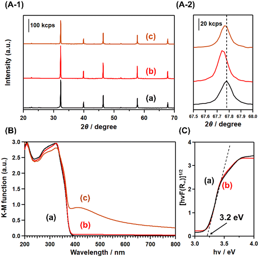 | ||
| Fig. 2 (A-1) X-ray diffraction (XRD) patterns, (B) UV-visible diffuse reflectance (UV-vis DR) spectra, and (C) Tauc plots of (a) pristine SrTiO3, (b) Mg–SrTiO3, and (c) Ag–Co/Mg–SrTiO3. (A-2) is the magnified view of (a)–(c) in (A-1). | ||
Fig. 2(B) shows the UV-vis DR spectra of SrTiO3, Mg–SrTiO3, and Ag–Co/Mg–SrTiO3. The absorption edge of SrTiO3 was estimated to be 390 nm, which confirms the suitability of the monochromatized UV-LED irradiation at 365 nm. The UV-vis DR spectrum of Mg–SrTiO3 ((b) in Fig. 2(B)) shows that Mg2+ doping did not influence the absorption wavelengths of SrTiO3. The Tauc plot (Fig. 2(C)) revealed that the bandgap energies of pristine SrTiO3 and Mg–SrTiO3 were 3.2 eV, which is consistent with previous reports.41–43 In the case of Ag–Co/Mg–SrTiO3 ((c) in Fig. 2(B)), a broad absorption was observed in the visible-light region. Typically, Ag demonstrates plasmonic absorption in the visible-light region in its metal form (with a valence number of 0) and in its nanoparticle form. Therefore, we attributed this broad peak to the plasmonic absorption of Ag nanoparticles,44 which confirms that Ag was loaded on Mg–SrTiO3 in the form of nanoparticles. Moreover, the Ag K-edge XANES spectrum of Ag–Co/Mg–SrTiO3 is in good agreement with that of the Ag foil, indicating that Ag particles with a valence number of 0 were loaded onto Mg–SrTiO3 as a cocatalyst (Fig. S4†).
The SEM image in Fig. 3(a) shows that pristine SrTiO3 has an irregular shape. In the absence of an Mg dopant, the shape of the SrTiO3 particle is regulated by its calcination with SrCl2 flux, resulting in cubic particles with {100} facets (Fig. 3(b)). However, Mg–SrTiO3 has edge-shaved cube particles with {110} facets in addition to the {100} facets, as shown in Fig. 3(c). A similar change was observed for Al–SrTiO3 in previous studies.13,45 Takata et al. have performed calculations to determine the distribution of photogenerated electrons and holes of SrTiO3 in the {100} and {110} facets. They observed that the concentration of electrons around the {100} facets was relatively high, whereas holes were easily transferred to the {110} facets.4 To confirm this anisotropic charge distribution, we investigated the photodeposition of Ag and Co cocatalysts on the surface of Mg–SrTiO3 in this study. As shown in Fig. S5,† the Ag and Co cocatalysts were deposited on the {100} and {110} facets, respectively. This indicates that photoexcited electrons and holes are selectively distributed in Mg–SrTiO3 based on the facets. This distribution suppresses the electron–hole recombination, thus contributing to the high photocatalytic activity. As mentioned previously, we used the CR method to load Ag and Co cocatalysts on Mg–SrTiO3 as it is regarded as the optimal method for the photocatalytic conversion of CO2 (Fig. S6†). As shown in Fig. 3(d), the cocatalysts loaded by the CR method were not facet-selective but were highly dispersed on the surface of the Mg–SrTiO3 particles. The average diameter of the Ag cocatalyst was estimated to be 7.0 nm based on the diameter distribution in the transmission electron microscopy (TEM) images. This diameter is smaller than that of the Ag cocatalysts loaded via the photodeposition and impregnation methods (Fig. S7†).
 | ||
| Fig. 3 Scanning electron microscopy (SEM) images of (a) pristine SrTiO3, (b) flux-treated SrTiO3, (c) Mg–SrTiO3, and (d) Ag–Co/Mg–SrTiO3. | ||
Several previous reports have demonstrated that the modification of photocatalysts with metal oxides or hydroxides such as SrO, Cr(OH)3, Pr(OH)3, and layered double hydroxides, which can provide adsorption sites for CO2, improves the photocatalytic activity in the selective conversion of CO2.23,46–50 However, we observed that the CO formation rate and CO selectivity are higher for Mg–SrTiO3 than those for MgO/SrTiO3 and MgO/Al–SrTiO3 (fabricated via the conventional impregnation method) in the presence of the Ag–Co cocatalyst, as shown in Fig. S8.† These results clearly indicate that the residual MgO or Mg(OH)2 on the surface of Mg–SrTiO3 does not significantly improve the photocatalytic activity. Therefore, Mg2+-doping into the bulk structure of SrTiO3 is essential for good photocatalytic conversion of CO2 in water.
Fig. 4 shows the XRD patterns of the Mg–SrTiO3 fabricated by calcination at 1118, 1268, 1318, 1368, and 1418 K. These diffraction patterns correspond to the perovskite structure of SrTiO3, and no impurity phases were observed in any of the cases. The position of the diffraction peak at 2θ = 68° in Fig. 4(A-2) is assigned to the (220) phase. This peak shifted to a lower angle with increasing calcination temperature, which indicates that Ti4+ in the bulk structure of SrTiO3 was steadily replaced with Mg2+. Therefore, Mg doping into SrTiO3 can be enhanced by increasing the calcination temperature in the flux treatment. As shown in Fig. 5(A), Ag–Co/Mg–SrTiO3_1118 K generated a small amount of CO during the photocatalytic reaction. Mg–SrTiO3_1118 K can be considered as “un-doped” SrTiO3 because 1118 K is lower than the melting point of the SrCl2 flux (1147 K). This is confirmed by the fact that the edge-shaved cubic structure was not observed in the SEM image of Mg–SrTiO3_1118 K (Fig. S9†). Moreover, the CO formation rate drastically improved at the calcination temperature of 1268 K, which is higher than the melting point of the SrCl2 flux. As shown in Fig. 5(B), a clear correlation was observed between the CO formation rate and the XRD peak positions, suggesting that greater doping amounts result in greater photocatalytic activity for the conversion of CO2.
 | ||
| Fig. 4 (A-1) XRD patterns of (a) pristine SrTiO3, (b) Mg–SrTiO3_1118 K, (c) Mg–SrTiO3_1268 K, (d) Mg–SrTiO3_1318 K, (e) Mg–SrTiO3_1368 K, and (f) Mg–SrTiO3_1418 K. (A-2) is the magnified view of (a)–(f) in (A-1). (B) Dependence of calcination temperature on the peak top position of the (220) phase. | ||
 | ||
| Fig. 5 (A) Formation rates of CO (red), H2 (blue), and O2 (green) and the selectivity toward CO evolution (black diamond) in the photocatalytic conversion of CO2 in H2O over Ag–Co/Mg–SrTiO3_x K photocatalysts (x = 1118, 1268, 1318, 1368, and 1418). Reaction conditions: amount of photocatalyst: 0.2 g; Ag loading: 1 wt%; Co loading: 0.3 wt%; volume of reaction solution (H2O): 0.2 L; additive: 0.1 M NaHCO3; CO2 flow rate: 30 mL min−1; light source: monochromatic LED lamp at 365 nm; photoirradiation time: 1 h. (B) Dependence of peak position on CO formation rate. | ||
Fig. S10(A-1)† shows the XRD patterns of Mg–SrTiO3_y h, where y is the calcination time (y = 1, 10, 15, and 20 h) for the doping process at 1418 K. The peak top position of the (220) phase shifted with increasing doping time, as shown in Fig. S10(A-2),† indicating that Mg doping into SrTiO3 is enhanced by prolonging the doping time. Moreover, as shown in Fig. S11(B),† a positive correlation is observed between the photocatalytic activity for the conversion of CO2 to CO and the peak top position of the (220) phase diffraction. These results confirm that the extent of Mg doping via the replacement of Ti4+ sites in SrTiO3 with Mg2+ is a significant parameter for CO evolution.
Fig. S12† shows the XRD pattern of Mg(z)–SrTiO3, where z is the molar ratio (mol%) of the Mg dopant to SrTiO3 (z = 0, 2, 4, 8, 24, and 100). Clear diffraction patterns corresponding to the perovskite structure of SrTiO3 were observed in all cases. However, the diffraction patterns of Mg(0)–SrTiO3 and Mg(2)–SrTiO3 indicate a small impurity phase, which is attributed to Y2O3. This suggests that the Mg–SrTiO3 samples were contaminated with the yttria crucible during their preparation. In contrast, a small diffraction peak corresponding to MgO was observed for Mg(24)–SrTiO3 and Mg(100)–SrTiO3, which is ascribed to excess amounts of the corresponding Mg dopants. The diffraction peak corresponding to the (220) facets of Mg(4)–SrTiO3 appeared at a lower angle than that of the pristine sample, whereas the peak top position of Mg(8)–SrTiO3 slightly shifted to a higher angle than that of Mg(4)–SrTiO3. We attribute the former case to the replacement of Ti4+ sites of SrTiO3 with Mg2+ species and the latter case to the replacement of some Sr2+ sites with Mg2+ species.
Fig. 6 shows the photocatalytic activity of Ag–Co/Mg(z)–SrTiO3 in the conversion of CO2 in water. Ag–Co/Mg(0)–SrTiO3 exhibited negligible activity, and no product evolution was observed. However, the CO formation rate increased with increasing amounts of Mg dopants. The highest CO formation rates were observed for Ag–Co/Mg(4)–SrTiO3 and Ag–Co/Mg(8)–SrTiO3. These rates decreased slightly upon addition of excess Mg dopant, suggesting that 4 mol% of Mg dopant is optimal for CO evolution. Furthermore, our results suggest that the replacement of the Sr2+ sites with Mg2+ species and the presence of precipitated MgO do not influence the photocatalytic activity for the conversion of CO2. Table S1† shows the actual atomic content of Sr, Ti, and Mg in Mg–SrTiO3, Mg–SrTiO3_1268 K, and Mg(2)–SrTiO3 determined by ICP measurements. As we concluded in the above discussion, the formation rate of CO had a good agreement with the amount of Mg doped into SrTiO3.
 | ||
| Fig. 6 Formation rates of CO (red), H2 (blue), and O2 (green) and selectivity toward CO evolution (black diamond) in the photocatalytic conversion of CO2 in H2O over the Ag–Co/Mg(z)–SrTiO3 photocatalysts (z = 0, 2, 4, 8, 24, and 100). Reaction conditions: amount of photocatalyst: 0.2 g; Ag loading: 1 wt%; Co loading: 0.3 wt%; volume of reaction solution (H2O): 0.2 L; additive: 0.1 M NaHCO3; CO2 flow rate: 30 mL min−1; light source: monochromatic LED lamp at 365 nm; photoirradiation time: 1 h. | ||
Fig. S13† shows the results of the control experiments for the photocatalytic conversion of CO2 in water using optimised Ag–Co/Mg–SrTiO3. The reduction of CO2 to CO did not proceed well in the absence of the photocatalyst, photoirradiation, or the NaHCO3 additive. These results clearly indicate that the presence of Ag–Co/Mg–SrTiO3 photocatalyst and NaHCO3 additive under UV-LED photoirradiation significantly enhanced the conversion of CO2 to CO.51 To confirm the origin of the evolved CO in the photocatalytic conversion of CO2 in the presence of Ag–Co/Mg–SrTiO3, we conducted isotope-labelling experiments using 13CO2 gas as the substrate. Fig. 7 shows the gas chromatography-thermal conductivity detector (GC-TCD) chromatogram and the quadrupole mass spectrometer (Q-MS) profiles of m/z = 28 and 29 in the online GC-MS analysis for the photocatalytic conversion of 13CO2. In the TCD-GC chromatogram, H2 and O2 were observed at 2 and 4 min, respectively, in addition to N2 from air. Q-MS analysis of the outlet gas revealed no quantifiable peak at m/z = 28 except for N2 contamination. In contrast, a clear peak appeared at approximately 19 min in the Q-MS profile of m/z = 29, indicating that 13CO was produced from the introduced 13CO2. This isotopic experiment confirmed that 13C-labeled CO (m/z = 29) evolved preferentially over 12CO (m/z = 28). This suggests that the evolved CO gas originated from the CO2 gas bubbled into the suspension. Furthermore, the apparent quantum efficiency (AQE) of optimal Mg–SrTiO3 in the photocatalytic conversion of CO2 using Ag–Co/Mg–SrTiO3 photocatalyst under monochromatic UV-light irradiation (365 nm) was determined to be 0.05% (see ESI† for the details).
 | ||
| Fig. 7 Gas chromatography-thermal conductivity detector (GC-TCD) chromatogram and Q-MS profiles at m/z = 28 and 29 for the photocatalytic conversion of 13CO2 in H2O over Ag–Co/Mg–SrTiO3. Reaction conditions: amount of photocatalyst: 0.2 g; Ag loading: 1 wt%; Co loading: 0.3 wt%; volume of reaction solution (H2O): 0.2 L; additive: 0.1 M NaHCO3; 13CO2 flow rate: 30 mL min−1; light source: monochromatic LED lamp at 365 nm; photoirradiation time: 1.5 h. | ||
Scheme 1 shows the proposed mechanism for the photocatalytic conversion of CO2 over Ag–Co/Mg–SrTiO3 with H2O as the electron donor. As mentioned previously, a Mg–SrTiO3 particle has an edge-shaved cube with exposed {100} and {110} facets. We inferred that the photocatalytic conversion of CO2 to CO occurs at the Ag sites on the {100} facets of Mg–SrTiO3, whereas oxidation of H2O to O2 proceeds at the Co sites on the {110} facets.13,52 As shown in Fig. S14,† highly selective CO formation was observed continuously for 15 h despite the aggregation of the Ag nanoparticles owing to the photoirradiation (Fig. S15†).
 | ||
| Scheme 1 Proposed mechanism of the photocatalytic conversion of CO2 in H2O over Ag–Co/Mg–SrTiO3. | ||
Conclusions
An Mg-doped SrTiO3 photocatalyst (Mg–SrTiO3) was successfully synthesised using a previously reported flux method. Mg–SrTiO3 exhibited excellent photocatalytic activity under monochromatic UV-light irradiation at 365 nm, resulting in selective conversion of CO2 to CO in the presence of Ag–Co cocatalyst. The AQE of this reaction was determined to be 0.05%. Moreover, isotope experiments revealed that the evolved CO originated from gaseous CO2. The CO formation rate drastically improved by doping Mg into SrTiO3. SEM images of Mg–SrTiO3 revealed the presence of edge-shaved cubic particles with {110} facets in addition to {100} facets. This was correlated to the separation of photogenerated carriers and consequent suppression of charge recombination, which dramatically improved the photocatalytic activity for the conversion of CO2 to CO.Author contributions
T. Nakamoto: investigation, writing – original draft preparation; S. Iguchi and S. Naniwa: visualization, writing – editing; T. Tanaka and K. Teramura: visualization, supervision, funding acquisition.Conflicts of interest
There are no conflicts to declare.Acknowledgements
This research was partially supported by the Program for Elements Strategy Initiative for Catalysts and Batteries (ESICB) commissioned by the Ministry of Education, Culture, Sports, Science, and Technology (MEXT) of Japan. This work was also supported by JSPS KAKENHI grants (21H01716 and 22K14541) and a Research Grant against Global Warming from the Ichimura Foundation for New Technology. The XAS measurements were performed at the BL14B2 of SPring-8 with the approval of the Japan Synchrotron Radiation Research Institute (JASRI) (Proposal No. 2022B1885).References
- A. H. Xie, J. P. Zhu, S. C. Kang, X. Qin, B. Xu and Y. C. Wang, Sci. Rep., 2022, 12, 16548 CrossRef CAS PubMed
.
- J. F. B. Mitchell, Rev. Geophys., 1989, 27, 115–139 CrossRef
- P. M. Cox, R. A. Betts, C. D. Jones, S. A. Spall and I. J. Totterdell, Nature, 2000, 408, 184–187 CrossRef CAS PubMed
- Y. Kuzyakov, W. R. Horwath, M. Dorodnikov and E. Blagodatskaya, Soil Biol. Biochem., 2019, 128, 66–78 CrossRef CAS
- P. R. Yaashikaa, P. S. Kumar, S. J. Varjani and A. Saravanan, J. CO2 Util., 2019, 33, 131–147 CrossRef CAS
- M. W. Yuan, M. J. Kummer and S. D. Minteer, Chem. – Eur. J., 2019, 25, 14258–14266 CrossRef CAS PubMed
- M. G. Kibria, J. P. Edwards, C. M. Gabardo, C. T. Dinh, A. Seifitokaldani, D. Sinton and E. H. Sargent, Adv. Mater., 2019, 31, 1807166 CrossRef PubMed
- A. Fujishima and K. Honda, Nature, 1972, 238, 37–38 CrossRef CAS PubMed
- Q. Wang, J. Warnan, S. Rodriguez-Jimenez, J. J. Leung, S. Kalathil, V. Andrei, K. Domen and E. Reisner, Nat. Energy, 2020, 5, 703–710 CrossRef CAS
- Y. Nosaka, S. Takahashi, Y. Mitani, X. Q. Qui and M. Miyauchi, Appl. Catal., B, 2012, 111–112, 636–640 CrossRef CAS
- Z. D. Liu and Z. Ma, Mater. Res. Bull., 2019, 118, 110492 CrossRef CAS
- M. Siebenhofer, A. Viernstein, M. Morgenbesser, J. Fleig and M. Kubicek, Mater. Adv., 2021, 2, 7583–7619 RSC
- Y. Ham, T. Hisatomi, Y. Goto, Y. Moriya, Y. Sakata, A. Yamakata, J. Kubota and K. Domen, J. Mater. Chem. A, 2016, 4, 3027–3033 RSC
- T. Takata, J. Z. Jiang, Y. Sakata, M. Nakabayashi, N. Shibata, V. Nandal, K. Seki, T. Hisatomi and K. Domen, Nature, 2020, 581, 411–414 CrossRef CAS PubMed
- K. Kato, J. Z. Jiang, Y. Sakata and A. Yamakata, ChemCatChem, 2019, 11, 6349–6354 CrossRef CAS
- J. Z. Jiang, K. Kato, H. Fujimori, A. Yamakata and Y. Sakata, J. Catal., 2020, 390, 81–89 CrossRef CAS
- J. J. Yang, Y. Zhang, X. Y. Xie, W. H. Fang and G. L. Cui, ACS Catal., 2022, 12, 8558–8571 CrossRef CAS
- J. Albero, Y. Peng and H. Garcia, ACS Catal., 2020, 10, 5734–5749 CrossRef CAS
- C. Zhou, J. Zhou, L. Lu, J. Wang, Z. Shi, B. Wang, L. Pei, S. Yan, Y. Zhentao and Z. Zou, Appl. Catal., B, 2018, 237, 742–752 CrossRef CAS
- Y. Liu, F. B. Yu, F. Wang, S. J. Bai and G. W. He, Chin. J. Struct. Chem., 2022, 41, 2201034–2201039 CAS
- S. Rodriguez-Jimenez, H. W. Song, E. Lam, D. Wright, A. Pannwitz, S. A. Bonke, J. J. Baumberg, S. Bonnet, L. Hammarstrom and E. Reisner, J. Am. Chem. Soc., 2022, 144, 9399–9412 CrossRef CAS PubMed
- J. Li, Y. L. He, L. Tan, P. P. Zhang, X. B. Peng, A. Oruganti, G. H. Yang, H. Abe, Y. Wang and N. Tsubaki, Nat. Catal., 2018, 1, 787–793 CrossRef CAS
- K. Teramura, H. Tatsumi, Z. Wang, S. Hosokawa and T. Tanaka, Bull. Chem. Soc. Jpn., 2015, 88, 431–437 CrossRef CAS
- Z. Wang, K. Teramura, S. Hosokawa and T. Tanaka, Appl. Catal., B, 2015, 163, 241–247 CrossRef CAS
- S. Iguchi, K. Teramura, S. Hosokawa and T. Tanaka, Catal. Sci. Technol., 2016, 6, 4978–4985 RSC
- R. Pang, K. Teramura, H. Asakura, S. Hosokawa and T. Tanaka, Appl. Catal., B, 2017, 218, 770–778 CrossRef CAS
- Z. Wang, K. Teramura, Z. Huang, S. Hosokawa, Y. Sakata and T. Tanaka, Catal. Sci. Technol., 2016, 6, 1025–1032 RSC
- J. L. White, M. F. Baruch, J. E. Pander, Y. Hu, I. C. Fortmeyer, J. E. Park, T. Zhang, K. Liao, J. Gu, Y. Yan, T. W. Shaw, E. Abelev and A. B. Bocarsly, Chem. Rev., 2015, 115, 12888–12935 CrossRef CAS PubMed
- H. Cho, W. D. Kim, J. Yu, S. Lee and D. C. Lee, ChemCatChem, 2018, 10, 5679–5688 CrossRef CAS
- X. Zhu, A. Yamamoto, S. Imai, A. Tanaka, H. Kominami and H. Yoshida, Appl. Catal., B, 2020, 274, 119085 CrossRef CAS
- G. Yang, M. Lu, J. Xiong and G. Cheng, J. Alloys Compd., 2022, 909, 164792 CrossRef CAS
- S. Wang, K. Teramura, T. Hisatomi, K. Domen, H. Asakura, S. Hosokawa and T. Tanaka, Chem. Sci., 2021, 12, 4940–4948 RSC
- M. Takemoto, Y. Tokudome, S. Kikkawa, K. Teramura, T. Tanaka, K. Okada, H. Murata, A. Nakahira and M. Takahashi, RSC Adv., 2020, 10, 8066–8073 RSC
- X. W. Xu, K. Teramura, H. Asakura, S. Hosokawa and T. Tanaka, Appl. Catal., B, 2021, 298, 120508 CrossRef CAS
- R. Pang, K. Teramura, M. Morishita, H. Asakura, S. Hosokawa and T. Tanaka, Commun. Chem., 2020, 3, 137 CrossRef CAS PubMed
- K. Iizuka, T. Wato, Y. Miseki, K. Saito and A. Kudo, J. Am. Chem. Soc., 2011, 133, 20863–20868 CrossRef CAS PubMed
- L. Pei, Z. Xu, Z. Shi, H. Zhu, S. C. Yan and Z. G. Zou, J. Mater. Chem. A, 2017, 5, 20439–20447 RSC
- S. Y. Wang, K. Teramura, T. Hisatomi, K. Domen, H. Asakura, S. Hosokawa and T. Tanaka, ACS Appl. Energy Mater., 2020, 3, 1468–1475 CrossRef CAS
- Y. Liu, L. Xie, Y. Li, R. Yang, J. L. Qu, Y. Q. Li and X. G. Li, J. Power Sources, 2008, 183, 701–707 CrossRef CAS
- R. D. Shannon, Acta Crystallogr., Sect. A: Cryst. Phys., Diffr., Theor. Gen. Crystallogr., 1976, 32, 751–757 CrossRef
- H. Yu, J. J. Wang, S. C. Yan, T. Yu and Z. G. Zou, J. Photochem. Photobiol., A, 2014, 275, 65–71 CrossRef CAS
- C. Zhang, Y. Z. Jia, Y. Jing and Y. Yao, Int. J. Hydrogen Energy, 2015, 40, 1343–1351 CrossRef CAS
- F. T. Wagner and G. A. Somorjai, J. Am. Chem. Soc., 1980, 17, 5494–5502 CrossRef
- C. L. Haynes and R. P. Van Duyne, J. Phys. Chem. B, 2001, 105, 5599–5611 CrossRef CAS
- M. Nakabayashi, T. Takata, N. Shibata and K. Domen, Chem. Lett., 2022, 51, 978–981 CrossRef CAS
- R. Pang, K. Teramura, H. Asakura, S. Hosokawa and T. Tanaka, ACS Sustainable Chem. Eng., 2019, 7, 2083–2090 CrossRef CAS
- Z. Huang, K. Teramura, H. Asakura, S. Hosokawa and T. Tanaka, J. Mater. Chem. A, 2017, 5, 19351 RSC
- M. A. Avila-Lopez, E. Luevano-Hipolito and L. M. Torres-Martinez, J. Photochem. Photobiol., A, 2019, 382, 111933 CrossRef CAS
- W. K. Jo, S. Kumar and S. Tonda, Composites, Part B, 2019, 176, 107212 CrossRef CAS
- S. Iguchi, Y. Hasegawa, K. Teramura, S. Kidera, S. Kikkawa, S. Hosokawa, H. Asakura and T. Tanaka, Sustainable Energy Fuels, 2017, 1, 1740–1747 RSC
- K. Teramura, K. Hori, Y. Terao, Z. Huang, S. Iguchi, Z. Wang, H. Asakura, S. Hosokawa and T. Tanaka, J. Phys. Chem. C, 2017, 121, 8711–8721 CrossRef CAS
- A. Yamakata, M. Kawaguchi, N. Nishimura, T. Minegishi, J. Kubota and K. Domen, J. Phys. Chem. C, 2014, 118, 23897–23906 CrossRef CAS
Footnote |
| † Electronic supplementary information (ESI) available: XRD patterns and UV-vis DRS of M–SrTiO3, reaction results over Ag–Co/Mg–ATiO3, Mg 2p XPS spectra of Mg–SrTiO3, Ag K-edge XANES spectra, TEM images of Ag or Co-loaded Mg–SrTiO3 (PD), reaction results over Ag–Co/Mg–SrTiO3 (CR, PD, and IMP), particle diameter distributions of Ag, reaction results over MgO-loaded SrTiO3 and Al–SrTiO3, SEM image of Mg–SrTiO3_1118 K, XRD patterns and reaction results of Mg–SrTiO3_y h, XRD patterns of Mg(z)–SrTiO3, actual atomic content of Mg–SrTiO3, Mg–SrTiO3_1268 K, and Mg(2)–SrTiO3, results of control experiments, a time-course reaction result, diameter of Ag to photoirradiation time, scheme of reaction system, the calculation of AQE. See DOI: https://doi.org/10.1039/d3cy00576c |
| This journal is © The Royal Society of Chemistry 2023 |