Hydrophobic dye solubilization via hybrid imogolite nanotubes probed using second harmonic scattering†
Received
14th June 2023
, Accepted 5th August 2023
First published on 9th August 2023
Abstract
This article explores the organization and interactions of Disperse Orange 3 (DO3) hydrophobic dye molecules within hybrid organic–inorganic imogolite nanotubes. In pure water, the DO3 dye molecules self assemble into large insoluble 2D nanosheets whose structure is also explored by molecular dynamics simulations. The dye molecules are however efficiently solubilized in the presence of hybrid imogolite nanotubes. The filling of the internal hydrophobic cavity of the nanotubes is quantified. The organization of the molecules inside the nanotube is probed using the polarization resolved second harmonic scattering (SHS) technique coupled with simulation. At the highest loading, the dyes fill the nanotube with their principal axis parallel to the nanotube walls showing a strong SHS signal due to this encapsulation.
1 Introduction
Nonpolar molecules in an aqueous solvent create perturbation in the water–water cohesion forces. An effective force acts to minimize this perturbation i.e. the amount of surface exposed to water. This force, often called the hydrophobic effect, is of fundamental importance in chemical and biological systems.1–3 At the molecular level, the interaction between hydrophobic molecules in an aqueous solution drives their relative solubility and their ability to self-assemble. The self-assembly process leads to dimer formation and sometimes even higher order aggregates.4 Different methods can be used to increase the solubility of hydrophobic molecules: (i) the addition of micellar amphiphilic molecules i.e., surfactants,5 (ii) the use of a water soluble organic co-solvent like alcohol6 and (iii) the use of host–guest interaction by supramolecular structures like macrocycles.7 Among the various hollow nanostructures like carbon nanotubes, halloysite, zeolites and so on, the hybrid imogolite nanotubes (IMO-CH3) are one of the rare, if not the only, inside-out Janus nanotubular structures obtained using a one pot synthesis procedure. IMO-CH3 has a composition from the outside to the inside of the nanotube given by the formula (OH)3Al2O3SiCH3. It has thus an internal surface covered by Si–CH3 groups8 while the external surface remains hydrophilic. IMO-CH3 nanotubes thus form a dispersion of monodisperse single digit hydrophobic pores (∼1.8 nm) in water. This material has demonstrated its ability to encapsulate organic molecules9,10 thanks to the hydrophobic effect which pushes insoluble molecules inside the hydrophobic cavity. IMO-CH3 may thus act as a hydrophobic nano-reactor11 for various molecules.
Recently, a new type of optical measurement has shown promising results to probe supramolecular organization12–14 and self-assembly process at the molecular level.15,16 This technique is based on the nonlinear optical process of second harmonic scattering (SHS), a nonlinear optical phenomenon involving the conversion of two photons at the fundamental frequency ω into one photon at the harmonic frequency 2ω. This nonlinear optical technique is able to probe in situ and with a high sensitivity a colloidal suspension17,18 and a high sensitivity about the geometry of a supramolecular organization. We proposed in this work to apply this technique in combination with molecular dynamics calculations to probe the solvation, organization and self-assembly process of a hydrophobic azo dye named Disperse Orange 3 and referred to in the following as DO3. This molecule exhibits strong intermolecular van der Waals like attractive forces because of its large permanent dipoles19 and also presents a large second harmonic response because of its push–pull character.20 The main objective of the present paper is to present how the SHS technique is able to bring microscopic information about the organization of this dye in aqueous solution. This study is divided into two parts. First, we present the study of the dye self-assembly in different water–ethanol mixtures. Second, the encapsulation of the dye within the IMO-CH3 nanotube suspension is presented and discussed.
2 Materials and methods
2.1 Solution preparation
The Disperse Orange 3 (DO3) is obtained from Sigma Aldrich at a purity of 96%. Absolute ethanol is from Sigma Aldrich. 18 MΩ cm−1 water (MilliQ) is used. A stock solution of DO3 in ethanol at 1 mM is prepared and equilibrated during 24 h. From this stock solution, different samples containing 0.05 mM of DO3 are prepared and equilibrated at various ethanol–water ratios prior to perform SHS measurements. For the solution in pure water, the preparation slightly differs: a fraction of the stock solution in ethanol is evaporated and the residue is redispersed in water.
The IMO-CH3 nanotubes are synthesized according to the following procedure:8,21,22 around 14 g of aluminum-tri-sec-butoxide (ASB) was added into a Teflon reactor containing 800 ml of an HCl solution to obtain an Al/H molar ratio of 2. The mixture was left under stirring for around one hour. The Si precursor, trimethoxy(methyl)silane (TMMS), was added drop by drop to reach a 0.6 molar ratio of Si/Al. The slight excess of the Si precursor was shown to hinder the formation of aluminum hydroxide particles during synthesis. The whole mixture was stirred for a few more hours before it was placed in an oven at 90 °C for 5 days. The resulting product was dialyzed using 10 kDa dialysis membranes against MilliQ water for several days to reach an external conductivity below 10 μS cm−1. The IMO-CH3 concentration, in the resulting solution, is around 6.5 g L−1. The suspension was diluted and added to DO3 solution to reach a final concentration of 0.25 g L−1.
2.2 SHS measurements
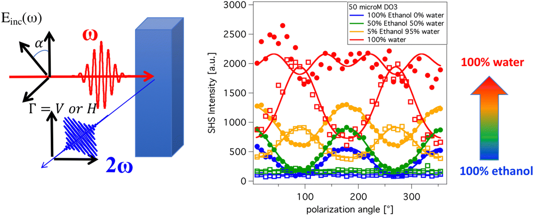
The polarization resolved SHS experimental setup is detailed elsewhere.23 The SHS intensity is monitored in the right-angle direction as a function of the input polarization angle α, see Fig. 1, which was selected with a rotating half-wave plate. The second harmonic light was selected in the Γ state using an analyzer placed in front of the spectrometer either in the vertical or in the horizontal state referred respectively as Vout and Hout states. All experimental data were recorded for 10 s under stirring conditions; a magnetic stirrer is used in the cell measurements. In all the experimental polar plots, the SHS intensity of the solvent has been removed according to the equation| |  | (1) |
where Isuspension is the intensity of the suspension, i.e. the dye in the solvent with or without imogolite, and Isolvent is the intensity of the solvent mixture alone. The experimental polarization plots are analyzed and fitted with the Fourier model:24| |  | (2) |
Here KΓSHS is a constant, IΓ2,SHS and IΓ4,SHS are the amplitudes of the second and fourth harmonics in the series, respectively. The parameter IV2,SHS is related to the local microscopic structure, i.e. the first hyperpolarizability of the emitter and IH2,SHS, IV4,SHS to the long-range correlations. In the case of uncorrelated species, the SHS signal is a purely incoherent phenomenon and these amplitudes vanish.24 In contrast, when dye orientations are correlated, the scattered photons have a well-defined phase relationship and these coefficients differ from zero.
 |
| | Fig. 1 Left: The polarization resolved SHS experimental setup. Right: The SHS polarization plots obtained with [DO3] = 0.05 mM for different ethanol–water ratio. The filled circles are I(α, Vout) polar plot and empty squares are I(α, Hout) polar plot. The solid lines are fit using the eqn (2). | |
2.3 Molecular dynamics simulations
Force fields were based on the GROMOS 54A7 parameter set.25 Topology files for DO3 and ethanol were created using the Automated Topology Builder26 and are publicly available under molecule ID 1197414 and ID 902261 respectively. The extended single point charge SPC/E water model was used. Simulations were carried out using GROMACS software27 in the NPT ensemble using a Nose–Hoover thermostat and a Parrinello–Rahman barostat. The temperature was set to 298.15 K and the pressure was maintained at 1 atmosphere. The LINear Constraint Solver (LINCS) method28 was applied to constrain all bond lengths. The time step was 2 fs, and electrostatic interactions were calculated using particle-mesh Ewald summation. Each radial distribution function (RDF) presented in Fig. 2 is calculated for 20 ns production runs using the gmx rdf function available in the GROMACS package. The RDF functions are calculated between the N–N intermolecular atom pairs as depicted in Fig. 2. A first set of MD calculation is performed on a 8 nm sized box with 6 molecules of DO3 and different ethanol–water ratios. A second calculation has been done at high dye density with 40 dyes molecules in the same 8 nm sized box filled with water solvent.
 |
| | Fig. 2 Left: The N–N radial distribution function as depicted in the scheme for different ethanol–water ratios with 6 DO3 molecules in the box. Right: The same with 40 DO3 molecules in the box. The inset shows snapshots of the structure obtained. | |
2.4 Polarization resolved SHS modelling
The computational program PySHS29,30 has been used to calculate the polarization plots of different supramolecular organizations. The inputs of this program are the hyperpolarizability of the DO3 molecule and the position and orientation of each molecule in the supramolecular aggregate. The DO3 molecule is assumed to be a 1D molecule, which means that only the hyperpolarizability component βzzz is considered. Here the z axis corresponds to the principal axis of the molecule. The position and orientation of dye in the aggregate are described for each kind of aggregate considered. All the input parameters required to perform a computation are given in the ESI.† In order to establish a direct comparison with the experimental data, the predicted polarization plots are normalized with the number of dyes in the aggregate and multiplied by the experimental I(0°, Vout) intensity of the 0.05 mM DO3 in ethanol solution. In such a way, the different predicted polarization plots can be directly compared to the experimental data.
3 Results and discussion
3.1 The DO3 behavior in a water ethanol mixture
Fig. 1 presents the evolution of the polarization resolved SHS intensity as a function of the input polarization angle α for a solution of DO3. The different colors are related to increasing the water ratio in the solvent mixture. The blue curves, obtained with ethanol as the mono solvent, exhibits the classical shape of randomly oriented molecules, well dispersed in the medium, with all the parameters IV4, IH2, IH4 close to zero. The depolarization ratio defined as the ratio of I(0°, Vout) to I(0°, Hout), is found to be 5.1 confirming the assumption that only the hyperpolarizability component βzzz has to be considered.31,32 When the water ratio increases in the mixture, the patterns of the polarization plots changes with the emergence of a peak on the Hout polar plots. This peak shows that a coherent contribution appears in the SHS Intensity. This contribution comes from correlated molecules arranged in a supramolecular aggregate.33,34 At high ethanol ratios (100 and 50%), no large aggregates are observed, while at low ethanol ratios (5% and 0%), large aggregates are present. All the coefficients of the fits are given in Table 1.
Table 1 The coefficients obtained by fit of eqn (2) on the Fig. 1 data
| Ratio |
100% ethanol |
50% ethanol |
5% ethanol |
0% ethanol |
|
I
V
2
|
0.68 |
0.69 |
0.38 |
0.04 |
|
I
V
4
|
0.01 |
0.03 |
−0.01 |
−0.07 |
|
I
H
2
|
0.00 |
−0.01 |
−0.42 |
−0.51 |
|
I
H
4
|
0.00 |
0.00 |
0.06 |
0.07 |
In order to go further and to give a microscopic description of the organization in the aggregates, molecular dynamics simulations are performed for three ethanol–water ratios: 100%, 50% and 0%. Fig. 2 left, shows the radial distribution functions obtained for these different mixtures. In the case of pure ethanol, the RDF given in the inset confirms that the dye is fully solvated and that no aggregate is observed. For a 50–50 mixture, a peak at around 0.5 nm is observed and shows the formation of dimers. In the case of pure water, this peak is always observed with oscillations showing that several molecules are packed together. In order to get structural information about the microscopic organization of the dye molecules inside the aggregate, a simulation with 40 dyes in a water box has been performed. The RDF of this simulation is presented in Fig. 2 right. The radial distribution function shows that a well-defined structure is obtained with the dye molecules packed in a layer arrangement as depicted in the snapshot taken at the end of the simulation and given in the inset, Fig. 2. This organization can be seen as a nanosheet with dye molecules distanced by 0.44 nm and oriented in a mixed “up” and “down” direction. This structure is used as a starting point to simulate the polarization plots using the PySHS package.29,30
Fig. 3 right presents the input structure used as a model for the calculation. The orientation of the dye molecules is randomly distributed between “up” and “down” with a ratio equal to 0.51. This ratio is defined by the number of “up” dye molecule orientations divided by the total number of the dye molecules in the aggregate. This ratio has been chosen to be close to 0.5 because of the results given by the molecular dynamics calculations but is not strictly equal to 0.5. Indeed, in this case, for a centrosymmetric reason, the SHS intensity would be close to zero. An additional model presented in the ESI† shows that the value of this ratio doesn’t significantly change the computed values of the coefficients IΓ2,SHS and IΓ4,SHS presented in Table 2. As is expected, it only changes the absolute SHS intensity. The simulated polarization plots presented in Fig. 3 left reproduce very nicely the experimental data presented in Fig. 1, both in absolute intensity and in the global shape. Table 2 gives the different coefficients obtained by the model and they can be directly compared to the experimentally coefficients presented in Table 1. It shows that the model of supramolecular nanosheets seems to describe correctly the spatial arrangement of the dyes in the aggregate. The evolution of those plots with the size of the aggregate also shows that increasing the water ratio in the mixture close to 100% leads to the formation of very large aggregates in the range of around 200 nm.
 |
| | Fig. 3 Simulation of the polarization resolved SHS for various 2D nanosheets with regularly spaced molecule as depicted by the scheme on the right. Blue curve is for d = 0 nm, green curve for d = 45 nm, orange for d = 150 nm and red curve for d = 190 nm. The solid lines are for the I(α, Vout) polar plots and dashed lines are I(α, Hout) polar plots. | |
Table 2 The coefficients obtained by the calculation performed by PySHS software on the 2D nanosheet organization
| Size (nm) |
0 |
45 |
150 |
190 |
|
I
V
2
|
0.67 |
0.66 |
0.49 |
0.26 |
|
I
V
4
|
0.00 |
−0.00 |
−0.04 |
−0.07 |
|
I
H
2
|
0.00 |
0.00 |
−0.26 |
−0.54 |
|
I
H
4
|
0.00 |
0.00 |
0.01 |
0.02 |
To summarize this first part, the experimental SHS results show that this technique is sensitive to the growth of aggregates which occurs upon increasing the water/ethanol ratio. We now examine the effect of IMO-CH3 addition in the aqueous dye solution.
3.2 DO3 in water with hybrid imogolite nanotubes
The dye behavior in pure water after being in contact with an IMO-CH3 nanotube suspension is considered. Fig. 4 shows the experimental polarization plot after 24 h equilibration.
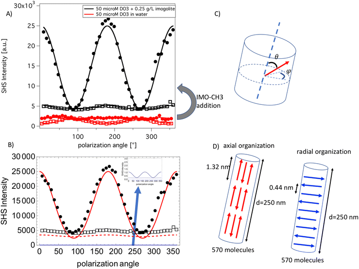 |
| | Fig. 4 (A) Black curves are the experimental polarization plots of 0.050 mM DO3 in water with 0.25 g L−1 of imogolite nanotubes (full points are Vout and empty squares are Hout plot). The red curves are obtained under the same conditions without imogolite nanotubes. The solid lines are fit according to eqn (2). (B) The red curves are the simulated polar plots obtained with an axial organization of the dye in the nanotube as depicted in the scheme (D). The blue curves are the simulated polar plots obtained with a radial organization of the dye in the nanotube as depicted in the scheme. The black points and squares are the same data as (A). (C) The definition of the angle used to describe the different organizations. (D) Description of the two models used in the computation. | |
In the presence of IMO-CH3 the polarization plots drastically change compared to the case without IMO-CH3. Both very high SHS intensity and a modified pattern of the polar plots are observed with IMO-CH3. It is known that IMO-CH3 itself does not have a significative contribution in the SHS signal, see additional data given, and therefore the change in the SHS intensity can be attributed to a confinement effect of the dye aggregate within the nanotubes. To explore this hypothesis, axial and radial dye organizations inside the nanotube are considered. In all computation, the nanotube suspension is modeled by a 250 nm long nanotube in agreement with the typically observed average length observed by atomic force microscopy,35 additional details are given in the ESI.† The axial model assumes that the dyes fill the nanotube with an angle theta, equal to 0° (“up”) or to 180° (“down”). More precisely, 570 dyes are regularly positioned along the nanotubes, as depicted in Fig. 4, with triplets of tail–head DO3 molecules forming a chain spanning the whole nanotubes. The second model assumes a radial arrangement of the dipole in the nanotubes as depicted in Fig. 4. In this case, the 570 DO3 molecules are positioned with an angle theta equal to 90° and an angle phi fixed to the same value to all molecules. The dyes are spaced by 0.44 nm, an average distance in agreement with the RDF results obtained by molecular dynamics. The polar plots obtained with the two models are presented in Fig. 4B.
The comparison between the experimental and simulated polarization plots unambiguously evidences that the axial organization is more probable. Indeed, this model reproduces the absolute intensity of the experimental data much better while the radial organization would produce a nearly zero SHS signal, as expected for this centrosymmetric arrangement. The numerical value of the IΓi,SHS coefficients obtained from the simulation are given in Table 3. In particular, the IH2 coefficient is nicely reproduced both in sign and in absolute value by the parallel model simulation.
Table 3 The coefficients obtained experimentally and by the calculation performed using PySHS software on the different filling organization
|
|
Experiment DO3 in pure water with IMO-CH3 |
Axial organization model |
Radial organization model |
|
I
V
2
|
0.72 |
0.87 |
0.61 |
|
I
V
4
|
0.01 |
0.06 |
−0.02 |
|
I
H
2
|
0.10 |
0.10 |
−0.03 |
|
I
H
4
|
0.01 |
0.00 |
0.00 |
4 Conclusions and perspectives
In pure ethanol or at low water/ethanol ratios, SHS measurements demonstrate that there is no correlation between the dyes. This means that the dyes are well dispersed and randomly distributed in solution with no assembly. In pure water or at high water/ethanol ratio, the dye is poorly soluble and SHS measurements coupled to MD simulations show that DO3 forms aggregates having a 2D nanosheet shape. In pure water those aggregates reach a very large size of about 200 nm. When IMO-CH3 are added in the dye aqueous solution, the dye molecules fill the nanotube. The SHS signal is then very different from the pure aqueous DO3 solution case, thus revealing a strong confining effect in the dye organization. The comparison of the SHS data with a radial and axial model enables unambiguously evidencing that the dyes are organized with their axis parallel to the nanotube walls. To our knowledge, it is the first time that polarization resolved SHS technique demonstrates its ability to probe molecular organization inside a nanotube. The different models and organizations proposed in this work reproduce nicely, without any adjustable parameters, the experimental data in all the different conditions: dye alone is well solubilized in ethanol, dye aggregate in water–ethanol mixture and dye filling the nanotube. The models and the related numerical code developed here are quite general and open new perspectives to probe confined organization inside IMO-CH3 nanotubes. The extension to different tube loading and the correlation with the confined chemical reactions would be very interesting and will be the subject of future experiments.
Conflicts of interest
There are no conflicts to declare.
Acknowledgements
The authors thank the ANR BENALOR for funding (ANR-20-CE09-0029). The authors thank also Pierre Picot for fruitful discussions about hybrid imogolite materials.
References
- N. T. Southall, K. A. Dill and A. D. J. Haymet, J. Phys. Chem. B, 2002, 106, 521–533 CrossRef CAS.
-
C. Tanford, The hydrophobic effect: formation of micelles and biological membranes, J. Wiley, 2nd edn, 1980 Search PubMed.
-
A. Y. Ben-Naim, Hydrophobic interactions, Springer Science & Business Media, 2012 Search PubMed.
- K. Patil, R. Pawar and P. Talap, Phys. Chem. Chem. Phys., 2000, 2, 4313–4317 RSC.
- P. Bauduin, A. Renoncourt, A. Kopf, D. Touraud and W. Kunz, Langmuir, 2005, 21, 6769–6775 CrossRef CAS PubMed.
- N. F. A. van der Vegt and D. Nayar, J. Phys. Chem. B, 2017, 121, 9986–9998 CrossRef CAS PubMed.
- J. Gregory, Polym. Int., 1994, 35, 105–106 CrossRef.
- I. Bottero, B. Bonelli, S. E. Ashbrook, P. A. Wright, W. Zhou, M. Tagliabue, M. Armandi and E. Garrone, Phys. Chem. Chem. Phys., 2011, 13, 744–750 RSC.
- M. S. Amara, E. Paineau, S. Rouzière, B. Guiose, M.-E. M. Krapf, O. Taché, P. Launois and A. Thill, Chem. Mater., 2015, 27, 1488–1494 CrossRef CAS.
- P. Picot, F. Gobeaux, T. Coradin and A. Thill, Appl. Clay Sci., 2019, 178, 105133 CrossRef CAS.
- S. Patra, D. Schaming, P. Picot, M.-C. Pignié, J.-B. Brubach, L. Sicard, S. Le Caër and A. Thill, Environ. Sci.: Nano, 2021, 8, 2523–2541 RSC.
- G. Martin-Gassin, E. Paineau, P. Launois and P.-M. Gassin, J. Phys. Chem. Lett., 2022, 13, 6883–6888 CrossRef CAS PubMed.
- Y. Chen, H. I. Okur, N. Gomopoulos, C. Macias-Romero, P. S. Cremer, P. B. Petersen, G. Tocci, D. M. Wilkins, C. Liang, M. Ceriotti and S. Roke, Sci. Adv., 2016, 2, e1501891 CrossRef PubMed.
- G. Revillod, J. Duboisset, I. Russier-Antoine, E. Benichou, G. Bachelier, C. Jonin and P.-F. Brevet, J. Phys. Chem. C, 2008, 112, 2716–2723 CrossRef CAS.
- M. Moris, M.-P. Van Den Eede, G. Koeckelberghs, O. Deschaume, C. Bartic, S. Van Cleuvenbergen, K. Clays and T. Verbiest, Commun. Chem., 2019, 2, 130 CrossRef CAS.
- S. Van Cleuvenbergen, Z. J. Smith, O. Deschaume, C. Bartic, S. Wachsmann-Hogiu, T. Verbiest and M. A. van der Veen, Nat. Commun., 2018, 9, 3418 CrossRef PubMed.
- G. Gonella and H.-L. Dai, Langmuir, 2014, 30, 2588–2599 CrossRef CAS PubMed.
- M. Bischoff, N. Y. Kim, J. B. Joo and A. Marchioro, J. Phys. Chem. Lett., 2022, 13, 8677–8683 CrossRef CAS PubMed.
- W. M. K. P. Wijekoon, Y. Zhang, S. P. Karna, P. N. Prasad, A. C. Griffin and A. M. Bhatti, J. Opt. Soc. Am. B, 1992, 9, 1832–1842 CrossRef CAS.
- B. Derkowska-Zielinska, K. Fedus, H. Wang, C. Cassagne and G. Boudebs, Opt. Mater., 2017, 72, 545–548 CrossRef CAS.
- M. Boyer, E. Paineau, M. Bacia-Verloop and A. Thill, Appl. Clay Sci., 2014, 96, 45–49 CrossRef CAS.
- P. Picot, Y. Liao, E. Barruet, F. Gobeaux, T. Coradin and A. Thill, Langmuir, 2018, 34, 13225–13234 CrossRef CAS PubMed.
- P.-M. Gassin, S. Bellini, J. Zajac and G. Martin-Gassin, J. Phys. Chem. C, 2017, 121, 14566–14571 CrossRef CAS.
- J. Duboisset and P.-F. Brevet, Phys. Rev. Lett., 2018, 120, 263001 CrossRef CAS PubMed.
- N. Schmid, A. P. Eichenberger, A. Choutko, S. Riniker, M. Winger, A. E. Mark and W. F. van Gunsteren, Eur. Biophys. J., 2011, 40, 843–856 CrossRef CAS PubMed.
- A. K. Malde, L. Zuo, M. Breeze, M. Stroet, D. Poger, P. C. Nair, C. Oostenbrink and A. E. Mark, J. Chem. Theory Comput., 2011, 7, 4026–4037 CrossRef CAS PubMed.
- H. J. C. Berendsen, D. van der Spoel and R. van Drunen, Comput. Phys. Commun., 1995, 91, 43–56 CrossRef CAS.
- B. Hess, H. Bekker, H. J. C. Berendsen and J. G. E. M. Fraaije, J. Comput. Chem., 1997, 18, 1463–1472 CrossRef CAS.
- L. Boudjema, H. Aarrass, M. Assaf, M. Morille, G. Martin-Gassin and P.-M. Gassin, J. Chem. Inf. Model., 2020, 60, 5912–5917 CrossRef CAS PubMed.
- L. Boudjema, H. Aarrass, M. Assaf, M. Morille, G. Martin-Gassin and P.-M. Gassin, J. Chem. Inf. Model., 2021, 61, 5719 CrossRef CAS PubMed.
- P. Kaatz and D. P. Shelton, J. Chem. Phys., 1996, 105, 3918–3929 CrossRef CAS.
- R. Bersohn, Y. H. Pao and H. L. Frisch, J. Chem. Phys., 1966, 45, 3184–3198 CrossRef CAS.
- J. Duboisset, F. Rondepierre and P.-F. Brevet, J. Phys. Chem. Lett., 2020, 11, 9869–9875 CrossRef CAS PubMed.
- P.-M. Gassin, B. Prelot, B. Grégoire and G. Martin-Gassin, Langmuir, 2018, 34, 12206–12213 CrossRef CAS PubMed.
- P. Picot, O. Taché, F. Malloggi, T. Coradin and A. Thill, Faraday Discuss., 2016, 191, 391–406 RSC.
|
| This journal is © the Owner Societies 2023 |
Click here to see how this site uses Cookies. View our privacy policy here. 
 Open Access Article
 This Open Access Article is licensed under a Creative Commons Attribution-Non Commercial 3.0 Unported Licence
 b,
Benedicte
Prelot
a,
Gaelle
Martin-Gassin
a and
Pierre-Marie
Gassin
b,
Benedicte
Prelot
a,
Gaelle
Martin-Gassin
a and
Pierre-Marie
Gassin