
 Open Access Article
 This Open Access Article is licensed under a
 Creative Commons Attribution 3.0 Unported Licence
Radicals in aqueous solution: assessment of density-corrected SCAN functional†
Fabian
Belleflamme
 and
Jürg
Hutter
*
and
Jürg
Hutter
*
Department of Chemistry, University of Zurich, Zurich, Switzerland. E-mail: hutter@chem.uzh.ch
First published on 17th July 2023
Abstract
We study self-interaction effects in solvated and strongly-correlated cationic molecular clusters, with a focus on the solvated hydroxyl radical. To address the self-interaction issue, we apply the DC-r2SCAN method, with the auxiliary density matrix approach. Validating our method through simulations of bulk liquid water, we demonstrate that DC-r2SCAN maintains the structural accuracy of r2SCAN while effectively addressing spin density localization issues. Extending our analysis to solvated cationic molecular clusters, we find that the hemibonded motif in the [CH3S∴CH3SH]+ cluster is disrupted in the DC-r2SCAN simulation, in contrast to r2SCAN that preserves the (three-electron-two-center)-bonded motif. Similarly, for the [SH∴SH2]+ cluster, r2SCAN restores the hemibonded motif through spin leakage, while DC-r2SCAN predicts a weaker hemibond formation influenced by solvent–solute interactions. Our findings demonstrate the potential of DC-r2SCAN combined with the auxiliary density matrix method to improve electronic structure calculations, providing insights into the properties of solvated cationic molecular clusters. This work contributes to the advancement of self-interaction corrected electronic structure theory and offers a computational framework for modeling condensed phase systems with intricate correlation effects.
1. Introduction
Density-corrected density functional theory (DC-DFT) has a rich history dating back to the early days of practical DFT simulations. Initially, researchers sought to enhance the Hartree–Fock (HF) density with density functionals containing correlation effects in a non-self-consistent manner.1,2 However, the rapid advancements in Kohn–Sham DFT (KS-DFT) and advanced exchange–correlation functionals have made these approaches less relevant, as Kohn–Sham densities often provide excellent approximations to the exact density.3 Moreover, self-consistent densities enable straightforward access to various molecular properties of interest, such as forces and stress tensors, crucial for molecular dynamics simulations.The core concept behind DC-DFT4,5 is the separation of the total energetic error in Kohn–Sham DFT calculations into functional-driven and density-driven components. Based on this rigorously defined framework, the field of DC-DFT has undergone a renaissance in recent years.6–12 In contrast to the initial interest in density-corrected methods, current attention has shifted towards the limitations of exchange–correlation functionals based on the generalized gradient approximation (GGA), which can lead to density-driven errors and enhanced electron density delocalization.13,14 In such cases, the self-interaction-free Hartree–Fock density has emerged as a viable surrogate for the exact density. When combined with a Kohn–Sham energy functional employing the strongly-constrained and appropriately normed SCAN functional,15 this approach, referred to as DC-SCAN,8,9 yields exceptional results, demonstrating chemical accuracy in the study of water clusters.
The SCAN functional,15 known for satisfying all 17 exact constraints for meta-GGA functionals, has garnered significant interest in the field. It has demonstrated superior performance compared to other functionals in aqueous systems.16 However, like many other functionals, SCAN is susceptible to density-driven errors, which can result in the artificial over-stabilization of hydrogen-bonded systems.3,9 To address numerical stability and grid convergence issues of the original functional, we used the regularized-restored r2SCAN17 in this study.
In certain cases, the utilization of the Hartree–Fock density instead of the self-consistently obtained Kohn–Sham density has shown promise in mitigating density-driven errors.6,7,11 The application of DC-DFT,5 when appropriately employed, has demonstrated improved simulation accuracy, particularly when density-driven errors overshadow functional-driven errors. Notably, DC-SCAN has shown favorable performance, even surpassing the sophisticated deep-learned local-hybrid functional DM21 developed by DeepMind.10
The research by Dasgupta et al.8,9 has repeatedly demonstrated that the addition of dispersion corrections, such as D3,18 negatively impacts the energetics of SCAN and DC-SCAN in both charged and neutral water clusters. Based on these finding, we chose not to incorporate dispersion corrections in our study. Although, Song et al.12 recently emphasized the importance of adding a reparametrized D4 dispersion correction19 to HF-r2SCAN, for accurately describing long-range dispersion interactions.
The usability of density-corrected DFT methods is constrained by two primary issues. Firstly, the evaluation of the DC-DFT energy functional relies on a density, typically the Hartree–Fock density, which was variationally optimized for a different energy functional. This non-variational nature of the DC-DFT energy functional with respect to the reference density poses limits on its applicability. This becomes evident in the challenges associated with accessing forces and performing geometry optimizations, which are not trivial tasks.20 Secondly, the computation of the reference density through Hartree–Fock calculations poses a significant bottleneck. Unlike KS-DFT, which exhibits cubic scaling ![[scr O, script letter O]](https://www.rsc.org/images/entities/char_e52e.gif) (N3) with system size N, obtaining the Hartree–Fock exchange involves solving the computationally demanding, formally quartic scaling (N4) four-center two-electron repulsion integrals.
(N3) with system size N, obtaining the Hartree–Fock exchange involves solving the computationally demanding, formally quartic scaling (N4) four-center two-electron repulsion integrals.
Overcoming the challenge of accessing self-consistent analytical nuclear gradients in DC-SCAN has in the past been addressed through the development of data-driven potential energy functions within a many-body formalism.8 While the theoretical framework for a variational formulation of DC-DFT has been proposed for some time,21 its widespread implementation in quantum chemistry codes is still limited.22 However, the availability of analytical forces in DC-DFT would offer significant advantages, as it not only addresses the challenge of self-consistency but also improves standard DFT forces and geometries in density-sensitive calculations. The wider adoption of such implementations would enable comprehensive investigations into the performance of DC-DFT in terms of both geometries and energies.20
Here, we present a variational formulation of density-corrected DFT, implemented in the CP2K software package.23,24 The implementation follows the framework proposed by Verma et al.,21 and which extends the recently developed variational Harris functional energy correction.25 Our approach utilizes the auxiliary density matrix method (ADMM)26 and truncated interaction potentials,27 available in CP2K, for efficient computation of the Hartree–Fock density. Effectively, the DC-DFT method employed here should be named ADMM-DC-r2SCAN, but for sake of readability the ADMM label will be omitted henceforth.
We aim to explore the potential of this advanced DFT method in addressing self-interaction errors that arise in strongly-correlated materials. Specifically, we focus on the aqueous hydroxyl radical as a challenging system to simulate accurately using conventional exchange–correlation functionals. In DFT simulations, a two-center, three-electron (2c-3e) hemibond is observed in the first solvation shell of the hydroxyl radical due to favorable overlap between the singly-occupied molecular orbital of the radical and the Frontier lone pair of a neighboring water molecule. However, this hemibond disappears when the same structures are relaxed at the MP2 level, leaving behind a “pseudo hemibond” with a close contact between oxygen atoms.28
Previous investigations into the hemibonded motif in theoretical studies have attributed its origin to factors such as self-interaction errors in GGA-based DFT,29,30 size effects,31 or even an intricate interplay between these factors.28,32 In line with these studies, our investigation aims to contribute to the understanding of the hemibonded motif by offering a new perspective to this extensively researched and complex puzzle.
In addition to revisiting lingering questions regarding the prevalence of the hydroxyl–water hemibond in theoretical studies, we also investigate the radical cation clusters [CH3S∴CH3SH]+33 and [HS∴SH2]+.34–36 The sulfur–sulfur hemibonded configuration in these clusters has been predicted to be more stable than the hydrogen-bonded motif in the gas phase. It has been suggested that the hemibonded ion core in these clusters remains stable upon microhydration with a single water molecule, while the (2c-3e) bond breaks upon proton transfer in the presence of a single methanol or ethanol molecule.37,38 Here, we expand on these findings by investigating the behavior of these systems in a fully solvated environment, aiming to determine how the stability of the hemibonded motif is influenced by the solvent.
The article is structured as follows: Section 2 covers the development and implementation of the DC-r2SCAN method. Section 3 provides details regarding the computational setup for the MD simulations. Section 4 validates the DC-r2SCAN implementation by comparing its performance in reproducing the structure of bulk liquid water. Section 5 investigates hemibonding in solvated radicals and radical cation clusters. Finally, Section 6 presents the conclusion and outlines future research possibilities.
2. Method development
2.1 The density-corrected energy functional
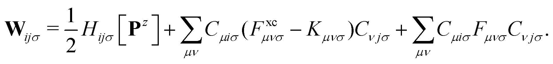
The density corrected DFT energy functional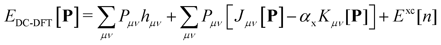 | (1) |
The scaling factor αx assumes a value of 1 in the context of Hartree–Fock theory. In the case of Kohn–Sham theory, this factor is set to zero unless a hybrid functional is employed, requiring an additional contribution from the exchange–correlation potential Fxc.
The density matrix P is defined as a function of the occupied molecular orbital (MO) coefficients C and is expanded in the atomic orbital (AO) basis. This expansion is expressed by the equation:
 | (2) |
2.2 The variational DC-DFT Lagrangian
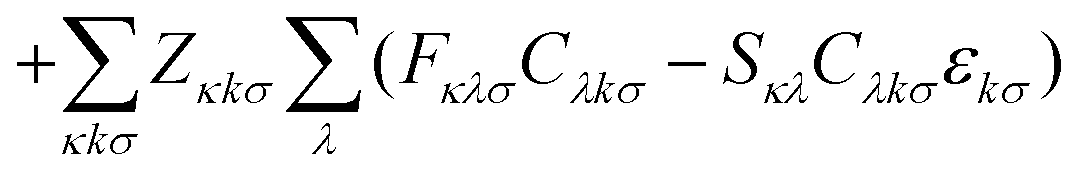
Nuclear gradients and the stress tensor are indispensable to compute molecular properties. To avoid the computational expense associated with determining the first-order response of the MO coefficients, which takes into account the geometry dependence of the AOs, the DC-DFT energy functional can be extended by means of two additional constraints. This extension leads to the formulation of the DC-DFT Lagrangian, which can be expressed as:![[script L]](https://www.rsc.org/images/entities/char_e144.gif) DC-DFT[C, W, Z] = EDC-DFT[P] DC-DFT[C, W, Z] = EDC-DFT[P] | (3a) |
 | (3b) |
 | (3c) |
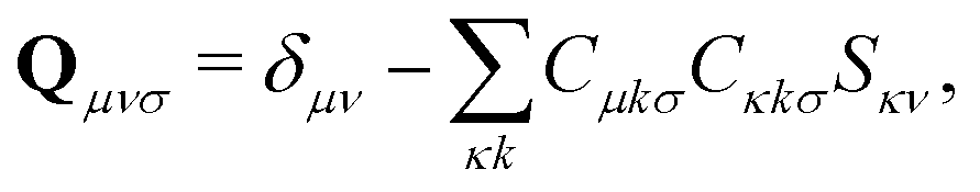
The first additional constraint, (eqn (3b)), ensures the stationarity of the ground-state equations, whether they are based on Kohn–Sham or Hartree–Fock theory. By rearranging the equations and utilizing the definition of the projection operator Q
 | (4) |
 | (5) |
 | (6) |
Only the virtual-occupied blocks of the Z vector, denoted as Z, contribute, while the occupied–occupied block is implicitly assumed to be zero:
 | (7) |
The Fock/Kohn–Sham operator F[P] appearing in the Brillouin constraint is defined as:
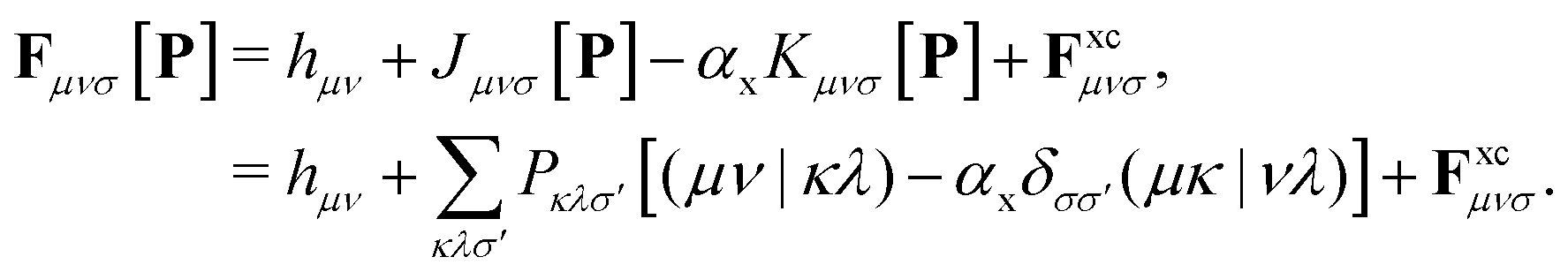 | (8) |
In the case of DC-r2SCAN, F simplifies to the Fock operator, with αx = 1 and without the exchange–correlation potential Fxc. Efficient treatment of the exact Hartree–Fock exchange (HFX) in the reference and linear response equations is achieved through the ADMM approximation in CP2K.
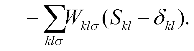
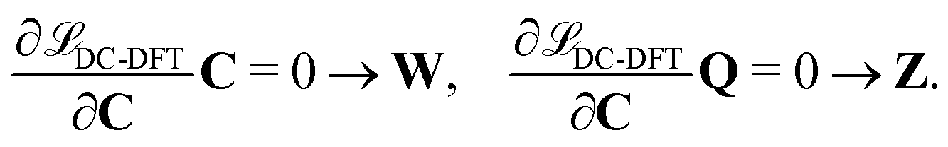
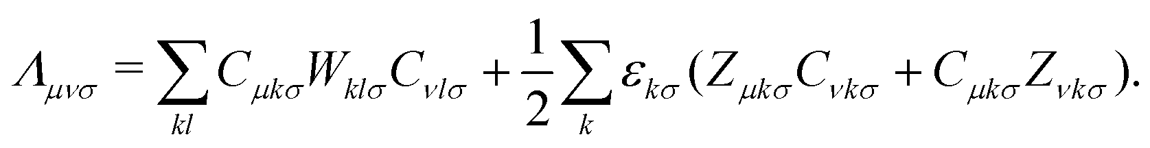
The second additional constraint ensures the orthogonality of the occupied MOs. Analogous to Z, this constraint is assumed to be symmetric. The determination of the Lagrange multipliers W and Z involves taking the derivative of DC-DFT with respect to the MO coefficients C and projecting onto either the virtual or occupied space:
 | (9) |
 | (10) |
The matrix W exclusively includes occupied–occupied contributions. The intermediate H is derived from the KS matrix contributions of the kernel matrix and varies depending on the chosen reference functional:
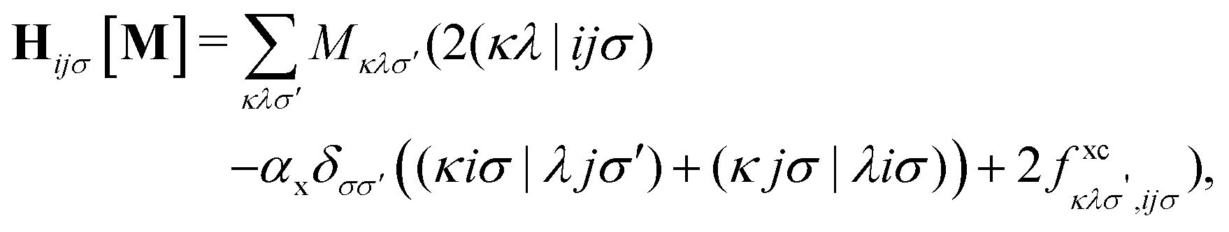 | (11) |
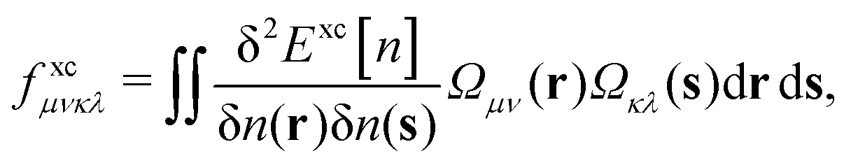 | (12) |
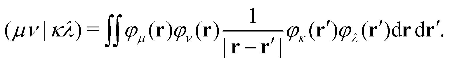 | (13) |
The linear Z-vector equation, derived from eqn (9), can be expressed as:
| AZ = −B, | (14) |
 | (15) |
The terms on the left-hand side of eqn (15) originate from the chosen ground-state energy functional and are independent of the density correction on the right-hand side. The right-hand side B represents the difference between the DC-DFT and the reference energy functional. Specifically, in the case of DC-r2SCAN, it reduces to the difference between the XC-potential of the r2SCAN functional and the exact exchange contribution to the Fock operator of the reference calculation:
 | (16) |
The response density matrix Pz is defined as:
 | (17) |
The response equations (eqn (15) are solved iteratively using the conjugate gradient method.39 A trial solution X is constructed and updated until the matrix-vector product  converges to the right-hand-side property gradient B. The orbital Hessian consists of a Coulomb and exchange part, both of which must be consistently updated with the calculation of Fock matrix contributions during the SCF procedure.
2.3 Auxiliary density matrix method
The addition of non-local Hartree–Fock exchange (HFX) to density-corrected DFT methods introduces a significant computational burden. The computational cost of HFX scales with the fourth power of the system size due to the evaluation of 4-electron 2-center electron repulsion integrals (ERIs) required to obtain the Hartree–Fock exchange energy. The HFX energy is given by: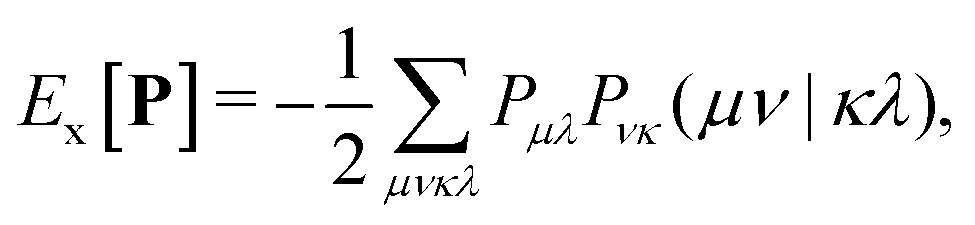 | (18) |
Although techniques such as integral screening40 and the utilization of short-range exchange operators41,42 have partially addressed this issue, the scaling with respect to basis set quality remains poor in periodic systems. To overcome this challenge, the auxiliary density matrix method (ADMM)26,27 was developed and implemented in the CP2K software package.
The ADMM approach accelerates the evaluation of HFX by introducing an auxiliary density matrix ![[P with combining circumflex]](https://www.rsc.org/images/entities/b_char_0050_0302.gif) that is either smaller in size or decays more rapidly than the original density matrix. The HFX energy is then approximated using the following expression:
that is either smaller in size or decays more rapidly than the original density matrix. The HFX energy is then approximated using the following expression:
| Ex = EHFXx[] + (EHFXx[P] − EHFXx[]) | (19) |
| ≈EHFXx[] + (EDFTx[P] − EDFTx[]) | (20) |
By introducing a smaller and/or less diffuse auxiliary basis, ADMM provides an efficient approximation for computing HFX integrals. The method assumes that the basis set incompleteness error in the exchange energy between the primary and auxiliary density matrices can be well captured by a GGA, even in the presence of qualitative differences between GGA exchange and HFX. By introducing a GGA functional in ADMM, the method is no longer self-interaction-free, unlike the exact exchange that is approximated. Nevertheless, ADMM has been shown to maintain intermediate degrees of localization, depending on the employed exchange fraction.26
Among the many variants of the ADMM method,26,43,44 two commonly studied approaches are purified wave function fitting (ADMM1) and non-purified wave function fitting (ADMM2). In ADMM2, the auxiliary MO coefficients minimize the square difference between occupied wave functions in the primary and auxiliary bases, while the auxiliary density matrix is obtained through a simple projection. Purified wave function fitting, in addition to this, enforces orthonormality, ensuring that the auxiliary density matrix satisfies the idempotency conditions.45 Consequently, an eigenvalue correction step is necessary with purified wave function fitting before using the resulting Kohn–Sham matrix for DC-DFT.
In the following discussion, we focus on ADMM2, which does not require any post-SCF treatment. The ADMM2-approximated results will be referred to using the general acronym ADMM. The speedup achieved in the evaluation of the Hartree–Fock exchange with the ADMM method depends on the choice of primary and auxiliary basis sets and can often reach orders of magnitude. The ADMM method has been employed before in the context of linear response and time-dependent density functional theory (TDDFT), where the linear response equations have been extended to include the ADMM terms.46,47
2.4 Nuclear gradients
Finally, let us consider the gradient of the DC-DFT Lagrangian with respect to the nuclear coordinate R. The expression for the nuclear gradient is given by: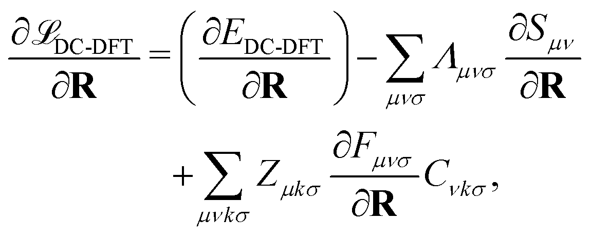 | (21) |
 | (22) |
These equations provide a means to compute the gradient of the energy with respect to the nuclear coordinates. Analogous equations can be derived to obtain the gradient with respect to the strain tensor, which allows for the calculation of the stress tensor.
3. Computational details
All simulations were performed using the QUICKSTEP module in the CP2K simulation software package,23,24 in the Gaussian and plane waves (GPW) framework48 with 3D periodic boundary conditions. The atomic core electrons were described using Goedecker–Teter–Hutter (GTH) pseudopotentials,49,50 while the valence electron molecular orbitals were expanded in triple-ζ double-polarized basis sets (TZV2P),51 which were optimized with the numerical ATOM code of CP2K for the SCAN functional. The kinetic energy cutoff for the plane-wave expansion of the density was set to 1200 Ry.52To mitigate the computational cost associated with the quartic scaling ((N4)) of the four-center two-electron integrals, the exchange calculations of the DC-SCAN simulations employed ADMM.26 A contracted and polarized auxiliary basis set consisting of three Gaussian exponents for each valence orbital (cpFIT3) was used to construct the smaller and rapidly decaying auxiliary density matrix. The PBE exchange functional was employed to correct the basis set incompleteness error introduced by the auxiliary basis. The truncated Coulomb operator27 had a cutoff radius of 6.0 Å, approximately half the length of the smallest edge of the simulation cell for all systems. The Schwarz integral screening threshold was set to 10−6 atomic units.
The Born–Oppenheimer ab initio molecular dynamics simulations were performed in the canonical (NVT) ensemble with the CSVR thermostat53 at a temperature of 350 K and a time step of 0.5 fs. The solvated radical and cluster systems were generated using Packmol.54 The systems were initially equilibrated through a 1 ps MD simulation with a thermostat attached to each degree of freedom and a time constant of 10 fs, followed by 2.5 ps of equilibration with a single thermostat controlling all degrees of freedom and a time constant of 100 fs. The production runs were conducted for a duration of 30 ps. Evolution of the conserved energy and temperature fluctuations are listed in the ESI.†
The radial distribution functions were calculated using VMD55 over the entire 30 ps trajectory of the production runs, with a bin width of 0.01 Å. Hydrogen bond analysis was performed using MDanalysis.56
4. Validation
In order to validate our implementation, we first examined a system consisting of 64 water molecules. The objective was to compare the simulated structure with those of bulk liquid water under ambient conditions, specifically at a temperature of 300 K and volumetric mass density of 1 g cm−3. To achieve the desired volumetric mass density, we arranged the molecules within a cubic simulation cell, with a side-length of 12.4138 Å.4.1 Structural properties of bulk liquid water
The radial distribution functions of bulk liquid water (H2O)64 are presented in Fig. 1. We found that r2SCAN and DC-r2SCAN accurately reproduce the structure of bulk liquid water at ambient temperatures,57 specifically at 350 K. This temperature was carefully selected to avoid freezing and ensure a high level of agreement between the theoretical RDFs and experimental data. Previous simulations using the SCAN functional at 300 K exhibited excessive structuring compared to experimental observations,52 while at 330 K, SCAN resulted in an augmented first solvation shell.58,59 Notably, a recent study employing a machine-learned KS-SCAN potential predicted the freezing temperature of water to be 312.5 K.60 In this work we do not consider the explicit treatment of nuclear quantum effects (NQEs). It has been debated in the past, that elevated temperatures may also account for NQEs,59,61,62 which aligns with our cautious approach to prevent freezing. The necessity of incorporating NQEs into the analysis remains a topic of ongoing discussion.63,64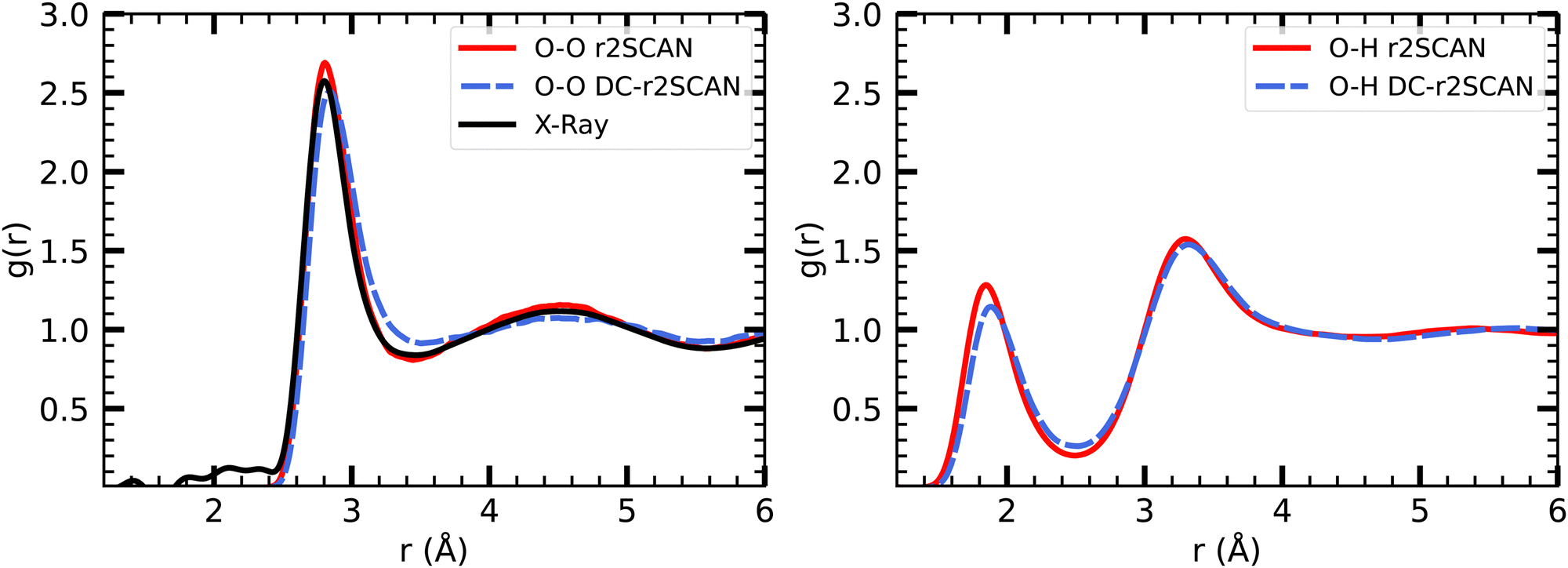 | ||
| Fig. 1 RDFs for (left panel) O–O, and (right panel) O–H with (solid red) r2SCAN and (dashed blue) DC-r2SCAN, for bulk liquid water. Experimental XRD data (solid black).57 | ||
Our results confirm the suitability of 350 K as an appropriate temperature for DFT simulations of bulk liquid water using the r2SCAN and DC-r2SCAN functionals, offering an accurate description of the water structure that aligns with experimental measurements.
In Table 1, we report the positions and intensities of the first maximum, first minimum and coordination number between the oxygen atoms, and compare them with the experimental values for pure liquid water at ambient conditions. The peak positions and intensities, obtained for both r2SCAN and DC-r2SCAN, align well with the experimental values. The coordination number nOO in Table 1 is defined57 as
 | (23) |
| r2SCAN | DC-r2SCAN | Experimental57 | |
|---|---|---|---|
| r 1 (Å) | 2.865 | 2.845 | 2.801 |
| g 1 | 2.312 | 2.508 | 2.575 |
| r 2 (Å) | 3.505 | 3.505 | 3.454 |
| g 2 | 0.824 | 0.913 | 0.842 |
| n OO | 4.321 | 4.370 | 4.310 |
5. Results and discussion
5.1 Solvated hydroxyl radical
Density functional theory commonly relies on GGA functionals, which strike a favorable balance between computational cost and accuracy, making them suitable for large-scale molecular dynamics simulations.29 However, certain systems, such as the solvated hydroxyl radical, display exceptional behavior that challenges conventional GGA simulations. In particular, a distinctive bonding arrangement known as a two-center three-electron hemibond between the hydroxyl radical and the solvent has been observed and extensively discussed over the past two decades. The origin of this hemibonded structure has been the subject of ongoing research efforts. Recently, Rana and Herbert32 provided a comprehensive summary of these investigations. In this study, we reexamine the solvated hydroxyl radical using the DC-r2SCAN functional and compare our results to those obtained from the r2SCAN functional, aiming to contribute new insights to this complex phenomenon.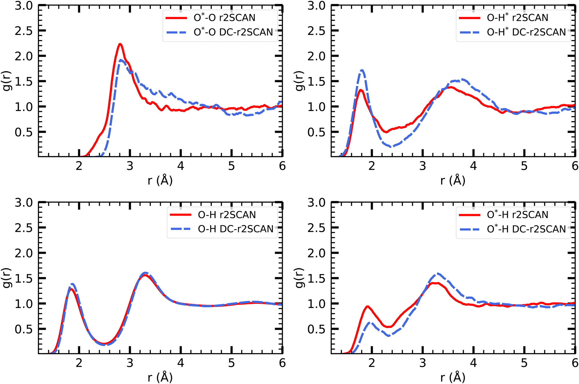 | ||
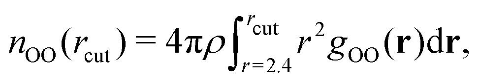
| Fig. 2 RDFs of O*–O (upper left), O–H* (upper right), O–H (lower left) and O*–H (lower right) for r2SCAN (solid red) and DC-r2SCAN (dashed blue). O (O*) and H (H*) denote the water (hydroxyl) atoms. | ||
The various O–H pair correlation functions in Fig. 2, reveal a first insight on the hydrogen bonding network. The average hydrogen bond length for r2SCAN and DC-r2SCAN, respectively, are 1.79 Å and 1.82 Å where ˙OH acts as donor (O–H*), 1.93 Å and 2.04 Å where ˙OH acts as acceptor (O*–H), and 1.85 Å and 1.87 Å between solvent molecules (O–H).
We find for both methods that the hydrogen bond is shorter when the hydroxyl acts as donor. Considering the overall difference in peak height, there is a higher probability of finding a donor rather than an acceptor bond. In particular, the DC-r2SCAN donor peak is higher than that for r2SCAN, indicating a higher probability of occurrence and increased strength of the donor hydrogen bond in DC-r2SCAN. This difference in donor peak height then also predicts a less stable donor hydrogen bond with the r2SCAN functional. Integrating the first donor hydrogen bond peak yields 0.96 for r2SCAN and 1.00 for DC-r2SCAN. The radical can donate only one hydrogen bond, so the donor bond exists always in DC-r2SCAN.
On the other hand, the r2SCAN acceptor (O*–H) peak is higher than the peak observed for DC-r2SCAN, suggesting a higher probability of acceptor bond occurrence. This might be due to the enhanced delocalization of the electron density predicted by the r2SCAN functional, leading to more acceptor hydrogen bonds. This can be seen by integrating the first solvation shell, which yields a value of 1.4 for r2SCAN and 0.99 for DC-r2SCAN.
In Table 2, we report the positions and intensities of the first maximum, first minimum and coordination number between the radical and solvent oxygen atoms, and compare them with the experimental values for pure liquid water at ambient conditions. The lower g1 peak in DC-r2SCAN in comparison to r2SCAN is likely linked to the much more diffuse first solvation shell, as can be seen from the far location of the first minimum at 4.985 Å. In comparable hybrid functional studies of systems with 64 molecules the first minimum is located in the range of 3.2 Å to 3.7 Å,28,32 and at 4.4 Å with the revAPBEK functional.65
| r2SCAN | DC-r2SCAN | |
|---|---|---|
| r 1 (Å) | 2.805 | 2.815 |
| g 1 | 2.233 | 1.917 |
| r 2 (Å) | 4.065 | 4.985 |
| g 2 | 0.910 | 0.828 |
| n OO | 4.542 | 4.145 |
In Fig. 3, we show the distribution of the number of hydrogen bonds between the solvent and the hydroxyl radical. In r2SCAN calculations, the number of hydrogen bonds between the solvent and radical is on average three. The likelihood of three hydrogen bonds on the hydroxyl radical is reduced by 25.8% in DC-r2SCAN, in comparison to r2SCAN. Conversely, configurations with two hydrogen bonds are 25% more likely with DC-r2SCAN, compared to r2SCAN. DC-r2SCAN reproduces the trend of self-interaction corrected BLYP simulations.29 Furthermore, in cases where three hydrogen bonds are formed between the radical and the solvent, the radical acts twice as acceptor and once as donor, confirming the results reported by VandeVondele et al.29
 | ||
| Fig. 3 Distribution of the number of hydrogen bonds between solvent and the ˙OH˙ radical for r2SCAN (red circles), DC-r2SCAN (blue diamonds), and self-interaction corrected BLYP29 (black squares). | ||
The hydrogen bonding between the solvent molecules in the system was analyzed, excluding the hydroxyl radical. The average number of hydrogen bonds per water molecule is 3.59 ± 0.11 and 3.65 ± 0.11 for r2SCAN and DC-r2SCAN, respectively. These values are in agreement with the inferred experimental value of 3.5867 and previous hybrid functional results.68 Notably, the higher average number of hydrogen bonds in DC-r2SCAN indicates that the solvent is more strongly bound to itself compared to r2SCAN. This observation is consistent with the lower average number of hydrogen bonds between the radical and the solvent in DC-r2SCAN compared to r2SCAN, as shown in Fig. 3.
It needs to be stressed that the hydrogen bond analysis strongly depends on the criteria that are chosen to define a hydrogen bonding event. Since it is not an observable in liquid water experiments that can be measured or calculated, definitions of hydrogen bonding are manifold.69,70 In particular, within the simple geometric criterion we apply here, adjusting the cutoff criteria has drastic effects on the hydrogen bond analysis. Tightening the criterion on the hydrogen bond angle from 135° to 150° reduces the average number of hydrogen bonds per water molecule to 2.83 ± 0.17 and 2.981 ± 0.16 for r2SCAN and DC-r2SCAN, respectively.
The hydrogen bonding network in liquid water DFT simulations is strongly affected, not only by the extensive liberty of choosing the hydrogen bonding parameters, but also by dispersion correction methods such as the D3 correction by Grimme,18 which can significantly enhance the hydrogen bonding network. However, the use of the D3 method in its original parametrization, has been shown to introduce significant overbinding, leading to an overall deterioration of the energetics for SCAN and DC-SCAN.8,9 Therefore, these corrections were omitted in our study.
In a recent study by Song et al.,12 it has been argued that despite delivering high accuracy for pure water simulations, DC-r2SCAN without a dispersion correction cannot accurately describe long-range dispersion interactions in other non-covalent systems. Therefore, the use of dispersion corrections may still be necessary to accurately describe non-covalent interactions of different nature, and a reparametrized D4 dispersion correction19 was required to achieve this accuracy in standard non-covalent datasets.
In Fig. 4 we plot the distribution of hydrogen bond angles between the radical and the solvent when the distance criterion is satisfied, considering the radical as either a donor (upper panels) or an acceptor (lower panels). For both r2SCAN and DC-r2SCAN, the distributions of donor hydrogen bonds exhibit a prominent peak centered around 165°. In particular with the latter method, a well-defined peak in the donor hydrogen bond distribution can be identified. Together with the previously mentioned increase in hydrogen bonds involving the radical as a donor (see Fig. 2), this signifies a preferential structuring of the solute-solvent system in DC-r2SCAN functional simulations.
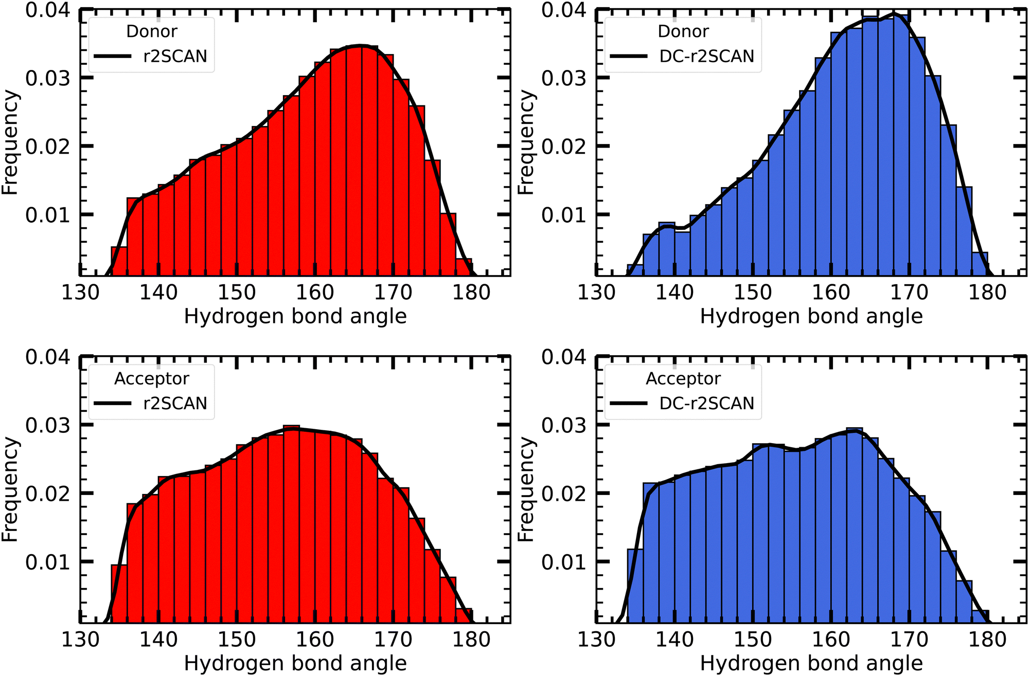 | ||
| Fig. 4 Distribution of the hydrogen bond angles between solvent and the ˙OH˙ radical, where the radical acts as donor (upper panels), and acceptor (lower panels). | ||
Furthermore, the observed slower decrease in the radial distribution function (RDF) and the extended first solvation shell in DC-r2SCAN simulations suggest the presence of hydrophobic effects. This implies that water molecules exhibit a more ordered structure around the hydroxyl radical, leading to a slower decay in the RDF and an enhanced solvation shell, as shown by the prominent peaks in the hydrogen bond angle distribution, compared to r2SCAN simulations.
Conversely, the distribution of hydrogen bond angles where the radical acts as acceptor is much more uniform. Although the r2SCAN functional simulations showed a preference for the radical to act as a hydrogen bond acceptor, no specific orientation can be identified. Consequently, the more flexible and weaker acceptor hydrogen bonds do not contribute to a more structured and enhanced hydrogen bonding network.
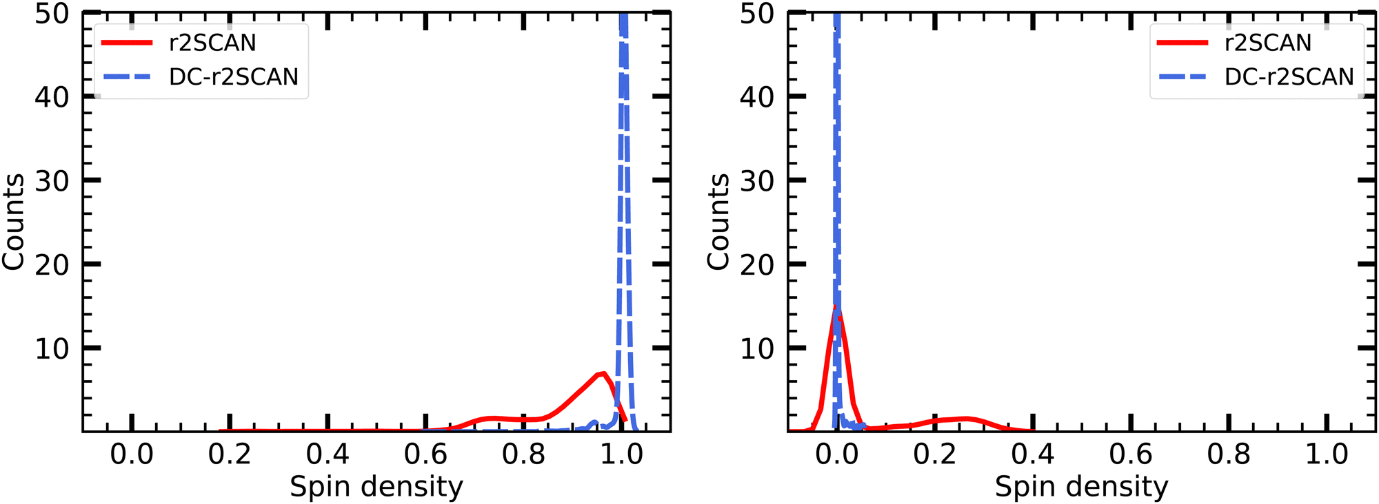
It is worth mentioning that for DC-r2SCAN, the spin charge qA on atom A is determined using the gradient consistent Mulliken analysis
 | (24) |
![[P with combining tilde]](https://www.rsc.org/images/entities/b_char_0050_0303.gif) = P + Pz. This simple metric plays a crucial role in characterizing the obstructed hemibond structure and has recently been used in the hybrid functional analysis of the aqueous hydroxyl radical by Rana and Herbert.28
= P + Pz. This simple metric plays a crucial role in characterizing the obstructed hemibond structure and has recently been used in the hybrid functional analysis of the aqueous hydroxyl radical by Rana and Herbert.28
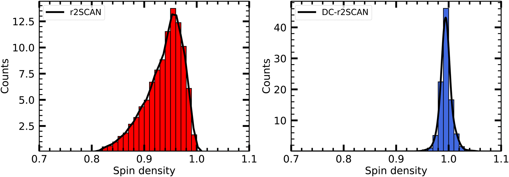
In Fig. 5 we plot the distribution of the spin density for r2SCAN and DC-r2SCAN. The r2SCAN distribution exhibits a stretched-out tail reaching approximately 0.74 in electron charge units, indicating significant spin leakage from the radical to the solvent. Conversely, the spin density distribution in DC-r2SCAN displays a narrow peak at 1.0, confirming the absence of any hemibonded configuration in the O*–O radial distribution function in Fig. 2.
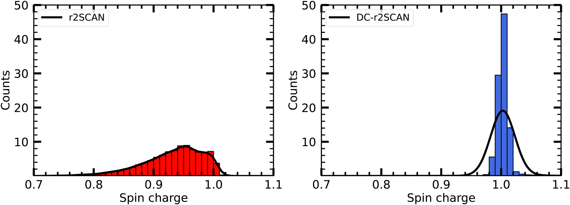 | ||
| Fig. 5 Distribution of Mulliken spin density on ˙OH in solution. | ||
Furthermore, Fig. 6 shows the net average charge of the radical, which are also calculated from summing the Mulliken charges on the atoms of the radical. The net average charge is around 0.057 for r2SCAN and approximately 0.017 for DC-r2SCAN. This outcome is consistent with the reduced likelihood of hydrogen bond formation in DC-r2SCAN, which maintains neutrality in the radical species.
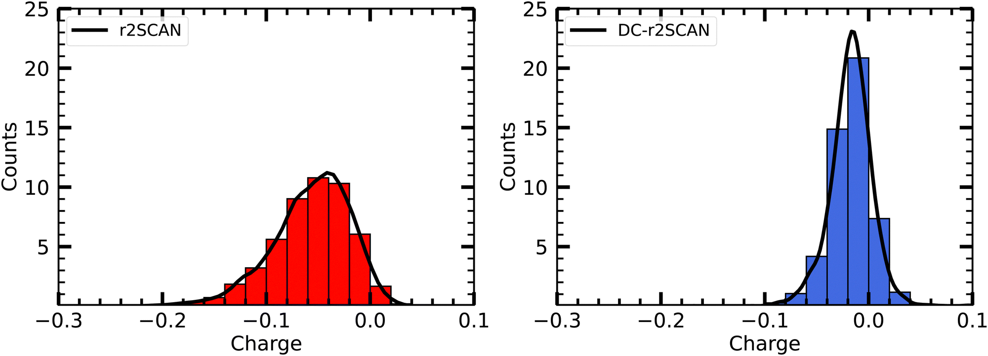 | ||
| Fig. 6 Distribution of Mulliken charge on ˙OH in solution. | ||
The charge and spin charge outcomes align with the self-interaction corrected BLYP results reported by Vandevondele and Sprick,29 reinforcing the possibility that the source of the hemibonded configuration can be attributed to self-interaction errors. The utilization of the Hartree–Fock density instead of the self-consistent Kohn–Sham r2SCAN density helps alleviate density-induced errors responsible for the formation of a (2c-3e)-bonded interaction between the radical and water.
For r2SCAN and DC-r2SCAN, the average dipole moment of the radical is 2.09 ± 0.2 D and 2.05 ± 0.2 D, respectively. Notably, we observe an induced dipole moment by the solvent on the radical of 0.423 D and 0.382 D for r2SCAN and DC-r2SCAN, respectively, based on the reported experimental dipole moment of 1.668 D for the radical in the gas phase.73 The average dipole moment of the solvent water molecules are 2.249 ± 0.2 D and 2.282 ± 0.2 D for r2SCAN and DC-r2SCAN, respectively. However, these outcomes underestimate the experimental dipole moment of 2.95 D.74 The dipole moment distribution of the solvated hydroxyl radical is illustrated in the ESI.†
To address the observed underestimation of the experimental dipole moment, it is important to examine the potential impact of dispersion corrections. The absence of these corrections in our simulations, which account for long-range van der Waals interactions, may contribute to the deviation from the experimental value. By enhancing the attractive forces between water molecules, dispersion corrections can lead to a more ordered structure, increasing the alignment of dipole moments and potentially yielding larger average dipole values. Moreover, the overbinding introduced by dispersion corrections can influence the hydrogen bond network, altering the distribution of dipole moments and consequently impacting the observed average dipole moment.
However, it is important to note that incorporating dispersion corrections, particularly in SCAN and DC-SCAN, has been shown to result in overbinding and compromise energetics.8,9 This trade-off suggests that accurately capturing the dipole moment may come at the expense of deteriorating the system's structural representation and hydrogen bonding network. Exploring alternative approaches, such as utilizing maximally localized Wannier centers, may offer a solution for determining molecular dipole moments, although incorporating the response density in this formalism presents its own challenges.
5.2 Solvated sulfanyl radical
The analysis of the solvated mercapto radical (sulfanyl) ˙SH follows the foodsteps of the solvated hydroxyl radical analysis. Given the lower electronegativity of the Sulfur atom (2.58) compared to oxygen (3.50), we expect – by design – fewer interactions with the solvent.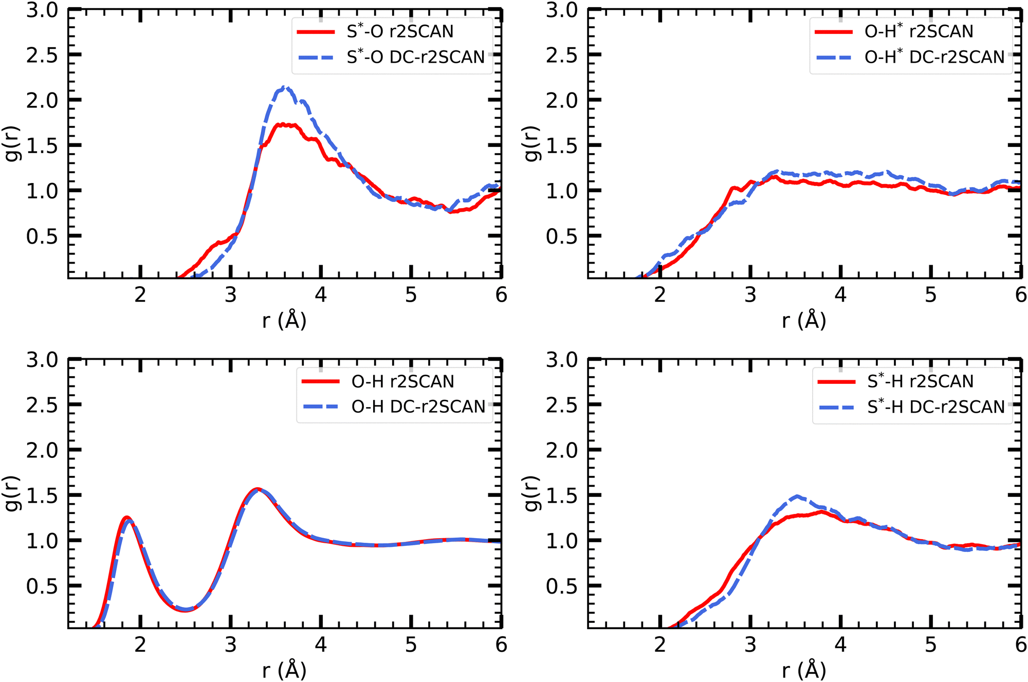 | ||
| Fig. 7 RDFs of S*–O (upper left), O–H* (upper right), O–H (lower left) and S*–H (lower right) for r2SCAN (solid red) and DC-r2SCAN (dashed blue). O (S*) and H (H*) denote the water (sulfanyl) atoms. | ||
In analogy to the solvated hydroxyl radical, the various O–H pair correlation functions in Fig. 7, reveal a first insight on the hydrogen bonding network, and show its, in comparison, much reduced complexity.
The RDF where the ˙SH radical acts as donor (O–H*) does not feature a clearly defined first solvation shell, but instead reaches a peak at 2.82 Å and 3.31 Å for r2SCAN and DC-r2SCAN, respectively. In the case where ˙SH acts as acceptor (S*–H), a weak hydrogen bond can be identified at 3.55 Å and 3.62 Å. We observe that the hydrogen bond length is shorter, and therefore stronger, when the radical is acting as the donor, as opposed to when it is the acceptor.
The absence of hydrogen bonds where the sulfanyl radical acts as donor can also be identified from the (O–H*) radial distribution function. In gas phase CCSD(T)/aug-cc-pV5Z simulations, the hydrogen bond length of the donor bond S*–H*⋯O is 2.19 Å.75 While the onset of the RDF is at approximately 1.9 Å for both methods, the increase is linear until r = 3.29 Å and no peak around 2.19 Å can be identified.
In gas phase simulations at the CCSD(T)/aug-cc-pV5Z level, the hydrogen bond length, where sulfanyl acts as the acceptor, is 2.62 Å. While no distinct peak can be identified around this value, the RDF shows a shoulder in both methods, ranging from 2.2 Å to 2.8 Å. The rate of increase is slower than the curve leading to the peak at 3.78 Å and 3.51 Å.
The hydrogen bond peak between the solvent molecules (O–H) is located at 1.85 Å and 1.88 Å for r2SCAN and DC-r2SCAN, respectively. This result reproduces the solvent in the hydroxyl system. Similarly, the average number of hydrogen bonds between water molecules are 3.56 and 3.53 for r2SCAN and DC-r2SCAN, respectively.
 | ||
| Fig. 8 Mulliken spin charge distribution on ˙SH in solution. | ||
The origin of the smaller predicted molecular dipole moment on the sulfanyl radical with DC-r2SCAN is not entirely clear. The average molecular dipole moment on the water molecules is 2.24 D and 2.27 D with r2SCAN and DC-r2SCAN, respectively. This reproduces the average values encountered for the solvent.
5.3 Hemibonding in radical cation clusters
Sulfur-containing radical cation clusters have recently received significant attention due to their potential relevance in various biological processes, such as redox reactions, enzyme catalysis, and oxidative stress, where sulfur-centered reactive species play essential roles.76 Investigating these clusters provides insights into their reactivity, stability, and implications for biological systems. Notably, clusters such as [CH3S∴CH3SH]+, (CH3SH)2+, and (SH2)n+ exhibit a strong tendency to form (3e-2c) hemibonds, as demonstrated in prior studies.35,77,78 The high reactivity of these hemibonded species limits however direct experimental characterization.In 2018, Xie et al.33 explored the possible structures of [CH3S∴CH3SH]+ in the gas phase. They identified two hemibonded (1a and 1b) and one hydrogen-bonded structure (1c). The geometries of these structures were optimized using B3LYP-D3(BJ)/aug-cc-pVTZ calculations. The two hemibonded structures were found to have similar energies, with (1b) being 0.024 kcal mol−1 higher in energy compared to (1a). On the other hand, the hydrogen-bonded structure exhibited a significantly higher relative energy of 1.936 kcal mol−1 compared to (1a).
To verify the ability of r2SCAN and DC-r2SCAN to distinguish between hydrogen and hemibonded configurations in the radical cation clusters (CH3SH)2+ and (SH2)n+, we performed geometry optimizations of these structures. The computational details can be found in the ESI.†
For (CH3SH)2+, the hemibonded structure (1a) remained the most stable for r2SCAN and DC-r2SCAN. The structures (1a) and (1b) converged to the same geometry. The hydrogen-bonded equilibrium structure (1c) transitioned to the hemibonded motif during optimization with the r2SCAN functional. In DC-r2SCAN, the relative energy of the hydrogen-bonded structure was 7.72 kcal mol−1 higher in comparison to the hemibonded structure. The same procedure was applied to the hydrogen-bonded and hemi-bonded geometries of (SH2)+2.34 The hydrogen-bonded r2SCAN and DC-r2SCAN optimized geometries were 15.87 kcal mol−1 and 15.99 kcal mol−1 higher in energy than the hemi-bonded dimers, respectively. The results for both radical cation clusters confirm the ability of DC-r2SCAN to differentiate between hydrogen-bonded and hemibonded configurations and predict the relative stability of the hemibonded motif in gas-phase calculations.
The identification of hemi-bonded and hydrogen-bonded motifs becomes significantly more intricate when solvation effects need to be considered, since these configurations are already in competition in the gas-phase.34,79,80 Notably, neutral hemibonded radicals have been detected in solvated systems,33 which suggests a potential stabilization mechanism for these (3e-2c)-bonded entities upon solvation. The introduction of solvent molecules introduces novel intermolecular patterns for the hemibonded species, as they can participate in interactions involving hydrogen bonding or even hemibonding with the surrounding solvent molecules.
So far, only the effects of microsolvation have been studied for the closely related CH3SH molecule in heterodimers,38 and the radical cation dimers (CH3SH)2+.81 For the latter, it was found that the hemibonded (CH3SH)2+ ion core was maintained when a single molecule of H2O, (CH3)2CO, or CH3SH was bound, whereas the hemibond was broken by a NH3 molecule, because the proton transfer led to a more stable hydrogen-bonded structure. While solvation effects have been studied for lone SH2 molecules,82–84 the effects of solvation effects on (SH2)2+ have not been investigated yet.
To gain a comprehensive understanding of the behavior of radical cation clusters under realistic solvation conditions, we placed the [CH3S∴CH3SH]+, and [HS∴SH2]+ clusters in a solvation environment consisting of 64 water molecules, using the same simulation protocol as for the hydrated ˙OH and ˙SH radicals.
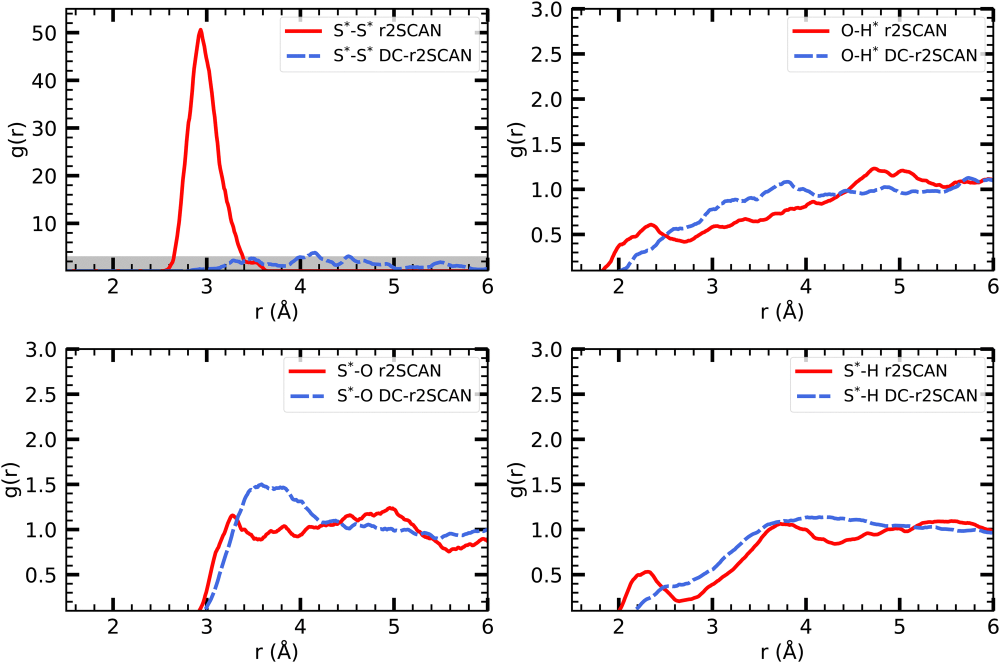 | ||
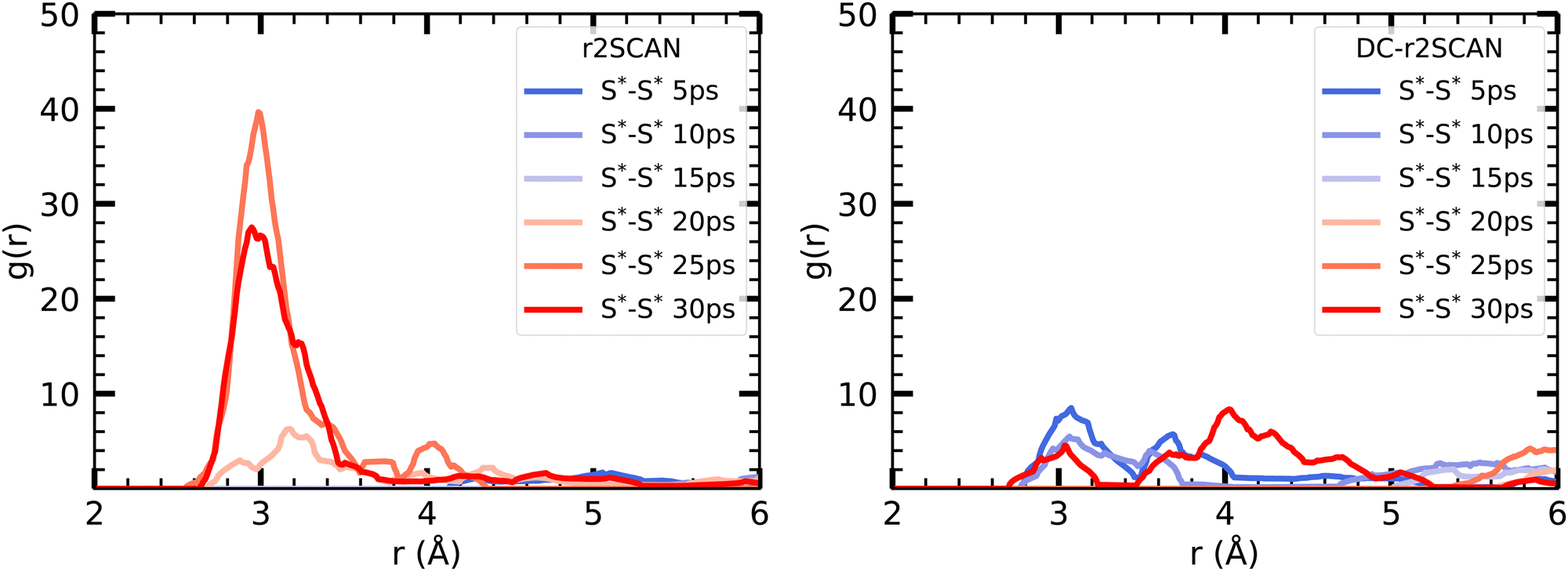
| Fig. 9 RDFs of (upper left) S*–S*, (upper right) O–H*, (lower left) S*–O and (lower right) S*–H for (solid red) r2SCAN and (dashed blue) DC-r2SCAN. The superscript “*” denotes atoms of the solute. | ||
Interestingly, the reported peak is absent in the DC-r2SCAN simulations. Since the DC-r2SCAN MD simulation was started after 15 ps of the r2SCAN AIMD run, where the hemibonded motif existed, further investigation is required. To examine the time-dependent changes, we plot the incremental S–S radial distribution function (RDF) in Fig. 10, with each data point corresponding to a 5 ps interval. We are able to confirm that with r2SCAN, the hemibond continuously exists. In the simulation with DC-r2SCAN, the hemibonded motif briefly exists at the beginning of the AIMD run as a remnant of the starting r2SCAN geometry. Within a few picoseconds, the hemibonded structure is lost and is not recovered during the remainder of the 30 ps trajectory.
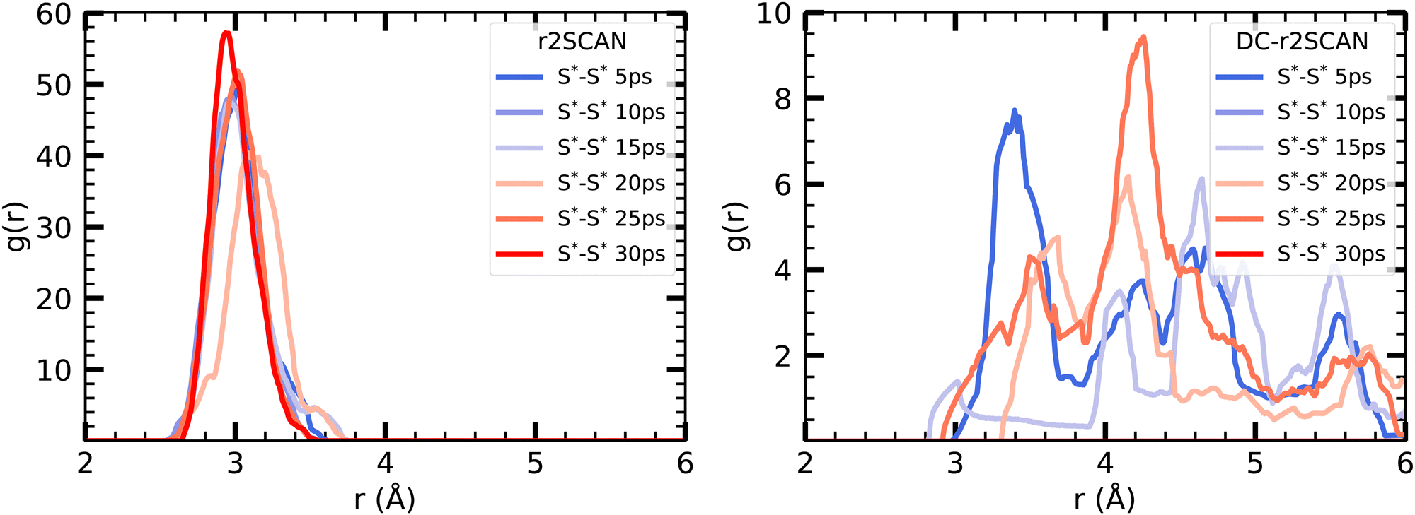 | ||
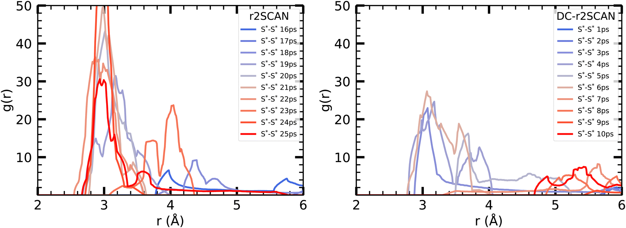
| Fig. 10 Incremental RDFs S*–S* of the sulfur atoms of [CH3S∴CH3SH]+ for (left panel) r2SCAN and (right panel) DC-r2SCAN in 5 ps intervals. The superscript “*” denotes atoms of the solute. | ||
The other RDFs in Fig. 9 describe the solvent interaction with the SH and CH3S moiety. The S*–O RDF provides insights into the solvation behavior of the [CH3S∴CH3SH]+ cluster in water. While the onset of the first solvation shell is similar in both simulations, notable differences can be observed in the peak positions and intensities of the RDF. In the r2SCAN simulation, the first peak occurred at 3.28 Å, extending into a plateau. This indicates a poorly defined second solvation shell. In contrast, the DC-r2SCAN simulation shows a much broader and more intense first peak at 3.59 Å. These differences suggest that in DC-r2SCAN, the cluster molecules are slightly more surrounded by water than with r2SCAN, potentially leading to the destabilization of the hemibond.
Given its electronic configuration, only the CH3SH species is capable of acting as a hydrogen bond donor and thus appears in the O–H* RDF. The results from r2SCAN and DC-r2SCAN are comparable, as no distinct peaks can be identified. However, both the SH moiety of CH3SH and the CH3S moiety can act as hydrogen bond acceptors. In the corresponding RDF (S*–H), r2SCAN shows a peak at 2.24 Å, indicating a slight preference for forming acceptor bonds. This preference may contribute to maintaining the stability of the hemibond, resulting in a more well-defined hydrogen bond network between the solvent and solute. In contrast, DC-r2SCAN does not exhibit this peak, suggesting a lower likelihood of forming acceptor hydrogen bonds. This finding is intriguing, considering the seemingly stronger solvent–solute interactions observed in the S*–O RDF.
In Fig. 11 we show the radial distribution functions of [HS∴SH2]+. In the S*–O RDF, r2SCAN has a first peak at 3.705 Å and DC-r2SCAN at 3.525 Å. This length corresponds to the intermolecular bond lengths between the sulfur atoms of the solvated cluster molecules and H2O, when they are hydrogen bonded and H2S acts as donor 3.56 Å or as acceptor 3.49 Å.85
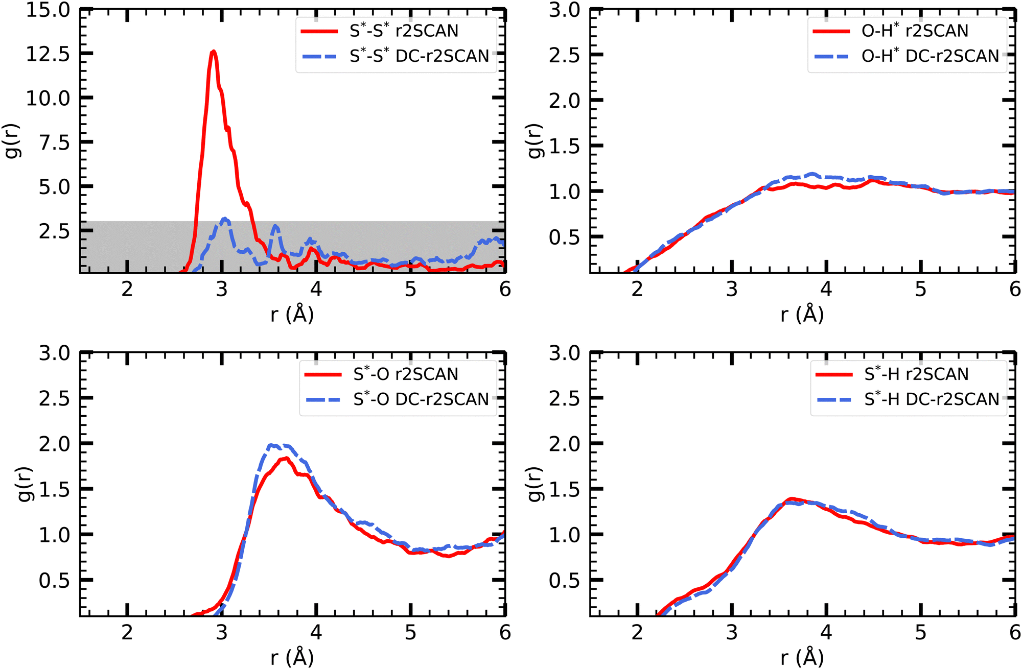 | ||
| Fig. 11 RDFs of (upper left) S*–S*, (upper right) O–H*, (lower left) S*–O and (lower right) S*–H for (solid red) r2SCAN and (dashed blue) DC-r2SCAN. The superscript “*” denotes atoms of the [HS∴SH2]+ cluster. The grayed area indicates the adjusted scale. | ||
The radial distribution function (O–H*) and (S*–H), where the radical cation cluster may act as hydrogen bond donor or acceptor, respectively, show the same trends for r2SCAN and DC-r2SCAN. With either method, no distinct hydrogen bond donor or acceptor peak can be identified. However, the (O–H*) distribution reaches a maximum at 3.65 Å, while the peaks for (S*–H) is located at 3.82 Å.
In the RDF for S*–S*, a large peak is located at 2.915 Å for the r2SCAN functional. Although the DC-r2SCAN method also displays a peak at 3.036 Å, its amplitude is considerably smaller. Notably, Ghanty et al.79 reported a hemibond distance of the sulfur–sulfur ion core of 2.899 Å using the B3LYP method. Additionally, Do and Besley34 found the hemibond distance in the closely related (H2S)2+ system to be 2.83 Å, whereas the hydrogen-bonded distance between S*–S* was larger at 3.62 Å. The DC-r2SCAN RDF exhibits a secondary peak at 3.565 Å, indicating the competitive co-existence of the hydrogen and hemibonded motifs.
To initiate the DC-r2SCAN production run, we used a geometry obtained after 15 ps of the r2SCAN trajectory, following the approach employed for [CH3S∴CH3SH]+. By plotting the incremental RDF in 5 ps intervals in Fig. 12, we observe that the hemibonded motif does not exist after the thermalization in r2SCAN, and is absent during the first 15 ps. However, the peak gradually reappears after 15 ps and grows in strength, becoming the dominant configuration from 20 ps onward. Conversely, the hemibonded motif appears to be the prevailing configuration between the sulfur ionic core in DC-r2SCAN in the first 5 ps of the simulation but subsequently loses in strength as the simulation progresses before it disappears in the interval ranging from 10 to 15 ps. Notably, in the final interval spanning 25–30 ps, the hemibonded motif appears to reestablish itself.
 | ||
| Fig. 12 Incremental S*–S* RDFs of the sulfur atoms of [HS∴SH2]+ for (left panel) r2SCAN and (right panel) DC-r2SCAN in 5 ps intervals. | ||
 | ||
| Fig. 13 Incremental S*–S* RDF [HS∴SH2]+ cluster for (left panel) r2SCAN and (right panel) DC-r2SCAN in 1 ps intervals, starting at the 15 ps mark of r2SCAN (0 ps for DC-r2SCAN). | ||
To gain further insights into the initial 10 ps following the 15 ps mark of the r2SCAN simulation, we examined the incremental RDF at 1 ps intervals, starting from 15 ps for r2SCAN and 0 ps for DC-r2SCAN. In r2SCAN, the peak at 20 Å gradually strengthens, taking 5 ps to develop the hemibonded motif. Similarly, in DC-r2SCAN, the hemibond peak emerges after 3 ps, reaches its maximum amplitude at 6 ps, and subsequently diminishes. In contrast, for [CH3S∴CH3SH]+, the hemibonded motif in the DC-r2SCAN simulation, a remnant of the r2SCAN thermalization, disappeared within the initial 5 ps and made no reappearance.
These findings suggest several intriguing possibilities. First, the continuous presence of the hemibond with r2SCAN in [CH3S∴CH3SH]+ and its immediate disappearance in DC-r2SCAN may be attributed to the strong localization of DC-r2SCAN, promoted by the underlying Hartree–Fock density. Second, the formation of the hemibond with both r2SCAN and DC-r2SCAN in [HS∴SH2]+ and its spontaneous appearance imply that the hemibond does not appear to be stabilized by solvation; instead, it competes strongly against other interactions with the surrounding solvent. Finally, the hemibond is likely to be formed and destroyed repeatedly, with a frequency that extends beyond the available simulation time frame of 30 ps, emphasizing the dynamic and transient nature of the hemibond formation in solvated radical cation clusters.
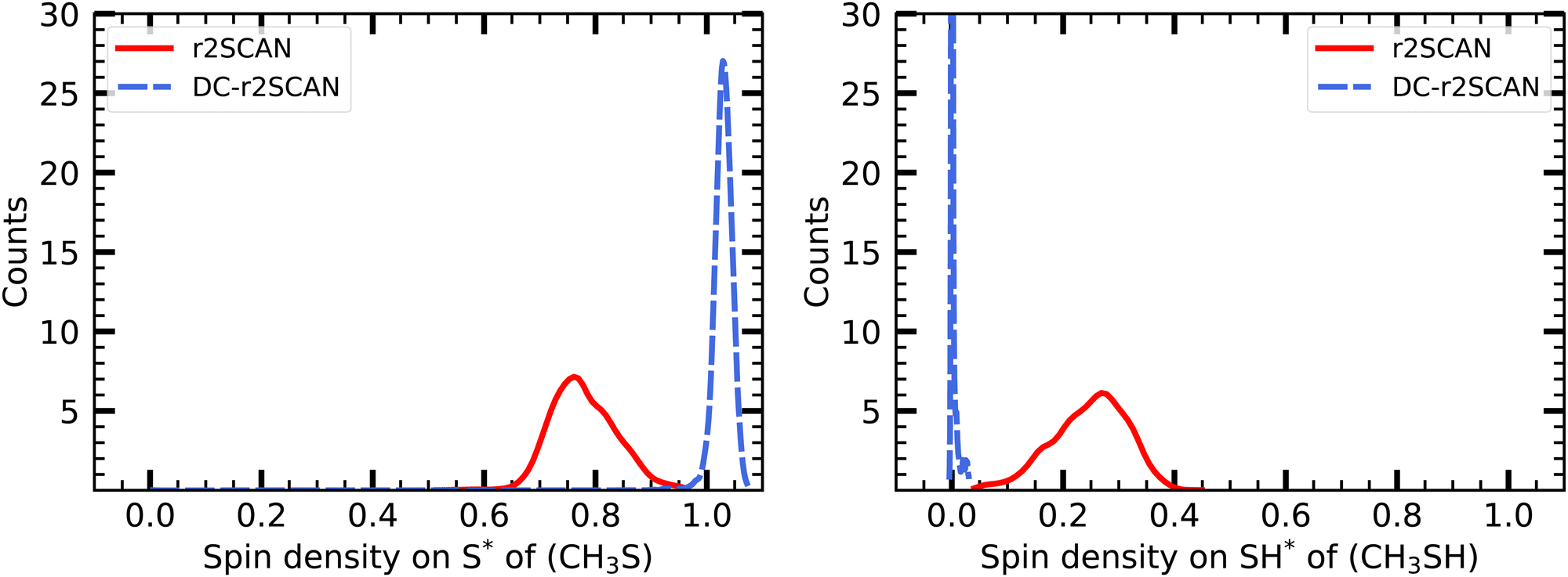 | ||
| Fig. 14 Mulliken spin charge distribution on the (left panel) CH3S, and (right panel) SH moiety of [CH3S∴CH3SH]+. | ||
In Fig. 15 we show the temporal evolution of the Mulliken spin charge, which remains constant throughout the entire simulation for both r2SCAN and DC-r2SCAN simulations. The absence of any spin leakage in DC-r2SCAN is in good agreement with the rapid disappearance of the hemibonded motif depicted in Fig. 10.
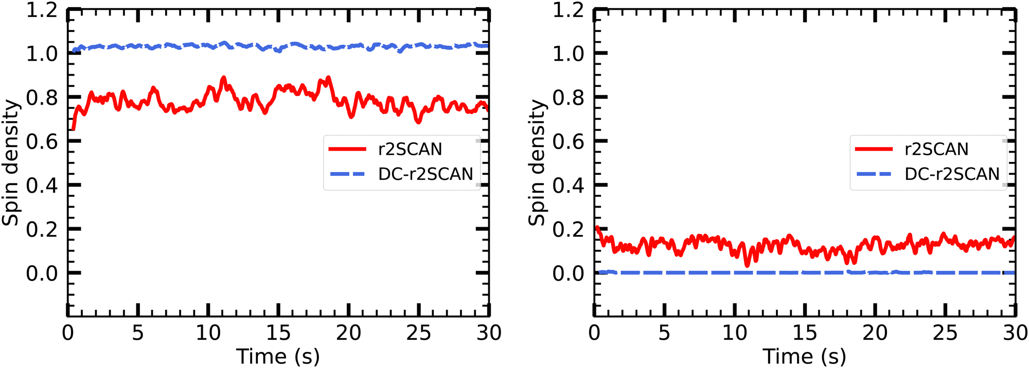 | ||
| Fig. 15 Evolution of Mulliken spin charge distribution on sulfur atom of (left panel) CH3S and SH moiety of [CH3S∴CH3SH]+. | ||
The spin charge distribution of the solvated [HS∴SH2]+ in Fig. 16 reveals the appearance of the hemibonded sulfur–sulfur ion core in the r2SCAN simulations. The spin leakage is however much less pronounced in comparison to the one observed for the [CH3S∴CH3SH]+ cluster with the r2SCAN functional. This is because in contrast to [CH3S∴CH3SH]+, the hemibonded motif only emerges slowly after 15 ps, instead of being present during the entire length of the production run.
 | ||
| Fig. 16 Mulliken spin charge distribution on (left panel) SH and (right panel) SH2 of the solvated [HS∴SH2]+ cluster. | ||
On the other hand, the DC-r2SCAN spin charge appears to be located entirely on the sulfur atom of the SH moiety, in Fig. 16, despite the short-lived emergence of the hemibond after 18 ps, that could be seen in the incremental RDF Fig. 12 and 13. As for r2SCAN, we suspect that the averaged spin charge over the entire production run obscures the dynamical evolution. For this reason, we plot the spin charge as a function of time in Fig. 17. Between 19 ps and 20 ps, the simulation performed with the r2SCAN functional shows the characteristic occurrence of spin leakage, confirming the existence of a hemibond between the sulfur atoms. Even after its formation, the hemibond exhibits strong competition with the hydrogen-bonded motif. This competition is evident through the localization of spin charge on the SH moiety between 23 and 24 ps, as well as from 25.5 to 27.5 ps. The impact of this competition can be observed in Fig. 12 by the reduced peak height of the RDF between 25 and 30 ps, indicating a weakening of the hemibond during that timeframe.
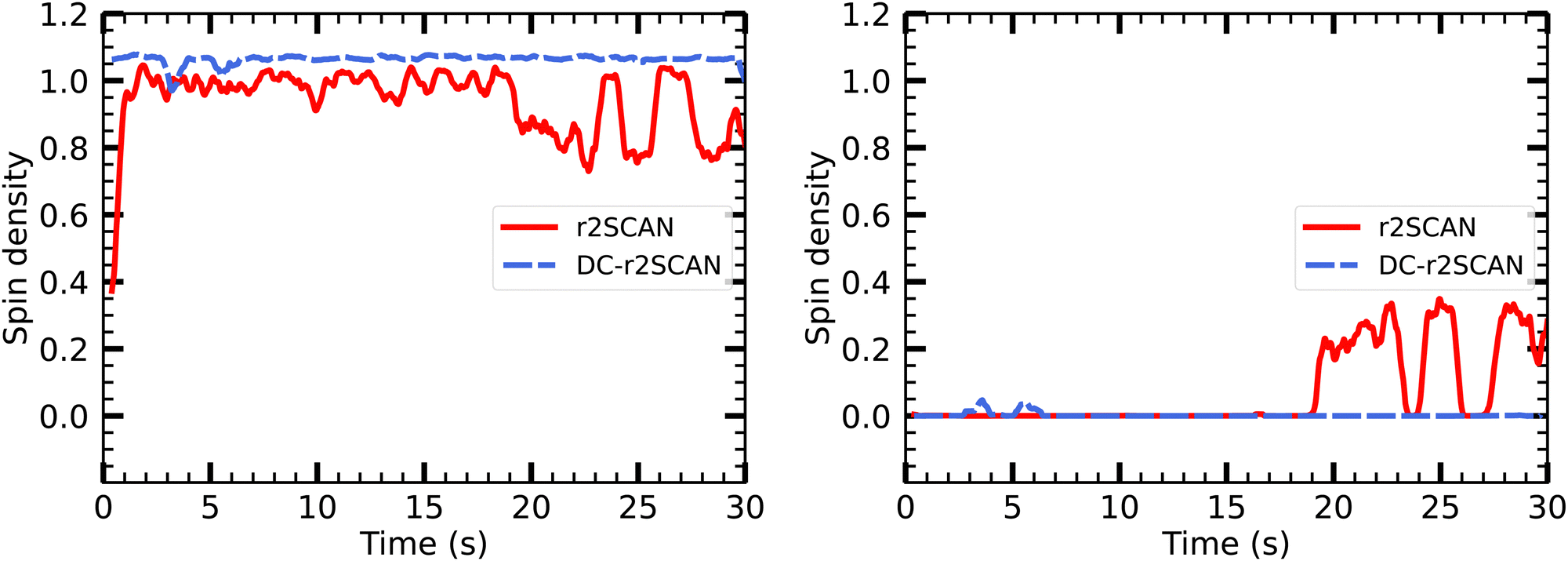 | ||
| Fig. 17 Time evolution of Mulliken spin charge distribution on sulfur atom of (left panel) SH and SH2 of the solvated [HS∴SH2]+ cluster. | ||
Remarkably, the incremental RDF plot of DC-r2SCAN (Fig. 13) exhibits the appearance of a peak around 3 Å, which reaches its maximum intensity between 4 and 6 ps before vanishing. Correspondingly, in Fig. 17, there is a slight yet discernible deviation of the spin charge from 1.06 during the same time period, hinting at the short-lived formation of a hemibond.
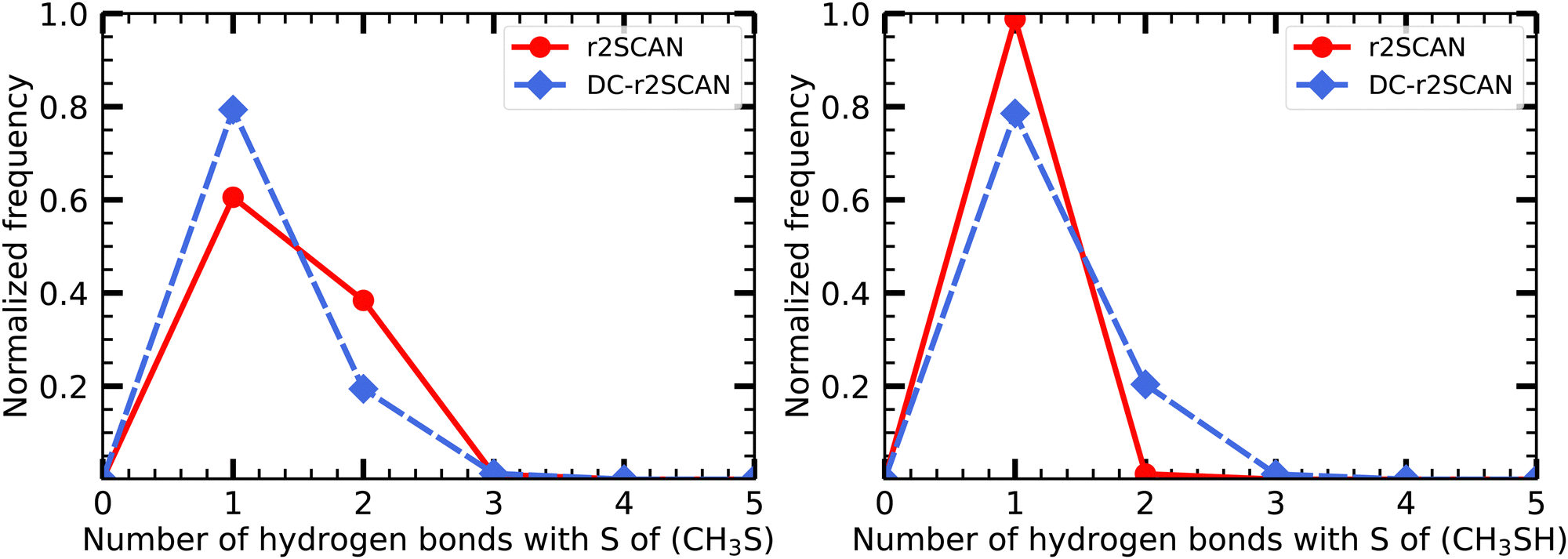 | ||
| Fig. 18 Hydrogen bond distribution involving the (left panel) CH3S moiety and the (right panel) SH moiety of the [CH3S∴CH3SH]+ cluster. | ||
Notably, the sulfur atom of the CH3S moiety can only act as a hydrogen bond acceptor. The r2SCAN functional exhibits a 20% higher likelihood of encountering two acceptor hydrogen bonds compared to DC-r2SCAN, supporting the presence of the observed peak in the S*–H radial distribution function (see Fig. 9). The peak can now be linked to the hydrogen bonding network, characterized by multiple acceptor interactions involving the CH3S moiety. However, the sulfur atom in CH3SH also acts solely as a hydrogen bond acceptor, as shown by the absence of any peak in the O–H* radial distribution function, indicating a lack of donor hydrogen bonding interactions.
Moreover, it is crucial to emphasize that there is an absence of hydrogen bond formation between the CH3S moiety and CH3SH. This observation aligns with previous theoretical investigations77,78 as well as experimental studies86 conducted on analogous methanethiol clusters (CH3SH)n+ with n = 2–5. These studies have revealed that S–H⋯S hydrogen bonding between clusters occurs exclusively for n = 3–5, while no such bonding has been observed in radical cation dimers.
6. Conclusions
This work provides a theoretical study of self-interaction effects in fully solvated and strongly-correlated cationic molecular clusters. The molecular dynamics application of the variational formulation of ADMM accelerated density-corrected DFT has been presented, specifically using the DC-r2SCAN method.The method was successfully validated for bulk liquid water, demonstrating its ability to accurately describe the structure. The DC-r2SCAN method not only reproduces the results obtained with r2SCAN, but also improves upon them by addressing the shortcomings of r2SCAN, particularly related to spin density. This nearly self-interaction free method allows for the observation of hydroxyl radical solvation beyond the GGA approach and accurately reproduces results obtained from self-interaction corrected electronic structure theory methods.
Our study primarily focused on revisiting the solvated hydroxyl radical, and the solvated sulfanyl radical. Subsequently, we extended our investigation to solvated cationic molecular clusters, namely [CH3S∴CH3SH]+ and [HS∴SH2]+. In the case of [CH3S∴CH3SH]+, the DC-r2SCAN simulation revealed the destruction of the initially existing hemibond, which was maintained in the r2SCAN simulation. The observed spin leakage and strong spin charge localization during the DC-r2SCAN simulation supported this finding.
For the solvated [HS∴SH2]+ cluster, the hemibonded motif was lost during thermalization, but r2SCAN was able to restore it, evidenced by the observation of spin leakage. DC-r2SCAN also predicted the formation of a hemibond, although with weaker structural and electronic signatures, indicating a stronger competition from solvent–solute interactions on the survivability of the hemibonded motif.
Future directions for this research include extending the DC-DFT framework by incorporating long-range dispersion corrections and exploring the use of hybrid functionals to improve accuracy. The computational framework developed in this work holds promise for efficiently modeling condensed phase systems with complex correlation effects.
In summary, we demonstrate the effectiveness of self-interaction corrected electronic structure theory, particularly the DC-r2SCAN method, in accurately describing solvated cationic molecular clusters.
Data availability
The CP2K software package can be found at https://github.com/cp2k/cp2k. Data for this paper, including the AIMD trajectories of the solvated radicals and solvated cationic molecular clusters are available at the Materials Cloud Archive at https://archive.materialscloud.org/record/2023.85.Author contributions
Fabian Belleflamme: investigation (equal); methodology (equal); software (equal); validation (equal); visualization (equal); writing – original draft (equal); writing – review & editing (equal). Jürg Hutter: funding acquisition (equal); project administration (equal); resources (equal); software (equal); supervision (equal).Conflicts of interest
There are no conflicts to declare.Acknowledgements
This work was in part funded by the Swiss Platform for Advanced Scientific Computing (PASC) as part of the 2021–2024 “Ab Initio Molecular Dynamics at the Exa-Scale” project. We acknowledge access to Piz Daint and Eiger@Alps at the Swiss National Supercomputing Centre, Switzerland, under the University of Zurichs share with the project no. uzh1.Notes and references
- P. M. Gill, B. G. Johnson, J. A. Pople and M. J. Frisch, Int. J. Quantum Chem., 1992, 44, 319–331 CrossRef.
- N. Oliphant and R. J. Bartlett, J. Chem. Phys., 1994, 100, 6550–6561 CrossRef CAS.
- L. Goerigk, A. Hansen, C. Bauer, S. Ehrlich, A. Najibi and S. Grimme, Phys. Chem. Chem. Phys., 2017, 19, 32184–32215 RSC.
- M.-C. Kim, E. Sim and K. Burke, Phys. Rev. Lett., 2013, 111, 073003 CrossRef PubMed.
- M.-C. Kim, E. Sim and K. Burke, J. Chem. Phys., 2014, 140, 18A528 CrossRef PubMed.
- S. Vuckovic, S. Song, J. Kozlowski, E. Sim and K. Burke, J. Chem. Theory Comput., 2019, 15, 6636–6646 CrossRef CAS PubMed.
- G. Santra and J. M. Martin, J. Chem. Theory Comput., 2021, 17, 1368–1379 CrossRef CAS PubMed.
- S. Dasgupta, E. Lambros, J. P. Perdew and F. Paesani, Nat. Commun., 2021, 12, 1–12 CrossRef PubMed.
- S. Dasgupta, C. Shahi, P. Bhetwal, J. P. Perdew and F. Paesani, J. Chem. Theory Comput., 2022, 18, 4745–4761 CrossRef CAS PubMed.
- E. Palos, E. Lambros, S. Dasgupta and F. Paesani, J. Chem. Phys., 2022, 156, 161103 CrossRef CAS PubMed.
- S. Song, S. Vuckovic, E. Sim and K. Burke, J. Chem. Theory Comput., 2022, 18, 817–827 CrossRef CAS PubMed.
- S. Song, S. Vuckovic, Y. Kim, H. Yu, E. Sim and K. Burke, Nat. Commun., 2023, 14, 799 CrossRef CAS PubMed.
- M.-C. Kim, H. Park, S. Son, E. Sim and K. Burke, J. Phys. Chem. Lett., 2015, 6, 3802–3807 CrossRef CAS PubMed.
- Y. Kim, S. Song, E. Sim and K. Burke, J. Phys. Chem. Lett., 2018, 10, 295–301 CrossRef PubMed.
- J. Sun, R. C. Remsing, Y. Zhang, Z. Sun, A. Ruzsinszky, H. Peng, Z. Yang, A. Paul, U. Waghmare and X. Wu, et al. , Nat. Chem., 2016, 8, 831–836 CrossRef CAS PubMed.
- C. Malosso, L. Zhang, R. Car, S. Baroni and D. Tisi, npj Comput. Mater., 2022, 8, 139 CrossRef CAS.
- J. W. Furness, A. D. Kaplan, J. Ning, J. P. Perdew and J. Sun, J. Phys. Chem. Lett., 2020, 11, 8208–8215 CrossRef CAS PubMed.
- S. Grimme, J. Antony, S. Ehrlich and H. Krieg, J. Chem. Phys., 2010, 132, 154104 CrossRef PubMed.
- E. Caldeweyher, S. Ehlert, A. Hansen, H. Neugebauer, S. Spicher, C. Bannwarth and S. Grimme, J. Chem. Phys., 2019, 150, 154122 CrossRef PubMed.
- E. Sim, S. Song, S. Vuckovic and K. Burke, J. Am. Chem. Soc., 2022, 144, 6625–6639 CrossRef CAS PubMed.
- P. Verma, A. Perera and R. J. Bartlett, Chem. Phys. Lett., 2012, 524, 10–15 CrossRef CAS.
- B. Rana, M. P. Coons and J. M. Herbert, J. Phys. Chem. Lett., 2022, 13, 5275–5284 CrossRef CAS PubMed.
- J. VandeVondele, M. Krack, F. Mohamed, M. Parrinello, T. Chassaing and J. Hutter, Comput. Phys. Commun., 2005, 167, 103–128 CrossRef CAS.
- T. D. Kühne, M. Iannuzzi, M. Del Ben, V. V. Rybkin, P. Seewald, F. Stein, T. Laino, R. Z. Khaliullin, O. Schütt and F. Schiffmann, et al. , Chem. Phys., 2020, 152, 194103 Search PubMed.
- F. Belleflamme, A.-S. Hehn, M. Iannuzzi and J. Hutter, J. Chem. Phys., 2023, 158, 054111 CrossRef CAS PubMed.
- M. Guidon, J. Hutter and J. VandeVondele, J. Chem. Theory Comput., 2010, 6, 2348–2364 CrossRef CAS PubMed.
- M. Guidon, J. Hutter and J. VandeVondele, J. Chem. Theory Comput., 2009, 5, 3010–3021 CrossRef CAS PubMed.
- B. Rana and J. M. Herbert, J. Phys. Chem. Lett., 2021, 12, 8053–8060 CrossRef CAS PubMed.
- J. VandeVondele and M. Sprik, Phys. Chem. Chem. Phys., 2005, 7, 1363–1367 RSC.
- C. Apostolidou, J. Chem. Phys., 2019, 151, 064111 CrossRef.
- E. Codorniu-Hernandez and P. G. Kusalik, J. Chem. Theory Comput., 2011, 7, 3725–3732 CrossRef CAS PubMed.
- B. Rana and J. M. Herbert, Phys. Chem. Chem. Phys., 2020, 22, 27829–27844 RSC.
- M. Xie, Z. Shen, D. Wang, A. Fujii and Y.-P. Lee, J. Phys. Chem. Lett., 2018, 9, 3725–3730 CrossRef CAS PubMed.
- H. Do and N. A. Besley, Phys. Chem. Chem. Phys., 2013, 15, 16214–16219 RSC.
- D. Wang and A. Fujii, Chem. Sci., 2017, 8, 2667–2670 RSC.
- D. Wang, K. Hattori and A. Fujii, Chem. Sci., 2019, 10, 7260–7268 RSC.
- K. Hattori, D. Wang and A. Fujii, Phys. Chem. Chem. Phys., 2019, 21, 16064–16074 RSC.
- X. Sun, M. Xie, W. Qiu, C. Wei, X. Chen and Y. Hu, Phys. Chem. Chem. Phys., 2022, 24, 19354–19361 RSC.
- Y. Saad, Iterative methods for sparse linear systems, Society for Industrial and Applied Mathematics, 2003, pp. 187–216 Search PubMed.
- D. L. Strout and G. E. Scuseria, J. Chem. Phys., 1995, 102, 8448–8452 CrossRef CAS.
- Y. Tawada, T. Tsuneda, S. Yanagisawa, T. Yanai and K. Hirao, J. Chem. Phys., 2004, 120, 8425–8433 CrossRef CAS PubMed.
- J. Spencer and A. Alavi, Phys. Rev. B: Condens. Matter Mater. Phys., 2008, 77, 193110 CrossRef.
- P. Merlot, R. Izsák, A. Borgoo, T. Kjærgaard, T. Helgaker and S. Reine, J. Chem. Phys., 2014, 141, 094104 CrossRef PubMed.
- E. Rebolini, R. Izsak, S. S. Reine, T. Helgaker and T. B. Pedersen, J. Chem. Theory Comput., 2016, 12, 3514–3522 CrossRef CAS PubMed.
- H. Larsen, P. Jørgensen, J. Olsen and T. Helgaker, Chem. Phys., 2000, 113, 8908–8917 CAS.
- C. Kumar, H. Fliegl, F. Jensen, A. M. Teale, S. Reine and T. Kjærgaard, Int. J. Quantum Chem., 2018, 118, e25639 CrossRef.
- A.-S. Hehn, B. Sertcan, F. Belleflamme, S. K. Chulkov, M. B. Watkins and J. Hutter, J. Chem. Theory Comput., 2022, 18, 4186–4202 CrossRef CAS PubMed.
- G. Lippert, J. Hutter and M. Parrinello, Mol. Phys., 1997, 92, 477–488 CrossRef CAS.
- S. Goedecker, M. Teter and J. Hutter, Phys. Rev. B: Condens. Matter Mater. Phys., 1996, 54, 1703 CrossRef CAS PubMed.
- C. Hartwigsen, S. Gœdecker and J. Hutter, Phys. Rev. B: Condens. Matter Mater. Phys., 1998, 58, 3641 CrossRef CAS.
- J. VandeVondele and J. Hutter, Chem. Phys., 2007, 127, 114105 Search PubMed.
- T. T. Duignan, G. K. Schenter, J. L. Fulton, T. Huthwelker, M. Balasubramanian, M. Galib, M. D. Baer, J. Wilhelm, J. Hutter and M. Del Ben, et al. , Phys. Chem. Chem. Phys., 2020, 22, 10641–10652 RSC.
- G. Bussi, D. Donadio and M. Parrinello, J. Chem. Phys., 2007, 126, 014101 CrossRef PubMed.
- L. Martinez, R. Andrade, E. G. Birgin and J. M. Martinez, J. Comput. Chem., 2009, 30, 2157–2164 CrossRef CAS PubMed.
- W. Humphrey, A. Dalke and K. Schulten, J. Mol. Graphics, 1996, 14, 33–38 CrossRef CAS PubMed.
- R. J. Gowers, M. Linke, J. Barnoud, T. J. Reddy, M. N. Melo, S. L. Seyler, J. Domanski, D. L. Dotson, S. Buchoux and I. M. Kenney, et al., MDAnalysis: a Python package for the rapid analysis of molecular dynamics simulations, Los alamos national lab. (lanl), los alamos, NM (United States) technical report, 2019.
- L. B. Skinner, C. Huang, D. Schlesinger, L. G. Pettersson, A. Nilsson and C. J. Benmore, J. Chem. Phys., 2013, 138, 074506 CrossRef PubMed.
- M. Chen, H.-Y. Ko, R. C. Remsing, M. F. Calegari Andrade, B. Santra, Z. Sun, A. Selloni, R. Car, M. L. Klein and J. P. Perdew, et al. , Proc. Natl. Acad. Sci. U. S. A., 2017, 114, 10846–10851 CrossRef CAS PubMed.
- L. Zheng, M. Chen, Z. Sun, H.-Y. Ko, B. Santra, P. Dhuvad and X. Wu, J. Chem. Phys., 2018, 148, 164505 CrossRef PubMed.
- P. M. Piaggi, A. Z. Panagiotopoulos, P. G. Debenedetti and R. Car, J. Chem. Theory Comput., 2021, 17, 3065–3077 CrossRef CAS PubMed.
- J. A. Morrone and R. Car, Phys. Rev. Lett., 2008, 101, 017801 CrossRef PubMed.
- R. A. DiStasio Jr, B. Santra, Z. Li, X. Wu and R. Car, J. Chem. Phys., 2014, 141, 084502 CrossRef PubMed.
- F. Ambrosio, G. Miceli and A. Pasquarello, J. Phys. Chem. B, 2016, 120, 7456–7470 CrossRef CAS PubMed.
- M. Ceriotti, W. Fang, P. G. Kusalik, R. H. McKenzie, A. Michaelides, M. A. Morales and T. E. Markland, Chem. Rev., 2016, 116, 7529–7550 CrossRef CAS PubMed.
- A. Genova, D. Ceresoli and M. Pavanello, J. Chem. Phys., 2016, 144, 234105 CrossRef PubMed.
- A. Luzar and D. Chandler, Phys. Rev. Lett., 1996, 76, 928 CrossRef CAS PubMed.
- A. Soper, F. Bruni and M. Ricci, J. Chem. Phys., 1997, 106, 247–254 CrossRef CAS.
- T. Todorova, A. P. Seitsonen, J. Hutter, I.-F. W. Kuo and C. J. Mundy, J. Phys. Chem. B, 2006, 110, 3685–3691 CrossRef CAS PubMed.
- R. Kumar, J. Schmidt and J. Skinner, J. Chem. Phys., 2007, 126, 05B611 Search PubMed.
- L. D. Jacobson and J. M. Herbert, J. Chem. Phys., 2010, 133, 154506 CrossRef PubMed.
- A. Szabo and N. S. Ostlund, Modern quantum chemistry: introduction to advanced electronic structure theory, Courier Corporation, 2012 Search PubMed.
- M. Thomas, M. Brehm and B. Kirchner, Phys. Chem. Chem. Phys., 2015, 17, 3207–3213 RSC.
- F. Lovas, E. Tiemann, J. Coursey, S. Kotochigova, J. Chang, K. Olsen and R. Dragoset, Diatomic spectral database, NIST standard reference database 114, 2005.
- A. V. Gubskaya and P. G. Kusalik, J. Chem. Phys., 2002, 117, 5290–5302 CrossRef CAS.
- S. Du and J. S. Francisco, J. Chem. Phys., 2009, 130, 124304 CrossRef PubMed.
- R. S. Glass, Sulfur Chem., 2019, 325–366 Search PubMed.
- E. M. Cabaleiro-Lago and J. Rodrguez-Otero, J. Phys. Chem. A, 2002, 106, 7440–7447 CrossRef CAS.
- M. K. Tripathi and V. Ramanathan, RSC Adv., 2021, 11, 29207–29214 RSC.
- T. K. Ghanty and S. K. Ghosh, J. Phys. Chem. A, 2002, 106, 11815–11821 CrossRef CAS.
- T. Stein, C. A. Jimenez-Hoyos and G. E. Scuseria, J. Phys. Chem. A, 2014, 118, 7261–7266 CrossRef CAS PubMed.
- M. Xie, H.-R. Tsai, A. Fujii and Y.-P. Lee, Phys. Chem. Chem. Phys., 2019, 21, 16055–16063 RSC.
- N. J. English and J. S. Tse, J. Phys. Chem. A, 2011, 115, 6226–6232 CrossRef CAS PubMed.
- S. Riahi and C. N. Rowley, J. Phys. Chem. B, 2014, 118, 1373–1380 CrossRef CAS PubMed.
- S. B. Badmos, A. Striolo and D. R. Cole, J. Phys. Chem. C, 2018, 122, 14744–14755 CrossRef CAS.
- K. M. Dreux and G. S. Tschumper, J. Comput. Chem., 2019, 40, 229–236 CrossRef CAS PubMed.
- L. Fu, H.-L. Han and Y.-P. Lee, J. Chem. Phys., 2012, 137, 234307 CrossRef PubMed.
Footnote |
| † Electronic supplementary information (ESI) available. See DOI: https://doi.org/10.1039/d3cp02517a |
| This journal is © the Owner Societies 2023 |