 Open Access Article
Creative Commons Attribution 3.0 Unported Licence
ONIOM meets xtb: efficient, accurate, and robust multi-layer simulations across the periodic table†
Christoph
Plett
 a,
Abylay
Katbashev
 a,
Sebastian
Ehlert
b,
Stefan
Grimme
 *a and
Markus
Bursch
 *c
*c
aMulliken Center for Theoretical Chemistry, Universität Bonn, Beringstr. 4, 53115 Bonn, Germany. E-mail: grimme@thch.uni-bonn.de
bMicrosoft Research AI4Science, Evert van de Beekstraat 254, 1118 CZ Schiphol, The Netherlands
cMax-Planck-Institut für Kohlenforschung, Kaiser-Wilhelm-Platz 1, 45470 Mülheim an der Ruhr, Germany. E-mail: bursch@kofo.mpg.de
First published on 22nd June 2023
Abstract
The computational treatment of large molecular structures is of increasing interest in fields of modern chemistry. Accordingly, efficient quantum chemical approaches are needed to perform sophisticated investigations on such systems. This engaged the development of the well-established “Our own N-layered integrated molecular orbital and molecular mechanics” (ONIOM) multi-layer scheme [L. W. Chung et al., Chem. Rev., 2015, 115, 5678–5796]. In this work, we present the specific implementation of the ONIOM scheme into the xtb semi-empirical extended tight-binding program package and its application to challenging transition-metal complexes. The efficient and broadly applicable GFNn-xTB and -FF methods are applied in the ONIOM framework to elucidate reaction energies, geometry optimizations, and explicit solvation effects for metal–organic systems with up to several hundreds of atoms. It is shown that an ONIOM-based combination of density functional theory, semi-empirical, and force-field methods can be used to drastically reduce the computational costs and thus enable the investigation of huge systems at almost no significant loss in accuracy.
1 Introduction
Current developments and modern techniques for synthesizing and analyzing molecules allow chemists to study increasingly large and complex systems including, e.g., macromolecules, reaction networks, or supramolecular complexes.1–3 Besides a long-standing emphasis on protein structures and their functions in the macro-molecular regime,4 large metal–organic structures such as metal–organic polyhedra (MOP)5,6 or molecular machines7,8 gain growing attention and find application in various fields like drug-delivery processes,9,10 functional materials,11 catalysis,12,13 or fuel storage.14 Such systems can also reach impressive sizes of hundreds to thousands of atoms and may involve moieties with challenging electronic structures. Besides advancing experimental techniques, computational methods and workflows became a valuable utility for a reliable description of large molecular systems enabling deeper insights into basic properties and mechanisms.15,16 However, the application of accurate quantum chemical (QC) methods like density functional theory (DFT) and wave function theory (WFT) methods to extended systems is often limited due to the rapidly increasing computational costs with the system size.17This encouraged the continuous development of force field (FF) and semi-empirical quantum mechanical (SQM) methods that are routinely applied to systems of hundreds up to thousands of atoms.18–21 More recent developments in this field are the GFNn-xTB and force-field methods,22 GFN1-xTB,23 GFN2-xTB,24 and GFN-FF,25 which became widely used and well-established tools for the treatment of large systems.26,27 In contrast to most other semi-empirical approaches and FFs, the GFN methods are consistently parameterized for all elements up to Rn and are thus applicable to a large chemical space throughout the periodic table. These methods are already routinely used in black-box approaches for conformer sampling,28 energetic sorting of structure ensembles,29 or docking algorithms such as the recent aISS30 method with the latter being well-suited for molecule-binding to large structures.14 Nevertheless, complex and challenging electronic structures often require an even more accurate direct or post-processing description at a more sophisticated DFT or WFT level.31
To close this gap, various multi-layer schemes have emerged. They rely on the fact that treating the whole system highly accurately is often unnecessary, but rather a small reactive part or interaction site is of importance.32 For multi-layer schemes, computationally demanding but accurate methods are applied only to a small region of interest while non-negligible environmental effects are treated with computationally cheaper methods. Crucial environmental influences include, e.g., backbone strain in proteins,33 supramolecular stabilization of reactive species,34,35 reaction mechanisms including large structurally strained systems,36 or explicit solvation.37,38 Besides well-known QM/MM schemes,39 the so-called “Our own N-layered integrated molecular orbital and molecular mechanics” (ONIOM) method32,40 proved to be a valuable tool for multi-layer simulations. ONIOM was already successfully applied for modeling organic reactions such as Friedel–Crafts reactions,41 metal–organic catalysis,42 and zeolite reactivity to only name a few.43 In this context, the GFN methods represent a perfect match to simulate the outer region within the ONIOM scheme due to their broad parameterization and reasonable accuracy.19,44–46
Accordingly, we present here the implementation of the ONIOM scheme in the open source xtb program that allows the direct combination of the GFN methods with any desired DFT or WFT method via an interface to the prominent ORCA47,48 or TURBOMOLE49,50 program packages in an easily applicable and intuitive way. This enables the efficient and accurate treatment of not only organic structures but also of molecules containing, e.g., transition metals, heavy main group elements, or even lanthanoids.19,46 Besides the theoretical excursion into the ONIOM approach and its implementation in xtb, we demonstrate its efficient application by investigating molecular geometries and energies of challenging metal–organic structures.
2 Theoretical overview and implementation
In principle, multi-layer techniques used to intermix different levels of QC theory are either additive or subtractive. Additive schemes such as QM/MM or QM/QM were established first and rely on coupling terms between the two regions treated with different methods.51,52 Subtractive schemes like ONIOM do not require additional coupling terms in the Hamiltonian and are thus easier to implement and allow the straightforward mixing of any methods. For the simplest form of the ONIOM scheme, the whole system is divided into two layers: an inner and outer region. These regions are typically treated separately with a high- (Ehighinner) (e.g., DFT) and low-level (Elowouter) method (e.g., SQM or FF) and consequently fused to obtain the ONIOM energy expression:| EONIOM = Ehighinner + Elowouter | (1) |
The low-level description of the outer region is obtained by the subtraction of the energy of the inner region (Elowinner) from the energy of the whole system (Elowwhole) calculated with the corresponding low-level approach:
| Elowouter = Elowwhole − Elowinner | (2) |
In this implementation, no electrostatic embedding is employed for the calculation of the inner region.
If requested, solvation effects can be accounted for by a simplified solvation embedding. Thereby, only Elowwhole is computed embedded in an implicit solvent model while the inner region is always computed in the gas phase.
2.1 ONIOM boundary
The artificial separation of a chemical system into different regions and the creation of the corresponding boundaries between them can be challenging. The trivial case is to deal with boundaries that include only non-covalent interactions. In contrast, treating large molecules with a coupling scheme like ONIOM leads usually to covalent bond breaking. In such cases, the artificial partitioning of the system leads to the formation of radicals or dangling bonds at the boundaries. To address this problem, a number of different approaches were developed32,53 such as the link atom (LA) approach54,55 or the frozen localized orbitals56 approach. Herein, we consider only the former, which is implemented within the xtb software in the course of this work.The general idea behind the link atom saturation technique is the capping of the cleaved bonds to fill the incomplete valence shells of the interface atoms of the partitioned inner region. This is done via the introduction of a dummy atom, usually Hydrogen, on the bond vector between the boundary atoms. The exact position of a link atom is derived as:
![[R with combining right harpoon above (vector)]](https://www.rsc.org/images/entities/i_char_0052_20d1.gif) LA = LA = ![[R with combining right harpoon above (vector)]](https://www.rsc.org/images/entities/i_char_0052_20d1.gif) inner + k( inner + k(![[R with combining right harpoon above (vector)]](https://www.rsc.org/images/entities/i_char_0052_20d1.gif) outer − outer − ![[R with combining right harpoon above (vector)]](https://www.rsc.org/images/entities/i_char_0052_20d1.gif) inner) inner) | (3) |
![[R with combining right harpoon above (vector)]](https://www.rsc.org/images/entities/i_char_0052_20d1.gif) inner and
inner and ![[R with combining right harpoon above (vector)]](https://www.rsc.org/images/entities/i_char_0052_20d1.gif) outer are the coordinates of the atoms in the inner and outer regions with mutual bonds, that split during the ONIOM procedure, and k is the distance scaling factor. Conventionally, k is taken as a constant determined from the predefined element-specific distances between the inner region atom (IA)–outer region atom (OA) and IA-H atoms listed in the ESI.† For cases without listed values, a default value for k is chosen as the ratio of the carbon–carbon/carbon–hydrogen bond distances. As an alternative, we implemented the possibility to make the scaling factor k dependent on the actual value of the IA–OA distance that is present in the system. The corresponding derivatives are given in the ESI.†Fig. 1 demonstrates the ONIOM interpolation scheme, where the chemical system is first partitioned by cleaving its C–C σ bonds, and then saturated with hydrogen atoms via the link atom approach.
outer are the coordinates of the atoms in the inner and outer regions with mutual bonds, that split during the ONIOM procedure, and k is the distance scaling factor. Conventionally, k is taken as a constant determined from the predefined element-specific distances between the inner region atom (IA)–outer region atom (OA) and IA-H atoms listed in the ESI.† For cases without listed values, a default value for k is chosen as the ratio of the carbon–carbon/carbon–hydrogen bond distances. As an alternative, we implemented the possibility to make the scaling factor k dependent on the actual value of the IA–OA distance that is present in the system. The corresponding derivatives are given in the ESI.†Fig. 1 demonstrates the ONIOM interpolation scheme, where the chemical system is first partitioned by cleaving its C–C σ bonds, and then saturated with hydrogen atoms via the link atom approach.
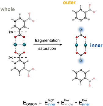 | ||
| Fig. 1 The fragmentation and subsequent saturation procedures within the ONIOM framework. Capping hydrogen atoms are highlighted in blue. | ||
2.2 Topology
One of the distinguishing features of the xtb ONIOM implementation is the usage of the topology information generated with the corresponding GFN method to automate and validate the partitioning and saturation. As cutting double or triple bonds can lead to problematic systems, xtb uses its internal bonding topology data to prohibit the cleavage of higher-order bonds. Moreover, an automatic charge identification routine based on partial charges calculated with the respective GFN method is used to determine the total charge of the inner region automatically.2.3 Jacobian
While the ONIOM single-point energy can be evaluated directly using eqn (1), structure optimizations and frequency calculations require energy derivatives, such as gradients or the Hessian, that need additional treatment. The major complication emerges from the forces introduced by the artificial capping atoms that have to be reassigned accurately to the corresponding real atoms. For this purpose, the Jacobian matrix is used, which is defined as | (4) |
![[g with combining right harpoon above (vector)]](https://www.rsc.org/images/entities/i_char_0067_20d1.gif) highinner) and low-level (
highinner) and low-level (![[g with combining right harpoon above (vector)]](https://www.rsc.org/images/entities/i_char_0067_20d1.gif) lowwhole,
lowwhole, ![[g with combining right harpoon above (vector)]](https://www.rsc.org/images/entities/i_char_0067_20d1.gif) highinner) methods and can be written as
highinner) methods and can be written as![[g with combining right harpoon above (vector)]](https://www.rsc.org/images/entities/i_char_0067_20d1.gif) ONIOM = ONIOM = ![[g with combining right harpoon above (vector)]](https://www.rsc.org/images/entities/i_char_0067_20d1.gif) lowwhole − lowwhole − ![[g with combining right harpoon above (vector)]](https://www.rsc.org/images/entities/i_char_0067_20d1.gif) lowinnerJ( lowinnerJ(![[R with combining right harpoon above (vector)]](https://www.rsc.org/images/entities/i_char_0052_20d1.gif) inner; inner; ![[R with combining right harpoon above (vector)]](https://www.rsc.org/images/entities/i_char_0052_20d1.gif) whole) + whole) + ![[g with combining right harpoon above (vector)]](https://www.rsc.org/images/entities/i_char_0067_20d1.gif) highinnerJ( highinnerJ(![[R with combining right harpoon above (vector)]](https://www.rsc.org/images/entities/i_char_0052_20d1.gif) inner; inner; ![[R with combining right harpoon above (vector)]](https://www.rsc.org/images/entities/i_char_0052_20d1.gif) whole) whole) | (5) |
The formation of the Jacobian matrix requires the differentiation of eqn (3) with respect to the real coordinates (![[R with combining right harpoon above (vector)]](https://www.rsc.org/images/entities/i_char_0052_20d1.gif) whole).
whole).
2.4 Implementation and availability
The ONIOM scheme implemented in the xtb22,57 program package is invoked with one simple command line instruction and can be used as a standalone program with any GFN method combination. Further, it can be interfaced with ORCA or TURBOMOLE to combine DFT/WFT with the GFN methods. The application guideline and installation instructions for the xtb program can be found at the https://xtb-docs.readthedocs.io/en/latest/oniom.htmlxtb-docspage.3 Computational details
All GFN1-xTB, GFN2-xTB, GFN-FF, and ONIOM calculations were performed with the xtb 6.6.0 program package. DFT computations, including also the DFT part for the ONIOM scheme executed and processed by xtb, were performed with TURBOMOLE 7.5.1 or 7.6 except for the solvent clusters where ORCA 5.0.3 was employed. If not stated otherwise, the GBSA58 (SQM, FF) (xtb, toluene), COSMO59,60 (TURBOMOLE, toluene), and CPCM61,62 (ORCA, DMSO) implicit solvation models were used and will be discussed in more detail in Section 4.2.All DFT calculations employ Ahlrichs' def2 Gaussian type atomic orbital basis sets63 and some modified variants developed in the framework of the respective DFT-3c composite methods PBEh-3c64 (def2-mSVP), B97-3c65 (def-mTZVP), and r2SCAN-3c66 (def-mTZVPP). Matching def2 effective core potentials67 were used throughout. If not stated otherwise, the default calculation settings and convergence criteria of the respective codes were applied including the use of the resolution of the identity (RI) approximation with matching auxiliary basis sets.68 The D469–71 London dispersion correction was used throughout.
The systematic workflow for locating transition states was adopted from the work of Dohm et al.72 The double-ended Growing-String Method (GSM) by Zimmerman et al. was used to refine reaction paths73–75 at the GFN2-xTB potential energy surface (PES). The resulting saddle points were further optimized with corresponding density functionals to obtain final transition state geometries. All calculations were executed on an Intel® Xeon® CPU E5-2660 v4 @ 2.00 GHz machine.
4 Results and discussion
In the following, the application of our general ONIOM scheme implementation in xtb is demonstrated for selected showcases ranging from geometry optimizations of MOF cutouts, and explicit solvation of transition metal complexes to reaction mechanism exploration at metal–organic polyhedra.4.1 Molecular structures
A great benefit of multi-layer approaches such as ONIOM is the drastic reduction of computation time compared to a full DFT or WFT approach. This is especially important for geometry optimizations that often represent one of the most time-consuming tasks in computational chemistry workflows.As a demonstration, the following examples show the use of our implementation for geometry optimizations of challenging metal–organic systems. To allow for a fair assessment of the ONIOM results, the showcase systems were selected to still be treatable at a reasonable DFT level. Thus, a direct comparison of the multi-layer combinations and full DFT is possible. As the size of the investigated systems limits the choice of suitable methods, the TPSS76 functional in combination with the def2-SVP basis set was chosen as the DFT approach. Nevertheless, employing the ONIOM scheme would allow for the treatment of much larger structures, where a full DFT treatment even at this low level would be unfeasible.
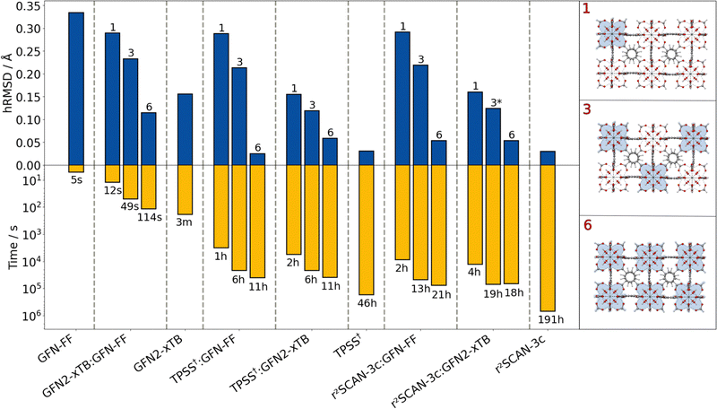
As a first example, a 484 atoms large cutout of the prominent zirconium-based UiO-66 MOF, synthesized by Cavka et al.,77 was examined. Various combinations of GFN and DFT methods were tested within the ONIOM scheme (Fig. 2) for optimizing the geometry. For the ONIOM calculations, the Zr-containing nodes were treated with the high-level method. The resulting method combinations are denoted as “ONIOM(high-level method:low-level method)” in the following. The influence of the inner region size on the ONIOM performance was tested by including one, three, and six Zr nodes. In general, the included Zr nodes were treated as one single extended inner region, not as separated subregions. As a measure of structural quality, the heavy-atom root-mean-square deviation (hRMSD) from the crystal structure is used.
Despite having the largest deviation from the reference, the atomistic GFN-FF is highly efficient in terms of computational timings (5 s). It performs well for the purely organic linker and is still reasonable for the Zr-moiety. The semi-empirical GFN2-xTB shows an improved structure compared to GFN-FF by still remaining computationally efficient (3 min). Applying the ONIOM(GFN2-xTB:GFN-FF) scheme yields a better hRMSD compared to a full GFN-FF optimization already with only one Zr moiety in the inner region. By extending the GFN2-xTB region to the other Zr moieties, the geometry can be improved systematically while still being computationally very efficient. Applying GFN2-xTB to each of the six Zr nodes leads to a slightly lower hRMSD compared to the full GFN2-xTB optimization. The combination of GFN2-xTB for the metal-containing moieties and GFN-FF for the purely organic linker matches the strengths of both methods and yields a very reasonable geometry within seconds up to a few minutes.
The overall lowest hRMSDs are observed for the two DFT methods (TPSS and r2SCAN-3c), but with these methods, the geometry optimization takes several hours up to more than a week for r2SCAN-3c. The combination of DFT methods and GFN-FF does not yield improved hRMSDs over the ONIOM(GFN2-xTB:GFN-FF) approach for the inclusion of one or three Zr nodes. This may be due to asymmetrical distortions of the overall structure which is not the case when six nodes are included in the inner region. Then, the ONIOM(DFT:GFN-FF) combination yields excellent agreement with the reference and the full-DFT treatments. The computation time is reduced from 46 to only 11 hours at no loss in accuracy in case of employing TPSS. The reduction in computational time is even larger for the ONIOM(r2SCAN-3c:GFN-FF) combination (191 hours to 21 hours). Accordingly, the ONIOM approach can save days to weeks of computation time at no relevant loss in accuracy. Noteworthy here is the lower computational time for the inner region including six nodes with the ONIOM(r2SCAN-3c:GFN2-xTB) scheme compared to that including three nodes. This can be explained due to faster convergence of the geometries resulting from the consistent DFT treatment of the zirconium-centered moieties.
Another possible use case of our implementation is the modeling of explicit solvation. If an implicit solvation model becomes insufficient to describe the solvent effect, it is necessary to include explicit solvent molecules which can increase the computational costs tremendously. To still include a sufficient amount of explicit solvents to describe the system accurately, the ONIOM scheme can be used to employ a DFT or WFT method for the solute and a GFN method for the solvent. In this case, no covalent bonds are broken, which renders the GFN methods specifically suitable as they are designed to reproduce non-covalent interactions accurately.
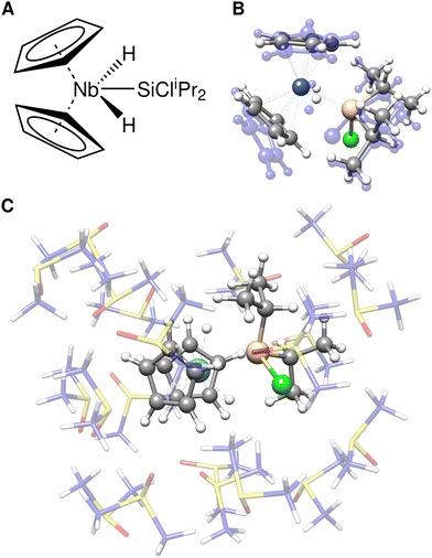
As an example, the Bis(cyclopentadienyl)silylniobium complex [Cp2 Nb(H)2 (SiCliPr2)]78 (Fig. 3A) was solvated with 20 DMSO molecules using the quantum-cluster-growth (QCG) algorithm.30,79 This transition metal complex has previously proven to be a specifically difficult case for common semi-empirical methods in the TMG145 benchmark study.19 The solvated complex was optimized at three different levels, TPSS-D4(CPCM)/def2-SVP (Fig. 3C), GFN2-xTB(ALPB), and ONIOM(TPSS-D4/def2-SVP:GFN2-xTB(ALPB)). In the ONIOM scheme, the bis(cyclopentadienyl)silylniobium complex was chosen as the inner region. A comparison of the cutout solute geometry optimized within the ONIOM scheme and pure GFN2-xTB is shown in Fig. 3B. Optimizing the explicitly solvated complex with TPSS-D4/def2-SVP retains the major structure motif of the Bis(cyclopentadienyl)silylniobium complex with respect to the gas-phase TPSSh80-D3(BJ)-ATM reference structure.19 Using GFN2-xTB for optimizing the whole cluster yields a qualitatively wrong, distorted structure with an RMSD of 0.26 Å of the cutout solute in respect to the fully DFT optimized geometry. Thereby, a haptotropic shift of the cyclopentadienyl ligands occurs and the symmetric coordination of the terminal hydride ligands is distorted. Accordingly, GFN2-xTB is, similar to other semi-empirical and Force Field methods,19 not able to describe this complex system accurately. Applying the ONIOM(TPSS-D4/def2-SVP:GFN2-xTB) scheme instead yields the correct structure in excellent agreement with the full DFT optimization (RMSD of 0.01 Å) at a fraction of computational costs (59 min vs. 48 h 58 min). Despite the good performance of the ONIOM scheme demonstrated for this example, electrostatic embedding may enhance the results for cases with highly polar environments showing strong charge–dependent interactions. Nevertheless, the appropriate choice of the ONIOM boundary may reduce errors in this respect.
4.2 Electronic energies
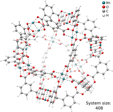
Another key ability of the ONIOM scheme is the calculation of energies for extended structures. This is specifically useful for, e.g., reaction mechanism elucidation, where the chemical transformation is typically occurring at a relatively small reactive site.As a first example, we discuss the Rh-functionalized metal–organic cuboctahedron illustrated in Fig. 4. In the following, it is referred to as DALTES81 in correspondence with its reference code from the Cambridge Structural Database (CSD).82
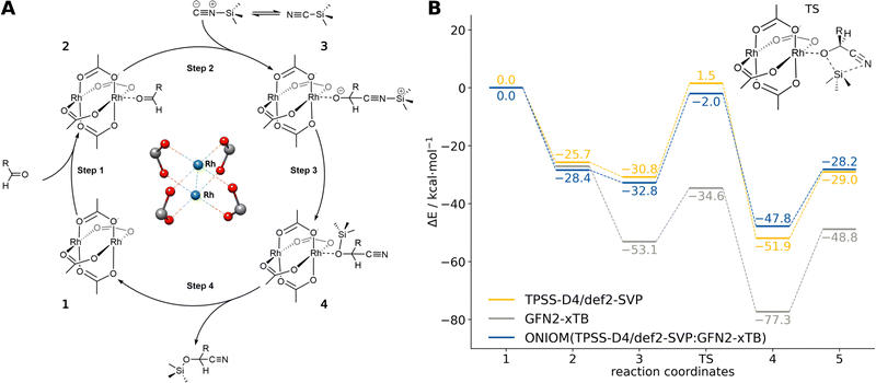
Herein, we consider the cyanosilylation reaction facilitated by the dirhodium paddle-wheel nodes (Fig. 5A). The proposed mechanism depicted in Fig. 5B was adapted from Zhang et al.83 The first step is the coordination of an aldehyde substrate to the open Rh sites of DALTES, which is followed by the nucleophilic addition of the isomerized trimethylsilyl cyanide (iso-TMSCN) to the activated carbonyl compound. Afterwards, the trimethylsilyl group isomerizes into the product which is the rate-determining step of the catalytic reaction. Finally, the produced cyanohydrin derivative is cleaved from the metal cluster of the catalysts. To validate the ONIOM approach, a full quantum mechanical reference energy profile was calculated. Due to the size of the investigated system (404 atoms), the choice of the reference method was again limited to the (meta-)GGA/DZ level. Accordingly, the TPSS-D4/def2-SVP level with COSMO implicit solvation was chosen as a reference and QM component in the ONIOM approach. The energy profile of the catalytic cycle was then recomputed at the GFN2-xTB and ONIOM(TPSS(COSMO):GFN2-xTB(ddCOSMO)) level (Fig. 5). For the ONIOM scheme, only the respective dimetal node involved in the cyanosilylation and the corresponding reactants were included in the inner region.
The semi-empirical GFN2-xTB energy profile qualitatively agrees with the full-DFT results but the relative energies differ by up to 35 kcal mol−1. Applying the ONIOM approach instead yields very good agreement with the TPSS-D4/def2-SVP reference energies, only varying by 1–3 kcal mol−1. Accordingly, the ONIOM scheme can be used to effectively converge the results by combining GFN2-xTB with any suitable DFT method of choice. Using ONIOM reduces the average computational wall time of the energy evaluations from 30 minutes to only 40 seconds. This allows choosing a significantly more accurate method in the inner region that would be unfeasible in a full DFT approach. Similar results are obtained for other methods combinations such as ONIOM(r2SCAN-3c:GFN2-xTB) and ONIOM(ωB97X-3c84:GFN2-xTB) (see ESI†).
An even more challenging system is the recently synthesized porphyrin-based macromolecular spoked-wheel complex by Majewski et al.,85 illustrated in Fig. 6. Its size of 870 atoms renders most conventional DFT methods unfeasible, but the bond formations at the rim of the spoked-wheel complex can be computed employing DFT within the ONIOM approach. The rim of the spoked-wheel complex consists of 18 5,15-linked porphyrin units coordinated by Zn(II) or Ni(II) ions. By the addition of bis(trifluoroacteoxy)iodobenzene (PIFA), the meso–meso coupled Zn–porphyrin rings can be fused further forming a nanobelt involving three-fold single bond coupled Zn–porphyrin units. The corresponding reaction energy of this coupling reaction was computed including the Zinc-functionalized porphyrin rings in the inner region with 432 atoms. The obtained reaction energies are shown in Table 1. The reference method (ONIOM(TPSS:GFN2-xTB(GBSA))) yields an overall reaction energy of −44.9 kcal mol−1. GFN2-xTB and GFN1-xTB yield reasonable reaction energies of −37.6 and −34.9 kcal mol−1, respectively, and show the qualitatively right trend. Using only GFN-FF yields a much too high, qualitatively wrong interaction energy. Combing it with GFNn-xTB within the ONIOM scheme can reduce this error drastically and gives a qualitatively correct behavior. These results show that it is possible to get good and fast results with the ONIOM(GFNn-xTB:GFN-FF) scheme and that, if more accurate results are required for such large systems, ONIOM(DFT:GFN) can be a valuable tool as full DFT calculations are yet too costly.
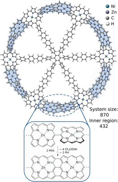 | ||
| Fig. 6 The molecular structure of the 5,15-linked porphyrin nanoring and the fusion reaction between its Zn-functionalized porphyrin units. | ||
| Methods | ΔE/kcal mol−1 | SCF time |
|---|---|---|
| ONIOM(TPSS†:GFN2-xTB) | −44.9 | 25 m |
| GFN2-xTB | −34.9 | 36 s |
| ONIOM(GFN2-xTB:GFN-FF) | −24.4 | 4 s |
| ONIOM(TPSS†:GFN1-xTB) | −47.0 | 24 m |
| GFN1-xTB | −37.6 | 39 s |
| ONIOM(GFN1-xTB:GFN-FF) | −26.6 | 4 s |
| ONIOM(TPSS†:GFN-FF) | −35.3 | 15 m |
| GFN-FF | 172.6 | 0.4 s |
5 Conclusions
In the course of this work, the subtractive ONIOM scheme was implemented into the free, open-source xtb software package. Furthermore, several new implementation-specific features such as an automatic charge and topology handling were introduced. The utility of the ONIOM scheme in combination with the GFN family of semi-empirical and force-field methods was demonstrated exemplary for geometry optimizations and reaction energy evaluations of large metal–organic systems. Various combinations of DFT and GFN methods were tested using the interface of xtb to the popular quantum chemistry packages TURBOMOLE and ORCA.It was shown that the ONIOM approach can be utilized to clearly improve on the already reasonable results of the GFN methods for challenging systems containing many transition metal atoms. By matching the strengths of the GFN methods and DFT, even critical cases that require a highly accurate quantum mechanical description can be treated. Accordingly, we demonstrated that by using the ONIOM framework in xtb, DFT quality reaction energies and molecular structures can be obtained at a fraction of the computational costs of conventional DFT. This allows also the use of computationally more expensive and more accurate DFT methods. The efficient, robust, and easy-to-use implementation of the ONIOM scheme into xtb opens up new possibilities with regard to the treatment of very large systems containing a variety of elements across the periodic table.
Conflicts of interest
There are no conflicts to declare.Acknowledgements
The German Science Foundation (DFG) is gratefully acknowledged for financial support through a Gottfried Wilhelm Leibniz prize to S. G. and the Merck KGaA. Further, S. G. and M. B. gratefully acknowledge financial support of the Max Planck Society through the Max Planck fellow program. Open Access funding provided by the Max Planck Society.References
- I. V. Kolesnichenko and E. V. Anslyn, Chem. Soc. Rev., 2017, 46, 2385–2390 RSC.
- M. S. Gordon, J. M. Mullin, S. R. Pruitt, L. B. Roskop, L. V. Slipchenko and J. A. Boatz, J. Phys. Chem. B, 2009, 113, 9646–9663 CrossRef CAS PubMed.
- S. Kobayashi and H. Uyama, Macromol. Chem. Phys., 2003, 204, 235–256 CrossRef CAS.
- R. Morris, K. A. Black and E. J. Stollar, Essays Biochem., 2022, 66, 255–285 CrossRef CAS PubMed.
- A. C. Ghosh, A. Legrand, R. Rajapaksha, G. A. Craig, C. Sassoye, G. Balázs, D. Farrusseng, S. Furukawa, J. Canivet and F. M. Wisser, J. Am. Chem. Soc., 2022, 144, 3626–3636 CrossRef CAS PubMed.
- D. Fujita, Y. Ueda, S. Sato, N. Mizuno, T. Kumasaka and M. Fujita, Nature, 2016, 540, 563–566 CrossRef CAS PubMed.
- F. Lancia, A. Ryabchun and N. Katsonis, Nat. Rev. Chem., 2019, 3, 536–551 CrossRef CAS.
- J. Kohn, S. Spicher, M. Bursch and S. Grimme, Chem. Commun., 2021, 58, 258–261 RSC.
- S. Mallakpour, E. Nikkhoo and C. M. Hussain, Coord. Chem. Rev., 2022, 451, 214262 CrossRef CAS.
- J. Cao, X. Li and H. Tian, Curr. Med. Chem., 2019, 27, 5949–5969 CrossRef PubMed.
- R. F. Mendes and F. A. A. Paz, Inorg. Chem. Front., 2015, 2, 495–509 RSC.
- A. Bavykina, N. Kolobov, I. S. Khan, J. A. Bau, A. Ramirez and J. Gascon, Chem. Rev., 2020, 120, 8468–8535 CrossRef CAS PubMed.
- M. L. Hu, V. Safarifard, E. Doustkhah, S. Rostamnia, A. Morsali, N. Nouruzi, S. Beheshti and K. Akhbari, Microporous Mesoporous Mater., 2018, 256, 111–127 CrossRef CAS.
- S. Spicher, M. Bursch and S. Grimme, J. Phys. Chem. C, 2020, 124, 27529–27541 CrossRef CAS.
- A. Lledós, Eur. J. Inorg. Chem., 2021, 2547–2555 CrossRef.
- Y. P. Chin, N. W. See, I. D. Jenkins and E. H. Krenske, Org. Biomol. Chem., 2022, 20, 2028–2042 RSC.
- T. S. Hofer, Front. Chem., 2013, 1, 6 Search PubMed.
- W. Thiel, Wiley Interdiscip. Rev.: Comput. Mol. Sci., 2014, 4, 145–157 CAS.
- M. Bursch, H. Neugebauer and S. Grimme, Angew. Chem., Int. Ed., 2019, 131, 11195–11204 CrossRef.
- S. Piana, P. Robustelli, D. Tan, S. Chen and D. E. Shaw, J. Chem. Theory Comput., 2020, 16, 2494–2507 CrossRef CAS PubMed.
- F. Spiegelman, N. Tarrat, J. Cuny, L. Dontot, E. Posenitskiy, C. Martí, A. Simon and M. Rapacioli, Adv. Phys. X, 2020, 5, 1710252 CAS.
- C. Bannwarth, E. Caldeweyher, S. Ehlert, A. Hansen, P. Pracht, J. Seibert, S. Spicher and S. Grimme, Wiley Interdiscip. Rev.: Comput. Mol. Sci., 2021, 11, e1493 CAS.
- S. Grimme, C. Bannwarth and P. Shushkov, J. Chem. Theory Comput., 2017, 13, 1989–2009 CrossRef CAS PubMed.
- C. Bannwarth, S. Ehlert and S. Grimme, J. Chem. Theory Comput., 2019, 15, 1652–1671 CrossRef CAS PubMed.
- S. Spicher and S. Grimme, Angew. Chem., Int. Ed., 2020, 59, 15665–15673 CrossRef CAS PubMed.
- S. Grimme, F. Bohle, A. Hansen, P. Pracht, S. Spicher and M. Stahn, J. Phys. Chem. A, 2021, 125, 4039–4054 CrossRef CAS PubMed.
- Y. Q. Chen, Y. J. Sheng, Y. Q. Ma and H. M. Ding, Phys. Chem. Chem. Phys., 2022, 24, 14339–14347 RSC.
- P. Pracht, F. Bohle and S. Grimme, Phys. Chem. Chem. Phys., 2020, 22, 7169–7192 RSC.
- S. Grimme, F. Bohle, A. Hansen, P. Pracht, S. Spicher and M. Stahn, J. Phys. Chem. A, 2021, 125, 4039–4054 CrossRef CAS PubMed.
- C. Plett and S. Grimme, Angew. Chem., Int. Ed., 2023, 62, e202214477 CrossRef CAS PubMed.
- M. Bursch, J.-M. Mewes, A. Hansen and S. Grimme, Angew. Chem., Int. Ed., 2022, 61, e202205735 CrossRef CAS PubMed.
- L. W. Chung, W. M. C. Sameera, R. Ramozzi, A. J. Page, M. Hatanaka, G. P. Petrova, T. V. Harris, X. Li, Z. Ke, F. Liu, H.-B. Li, L. Ding and K. Morokuma, Chem. Rev., 2015, 115, 5678–5796 CrossRef CAS PubMed.
- N. Koga, R. Koga, G. Liu, J. Castellanos, G. T. Montelione and D. Baker, Nat. Commun., 2021, 12, 1–12 CrossRef PubMed.
- A. Galan and P. Ballester, Chem. Soc. Rev., 2016, 45, 1720–1737 RSC.
- G. Olivo, G. Capocasa, D. Del Giudice, O. Lanzalunga and S. Di Stefano, Chem. Soc. Rev., 2021, 50, 7681–7724 RSC.
- J. Yang, L. Zhao, Y. Sun and H. Sun, ChemPhysChem, 2009, 10, 946–953 CrossRef CAS PubMed.
- M. Ruan, H. Hou, B. Wang, W. Li, Y. Chen, X. Deng and X. Zuo, Theor. Chem. Acc., 2018, 137, 1–10 Search PubMed.
- I. Geronimo and P. Paneth, Phys. Chem. Chem. Phys., 2014, 16, 13889–13899 RSC.
- C. E. Tzeliou, M. A. Mermigki and D. Tzeli, Molecules, 2022, 27, 2660 CrossRef CAS PubMed.
- F. Maseras and K. Morokuma, J. Comput. Chem., 1995, 16, 1170–1179 CrossRef CAS.
- A. Fu, W. Meng, H. Li, J. Nie and J. A. Ma, Org. Biomol. Chem., 2014, 12, 1908–1918 RSC.
- G. Mora, B. Deschamps, S. Van Zutphen, X. F. Le Goff, L. Ricard and P. Le Floch, Organometallics, 2007, 26, 1846–1855 CrossRef CAS.
- Y. Li, W. Guo, W. Fan, S. Yuan, J. Li, J. Wang, H. Jiao and T. Tatsumi, J. Mol. Catal. A: Chem., 2011, 338, 24–32 CrossRef CAS.
- J. Aezáč and J. J. Stewart, J. Chem. Phys., 2023, 158, 44118 CrossRef PubMed.
- S. Schmitz, J. Seibert, K. Ostermeir, A. Hansen, A. H. Göller and S. Grimme, J. Phys. Chem. B, 2020, 124, 3636–3646 CrossRef CAS PubMed.
- M. Bursch, A. Hansen and S. Grimme, Inorg. Chem., 2017, 56, 12485–12491 CrossRef CAS PubMed.
- F. Neese and J. Wiley, Wiley Interdiscip. Rev.: Comput. Mol. Sci., 2012, 2, 73–78 CAS.
- F. Neese, Wiley Interdiscip. Rev.: Comput. Mol. Sci., 2022, 12, e1606 Search PubMed.
- TURBOMOLE V7.6 2021, a development of University of Karlsruhe and Forschungszentrum Karlsruhe GmbH, 1989-2007, TURBOMOLE GmbH, since 2007; available from http://www.turbomole.com Search PubMed.
- R. Ahlrichs, M. Bär, M. Häser, H. Horn and C. Kölmel, Chem. Phys. Lett., 1989, 162, 165–169 CrossRef CAS.
- L. Böselt, M. Thürlemann and S. Riniker, J. Chem. Theory Comput., 2021, 17, 2641–2658 CrossRef PubMed.
- G. A. Bramley, O. T. Beynon, P. V. Stishenko and A. J. Logsdail, Phys. Chem. Chem. Phys., 2023, 25, 6562–6585 RSC.
- H. Lin and D. G. Truhlar, Theor. Chem. Acc., 2007, 117, 185–199 Search PubMed.
- M. J. Field, P. A. Bash and M. Karplus, J. Comput. Chem., 1990, 11, 700–733 CrossRef CAS.
- H. M. Senn and W. Thiel, Top. Curr. Chem., 2007, 268, 173–290 CrossRef CAS.
- G. Tóth and G. Náray-Szabó, J. Chem. Phys., 1994, 100, 3742–3746 CrossRef.
- Semiempirical Extended Tight-Binding Program Package, 2023, https://github.com/grimme-lab/xtb.
- S. Ehlert, M. Stahn, S. Spicher and S. Grimme, J. Chem. Theory Comput., 2021, 17, 4250–4261 CrossRef CAS PubMed.
- A. Klamt and G. Schüürmann, J. Chem. Soc., Perkin Trans. 2, 1993, 799–805 RSC.
- A. Klamt, Wiley Interdiscip. Rev.: Comput. Mol. Sci., 2011, 1, 699–709 CAS.
- V. Barone and M. Cossi, J. Phys. Chem. A, 1998, 102, 1995–2001 CrossRef CAS.
- M. Garcia-Ratés and F. Neese, J. Comput. Chem., 2020, 41, 922–939 CrossRef PubMed.
- F. Weigend and R. Ahlrichs, Phys. Chem. Chem. Phys., 2005, 7, 3297–3305 RSC.
- S. Grimme, J. G. Brandenburg, C. Bannwarth and A. Hansen, J. Chem. Phys., 2015, 143, 054107 CrossRef PubMed.
- J. G. Brandenburg, C. Bannwarth, A. Hansen and S. Grimme, J. Chem. Phys., 2018, 148, 064104 CrossRef PubMed.
- S. Grimme, A. Hansen, S. Ehlert and J. M. Mewes, J. Chem. Phys., 2021, 154, 064103 CrossRef CAS PubMed.
- D. Andrae, U. Häußermann, M. Dolg, H. Stoll and H. Preuß, Theor. Chim. Acta, 1990, 77, 123–141 CrossRef CAS.
- F. Weigend, Phys. Chem. Chem. Phys., 2006, 8, 1057–1065 RSC.
- E. Caldeweyher, C. Bannwarth and S. Grimme, J. Chem. Phys., 2017, 147, 034112 CrossRef PubMed.
- E. Caldeweyher, S. Ehlert, A. Hansen, H. Neugebauer, S. Spicher, C. Bannwarth and S. Grimme, J. Chem. Phys., 2019, 150, 154122 CrossRef PubMed.
- E. Caldeweyher, J. M. Mewes, S. Ehlert and S. Grimme, Phys. Chem. Chem. Phys., 2020, 22, 8499–8512 RSC.
- S. Dohm, M. Bursch, A. Hansen and S. Grimme, J. Chem. Theory Comput., 2020, 16, 8 CrossRef PubMed.
- P. M. Zimmerman, J. Chem. Phys., 2013, 138, 184102 CrossRef PubMed.
- P. M. Zimmerman, J. Chem. Theory Comput., 2013, 9, 3043–3050 CrossRef CAS PubMed.
- M. Jafari and P. M. Zimmerman, J. Comput. Chem., 2017, 38, 645–658 CrossRef CAS PubMed.
- J. Tao, J. P. Perdew, V. N. Staroverov and G. E. Scuseria, Phys. Rev. Lett., 2003, 91, 146401 CrossRef PubMed.
- J. H. Cavka, S. Jakobsen, U. Olsbye, N. Guillou, C. Lamberti, S. Bordiga and K. P. Lillerud, J. Am. Chem. Soc., 2008, 130, 13850–13851 CrossRef PubMed.
- K. Y. Dorogov, A. V. Churakov, L. G. Kuzmina, J. A. Howard and G. I. Nikonov, Eur. J. Inorg. Chem., 2004, 771–775 CrossRef CAS.
- S. Spicher, C. Plett, P. Pracht, A. Hansen and S. Grimme, J. Chem. Theory Comput., 2022, 18, 3174–3189 CrossRef CAS PubMed.
- J. P. Perdew, J. Tao, V. N. Staroverov and G. E. Scuseria, J. Chem. Phys., 2004, 120, 6898 CrossRef CAS PubMed.
- S. Furukawa, N. Horike, M. Kondo, Y. Hijikata, A. Carné Sánchez, P. Larpent, N. Louvain, S. Diring, H. Sato and R. Matsuda, et al. , Inorg. Chem., 2016, 55, 10843–10846 CrossRef CAS PubMed.
- C. R. Groom, I. J. Bruno, M. P. Lightfoot and S. C. Ward, Acta Crystallogr., Sect. B: Struct. Sci., Cryst. Eng. Mater., 2016, 72, 171–179 CrossRef CAS PubMed.
- Z. Zhang, J. Chen, Z. Bao, G. Chang, H. Xing and Q. Ren, RSC Adv., 2015, 5, 79355–79360 RSC.
- M. Müller, A. Hansen and S. Grimme, J. Chem. Phys., 2023, 158, 14103 CrossRef PubMed.
- M. A. Majewski, W. Stawski, J. M. V. Raden, M. Clarke, J. Hart, J. N. O'Shea, A. Saywell and H. L. Anderson, Angew. Chem., Int. Ed., 2023, 62, e202302114 CrossRef CAS PubMed.
Footnote |
| † Electronic supplementary information (ESI) available. See DOI: https://doi.org/10.1039/d3cp02178e |
| This journal is © the Owner Societies 2023 |

