 Open Access Article
Characteristic growth of chemical gardens from mixtures of two salts†
Yujin
Kubodera
a,
Yu
Xu
ab,
Yuta
Yamaguchi
a,
Muneyuki
Matsuo
 a,
Masashi
Fujii
 a,
Maya
Kageyama
c,
Oliver
Steinbock
 d and
Satoshi
Nakata
 *a
*a
aGraduate School of Integrated Sciences for Life, Hiroshima University, 1-3-1 Kagamiyama, Higashi-Hiroshima 739-8526, Japan. E-mail: nakatas@hiroshima-u.ac.jp; Tel: +81-824-24-7409
bSchool of Chemistry and Chemical Engineering, Northwestern Polytechnical University, Chang'an campus 1 Dongxiang Road, Chang'an District, Xi'an Shaanxi 710129, P. R. China
cSchool of Science, Kwansei Gakuin University, Sanda, Hyogo 669-1337, Japan
dDepartment of Chemistry and Biochemistry, Florida State University, Tallahassee, Florida 32306-4390, USA
First published on 10th April 2023
Abstract
Chemical gardens formed from two metal salts (MCl2 or MSO4) have been investigated to understand the effects of mixing on the growth of precipitate tubes. The growth of tubes can be classified into three types, i.e., collaborative, inhibited, and individual growth, depending on the combination of the two metal salts. Characteristic features of tube growth are discussed in relation to the flow near the tip of the tube controlled by osmotic pressure and the solubility product, Ksp, for M(OH)2. The present study can be interpreted as an inanimate model system of symbiosis among different species, such as mixed cropping systems and survival among different kinds of microbial cells.
Introduction
Chemical gardens are precipitates of metal salts forming semipermeable membranes. They are frequently studied as model systems of pattern formation under nonequilibrium conditions.1–5 For the past four centuries, numerous studies on these fascinating precipitation patterns have been reported. These studies focused on various physicochemical factors6–15 including oscillatory growth of hollow microtubes,12 tube growth with a pinned bubble,14 and spiral growth of the tube controlled by the application of magnetic force.15 Recently, chemical gardens have received attention as biomimetic materials due to their ability to form a variety of self-assembled structures,16–27 such as silica-rich biomimetic mineral20 and self-assembled nanostructures.21–27 These diverse approaches to chemical gardens and their self-organizing processes in physics, chemistry, and biology nucleated a new research area called “chemobrionics”.1,21–26 In addition, the morphology and composition of the chemical gardens under different conditions have been studied using various analytical methods and techniques.28–35 A few recent studies also investigated chemical gardens consisting of multiple chemical species.32,35 Of particular interest was that the changes in the mixing ratio of the reactants greatly influenced the growth rate, composition, and morphology of the resulting chemical gardens.35 However, their nature has not been clarified yet.In this paper, mixed powders composed of two different metal salts (selected from FeSO4, CuSO4, CoSO4, CaSO4, and CaCl2) were spread as a thin strip on the bottom of a vertical Hele-Shaw cell and subjected to a silicate aqueous solution. The growth rates of the tubes changed characteristically depending on the combination of two species and the ratio of their amounts. These dependencies revealed collaborative, inhibited, and individual growth effects. Our results are discussed in relation to the solubility product of M(OH)2 and the osmotic pressure depending on the flow rate. In addition, we suggest that these growth types could serve as an inanimate model system of symbiotic relationships between two species such as plants showing mutualism or competitive growth.38
Experimental method
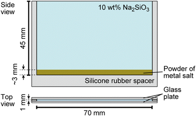
Sodium silicate aqueous solution (Na2SiO3, CAS 31933-85), cobalt (II) sulfate heptahydrate (CoSO4·7H2O, > 98%, CAS 09229-15), calcium sulfate dihydrate (CaSO4·2H2O, > 98%, CAS 10101-41-4), calcium chloride (CaCl2, > 98%, CAS 10043-52-4), sodium chloride (NaCl, > 99.5%, CAS 7647-14-5), and iron (II) sulfate heptahydrate (FeSO4·7H2O, > 98%, CAS 7782-63-0) were purchased from Nacalai Tesque, Inc. (Kyoto, Japan). Copper (II) sulfate pentahydrate (CuSO4·5H2O, > 98%, CAS 7758-99-8) was purchased from Wako Pure Chemical Industries, Ltd. (Osaka, Japan). Glass beads (ASGB-60, diameter: 250–355 μm) were purchased from AS ONE Corporation (Osaka, Japan). Spherical polymer beads (G0200, diameter: 2.0 μm) were purchased from Thermo Fisher Scientific (California, America).The growth of the chemical garden was monitored using a digital video camera (SONY, HDR-CX430, the minimum time resolution: 1/30 s, Tokyo, Japan) from side views, and the obtained movies were analyzed using image processing software (ImageJ, National Institute of Health, Bethesda, MD, USA). Water was first distilled and then purified with a Millipore Milli-Q filtering system (resistance: 18 MΩ cm). A vertical Hele-Shaw cell, schematically shown in Fig. 1, was prepared for the experiment according to the following steps: (1) A silicone rubber sheet was introduced as a spacer and covered with two parallel glass plates. (2) Metal salts were crushed with a mortar and a pestle to obtain smaller solid particles (diameter: 0.2 ± 0.1 mm for FeSO4, CuSO4, CoSO4, 0.4 ± 0.3 mm for NaCl, 0.04 ± 0.03 mm for CaCl2, and 0.02 ± 0.01 mm for CaSO4). (3) Two of these powders were homogeneously mixed, and the mixed sample (mass: 0.2 g) was then spread on the bottom of the cell. The resulting thickness of the salt layer was ∼3 mm. (4) 10 wt% Na2SiO3 aqueous solution (volume: 3 mL, concentration: 0.6 M, pH = 12.0) was carefully poured on the layer of metal salts and filled up to the top of cell. Here, we defined t = 0 as the time when an aqueous Na2SiO3 solution was added onto the layer.
 | ||
| Fig. 1 Schematic illustration of the experimental system used for the characterization of chemical garden growth. | ||
To evaluate the flow rate near the tip of the tube, Ft, spherical polymer beads were added to the aqueous Na2SiO3 solution. The tube formation was observed with a video camera mounted on a microscope (GLB-T3M, SHIMADZU, Tokyo, Japan) that was placed on its side.
All experiments were performed in an air-conditioned room at 298 ± 2 K. At least three measurements were examined for each sample to confirm reproducibility.
Results
Growth of chemical garden tubes from single metal salts
At first, we examined the growth of chemical garden tubes from pure metal salts (FeSO4, CoSO4, CaCl2, CuSO4, and CaSO4) in our quasi-two-dimensional setup. Image sequences and our measurements of the average length of the tubes at time t (min), Lt, are shown in Fig. S1 and S2 (ESI†), respectively. The order of Lt was CuSO4 > FeSO4 > CoSO4 > CaCl2 > CaSO4. Tubes were observed for every metal salt except CaSO4.To investigate the effects of the number density of the metal salt particles on tube growth, different amounts of inert glass beads were mixed with FeSO4 or CuSO4 and used as the solid phase, as shown in Fig. S3 (ESI†). These experiments showed that for a range of 10–100 wt%, Lt at t = 10 min, L10, was almost independent of the density of both FeSO4 and CuSO4.
Growth of chemical garden tubes from mixtures composed of two different metal salts
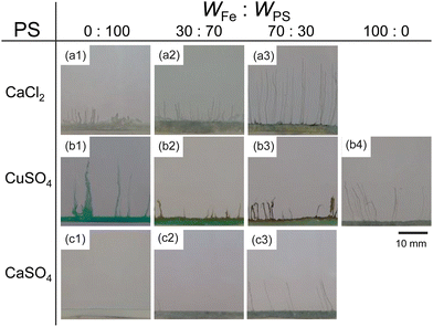
Next, we examined the mixtures composed of two different metal salts. Fig. 2 shows snapshots of chemical gardens grown from mixtures of two kinds of metal salts with different ratios at t = 10 min. The length of the tubes at t = 10 min changed characteristically with the combination of the mixture. The length of the tubes grown from a mixture of 70 wt% FeSO4 and 30 wt% CaCl2 was longer than length of those produced from pure metal salts (see Fig. 2a3). In contrast, the lengths of the tubes from mixtures of FeSO4 and CuSO4 were shorter than the lengths of those produced from the respective individual metal salts (see Fig. 2b2 and b3). Furthermore, we found that the length of the tubes from a mixture of 70 wt% FeSO4 and 30 wt% CaSO4 was equal to that of tubes grown from 100 wt% FeSO4 (see Fig. 2c3 and b4). Snapshots for the other combinations of mixtures, i.e., CaCl2 and CoSO4, CaCl2 and CuSO4, CaSO4 and CoSO4, CaSO4 and CuSO4, CoSO4 and CuSO4, and CoSO4 and FeSO4 are shown in Fig. S4 (ESI†).To evaluate the effect of the mixing ratio on tube growth, we systematically measured L10 (see Fig. 3). Notice that short tubes (L10 < 5 mm) were ignored in this analysis. We identified three types of tube growth in the mixed samples. L10 for a mixture of CaCl2 and FeSO4 was greater than that for single metal salts, specifically at a mixing ratio of 60–90 wt% FeSO4 (see the green region in Fig. 3a), that is, the growth of tubes was promoted by mixing. We called such a growth type “collaborative growth”. L10 for a mixture of CuSO4 and FeSO4 was smaller than that for single metal salts when mixed together (see the red region in Fig. 3b), that is, the growth was suppressed by mixing. We called this growth type “inhibited growth”. As for a mixture of CaSO4 and FeSO4, L10 at 10–40 wt% FeSO4 was zero which was the same value as that at 100 wt% CaSO4, but L10 at 50–90 wt% FeSO4 was similar to that at 100 wt% FeSO4 (see Fig. 3c), that is, L10 for the mixture of CaSO4 and FeSO4 was determined from L10 for a single metal salt either CaSO4 or FeSO4. We called this growth type “individual growth”. Time-variations of Lt for these mixtures exhibited similar trends (see Fig. S5, ESI†).
L 10 values for the other combinations of mixtures, i.e., CaCl2 and CoSO4, CaCl2 and CuSO4, CaSO4 and CoSO4, CaSO4 and CuSO4, CoSO4 and CuSO4, and CoSO4 and FeSO4 are shown in Fig. S6 (ESI†). The mixtures of CaCl2 and CoSO4 and CaCl2 and CuSO4 were classified as exhibiting “collaborative growth”. The mixture of CoSO4 and FeSO4 was classified as exhibiting “inhibited growth”. The mixtures of CaSO4 and CoSO4 and CaSO4 and CuSO4 were classified as displaying “individual growth”.
The number of tubes at t = 10 min, n10, and their total width of all tubes, ΣA10/L10, depending on the ratio of FeSO4 are shown in Fig. S7 and S8 (ESI†), respectively. Here, ΣA10 is the sum of the area of the tube, as measured from side views at t = 10 min. They exhibited similar trends to the results in Fig. 3.
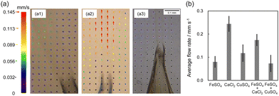
Upward flow was observed near the tip of the tubes (see Fig. 4 and Movies S1–S3, ESI†). In particular, a strong upward flow was observed for 100 wt% CaCl2 (see Movie S4, ESI†). The average flow rate for a mixture of 40 wt% NaCl and 60 wt% FeSO4 (0.13 ± 0.05 mm s−1) was faster than that of single FeSO4 (0.08 ± 0.02 mm s−1), and the tube growth with greater width and branching was observed.
For collaborative and individual growth patterns, upward flow was maintained during the tube formation (see Fig. S9a, ESI†). In contrast, for inhibited growth, the flow rate, Ft, decreased when the tube growth reduced, and reached zero when the tube growth stopped (see Fig. S9b, ESI†). The average value of Ft varied according to the following order: 100 wt% CaCl2 > 20 wt% CaCl2 and 80 wt% FeSO4 > 100 wt% CuSO4, > 100 wt% FeSO4 > 50 wt% CuSO4 and 50 wt% FeSO4 (see Fig. 4b). In addition, the average value of Ft for collaborative growth (0.17 ± 0.03 mm s−1 for 20 wt% CaCl2 and 80 wt% FeSO4) was faster than the weighted average of 20% CaCl2 and 80% FeSO4 (0.2 × (0.24 ± 0.04) + 0.8 × (0.08 ± 0.03) = 0.11 ± 0.03 mm s−1). The average value of Ft for inhibited growth (0.06 ± 0.03 mm s−1 for 50 wt% CuSO4 and 50 wt% FeSO4) was lower than the weighted average 50% CuSO4 and 50% FeSO4 (0.10 ± 0.02 mm s−1).
Discussion
We now discuss the mechanism giving rise to the three types of tube growth in a two-component mixed system based on previously proposed mechanisms of chemical gardens.1,5,6,10–12,28–32At first, solid particles of metal salts dissolve in the water phase, as indicated by the reaction (1).
| MSO4(s) → M2+ (aq) + SO42− (aq) |
| or MCl2(s) → M2+ (aq) + 2Cl− (aq) | (1) |
Then a semipermeable membrane is formed on the solid layer according to reaction (2).
| M2+(aq) + OH−(aq) → M(OH)2 (s) | (2) |
We note that these reactions typically include other ionic species such as MOH+ (aq),37 which will not be considered in our discussion.
The osmotic pressure between the inside and outside of the membrane increases due to the dissolution of metal salt. As a result, water molecules traverse the membrane28,29 and the pressure difference between the interior and exterior increases. This process ultimately induces the local rupture of the membrane. From this ruptured site, M2+ solution is ejected and the tube is formed from a reaction between OH− and M2+ ions.
The growth of tubes in this study is described using two important factors. First is the flow near the tip of the tube which is driven by osmosis.5 The order of Ft for the single metal salt systems, CaCl2 ≫ FeSO4 > CuSO4, is related to the order of their dissolution rates in water, i.e., CaCl2 ≫ FeSO4 ≈ CuSO4, (see section 12 in ESI†). This is because the osmotic pressure as a driving force of Ft becomes larger with an increase in the difference in the concentration between inside and outside of the membrane. The lack of tube growth in CaSO4 may be attributed to its low dissolution rate which is not sufficient to generate osmotic pressure for rupturing the membrane and ejecting M2+ solution.
The second significant factor for the growth is the membrane formation. According to the previous research, the contribution of SiO32− is surprisingly low in chemical gardens, regardless of the SiO32− concentration employed.1,36 Therefore, in our discussion, we focus on the solubility product between OH− and M2+ ions, Ksp, as an indicator of ease of membrane formation. The growth rates for single metal salt followed a descending order of (see Fig. S2, ESI†) CuSO4 > FeSO4 > CoSO4 > CaCl2 ≫ CaSO4, which was the same as the ascending order of the Ksp values between OH− and M2+ ions, i.e., Ca(OH)2 > Co(OH)2 ≈ Fe(OH)2 > Cu(OH)2 (see Table S1, ESI†) since the lower Ksp values result in easier formation of the membrane.27 Actually, the color of the tube obtained from FeSO4 was white which corresponded to Fe(OH)2.39 Fig. S3 (ESI†) suggests that the amount of metal salts does not affect the growth rate of the chemical garden tube above 10 wt% metal salt and that 10 wt% metal salt is enough for the tube to grow without the need for other metal salt. The minimum concentrations of metal salts for producing the precipitation of M(OH)2 based on the pH value of the aqueous solution (= 12.0), and the calculation procedure are indicated in Table S1 (ESI†). Considering the data in Table S1 (ESI†), membrane formation is assumed to occur from the moment the particles encounter aqueous Na2SiO3 solution, that is, even 10 wt% particles with glass beads can generate enough tubes on exposure to aqueous Na2SiO3 solution.
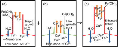
The mechanism of the three growth types could be explained, as follows. Collaborative growth occurs in the mixtures containing CaCl2, i.e., CaCl2 and FeSO4, CaCl2 and CuSO4, and CaCl2 and CoSO4. The formation of a membrane from CaCl2 is not easy due to the larger value of Ksp for Ca(OH)2 (see Fig. 5b and Table S1, ESI†). In contrast, a M(OH)2 membrane is easily formed due to the small value of Ksp for Fe(OH)2, Cu(OH)2 or Co(OH)2 (see Fig. 5a and Table S1, ESI†). As CaCl2 dissolves more rapidly in water (see Table S2, ESI†), the osmotic pressure increases, which in turn increases Ft, and the solution is ejected from the tip of the tube (see Fig. 4). As a result, M2+ ions in the ejected solution can react with OH− ions located near the tip of the tube more readily (see Fig. 5).
Low values of Ft at inhibited growth suggest that the transfer of H2O molecules from outside to inside of the membrane is reduced by the formed membrane (see Fig. 4b and Fig. S9, ESI†). As the values of Ksp for Fe(OH)2, Cu(OH)2, and Co(OH)2 are very small in comparison with those for Ca(OH)2, co-precipitation of these metal hydroxides (Fe(OH)2 and Cu(OH)2 or Fe(OH)2 and Co(OH)2) can easily form a membrane with a low permeability.
Individual growth occurs in the mixtures containing CaSO4, i.e., CaSO4 and FeSO4, CaSO4 and CuSO4, and CaSO4 and CoSO4. A mixture of CaSO4 and MSO4 forms tubes of constant length when MSO4 is present at 50–100 wt% (see Fig. 3c). This suggests that CaSO4 works as small glass beads since no tube grows from CaSO4 due to its lowest dissolution rate in water (see Table S2, ESI†). With glass beads, tubes could be observed when the concentration of MSO4 was more than 10 wt%, but with CaSO4, no tubes could be observed when less than 50 wt% MSO4 was present. This difference in threshold may be due to the membrane formation by CaSO4.
Conclusions
Our study identified the characteristic growth types of chemical gardens created by using mixed metal salts immersed into an aqueous silicate solution. Three distinct growth patterns (collaborative, inhibited, and individual growth) were observed that arise from the interplay between the flow produced by the metal salts and the membrane formation. We discussed the mixing effect of tube growth based on Ksp values, and the dissolution rates of the metal salts with similar sizes, since dissolution rate depends on the particle size. We measured the chemical composition of chemical garden tubes in the present study to understand the coexistent effect of different metal ions and counterions. These interesting growth phenomena in the chemical garden system are similar to the symbiotic relationships where two biological species live in close vicinity. The current study could potentially offer a fresh perspective on comprehending the mechanism behind the symbiotic relationship that exists between various species such as intercropping systems.38 It would be worthwhile to conduct further research on the formation and microstructure of the tubes for the chemical gardens, and the numerical simulation for our system.Author contributions
Conceptualization: S. Nakata. Formal analysis: Y. Kubodera and M. Matsuo. Investigation: Y. Kubodera, Y. Xu, and Y. Yamaguchi. Methodology: Y. Kubodera, M. Fujii, M. Matsuo, and S. Nakata. Supervision: S. Nakata. Validation: M. Matsuo, M. Fujii, and O. Steinbock. Writing original draft: Y. Kubodera, Y. Xu, and S. Nakata. Writing – review and editing: Y. Kubodera, Y. Xu, M. Matsuo, M. Fujii, M. Kageyama, O. Steinbock, and S. Nakata.Conflicts of interest
There are no conflicts to declare.Acknowledgements
This study was supported by JSPS KAKENHI (no. JP20H01712) and the Cooperative Research Program of “Network Joint Research Center for Materials and Devices” (no. 20221004) to S. N.References
- L. M. Barge, S. S. S. Cardoso, J. H. E. Cartwright, G. J. T. Cooper, L. Cronin, A. De Wit, I. J. Doloboff, B. Escribano, R. E. Goldstein, F. Haudin, D. E. H. Jones, A. L. Mackay, J. Maselko, J. J. Pagano, J. Pantaleone, M. J. Russell, C. I. Sainz-Díaz, O. Steinbock, D. A. Stone, Y. Tanimoto and N. L. Thomas, Chem. Rev., 2015, 115, 8652–8703 CrossRef CAS PubMed.
- P. Knoll and O. Steinbock, Isr. J. Chem., 2018, 58, 682–692 CrossRef CAS.
- E. Nakouzi and O. Steinbock, Sci. Adv., 2016, 2, e1601144 CrossRef PubMed.
- R. Makki, L. Roszol, J. J. Pagano and O. Steinbock, Philos. Trans. R. Soc., A, 2012, 370, 2848–2865 CrossRef CAS.
- J. H. E. Cartwright, J. M. García-Ruiz, M. L. Novella and F. Otálora, J. Colloid Interface Sci., 2002, 256, 351–359 CrossRef CAS.
- D. Balköse, F. Özkan, U. Köktürk, S. Ulutan, S. Ülkü and G. Nişli, J. Sol-Gel Sci. Technol., 2002, 23, 253–263 CrossRef.
- H. Li, M. Li, Q. Yang, X. Sun, B. Guan and Y. Song, Chem. – Asian J., 2018, 13, 761–764 CrossRef CAS PubMed.
- G. Angelis and G. Pampalakis, ChemistrySelect, 2020, 5, 3454–3457 CrossRef CAS.
- F. Haudin, J. H. E. Cartwright and A. De Wit, J. Phys. Chem. C, 2015, 119, 15067–15076 CrossRef CAS.
- M. R. Hooks, P. Webster, J. M. Weber, S. Perl and L. M. Barge, Langmuir, 2020, 36, 5793–5801 CrossRef CAS PubMed.
- E. Rauscher, G. Schuszter, B. Bohner, Á. Tóth and D. Horváth, Phys. Chem. Chem. Phys., 2018, 20, 5766–5770 RSC.
- S. Thouvenel-Romans and O. Steinbock, J. Am. Chem. Soc., 2003, 125, 4338–4341 CrossRef CAS PubMed.
- J. M. Weber and L. M. Barge, ChemSystemsChem, 2021, 3, e2000058 CrossRef CAS.
- S. Thouvenel-Romans, J. J. Pagano and O. Steinbock, Phys. Chem. Chem. Phys., 2005, 7, 2610–2615 RSC.
- I. Uechi, A. Katsuki, L. Dunin-Barkovskiy and Y. Tanimoto, J. Phys. Chem. B, 2004, 108, 2527–2530 CrossRef CAS.
- K. Punia, M. Bucaro, Y. Pevtsov, C. Viso, N. Zubrich, V. Volkova, A. Bykov, K. Kalluraya, S. Shukurova, W. L’Amoreaux and K. S. Raja, ACS Earth Space Chem., 2020, 4, 2289–2298 CrossRef CAS.
- G. Pampalakis, ChemistrySelect, 2019, 4, 2802–2805 CrossRef CAS.
- E. A. B. Hughes, R. L. Williams, S. C. Cox and L. M. Grover, Langmuir, 2017, 33, 2059–2067 CrossRef CAS PubMed.
- S. E. McGlynn, I. Kanik and M. J. Russell, Philos. Trans. R. Soc., A, 2012, 370, 3007–30022 CrossRef CAS PubMed.
- J. M. García-Ruiz, E. Nakouzi, E. Kotopoulou, L. Tamborrino and O. Steinbock, Sci. Adv., 2017, 3, e1602285 CrossRef PubMed.
- E. A. Hughes, M. Chipara, T. J. Hall, R. L. Williams and L. M. Grover, Biomater. Sci., 2020, 8, 812–822 RSC.
- E. A. B. Hughes, T. E. Robinson, R. J. A. Moakes, M. Chipara and L. M. Grover, Commun. Chem., 2021, 4, 145 CrossRef CAS PubMed.
- B. A. Guler, Z. Demirel and E. Imamoglu, ACS Omega, 2022, 7, 23910–23918 CrossRef PubMed.
- E. Escamilla-Roa, J. H. E. Cartwright and C. I. Sainz-Díaz, ChemSystemsChem, 2019, 1, e1900011 CrossRef CAS.
- S. S. S. Cardoso, J. H. E. Cartwright, J. Čejková, L. Cronin, A. De Wit, S. Giannerini, D. Horváth, A. Rodrigues, M. J. Russell, C. I. Sainz-Díaz and Á. Tóth, Artif. Life, 2020, 26, 315–326 CrossRef PubMed.
- G. Angelis, M.-E. Katsanou, A. Giannopoulos-Dimitriou, I. S. Vizirianakis and G. Pampalakis, ChemSystemsChem, 2022, 4, e202200001 CrossRef CAS.
- P. Knoll, D. S. D'Silva, D. I. Adeoye, M. G. Roper and O. Steinbock, ChemSystemsChem, 2021, 3, e2000061 CAS.
- F. Glaab, J. Rieder, J. M. García-Ruiz, W. Kunz and M. Kellermeier, Phys. Chem. Chem. Phys., 2016, 18, 24850–24858 RSC.
- F. Glaab, M. Kellermeier, W. Kunz, E. Morallon and J. M. García-Ruiz, Angew. Chem., Int. Ed., 2012, 51, 4317–4321 CrossRef CAS PubMed.
- M. Kellermeier, F. Glaab, E. Melero-García and J. M. García-Ruiz, Methods Enzymol., 2013, 532, 225–256 CAS.
- J. H. E. Cartwright, B. Escribano and C. I. Sainz-Díaz, Langmuir, 2011, 27, 3286–3293 CrossRef CAS PubMed.
- W. Zhao and K. Sakurai, ACS Omega, 2017, 2, 4363–4369 CrossRef CAS PubMed.
- R. Nakata and Y. Asakuma, J. Cryst. Process Technol., 2015, 5, 9–14 Search PubMed.
- J. H. E. Cartwright, B. Escribano, S. Khokhlov and C. I. Sainz-Diaz, Phys. Chem. Chem. Phys., 2011, 13, 1030–1036 RSC.
- E. A. B. Hughes, O. Jones-Salkey, P. Forey, M. Chipara and L. M. Grover, ChemSystemsChem, 2021, 3, e2000062 CrossRef CAS.
- L. Roszol and O. Steinbock, Phys. Chem. Chem. Phys., 2011, 13, 20100–20103 RSC.
- S. J. Hawkes, J. Chem. Educ., 1996, 73, 421 CrossRef CAS.
- Y. Tsujimoto, J. A. Pedro, G. Boina, M. V. Murracama, O. Ito, S. Tobita, T. Oya, C. E. Cuambe and C. Martinho, Plant Prod. Sci., 2015, 18, 365–376 CrossRef CAS.
- K. Parmar, A. K. Pramanik, N. R. Bandyopadhya and S. Bhattacharjee, Mater. Res. Bull., 2010, 45, 1283–1287 CrossRef CAS.
Footnote |
| † Electronic supplementary information (ESI) available: Additional information which supplements Results and Discussion. [Movies S1-S4] The flow near tip of the tubes for FeSO4, a mixture of CaCl2 and FeSO4, a mixture of CuSO4 and FeSO4, and CaCl2, respectively. See DOI: https://doi.org/10.1039/d3cp01097j |
| This journal is © the Owner Societies 2023 |


![[thin space (1/6-em)]](https://www.rsc.org/images/entities/char_2009.gif) :
:

