 Open Access Article
Creative Commons Attribution 3.0 Unported Licence
Experimental demonstration of the suppression of viscous fingering in a partially miscible system
Kaori
Iwasaki
a,
Yuichiro
Nagatsu
 a,
Takahiko
Ban
 b,
Jun
Iijima
 a,
Manoranjan
Mishra
 c and
Ryuta X.
Suzuki
 *ad
*ad
aDepartment of Chemical Engineering, Tokyo University of Agriculture and Technology, Naka-cho 2-24-16, Koganei, Tokyo 184-8588, Japan. E-mail: ryuta.x.suzuki@gmail.com
bDivision of Chemical Engineering, Department of Materials Engineering Science, Graduate School of Engineering Science, Osaka University, Machikaneyamacho 1-3, Toyonaka City, Osaka 560-8531, Japan
cDepartment of Mathematics, Indian Institute of Technology Ropar, Rupnagar 140001, India
dPRESTO, Japan Science and Technology Agency, Kawaguchi, Saitama 332-0012, Japan
First published on 19th April 2023
Abstract
Phase separation is ubiquitous in nature and technology. So far, the focus has primarily been on phase separation occurring in the bulk phase. Recently, phase separation taking place in interfacial areas has attracted more attention – in particular, a combination of interfacial phase separation and hydrodynamics. Studies on this combination have been conducted intensively in this past decade; however, the detailed dynamics remain unclear. Here, we perform fluid displacement experiments, where a less viscous solution displaces a more viscous one in a radially confined geometry and phase separation occurs at the interfacial region. We demonstrate that a finger-like pattern, due to the viscosity contrast during the displacement, can be suppressed by the phase separation. We also claim that the direction of a body force, the so-called Korteweg force, which appears during the phase separation and induces convection, determines whether the fingering pattern is suppressed or changed to a droplet pattern. The change of the fingering pattern to the droplet pattern is enhanced by the Korteweg force directed from the less viscous solution to the more viscous one, whereas the fingering is suppressed by the force directed in the opposite direction. These findings will contribute directly to the higher efficiency of processes such as enhanced oil recovery and CO2 sequestration, where interfacial phase separation is considered to occur during the flow.
1 Introduction
Phase separation that takes place in interfacial areas between two phases, such as liquid–liquid phases, where non-premixed phases are brought into contact with each other, has recently attracted considerable research interest; this is in contrast to phase separation that occurs in the bulk phase, which has predominantly been considered so far. Interfacial phase separation has many applications, for example, it is used as a microencapsulation technique through an interfacial phase separation method,1,2 in the fabrication of flexible, highly porous substrates,3 and the production of colloidosomes.4 Yeo et al.1 developed a novel microencapsulation technique that makes use of interfacial mass transfer between mutually soluble liquids, where liquid–liquid phase separation occurs. Allijn et al.3 proposed a one-step method to produce large porous membrane-based scaffolds formed through air–water interfacial phase separation. Zhu et al.4 demonstrated a robust, bottom-up method to produce an all-aqueous hierarchical multicellular structure using interfacial phase separation at the boundary of two non-equilibrium aqueous phases. These studies have facilitated top-down technologies, such as 3D printing, microcapsules, and microfluidics, as well as tissue-engineering applications such as porous membrane-based structures. Such studies are performed based on the interfacial phase separation itself.Recently, studies on interfacial hydrodynamics combined with interfacial phase separation have been conducted. Examples of the interfacial hydrodynamics considered are Saffman–Taylor instability5 due to a viscosity contrast, or Rayleigh–Taylor instability6,7 due to a density difference. Numerical simulations by Hong and Kim8 have shown that gravitational fingering due to Rayleigh–Taylor instability with interfacial phase separation results in droplets with vertical Hele-Shaw cells. In this paper, we focus on the Saffman–Taylor instability. This instability results in a finger-like pattern when a more viscous fluid is displaced by a less viscous one in a porous medium or in Hele-Shaw cells, wherein two parallel plates are separated by a thin gap. The phenomenon is also called viscous fingering (VF).9 From the viewpoint of miscibility, the study of VF is classically divided into two categories. The first involves a fully miscible system where two fluids are completely mixed and infinitely mutually soluble, resulting in a single phase. In such cases, the dynamics of VF are dominated by diffusion. The other is an immiscible system in which the two fluids do not mix due to a lack of mutual solubility, and thus maintain their initial compositions, where interfacial tension dominates the VF dynamics. Very recently, a third category, namely a partially miscible system, has been studied. A partially miscible system is one in which two fluids initially mix and then separate into two phases over time due to finite mutual solubility. In such a case, the dynamics of VF are initially dominated by diffusion, followed by phase separation. The Saffman–Taylor instability (or VF) with phase separation is an example of interfacial hydrodynamics with interfacial phase separation.
The first study on VF in a partially miscible system was reported by Fu et al.,10 who demonstrated that less viscous CO2 displaces more viscous water in Hele-Shaw cells; they also showed that partial miscibility could control the degree of fingering to a certain extent. In parallel, Amooie et al.11 modelled VF for fully miscible (CO2–oil) and partially miscible (CO2 and N2–oil) systems, and proved that CO2 VF in a partially miscible system is suppressed compared with that in a fully miscible system owing to the interphase mass change leading to a diminished contrast in viscosity. Later on, Suzuki et al.12 showed experimentally that VF in a partially miscible system is qualitatively changed to multiple droplet formation. The origin of this formation is attributed to the nature of phase separation and spontaneous convection induced by the so-called Korteweg force.13–18 The fingering pattern has also been shown to be induced in partially miscible systems in a viscously stable situation where the more viscous solution displaces the less viscous one in Hele-Shaw cells.19 Partially miscible systems have also been reported experimentally to show anomalous patterns because of the phase separation.20,21 Numerical simulations by Seya et al.22 reproduced such multiple-droplet formation with a partially miscible system.
Notably, the Korteweg force in partially miscible systems is different from the so-called Korteweg stress or effective interfacial tension in a fully miscible system, which can be expressed via the concentration gradient:23
 | (1) |
Although interfacial hydrodynamics with phase separation have been studied in the literature, the suppression of VF has not been reported so far. However, technologies for the suppression of such partially miscible VF are essential because of their application in high-pressure and/or high-temperature processes, such as enhanced oil recovery26 and CO2 sequestration.27
There have been many studies on VF suppression in Newtonian fluids with geometry strategies,28–32 injection control,33–35 viscoelastic Hele-Shaw cells,36–38 wettability control,39 and particle use.40 Rabaud et al.28 theoretically and experimentally showed that an enforced time-periodic perturbation with the correct frequency dominates the destabilization of viscous fingers. Thomé et al.29 experimentally showed stable VF in sector-shaped cells and not in rectilinear Hele-Shaw cells. Ai-Housseiny et al.30 employed a strategy of gap control, where they inclined the gap at a certain angle and reported that fingering is inhibited with a positive gradient of the cell gap. Numerical simulations by Dias et al.31 reported the suppression of VF with a time-dependent change in cell gap. Zhen et al.32 experimentally demonstrated the suppression of VF with time-dependent gap control. Li et al.33 reported that an immiscible viscous finger could be numerically and experimentally suppressed with a time-dependent injection flow rate. Dias et al.35 theoretically and experimentally showed how an immiscible viscous finger could be controlled using an optimal flow rate, which increases linearly with time in a specific manner. Analogous to the suppression of immiscible VF patterns by lifting Hele-Shaw cells,31,33,41 Chen et al.34 showed numerically that the same strategy is adaptable to miscible viscous fingers, where the fingers can be inhibited via properly controlled injections. The use of viscoelastic Hele-Shaw cells instead of glass plates can experimentally suppress immiscible fingering, which was reported by Pihler-Puzović et al.36–38 Zhao et al.39 experimentally showed that changing the wettability inhibits immiscible VF over a certain threshold value. Tang et al.40 also experimentally demonstrated that the introduction of particles to a less viscous solution during injection can suppress the formation of fingering patterns.
The control of VF through chemical reactions occurring at the interface between two liquids has been studied.42–51 De Wit and Homsy42 numerically explored the effect of a chemical reaction on the VF dynamics, where the concentration field obeyed a reaction–convection–diffusion equation in which the rate of chemical reaction was taken to be a function of the concentration of a single chemical species and admitted two stable equilibria separated by an unstable one. They showed that a certain condition provides droplet formation. Nagatsu et al.43 experimentally showed that a chemical reaction inducing a viscosity change at the interface provides sparse or dense patterns of viscous fingers, depending on the product viscosity. Nagatsu et al.44 also experimentally showed that a precipitation reaction made more complex VF patterns. A reaction producing a gel-like material changed from VF to a spiral fingering pattern, which was experimentally reported by Nagatsu et al.51 Moreover, Riolfo et al.45 experimentally and numerically showed the effect of a viscosity change via a chemical reaction with a non-Newtonian solution to trigger the interfacial hydrodynamics. Escala et al.47,48,50 designed the contents of each liquid in such a way that a chemical reaction took place at the interface, and they used this reaction to control the fingering instability. However, to the best of our knowledge, there have been no studies on the chemical suppression of VF patterns.
In this paper, we experimentally demonstrate the suppression of VF in a partially miscible system, and we analyse its mechanism by performing additional experimental investigations.
2 Experiment
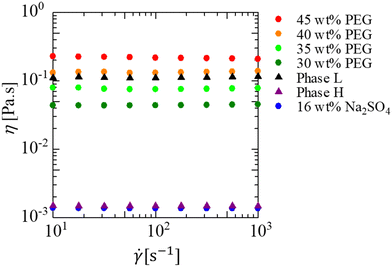
A partially miscible system is achieved at room temperature and atmospheric pressure in a system that consists of poly(ethylene glycol) 8000 (PEG, average molecular weight, Mw = 8000), Na2SO4, and water.52Fig. 1 shows the phase diagram of the solution used. In the present study, 30, 35, 40, and 45 wt% PEG solutions were used for the more viscous solution and a 16 wt% Na2SO4 solution was used for the less viscous solution. When the initial concentration at the interfacial region between the displacing and displaced liquids falls within the green region in Fig. 1, the system separates into two phases, indicating a partially miscible system. This is because the separation occurs with a finite solubility. In partially miscible systems, the phase separation of the spinodal decomposition type occurs during the fluid displacement. When the initial concentration at the interfacial region is within the blue region, the system exhibits a single phase. This implies a fully miscible system, as the fluids mix completely and form a single phase over time. We assume that the initial concentration at the interfacial region between the displacing and displaced liquids is half the concentration of the two liquids before being in contact with each other. For example, when the displaced liquid is 30 wt% PEG–70 wt% water, and the displacing liquid is 16 wt% Na2SO4–84 wt% water, the concentration of the mixture of the two liquids is 15 wt% PEG–8 wt% Na2SO4–77 wt% water (the bottom green point in Fig. 1). This composition is in the green region of Fig. 1 and, thus, the system is partially miscible. For the 35, 40, 45 wt% PEG solutions, the initial concentrations at the interfacial region are shown as other three green points. Therefore, all the prepared solution systems are partially miscible. This assumption is very simple, but we consider it to be appropriate. In a previous study,12 the same assumption was taken into consideration, and explained by the fact that the results of the fluid displacement, the calculation of free energy, and results of the interfacial tension measurement were all in good agreement. Notably, the more viscous PEG solutions are coloured with 0.1 wt% indigo carmine to visualise the displacement process. The indigo carmine does not dissolve in the Na2SO4 solution due to the salting-out effect. Therefore, we can track the interface between the PEG-rich and Na2SO4-rich solutions. Furthermore, the experiments and measurements for the viscosity and interfacial tension shown later are conducted using the solutions dyed with indigo carmine. Hence, we observe the dynamics including the dye in the present study. As the concentration of the Na2SO4 solution is maintained to be constant for all cases, the viscosity contrast depends on the PEG concentration. The viscosities of the solution used here are measured using a commercial rheometer (AR-G2) from TA-Instruments, Japan, with a cone plate. The viscosity results are shown in Fig. 2, where we measure the shear viscosity against the shear rate. We then found that all solutions are Newtonian because constant values are obtained at all shear rates.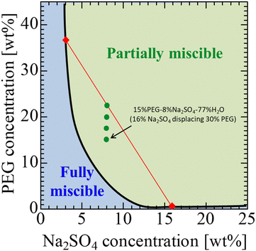 | ||
| Fig. 1 Phase diagram for a PEG–Na2SO4–H2O system.52 The solid curve shows the binodal curve. | ||
To compare partially miscible systems with immiscible systems, we prepared an immiscible fluid pair. This system consists of phases L and H. An aqueous solution composed of 22.5 wt% PEG and 8 wt% Na2SO4 (the top green point in Fig. 1) is separated into a PEG-rich phase (phase L, the lighter phase; top red diamond in Fig. 1) and a Na2SO4-rich phase (phase H, the heavier phase; bottom red diamond in Fig. 1). Phase L is dyed blue with 0.04 wt% indigo carmine. The solution system used here and the physical properties, such as viscosity and density, are summarized in Table 1.
| Displaced, more viscous solutions (viscosity [mPa s], density [g cm−3]) | Displacing, less viscous solutions (viscosity [mPa s], density [g cm−3]) |
|---|---|
| 45 wt% PEG solution (217, 1.08) | 16 wt% Na2SO4 solution (1.36, 1.15) |
| 40 wt% PEG solution (133, 1.07) | |
| 35 wt% PEG solution (76.6, 1.06) | |
| 30 wt% PEG solution (43.9, 1.05) | |
| Phase L (112, 1.06) | Phase H (1.48, 1.14) |
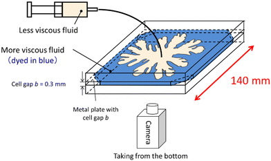
The displacement experiments of the more viscous PEG solutions with various concentrations of the less viscous Na2SO4 solution were conducted using Hele-Shaw cells with a gap of 0.3 mm, as shown in Fig. 3. First, we filled up the cell with the PEG solution, and then injected the Na2SO4 solution at 9.3 × 10⁻¹⁰ m3 s−1, controlled using a syringe pump. The displacement experiments were recorded from below the cell using a video camera.
3 Results and discussion
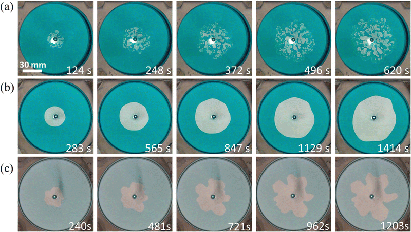
The VF experimental results are shown in Fig. 4. The 30 wt% and 35 wt% PEG cases show droplet formation, which is similar to the previous report.12 Conversely, the 40 wt% PEG case shows a wide fingering pattern. Interestingly, the 45 wt% PEG case shows a circular pattern, where the VF pattern is suppressed. A fingering pattern is obtained for the immiscible system consisting of phases L and H. The time evolution of the representative patterns is shown in Fig. 5. The droplet pattern (Fig. 5(a)) started immediately after the injection was started. Then, more droplets appeared from the center of the injection hole. Conversely, the circular pattern with the suppressed VF (Fig. 5(b)) maintained the circular shape all of the time. By contrast, the typical fingering pattern with phases L and H (Fig. 5(c)) began with a deformed circular shape at first, and then grew into a finger-like pattern. | ||
| Fig. 4 Patterns obtained by the displacement of a more viscous solution by a less viscous one. The time shown in the bottom right of each image is when the longest finger or droplet reaches 42 mm. | ||
The droplet pattern has been reported to be induced by the spinodal decomposition type of phase separation and the Korteweg force.12 As described by Mauri et al.13,53 and Poesio et al.,14 a force produced under spinodal decomposition is referred to as the Korteweg force. This is thermodynamically defined as the functional derivative of the free energy53 and is characterized by a body force. This force produces spontaneous convection to minimize the free energy stored at the interface;13–18,53 in addition, it has been reported that droplets can move spontaneously due to the Korteweg force.13–18 The first experimental study and numerical simulation of such droplet formation with a partially miscible VF pattern were reported by Suzuki et al.12 and Seya et al.,22 respectively. The mechanism of droplet formation clarified in each study is the same: their experimental system undergoes thermodynamic instability and phase separation of a spinodal type. In contrast to normal diffusion, such phase separation promotes mass transfer against the concentration gradients and enhances concentration fluctuations, leading to the separation of the system into low- and high-concentration regions. Furthermore, the body force generated by the chemical potential gradient creates a spontaneous convection, promoting phase separation.15,54 Thus, the growth of the deformed region due to hydrodynamic instabilities (viscous fingering) is enhanced by the thermodynamic instabilities (phase separation) when the less viscous solution is in contact with the more viscous solution in the spinodal region. Eventually, droplets are detached from the deformed region.
The circular pattern with suppressed VF in partially miscible systems has not been reported so far. First, we consider the mechanism from the viewpoint of a hydrodynamic effect, i.e., a viscosity contrast, which is the origin of the Saffman–Taylor instability. According to the study on the Saffman–Taylor instability in the radial geometry by Paterson,55 the most rapidly growing linearly unstable wavelength λm of an interface of radius r is
 | (2) |
Subsequently, we consider the mechanism from the viewpoint of the interfacial energy. The interfacial energy is related to the interfacial tension, and is defined as the first derivative of interfacial energy with respect to the interfacial area. We measure the interfacial tension because the interfacial energy is caused by a chemical thermodynamic effect related to the occurrence of the Korteweg force, as mentioned in the preceding paragraph. In the present study, the time evolution of the interfacial tension was measured with a spinning drop tensiometer56,57 (SITE100), from KRÜSS, Germany. In Fig. 6 we show the interfacial tension measured via the spinning method, which is denoted as γm, where the subscript “m” indicates “measured”. The previous report showed that the temporal increase in interfacial tension was evidence for the occurrence of the Korteweg force.12,19,20 In Fig. 6, a temporal increase in γm can be observed in the 30–40 wt% PEG cases, and the γm values are almost constant with time for the 45 wt% PEG case and the case with phases L and H. Therefore, the Korteweg force should occur in the 30–40 wt% PEG case. A constant γm against time is reasonable for the case of the L and H phases because the system is at equilibrium, implying that such a chemically thermodynamic effect cannot be induced. Although the γm value for the 45 wt% PEG case does not increase, we consider the temporary increase in genuine interfacial tension and show in the following paragraph that, in this case, the Korteweg force works to suppress the fingering pattern. The reason for the constant γm despite the temporal increase in the genuine interfacial tension will be discussed in the third to last paragraph of this section.
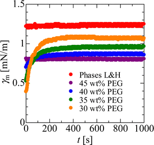 | ||
| Fig. 6 Time evolution of tmeasured interfacial tension, γm. The measurements are carried out under the conditions of 6000 rpm. | ||
In addition to the discussion about the interfacial energy, we can discuss another hydrodynamic effect, i.e., the absolute value of the interfacial tension. Based on eqn (2), it is understood that, as the interfacial tension increases under a given viscosity contrast, a more circular pattern is obtained. For this section we employ the interfacial tension measured at equilibrium because the magnitude relationship of the values does not change. From Fig. 6, the equilibrium γm values obtained are: γ30wt% = 1.07 mN m−1, γ35wt% = 0.960 mN m−1, γ40wt% = 0.867 mN m−1, γ35wt% = 0.802 mN m−1, γLH = 1.24 mN m−1, where the subscripts denote the respective PEG and L and H cases. The case of the equilibrium L and H phases shows the highest γm value of all. Therefore, the circular pattern observed with suppressed VF for the 45 wt% PEG case is not caused solely by the hydrodynamic effect of interfacial tension. The pattern with the suppressed VF is caused by a chemical thermodynamic effect.
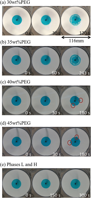
As discussed above, the pattern with suppressed VF should be caused by the Korteweg force. We now discuss the occurrence and direction of the force. In order to check the occurrence and direction of the Korteweg force, a static experiment was performed. We first filled the Hele-Shaw cell with the less viscous solution (16 wt% Na2SO4 solution or phase H) and then injected the more viscous solution (PEG solution of several concentrations or phase L) at a high-speed injection rate of 8.2 × 10⁻⁹ m3 s−1 to avoid occurrence of phase separation before our observation. In this experiment, therefore, no interfacial instability during the injection occurred because of the hydrodynamically stable situation, where the more viscous PEG solution (coloured in blue) displaces the less viscous Na2SO4 solution (colourless and transparent) in the Hele-Shaw cells. After the radius of the more viscous solution reached 20 mm, the injection was stopped, and we observed the behaviour of the pattern. We called this experiment the “stop experiment”. The results of the stop experiment are shown in Fig. 7, where the time evolution of the circular interface is displayed for each case. For the 30 and 35 wt% PEG cases, the droplets go into the coloured PEG solution, which indicates that the Korteweg force works from the Na2SO4 solution to the PEG solution. This direction is consistent with what was reported in previous studies.19 For the 40 and 45 wt% PEG cases, by contrast, the PEG solution moves outwards. Thus, the direction is opposite to that of the 30 and 35 wt% PEG cases. It is noted that the case of the L and H phases shows no change at the interface because the Korteweg force does not exist. As shown in Fig. 6, the interfacial tension changes during the first 200–300 seconds after the two solutions contact each other and reach saturation. The change in the interface behaviour shown in Fig. 7 corresponds to the change in interfacial tension in terms of the time scale. Namely, the deformation of the interface in all the systems except for the phases L and H system (Fig. 7(e)), started within t = 180 s. We observed that the deformation is not saturated over 300 s in the stop experiment. This is probably because the volume ratio of the PEG solution and the Na2SO4 solution is different between the stop experiment and the spinning drop measurement. We emphasize that the results of the stop experiment show direct experimental demonstration of the meaning of the Korteweg force because we can consider the meaning of the Korteweg force as the force generated during phase separation that causes convection. Therefore, the direction of the Korteweg force plays a key role in determining whether the resulting pattern is characterized by droplets or a suppressed viscous fingering pattern. The Korteweg force for a binary system of species A and B is expressed by:12,15,18,58,59
 | (3) |
![[small mu, Greek, tilde]](https://www.rsc.org/images/entities/i_char_e0e0.gif) = μA − μB is the chemical potential difference in the mixture, and ϕ is the molar fraction. Therefore, the direction of the force can be changed via the gradient of ϕ or
= μA − μB is the chemical potential difference in the mixture, and ϕ is the molar fraction. Therefore, the direction of the force can be changed via the gradient of ϕ or ![[small mu, Greek, tilde]](https://www.rsc.org/images/entities/i_char_e0e0.gif) . In the present study, we can change the sign of eqn (3) by changing the chemical potential gradient.
. In the present study, we can change the sign of eqn (3) by changing the chemical potential gradient.
In the VF experiments, the injection is directed from Na2SO4 to PEG. In the 30 and 35 wt% PEG cases, where the Korteweg force is directed from Na2SO4 to PEG, the direction of the injection and the Korteweg force are aligned, leading to an increased tendency for the fingertips to pinch-off. This promotes the formation of numerous droplets, as mentioned earlier (the second paragraph in this section). Conversely, in the 40 and 45 wt% PEG cases, where the Korteweg force is directed from PEG to Na2SO4, the injection and the Korteweg force directions are opposite, resulting in a stable interface that produces a circular pattern with suppressed viscous fingering. The explanation for this is described in the next paragraph.
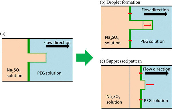
In the following paragraph, we will demonstrate that the stabilization of VF depends not only on the Korteweg force pointing from PEG to Na2SO4 but also on the interfacial region being thinner at the fingertip compared with the root of the finger. The schematic for the targeted VF is shown in Fig. 8, where the Na2SO4 solution is injected from left to right. When a finger grows (Fig. 8(a)), the interfacial width between the Na2SO4 and PEG solutions will become smaller at the fingertip than at its root, owing to larger convection at the fingertip. The Korteweg force is induced by a chemical potential gradient (∇μ = Δμ/δ: where Δμ is the chemical potential difference between the more and less viscous solutions and δ is the interface width).15,60 Therefore, the Korteweg force should be larger at the fingertip than at the root because the gradient is larger at the fingertip than at the root. When the Korteweg force is aligned with the flow, it primarily affects the fingertip and enhances the growth of the finger, as shown in Fig. 8(b). Note that, in this case, the finger becomes a droplet due to the nature of phase separation that leads to the pinching-off of the growing fingertip from the mother finger. When the Korteweg force works against the flow, it suppresses the growth of the finger since it works more significantly at the fingertip, as shown in Fig. 8(c).
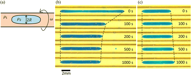
We here note the reason why the measured interfacial tension, γm, for the 45 wt% PEG case in the spinning drop tensiometer does not increase, although the Korteweg force works to suppress the fingering pattern. The method of the spinning drop tensiometer is first explained in Fig. 9(a). Vonnegut61 derived a well-known expression for simple calculation of the interfacial tension γ, namely:
One may consider the third dimension (gap) (z-direction) effects on the Hele-Shaw experiment from the interfacial constraint observed in the spinning drop experiments. Therefore, we mention here the third dimension (gap) effects on the Hele-Shaw experiment. In fully miscible systems, these effects have often been reported along with observation of the shade of the dye.62–66 Conversely, the effects are rarely discussed in immiscible systems, wherein almost no dye shading is observed. Similarly, in the present pattern with suppressed VF, no significant dye shading is observed. Therefore, we consider that third dimension (gap) effects are not observed in the pattern with suppressed VF. In addition, stabilization can be explained in the two-dimensional (xy direction) mode as described in Fig. 8. Based on this argument, we consider that the third dimension (gap) (z-direction) effects may not be crucial to the stabilization of VF in the partially miscible system.
Although the present study can contribute to the understanding of CO2-EOR (Enhanced Oil Recovery) because the situation under the ground is thermodynamically similar to this study, considerable research is required to improve the oil recovery efficiency and predict the amount of CO2 able to be injected into the reservoir as the effect of porosity and/or wettability on partially miscible VF patterns is still not clear from this study. Therefore, it will be interesting to incorporate these effects with our current experimental study in the future to fully understand the flow dynamics in partially miscible systems.
4 Conclusions
We experimentally demonstrate that the direction of the Korteweg force from a more viscous fluid to a less viscous fluid explains the circular pattern with suppressed VF in partially miscible systems as well as the mechanism for the suppression of VF. There have been many studies on VF suppression through hydrodynamic effects, such as changing the geometry, time-dependent gap strategies, time-dependent injection strategies and so on; however, the present study demonstrates the first experiment to suppress VF patterns using a chemical strategy in which we change the direction of the chemically thermodynamic Korteweg force. Therefore, the present study can provide new experimental findings on the coupling of interfacial phase separation and interfacial hydrodynamics. These findings will contribute directly to the higher efficiency of processes such as enhanced oil recovery26 and CO2 sequestration,27 where interfacial phase separation is considered to occur during the flow.Author contributions
K. Iwasaki: investigation, resources, data curation, validation. Y. Nagatsu: conceptualization, methodology, writing – review and editing. T. Ban: methodology, writing – review and editing. J. Iijima: data curation. M. Mishra: methodology, writing – review and editing. R. X. Suzuki: conceptualization, data curation, writing – original draft, writing – review and editing, funding acquisition, supervision, project administration.Conflicts of interest
There are no conflicts to declare.Acknowledgements
This study is supported by JSPS KAKENHI Grant No. 22K20402 and 22K03900, and JST Presto Grant No. JPMJPR22O5. The authors appreciate Mr Shoji Seya, Tokyo University of Agriculture and Technology, for his assistance in several experiments and fruitful discussions.References
- Y. Yeo, O. A. Basaran and K. Park, A new process for making reservoir-type microcapsules using ink-jet technology and interfacial phase separation, J. Controlled Release, 2003, 93, 161–173 CrossRef CAS PubMed.
- C. Snider, S. Y. Lee, Y. Yeo, G. J. Grégori, J. P. Robinson and K. Park, Microenvironment-controlled encapsulation (MiCE) process: Effects of PLGA concentration, flow rate, and collection method on microcapsule size and morphology, Pharm. Res., 2008, 25, 5–15 CrossRef CAS PubMed.
- I. Allijn, N. du Preez, M. Tasior, R. Bansal and D. Stamatialis, One-Step Fabrication of Porous Membrane-Based Scaffolds by Air-Water Interfacial Phase Separation: Opportunities for Engineered Tissues, Membranes, 2022, 12, 453 CrossRef CAS PubMed.
- S. Zhu, J. Forth, G. Xie, Y. Chao, J. Tian, T. P. Russell and H. C. Shum, Rapid Multilevel Compartmentalization of Stable All-Aqueous Blastosomes by Interfacial Aqueous-Phase Separation, ACS Nano, 2020, 14, 11215–11224 CrossRef CAS PubMed.
- P. G. Saffman and G. Taylor, The Penetration of a Fluid into a Porous Medium or Hele-Shaw Cell Containing a More Viscous Liquid, Proc. R. Soc. London, Ser. A, 1958, 245, 312–329 CAS.
- L. Rayleigh, Investigation of the Character of the Equilibrium of an Incompressible Heavy Fluid of Variable Density, Proc. London Math. Soc., 1882, 14, 170–179 CrossRef.
- D. J. Lewis, The Instability of Liquid Surfaces when Accelerated in a Direction Perpendicular to their Planes. II, Proc. R. Soc. London, Ser. A, 1950, 202, 81–96 CAS.
- J. S. Hong and M. C. Kim, Gravitational fingering and droplet formation during the phase separation of a partially miscible binary mixture in a vertical Hele-Shaw cell, Int. J. Heat Mass Transfer, 2023, 201, 123665 CrossRef CAS.
- G. M. Homsy, Viscous Fingering in Porous Media, Annu. Rev. Fluid Mech., 1987, 19, 271–311 CrossRef.
- X. Fu, L. Cueto-Felgueroso and R. Juanes, Viscous fingering with partially miscible fluids, Phys. Rev. Fluids, 2017, 2, 104001 CrossRef.
- M. A. Amooie, M. R. Soltanian and J. Moortgat, Hydrothermodynamic mixing of fluids across phases in porous media, Geophys. Res. Lett., 2017, 44, 3624–3634 CrossRef.
- R. X. Suzuki, Y. Nagatsu, M. Mishra and T. Ban, Phase separation effects on a partially miscible viscous fingering dynamics, J. Fluid Mech., 2020, 898, A11 CrossRef CAS.
- D. Molin, R. Mauri and V. Tricoli, Experimental evidence of the motion of a single out-of-equilibrium drop, Langmuir, 2007, 23, 7459–7461 CrossRef CAS PubMed.
- P. Poesio, G. P. Beretta and T. Thorsen, Dissolution of a liquid microdroplet in a nonideal liquid-liquid mixture far from thermodynamic equilibrium, Phys. Rev. Lett., 2009, 103, 064501 CrossRef PubMed.
- N. Vladimirova, A. Malagoli and R. Mauri, Diffusiophoresis of two-dimensional liquid droplets in a phase-separating system, Phys. Rev. E: Stat. Phys., Plasmas, Fluids, Relat. Interdiscip. Top., 1999, 60, 2037–2044 CrossRef CAS PubMed.
- T. Ban, A. Aoyama and T. Matsumoto, Self-generated Motion of Droplets Induced by Korteweg Force, Chem. Lett., 2010, 39, 1294–1296 CrossRef CAS.
- T. Ban, T. Yamada, A. Aoyama, Y. Takagi and Y. Okano, Composition-dependent shape changes of self-propelled droplets in a phase-separating system, Soft Matter, 2012, 8, 3908–3916 RSC.
- T. Ban, T. Fukuyama, S. Makino, E. Nawa and Y. Nagatsu, Self-Propelled Vesicles Induced by the Mixing of Two Polymeric Aqueous Solutions through a Vesicle Membrane Far from Equilibrium, Langmuir, 2016, 32, 2574–2581 CrossRef CAS PubMed.
- R. X. Suzuki, Y. Nagatsu, M. Mishra and T. Ban, Fingering pattern induced by spinodal decomposition in hydrodynamically stable displacement in a partially miscible system, Phys. Rev. Fluids, 2019, 4, 104005 CrossRef.
- R. X. Suzuki, R. Takeda, Y. Nagatsu, M. Mishra and T. Ban, Fluid Morphologies Governed by the Competition of Viscous Dissipation and Phase Separation in a Radial Hele-Shaw Flow, Coatings, 2020, 10, 960 CrossRef CAS.
- R. X. Suzuki, H. Tada, S. Hirano, T. Ban, M. Mishra, R. Takeda and Y. Nagatsu, Anomalous patterns of Saffman-Taylor fingering instability during a metastable phase separation, Phys. Chem. Chem. Phys., 2021, 23, 10926–10935 RSC.
- S. Seya, R. X. Suzuki, Y. Nagatsu, T. Ban and M. Mishra, Numerical study on topological change of viscous fingering induced by a phase separation with Korteweg force, J. Fluid Mech., 2022, 938, A18 CrossRef CAS.
- D. Truzzolillo, S. Mora, C. Dupas and L. Cipelletti, Off-equilibrium surface tension in colloidal suspensions, Phys. Rev. Lett., 2014, 112, 128303 CrossRef PubMed.
- J. E. Farrell and O. T. Valls, Spinodal decomposition in a two-dimensional fluid model, Phys. Rev. B: Condens. Matter Mater. Phys., 1989, 40, 7027–7039 CrossRef PubMed.
- T. Ban, T. Yamada, A. Aoyama, Y. Takagi and Y. Okano, Composition-dependent shape changes of self-propelled droplets in a phase-separating system, Soft Matter, 2012, 8, 3908–3916 RSC.
- L. W. Lake, R. T. Johns, W. R. Rossen and G. A. Pope, Fundamentals of Enhanced Oil Recovery, Society of petroleum engineers, Richardson, TX, 2014 Search PubMed.
- F. M. J. Orr and J. J. Taber, Use of Carbon Dioxide in Enhanced Oil Recovery, Science, 1984, 224, 563–569 CrossRef CAS PubMed.
- M. Rabaud, Y. Couder and N. Gerard, Dynamics and stability of anomalous Saffman-Taylor fingers, Phys. Rev. A: At., Mol., Opt. Phys., 1988, 37, 935–947 CrossRef PubMed.
- H. Thomé, M. Rabaud, V. Hakim and Y. Couder, The Saffman-Taylor instability: From the linear to the circular geometry, Phys. Fluids, 1989, 1, 224–240 CrossRef.
- T. T. Al-Housseiny, P. A. Tsai and H. A. Stone, Control of interfacial instabilities using flow geometry, Nat. Phys., 2012, 8, 747–750 Search PubMed.
- E. O. Dias and J. A. Miranda, Control of radial fingering patterns: A weakly nonlinear approach, Phys. Rev. E: Stat., Nonlinear, Soft Matter Phys., 2010, 81, 016312 CrossRef PubMed.
- Z. Zheng, H. Kim and H. A. Stone, Controlling viscous fingering using time-dependent strategies, Phys. Rev. Lett., 2015, 115, 174501 CrossRef PubMed.
- S. Li, J. S. Lowengrub, J. Fontana and P. Palffy-Muhoray, Control of viscous fingering patterns in a radial Hele-Shaw cell, Phys. Rev. Lett., 2009, 102, 174501 CrossRef PubMed.
- C. Y. Chen, C. W. Huang, L. C. Wang and J. A. Miranda, Controlling radial fingering patterns in miscible confined flows, Phys. Rev. E: Stat., Nonlinear, Soft Matter Phys., 2010, 82, 056308 CrossRef PubMed.
- E. O. Dias, E. Alvarez-Lacalle, M. S. Carvalho and J. A. Miranda, Minimization of viscous fluid fingering: A variational scheme for optimal flow rates, Phys. Rev. Lett., 2012, 109, 144502 CrossRef PubMed.
- D. Pihler-Puzovic, P. Illien, M. Heil and A. Juel, Suppression of complex fingerlike patterns at the interface between air and a viscous fluid by elastic membranes, Phys. Rev. Lett., 2012, 108, 074502 CrossRef CAS PubMed.
- D. Pihler-Puzović, R. Périllat, M. Russell, A. Juel and M. Heil, Modelling the suppression of viscous fingering in elastic-walled Hele-Shaw cells, J. Fluid Mech., 2013, 731, 162–183 CrossRef.
- D. Pihler-Puzović, G. G. Peng, J. R. Lister, M. Heil and A. Juel, Viscous fingering in a radial elastic-walled Hele-Shaw cell, J. Fluid Mech., 2018, 849, 163–191 CrossRef.
- B. Zhao, C. W. MacMinn and R. Juanes, Wettability control on multiphase flow in patterned microfluidics, Proc. Natl. Acad. Sci. U. S. A., 2016, 113, 10251–10256 CrossRef CAS PubMed.
- H. Tang, W. Grivas, D. Homentcovschi, J. Geer and T. Singler, Stability considerations associated with the meniscoid particle band at advancing interfaces in Hele-Shaw suspension flows, Phys. Rev. Lett., 2000, 85, 2112–2115 CrossRef CAS PubMed.
- A. Leshchiner, M. Thrasher, M. B. Mineev-Weinstein and H. L. Swinney, Harmonic moment dynamics in Laplacian growth, Phys. Rev. E: Stat., Nonlinear, Soft Matter Phys., 2010, 81, 016206 CrossRef PubMed.
- A. De Wit and G. M. Homsy, Viscous fingering in reaction-diffusion systems, J. Chem. Phys., 1999, 110, 8663–8675 CrossRef CAS.
- Y. Nagatsu, K. Matsuda, Y. Kato and Y. Tada, Experimental study on miscible viscous fingering involving viscosity changes induced by variations in chemical species concentrations due to chemical reactions, J. Fluid Mech., 2007, 571, 475–493 CrossRef CAS.
- Y. Nagatsu, S. K. Bae, Y. Kato and Y. Tada, Miscible viscous fingering with a chemical reaction involving precipitation, Phys. Rev. E: Stat., Nonlinear, Soft Matter Phys., 2008, 77, 067302 CrossRef PubMed.
- L. A. Riolfo, Y. Nagatsu, S. Iwata, R. Maes, P. M. J. Trevelyan and A. De Wit, Experimental evidence of reaction-driven miscible viscous fingering, Phys. Rev. E: Stat., Nonlinear, Soft Matter Phys., 2012, 85, 015304(R) CrossRef PubMed.
- A. De Wit, Chemo-hydrodynamic patterns in porous media, Philos. Trans. R. Soc., A, 2016, 374, 20150419 CrossRef PubMed.
- D. M. Escala, A. De Wit, J. Carballido-Landeira and A. P. Munuzuri, Viscous Fingering Induced by a pH-Sensitive Clock Reaction, Langmuir, 2019, 35, 4182–4188 CrossRef CAS PubMed.
- D. M. Escala, M. A. Budroni, J. Carballido-Landeira, A. De Wit and A. P. Muñuzuri, Self-organized traveling chemo-hydrodynamic fingers triggered by a chemical oscillator, J. Phys. Chem. Lett., 2014, 5, 413–418 CrossRef CAS PubMed.
- A. De Wit, Chemo-Hydrodynamic Patterns and Instabilities, Annu. Rev. Fluid Mech., 2020, 52, 531–555 CrossRef.
- D. M. Escala and A. P. Muñuzuri, A bottom-up approach to construct or deconstruct a fluid instability, Sci. Rep., 2021, 11, 24368 CrossRef CAS PubMed.
- Y. Nagatsu, A. Hayashi, M. Ban, Y. Kato and Y. Tada, Spiral pattern in a radial displacement involving a reaction-producing gel, Phys. Rev. E: Stat., Nonlinear, Soft Matter Phys., 2008, 78, 026307 CrossRef PubMed.
- S. M. Snyder, K. D. Cole and D. C. Sziag, Phase Compositions, Viscosities, and Densities for Aqueous Two-Phase Systems Composed of Polyethylene Glycol and Various Salts at 25 °C, J. Chem. Eng. Data, 1992, 37, 268–274 CrossRef CAS.
- D. Molin and R. Mauri, Enhanced heat transport during phase separation of liquid binary mixtures, Phys. Fluids, 2007, 19, 074102 CrossRef.
- P. C. Hohenberg and B. I. Halperin, Rev. Mod. Phys., 1977, 49, 435–479 CrossRef CAS.
- L. Paterson, Radial fingering in a Hele Shaw cell, J. Fluid Mech., 1981, 113, 513–529 CrossRef.
- J. A. Pojman, C. Whitmore, M. L. T. Liveri, R. Lombardo, J. Marszalek, R. Parker and B. Zoltowski, Evidence for the existence of an effective interfacial tension between miscible fluids: Isobutyric acid - Water and 1-butanol- water in a spinning-drop tensiometer, Langmuir, 2006, 22, 2569–2577 CrossRef CAS PubMed.
- B. Zoltowski, Y. Chekanov, J. Masere, J. A. Pojman and V. Volpert, Evidence for the Existence of an Effective Interfacial Tension between Miscible Fluids. 2. Dodecyl Acrylate-Poly(dodecyl acrylate) in a Spinning Drop Tensiometer, Langmuir, 2007, 23, 5522–5531 CrossRef CAS PubMed.
- D. Jasnow and J. Viñals, Coarse-grained description of thermo-capillary flow, Phys. Fluids, 1996, 8, 660–669 CrossRef CAS.
- N. Vladimirova, A. Malagoli and R. Mauri, Two-dimensional model of phase segregation in liquid binary mixtures, Phys. Rev. E: Stat. Phys., Plasmas, Fluids, Relat. Interdiscip. Top., 1999, 60, 6968–6977 CrossRef CAS PubMed.
- R. Mauri, R. Shinnar and G. Triantafyllou, Spinodal decomposition in binary mixtures, Phys. Rev. E: Stat. Phys., Plasmas, Fluids, Relat. Interdiscip. Top., 1996, 53, 2613–2623 CrossRef CAS PubMed.
- B. Vonnegut, Rotating bubble method for the determination of surface and interfacial tensions, Rev. Sci. Instrum., 1942, 13, 6–9 CrossRef CAS.
- Y. Nagatsu and T. Ueda, Effects of reactant concentrations on reactive miscible viscous fingering, AIChE J., 2001, 47, 1711–1720 CrossRef CAS.
- I. Bischofberger, R. Ramachandran and S. R. Nagel, Fingering versus stability in the limit of zero interfacial tension, Nat. Commun., 2014, 5, 5265 CrossRef CAS PubMed.
- P. Bunton, D. Marin, S. Stewart, E. Meiburg and A. De Wit, Schlieren imaging of viscous fingering in a horizontal Hele-Shaw cell, Exp. Fluids, 2016, 57, 28 CrossRef.
- P. Bunton, B. Dice, J. A. Pojman, A. De Wit and F. Brau, Reconstruction by fluorescence imaging of the spatio-temporal evolution of the viscosity field in Hele-Shaw flows, Phys. Fluids, 2014, 26, 114106 CrossRef.
- F. Haudin, L. A. Riolfo, B. Knaepen, G. M. Homsy and A. De Wit, Experimental study of a buoyancy-driven instability of a miscible horizontal displacement in a Hele-Shaw cell, Phys. Fluids, 2014, 26, 044102 CrossRef.
| This journal is © the Owner Societies 2023 |

