
 Open Access Article
 This Open Access Article is licensed under a Creative Commons Attribution-Non Commercial 3.0 Unported Licence
Tuning of the height of energy barrier between locally-excited and charge transfer states by altering the fusing position of o-carborane in phenylnaphthalene†
Junki
Ochi
 ,
Takumi
Yanagihara
,
Kazuo
Tanaka
* and
Yoshiki
Chujo
,
Takumi
Yanagihara
,
Kazuo
Tanaka
* and
Yoshiki
Chujo
Department of Polymer Chemistry, Graduate School of Engineering, Kyoto University Katsura, Nishikyo-ku, Kyoto 615-8510, Japan. E-mail: tanaka@poly.synchem.kyoto-u.ac.jp
First published on 17th April 2023
Abstract
We synthesized two types of the regioisomers fused by a phenylnaphthalene ring with variable connection points to the o-carborane scaffold. In this paper, we describe their photoluminescence (PL) properties and detailed photochemical mechanisms. According to the series of optical measurements, interestingly, they showed different PL characters in terms of wavelength and the dual-emission character despite that they have the common aromatic unit. Variable-temperature PL measurements and quantum chemical calculations suggested that the substitution position of aryl groups to o-carborane plays an important role in determining the energy barrier to the intramolecular charge-transfer (ICT) state at the S1 state. Finally, it is revealed that the relative position of the C–C bond of o-carborane and the aryl center should be responsible for the photophysical events of aryl-o-carboranes.
Introduction
Boron atoms can form various types of cluster compounds constructed by three-center two-electron bonds.1,2 Among them, o-carborane (1,2-dicarba-closo-dodecaborane) has been widely investigated as heat-resistant materials,3 medicinal reagents,4 and photoluminescent compounds5 because of its high stability and wide modifiability. One unique property of o-carborane is flexibility of the Ccage–Ccage distance (Ccage represents carbon in o-carborane) which can be varied in response to the external environment alteration. For example, it is theoretically and experimentally proved that electron-donating groups on the Ccage atom elongate the Ccage–Ccage distance by a back-donation effect.6,7 More drastically, o-carborane dianion possessing two cationic groups on the Ccage atom shows more than 1 Å longer Ccage–Ccage distance from the neutral one.8–10 Such a flexible character has recently been utilized as uranium capture/release switching triggered by a redox manipulation.11The flexible Ccage–Ccage character also plays a critical role in a photoluminescence (PL) process. In general, aryl-substituted o-carboranes form an intramolecular charge transfer (ICT) state at the S1 state, showing highly efficient solid-state emission.5 To date, many reports have described that those compounds show significant structural relaxation around the Ccage–Ccage bond after photoexcitation.12–21 Typically, quantum chemical calculations indicate that around 1.66 Å Ccage–Ccage distance at the S0 state is elongated to near 2.40 Å at the S1 state. This unique structural change inspired us to synthesize and investigate the Ccage–Bcage fused o-carboranes by a biphenyl skeleton.14 The ring-fused structure enabled a highly rigid structure except for the Ccage–Ccage bond, realizing the targeted investigation of the Ccage–Ccage elongation. Consequently, it was experimentally proved that fluorescence annihilation, observable in many aryl-o-carborane derivatives, should occur from the Ccage–Ccage relaxed structure for the first time. Like this, because the Ccage–Bcage fused structure has no rotatable substituent groups, it can reduce some factors involved in the S0–S1 (or S1–S0) transitions. This should be desirable for the deep investigation of a PL process of aryl-o-carboranes.
Recently, Lee and coworkers have investigated optical properties with o-carborane-substituted regioisomers of aromatic hydrocarbons such as fluorene,17 spirobifluorene,18,22 and pyrene.19 These reports clarified that the substitution position had a great effect on the ICT process, and different PL characters can be observed from regioisomers. The comparison with o-carborane-tethered anthracene isomers is another case; 1-(9-anthracenyl)-o-carborane23 showed bright ICT-rich emission (Φsolid: 38%), and 1-(2-anthracenyl)-o-carborane24 showed relatively weaker LE-rich emission (Φsolid: 8.8%). These results motivated us to investigate the relationship between the substitution position and optical properties in detail. Herein, we designed Ccage–Bcage fused isomers with the phenylnaphthalene ring (Fig. 1). The two isomers can be distinguished by the connecting position in the naphthalene ring: on the Ccage atom (CNaph) or the Bcage atom (Bnaph). Interestingly, optical properties were drastically varied between CNaph and BNaph despite fact that these molecules have the same chemical component as well as aromatic ring.
 | ||
| Fig. 1 The target two regioisomers obtained by a ring expansion of the previously reported carbon–boron fused o-carborane.14 | ||
Results and discussion
The phenylnaphthalene-fused o-carboranes CNaph and BNaph were synthesized as shown in Scheme 1. The construction of the o-carborane scaffold was achieved by the alkyne insertion reaction with decaborane(14), and the following Pd-catalyzed intramolecular coupling reaction afforded CNaph and BNaph. Structures of the products were confirmed by 1H, 13C{1H} and 11B NMR spectroscopy, high-resolution mass spectrometory measurements and single-crystal X-ray crystallography. | ||
| Scheme 1 Synthetic routes for CNaph and BNaph. | ||
From the single-crystal structural data, the ring fusing positions in CNaph and BNaph were confirmed (Fig. 2). In both compounds, the main intermolecular interaction was found to be a CcageH⋯π interaction as often observed in many o-carborane derivatives.14,25 The geometrical differences between the two isomers affected the relative arrangement of molecules; BNaph formed a dimer structure by mutual CcageH⋯π interactions, and CNaph showed unilateral CcageH⋯π interactions. Considering the fact that other intermolecular interactions such as a π⋯π interaction were hardly observed, the CcageH⋯π interaction plays a significant role in determining the crystal structures.
 | ||
| Fig. 2 Single-crystal structures of CNaph and BNaph (left) and CcageH⋯π interactions in CNaph and BNaph (right). | ||
UV-vis absorption spectra in CHCl3 solutions were almost identical between CNaph and BNaph. The longest wavelength absorption band around 319 nm can be attributed to the π–π* transition at the phenylnaphthalene ring (Fig. 3). This fact indicates that the connecting position of the naphthalene unit has electronically little effect in the ground state. The absorption maxima of CNaph and BNaph were observed in the longer wavelength region than that of biphenyl-fused o-carborane (277 nm),14,26 implying the extension of π-conjugation by the additional benzene ring.
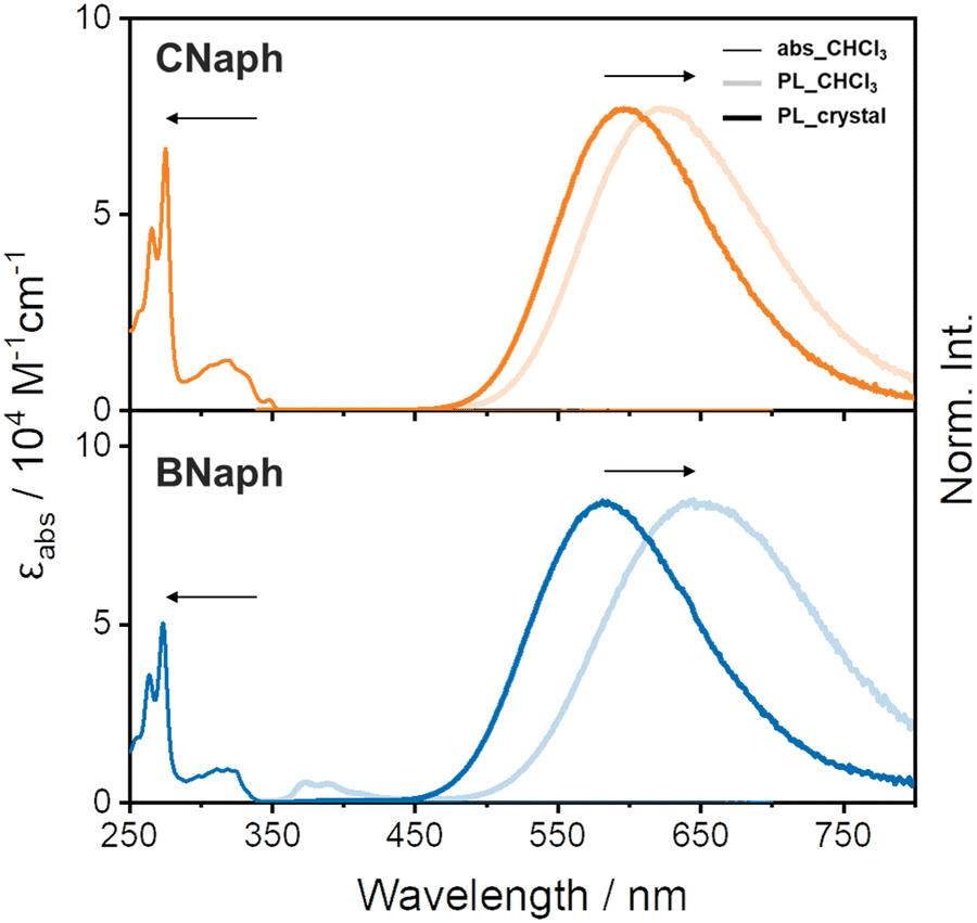 | ||
| Fig. 3 Absorption (abs) and PL spectra of CNaph (top) and BNaph (bottom). | ||
In PL spectra, both CNaph and BNaph showed a broad structureless band around 600 nm (Fig. 3). To attribute the emission mechanism, the shift of the PL bands by changing the solvent polarity was examined. Accordingly, the peak positions were shifted to the longer wavelength region by increasing solvent polarity although the absorption peaks were inert to solvent (Fig. S1 and S2, ESI†). These results clearly indicate that the PL bands should be attributed to the ICT emission. Moreover, the ICT bands from the crystalline samples (598 nm for CNaph and 583 nm for BNaph) showed a hypsochromic shift comparing to those from the solution ones, even in non-polar methylcyclohexane solvent (599 nm for CNaph and 601 nm for BNaph). According to many reports from aryl-o-carboranes and our previous work in which the same trend was observed, it was revealed that this spectral shift should be originated from the suppression of Ccage–Ccage elongation in the o-carborane unit in crystal.14 Since structural relaxation in the excited state should be restricted in the condensed state, luminescence should be obtained from incompletely-stabilized structures. Finally, emission bands in the shorter wavelength region can be observed. Additionally, the fluorescence quantum yield was enhanced by crystallization in both compounds, indicating that these compounds have the AIE character (Table 1).5 It is because ACQ can be avoided by suppressing intermolecular interactions owing to o-carborane.
Quantum chemical calculations for the isolated molecules supported the CT character (Fig. 4). In the ground state, both the highest occupied molecular orbitals (HOMOs) and the lowest unoccupied molecular orbitals (LUMOs) were on the aromatic moiety. This is the typical behavior of the locally-excited (LE) transition observed in the absorption spectra where the peak position was insensitive in solvent polarity. In contrast, LUMOs were localized mainly on the o-carborane unit in the S1 excited state, indicating that o-carborane works as an electron-acceptor to form the ICT state. In addition, the correlation between the PL wavelength and the Ccage–Ccage elongation at the S1 state was investigated (Table 2). In the case of the isolated molecule, the Ccage–Ccage length increased by about 0.7 Å from the S0 to the S1 state. On the other hand, the degree of Ccage–Ccage elongation was restricted by the surrounding molecules when the molecular coordinates of the single-crystal structure were extracted and treated by the QM/MM model (see Experimental section for detail). Although QM/MM results did not realize the qualitative tendency between CNaph and BNaph, the mechanism on the hypsochromic shift of emission bands in crystal from solution could be justified (Fig. 3). In summary, optical measurements and quantum chemical calculations showed a good correlation.
 | ||
| Fig. 4 Frontier orbitals of CNaph and BNaph in both S0 and S1 states. H and L represent HOMO and LUMO, respectively. | ||
| Compound | One molecule | Crystal | ||||
|---|---|---|---|---|---|---|
| Calcd. | Calcd. | Exp. | Calcd. | Calcd. | Exp. | |
| Ccage–Ccage | PL | PL | Ccage–Ccage | PL | PL | |
| a Measured in CHCl3 (1.0 × 10⁻⁵ M). b Estimated by QM/MM analyses. | ||||||
| CNaph | S0![[thin space (1/6-em)]](https://www.rsc.org/images/entities/char_2009.gif) :1.65 Å :1.65 Å |
587 nm (ICT) | 625 nm (ICT)a | S1:2.31 Åb |
485 nmb | 598 nm |
| S1:2.43 Å |
||||||
| BNaph | S0:1.63 Å |
343 nm (LE) | 374 nm (LE)a | S1:2.29 Åb |
504 nmb | 583 nm |
| S1(LE):1.65 Å |
561 nm (ICT) | 651 nm (ICT)a | ||||
| S1(ICT):2.35 Å |
||||||
Although there were some similarities in the two regioisomers as shown above, it is notable that only BNaph in the solution state possessed the dual emission properties. Since the peak position of the emission band at around 374 nm was not influenced by solvent polarity, this band is attributable to LE emission (Fig. S2, ESI†). In contrast, the emssion band in the longer wavelength region is attributable to ICT emission because of the solvatochromic behavior (Fig. S2, ESI†). To gain insight on the difference in the LE/ICT balance, PL measurements in frozen glass matrices in methylcyclohexane (1.0 × 10⁻⁵ M) at 77 K were conducted (Fig. S3, ESI†). The LE emission band of BNaph became dominant at 77 K under the frozen condition in contrast to the ICT-rich spectra at room temperature. This result implies that there should be a significant energy barrier between the LE and ICT states.15,23,27–29 On the other hand, the PL spectrum of CNaph was still dominated by ICT emission even in the frozen state, suggesting that a faint LE-ICT energy barrier should exist. These data represent that the regioisomeric ring fusing position has little effect on the electronic state of the ground state, while that has a drastic effect on the relaxation process in the excited state. On the basis of these results, the lower fluorescence quantum yield of BNaph than CNaph (Table 1) can be partially explained by quenching from the LE state as a trapping site. However, some aryl-o-carboranes possessing little LE/ICT barrier30 also showed moderate ΦPL values, suggesting there should be an additional factor relating to nonradiative decay from the ICT state to comprehend the overall PL process.20
Next, temperature-dependent PL spectra in CHCl3 were collected for further investigation of the excited state (Fig. 5a). CNaph consistently exhibited only the ICT emission band, confirming the barrierless character between the LE and ICT states. The PL intensity got lower at higher temperature probably because the nonradiative decay process should be accelerated. In contrast, dual-emissive BNaph showed a gradual change in the LE/ICT balance. The PL spectra normalized at the LE region demonstrated the increase in the ICT emission ratio in the higher temperature region, corresponding to the assumption that there should be the significant LE/ICT energy barrier in the structural relaxation process in the excited state. Motivated by these results, we prepared the Stevens–Ban plot of BNaph (Fig. 5b).31 Generally, this plot can be divided into two regions. If the LE and ICT states are in thermal equilibrium, a positive slope is obtained as eqn (1):
 | (1) |
 | (2) |
 | (3) |
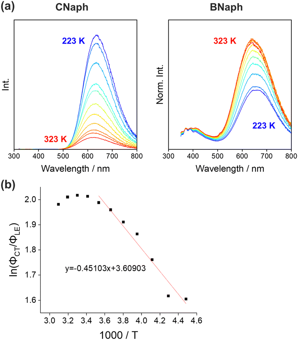 | ||
| Fig. 5 (a) PL spectra of CNaph and BNaph in 1.0 × 10⁻⁵ M CHCl3 solution measured at 223–323 K in steps of 10 K. (b) Stevens–Ban plot of BNaph in CHCl3 solution and the fitting line. | ||
The difference in the energy barrier between CNaph and BNaph was reproduced by a quantum chemical calculation. We optimized the molecular structures both at the S0 and S1 states with fixing the Ccage–Ccage distance in steps of 0.1 Å. The obtained energies were plotted, indicating that only BNaph had the energy barrier in the S1 state between the Franck–Condon structure and the global minimum structure (Fig. 6 and Fig. S6, ESI†). Although the scanned curve along Ccage–Ccage distance does not necessarily represent the actual relaxation pathway, the estimated Ea value 8.77 kJ mol−1 can be interpreted as an upper limit. This value is higher than the experimentally-obtained lower limit (3.75 kJ mol−1), suggesting the true energy barrier should be between them. In addition, the plot clarified that the longer PL wavelength from BNaph than CNaph is due to the instability in S0 energy at the S1-optimized structure in BNaph.
 | ||
| Fig. 6 Energy levels at the S0 and S1 states of CNaph (orange) and BNaph (blue) with variable Ccage–Ccage distance. | ||
Finally, the difference in dual-emission character is verified by considering ICT efficiency. In the ICT systems, it is generally known that the effective distance between donor and acceptor units is an important factor in determining ICT efficiency.32 Considering the electron-accepting character of o-carborane via the Ccage–Ccage region and the electron-donating character of the aryl group, the relative position of the Ccage–Ccage bond and the aryl center should be critical for determining the LE/ICT balance of o-carboranes.33 On the basis of this idea, we prepared the Lippert–Mataga plot to estimate the differences in the dipole moments (Δμ) between the ground and excited states (Fig. S4, ESI†). Consequently, a greater Δμ value was obtained from BNaph (12.06 debye) than CNaph (8.41 debye). The more significant PL quenching of BNaph than CNaph in polar solvents (Fig. S2, ESI†) can also be attributed to the larger Δμ value of BNaph. Moreover, the natural transition orbitals (NTOs) are also consistent with the larger effective ICT distance of BNaph than CNaph (Fig. S5, ESI†). First, the distribution of electron is mainly on o-carborane and partially on the benzene ring connected to the Ccage atom in both compounds. On the other hand, the hole is distributed over a whole molecule, and the contribution of the o-carborane moiety is larger in CNaph than BNaph, probably because of the effective electronic communication between o-carborane and naphthalene than o-carborane and benzene.34 Consequently, the effective distance in ICT of CNaph should get shorter than that of BNaph. These results support the experimental and computational data that showed smaller ICT efficiency in BNaph.
Conclusion
On the basis of the detailed investigation of the two phenylnaphthalene ring-fused regioisomers CNaph and BNaph, it is demonstrated that the substitution position of the aryl group in o-carborane plays a critical role in regulating the energy barrier between LE and ICT states. In particular, the temperature dependency of LE/ICT balance, the potential energy curves obtained by DFT calculation, NTO analysis, and the estimated Δμ values from the Lippert–Mataga plot totally supported the weakened ICT efficiency in BNaph. In other words, the height of the energy barrier and the dual-emission character were proved to be successfully tuned by modulating the positional relation between o-carborane and the aryl substituent. We believe our findings could be of significance for establishing the rational molecular design for constructing not only o-carborane-based emitters but also stimuli-responsive luminochromic materials.Conflicts of interest
There are no conflicts to declare.Acknowledgements
This work was partially supported by the Toyo Gosei Memorial Foundation and JSPS KAKENHI Grant Numbers JP21H02001 and JP21K19002 (for K.T) and JP21J14940 (for J.O).References
- R. N. Grimes, Carboranes, Elsevier, 2011 Search PubMed.
- W. N. Lipscomb, Science, 1977, 196, 1047–1055 CrossRef CAS PubMed.
- J. Sun, M. Gao, L. Zhao, Y. Zhao, T. Li, K. Chen, X. Hu, L. He, Q. Huang, M. Liu and Y. Song, React. Funct. Polym., 2022, 173, 105213 CrossRef CAS.
- P. Stockmann, M. Gozzi, R. Kuhnert, M. B. Sárosi and E. Hey-Hawkins, Chem. Soc. Rev., 2019, 48, 3497–3512 RSC.
- J. Ochi, K. Tanaka and Y. Chujo, Angew. Chem., Int. Ed., 2020, 59, 9841–9855 ( Angew. Chem. , 2020 , 132 , 9925–9939 ) CrossRef CAS PubMed.
- J. M. Oliva, N. L. Allan, P. v R. Schleyer, C. Viñas and F. Teixidor, J. Am. Chem. Soc., 2005, 127, 13538–13547 CrossRef CAS PubMed.
- J. Li, R. Pang, Z. Li, G. Lai, X. Xiao and T. Müller, Angew. Chem., Int. Ed., 2019, 58, 1397–1401 ( Angew. Chem. , 2019 , 131 , 1411–1415 ) CrossRef CAS PubMed.
- J. P. H. Charmant, M. F. Haddow, R. Mistry, N. C. Norman, A. G. Orpen and P. G. Pringle, Dalton Trans., 2008, 1409 RSC.
- J. Schulz, A. Kreienbrink, P. Coburger, B. Schwarze, T. Grell, P. Lönnecke and E. Hey-Hawkins, Chem. – Eur. J., 2018, 24, 6208–6216 CrossRef CAS PubMed.
- G. B. Gange, A. L. Humphries, D. E. Royzman, M. D. Smith and D. V. Peryshkov, J. Am. Chem. Soc., 2021, 143, 10842–10846 CrossRef CAS PubMed.
- M. Keener, C. Hunt, T. G. Carroll, V. Kampel, R. Dobrovetsky, T. W. Hayton and G. Ménard, Nature, 2020, 577, 652–655 CrossRef CAS PubMed.
- K. Yuhara, K. Tanaka and Y. Chujo, Mater. Chem. Front., 2022, 6, 1414–1420 RSC.
- J. Ochi, K. Yuhara, K. Tanaka and Y. Chujo, Chem. – Eur. J., 2022, 28, e202200155 CrossRef CAS PubMed.
- J. Ochi, K. Tanaka and Y. Chujo, Dalton Trans., 2021, 50, 1025–1033 RSC.
- K. Nishino, K. Tanaka and Y. Chujo, Asian J. Org. Chem., 2019, 8, 2228–2232 CrossRef CAS.
- M. Kim, C. H. Ryu, D. K. You, J. H. Hong and K. M. Lee, ACS Omega, 2022, 7, 24027–24039 CrossRef CAS PubMed.
- D. K. You, H. So, C. H. Ryu, M. Kim and K. M. Lee, Chem. Sci., 2021, 12, 8411–8423 RSC.
- S. Kim, J. H. Lee, H. So, J. Ryu, J. Lee, H. Hwang, Y. Kim, M. H. Park and K. M. Lee, Chem. – Eur. J., 2020, 26, 548–557 CrossRef CAS PubMed.
- S. Kim, J. H. Lee, H. So, M. Kim, M. S. Mun, H. Hwang, M. H. Park and K. M. Lee, Inorg. Chem. Front., 2020, 7, 2949–2959 RSC.
- D. Tahaoğlu, H. Usta and F. Alkan, J. Phys. Chem. A, 2022, 126, 4199–4210 CrossRef PubMed.
- L. Ji, S. Riese, A. Schmiedel, M. Holzapfel, M. Fest, J. Nitsch, B. F. E. Curchod, A. Friedrich, L. Wu, H. H. Al Mamari, S. Hammer, J. Pflaum, M. A. Fox, D. J. Tozer, M. Finze, C. Lambert and T. B. Marder, Chem. Sci., 2022, 13, 5205–5219 RSC.
- S. Kim, H. So, J. H. Lee, H. Hwang, H. Kwon, M. H. Park and K. M. Lee, Molecules, 2019, 24, 4135 CrossRef CAS PubMed.
- H. Naito, K. Nishino, Y. Morisaki, K. Tanaka and Y. Chujo, Angew. Chem., Int. Ed., 2017, 56, 254–259 ( Angew. Chem. , 2017 , 129 , 260–265 ) CrossRef CAS PubMed.
- X. Wu, J. Guo, Y. Cao, J. Zhao, W. Jia, Y. Chen and D. Jia, Chem. Sci., 2018, 9, 5270–5277 RSC.
- R. J. Blanch, M. Williams, G. D. Fallon, M. G. Gardiner, R. Kaddour and C. L. Raston, Angew. Chem., Int. Ed. Engl., 1997, 36, 504–506 CrossRef CAS.
- Y. Morisaki, M. Tominaga, T. Ochiai and Y. Chujo, Chem. – Asian J., 2014, 9, 1247–1251 CrossRef CAS PubMed.
- K. Wada, K. Hashimoto, J. Ochi, K. Tanaka and Y. Chujo, Aggregate, 2021, 2, e93 CAS.
- H. Mori, K. Nishino, K. Wada, Y. Morisaki, K. Tanaka and Y. Chujo, Mater. Chem. Front., 2018, 2, 573–579 RSC.
- K. Nishino, H. Yamamoto, K. Tanaka and Y. Chujo, Org. Lett., 2016, 18, 4064–4067 CrossRef CAS PubMed.
- H. Naito, K. Nishino, Y. Morisaki, K. Tanaka and Y. Chujo, J. Mater. Chem. C, 2017, 5, 10047–10054 RSC.
- U. Leinhos, W. Kuehnle and K. A. Zachariasse, J. Phys. Chem., 1991, 95, 2013–2021 CrossRef CAS.
- V. Balzani, Electron Transfer in Chemistry, WILEY, vol. 1, 2001 Search PubMed.
- K.-R. Wee, W.-S. Han, D. W. Cho, S. Kwon, C. Pac and S. O. Kang, Angew. Chem., Int. Ed., 2012, 51, 2677–2680 ( Angew. Chem. , 2012 , 124 , 2731–2734 ) CrossRef CAS PubMed.
- H. Naito, K. Nishino, Y. Morisaki, K. Tanaka and Y. Chujo, Chem. – Asian J., 2017, 12, 2134–2138 CrossRef CAS PubMed.
Footnote |
| † Electronic supplementary information (ESI) available. CCDC 2236202 and 2236203. For ESI and crystallographic data in CIF or other electronic format see DOI: https://doi.org/10.1039/d3cp00334e |
| This journal is © the Owner Societies 2023 |