
 Open Access Article
 This Open Access Article is licensed under a
 Creative Commons Attribution 3.0 Unported Licence
Computational and experimental studies of the wide bandgap semiconductors NH4TiOF3 and (NH4)2TiOF4†
Bingyu
Lei
 a,
Lisette
Warren
a,
Carole
Morrison
a,
Gwilherm
Kerherve
b,
William S. J.
Skinner
b,
David J.
Payne
c and
Neil
Robertson
*a
a,
Lisette
Warren
a,
Carole
Morrison
a,
Gwilherm
Kerherve
b,
William S. J.
Skinner
b,
David J.
Payne
c and
Neil
Robertson
*a
aSchool of Chemistry, The University of Edinburgh, David Brewster Road, Edinburgh EH9 3FJ, UK. E-mail: Neil.Robertson@ed.ac.uk
bDepartment of Materials, Imperial College London, Exhibition Road, London, SW7 2AZ, UK
cResearch Complex at Harwell, Harwell Science and Innovation Campus, Didcot, Oxfordshire OX11![[thin space (1/6-em)]](https://www.rsc.org/images/entities/char_2009.gif) 0FA, UK
0FA, UK
First published on 16th January 2023
Abstract
As the topotactic synthetic precursor of the ubiquitous functional semiconductor anatase TiO2, ammonium fluoroxotitanates, such as NH4TiOF3 and (NH4)2TiOF4, have received lots of research interest as synthetic precursors. However, few of the existing studies focus on their properties and possible applications on their own. To fill this gap, both NH4TiOF3 and (NH4)2TiOF4 were studied in this work experimentally by material characterization and computationally via DFT calculations. Electronic structures of both materials from experimental and computational perspectives were mutually supportive. Based on these, immobilised NH4TiOF3 was preliminarily tested as a UV photocatalyst for dye degradation. Reasonable photocatalytic activities were observed.
Introduction
Mesocrystals have aroused widespread research interest because of their balanced properties from the nanocrystalline building blocks and the overall collective functions.1,2 Among the synthetic semiconductor mesocrystals, TiO2 mesocrystals have attracted a large share of attention due to the wide applicability of porous TiO2 semiconductors and the unique properties brought to their applications.3 Two main strategies have been developed for the synthesis of semiconductor mesocrystals, including the assembly of pre-formed nano building blocks from bottom to top, or the conversion from crystallographically similar precursors from top down. The latter is also called topotactic transformation, from which the mesocrystalline products always inherit the overall size and the morphology from the precursor materials.4 So the unique design features of the precursor can be incorporated into the product material and provide more possibilities for the morphologies and structures of the product. In the case of TiO2, ammonium oxofluorotitanates, NH4TiOF3 and (NH4)2TiOF4, are the most adopted precursors due to their crystallographic similarity to anatase TiO2.4,5 For these reasons, the understanding of NH4TiOF3 and (NH4)2TiOF4 is important to the design and preparation of functional TiO2 mesocrystals.The studies on ammonium oxofluorotitanates were started by Patarin et al. and Laptash et al., who determined the crystal structure of (NH4)2TiOF4 (monoclinic P21/m, 1994) and NH4TiOF3 (orthorhombic Pnma, 1999) respectively.6,7 The existing studies on ammonium oxofluorotitanates have focused mainly on the crystal structure, thermal behaviour and their conversion to more well-known TiO2.8–10 Other properties and applications of both materials are less studied. Recently, some groups have explored the possibility of applying NH4TiOF3 to different areas such as lithium storage and photocatalysis.11,12 In those examples however, NH4TiOF3 was part of a composite along with other materials, such as NH4TiOF3/TiO2/g-C3N4 and NH4TiOF3/TiO2. The direct use of NH4TiOF3 and (NH4)2TiOF4 is still unexplored to the best of our knowledge.
In this work, we aim to provide some initial inspiration for further studies and applications of NH4TiOF3 and (NH4)2TiOF4. Both materials were characterized by Powder X-ray diffraction (PXRD), Ultraviolet-Visible diffuse reflectance spectroscopy (UV-Vis DRS) and X-ray photoelectron spectroscopy (XPS). The band structure, density of states (DOS) and crystal orbital Hamiltonian populations (COHP) have also been studied by DFT calculations in order to discuss the electronic structures of both materials and the relation to their crystal structures. As a preliminary attempt, immobilised NH4TiOF3 was applied as a UV photocatalyst due to its similar band gap to TiO2. Although not better than the immobilised benchmark TiO2 P25, a reasonable photocatalytic activity was observed for the immobilised NH4TiOF3.
Experimental
Preparation of NH4TiOF3, (NH4)2TiOF4 and TiO2
Powder form NH4TiOF3 was prepared according to the recipe described in previous work.13 Briefly, (NH4)2TiF6 (acros organics) aqueous solution was mixed with ammonia solution with the final concentration ratio as 4:3. After stirring the solution for 5 min and letting it stand for 6 h at room temperature, the precipitate was collected by centrifugation and washed sequentially with water and ethanol, and dried in ambient conditions. (NH4)2TiOF4 was firstly prepared as immobilised films following the procedure developed in our recent work.14 Specifically, a piece of FTO substrate (1.5 × 2 cm) was immersed in 4 mL aqueous solution containing 0.6 M (NH4)2TiF6 and 1 M (NH4)O2CCH3. After 24 hours reaction at room temperature, the substrate with coated materials were taken out, rinsed with water and ethanol and dried with hot air. Powder form (NH4)2TiOF4 samples were then obtained by scratching from the immobilised (NH4)2TiOF4 films. Powder form TiO2 for XPS studies was prepared by sintering the NH4TiOF3 in a pre-heated furnace at 800 °C for 15 min.15
To prepare immobilised NH4TiOF3 for photocatalysis reactions, immobilised (NH4)2TiOF4 was first prepared on a sanded glass substrate (1 cm × 3 cm) following the procedure for FTO substrate (vide supra). However the concentration of (NH4)2TiF6 was 0.5 M. Immobilised NH4TiOF3 was then obtained by sintering the immobilised (NH4)2TiOF4 to 250 °C with a heating rate of 2 °C min−1.
To prepare immobilised P25 for photocatalysis reaction, a printable paste was doctor-bladed on a sanded glass substrate, followed by sintering at 500 °C for 30 min. The P25 paste was prepared according to a reported analogous method.16 Specifically, 0.16 g P25 was mixed with 0.65 g anhydrous terpineol solvent, 0.45 g EC-10 stock solution (ethyl cellulose, 10 cP, 10 wt% in ethanol), 0.35 g EC-30 stock solution (ethyl cellulose, 30–70 cP, 10 wt% in ethanol) and 0.8 mL anhydrous ethanol. After stirring overnight, the mixture was sonicated for 2 min and stirred at 13500 rpm for 1 min using an ultra-terrax mixer for 3 cycles and dried by rotary-evaporation at 40 °C.
Material characterization
PXRD was carried out on a Bruker D2 PHASER using Cu Kα radiation. UV-Vis DRS were carried out using a JASCO V-670 UV/Vis/NIR spectrophotometer equipped with a 60 mm ϕ integrating sphere accessory. BaSO4 was used as the reference. XPS spectra were acquired using a high-throughput Thermo Fisher K-alpha spectrometer with a monochromatic Al Kα micro-focused X-ray source.Solid state calculations
The calculations were performed using the CRYSTAL17 code.17,18 Triple zeta valence basis sets were utilised for all atoms (Ti, O: m-def2-tzvp; N, F, H: pob-tzvp-rev2), built from Gaussian-type functions, developed for solid-state applications.19 Hybrid functional HSE06 was selected due to its robust record in accurately calculating lattice parameters and electronic band gaps.20,21 Other functionals including pure GGA PBE22 and hybrid functional B3LYP23,24 were also implemented for single-point energy calculation as comparison. The Grimme D3 dispersion correction scheme (DFT-D3) has been adopted for all calculations of NH4TiOF3 and (NH4)2TiOF4.25 Convergence of the k-point grid was considered for energy differences of 10−6 Hartree, resulting in a Monkhorst–Pack shrinking factor26 of 10 for all the calculations. The input geometries of NH4TiOF3 and (NH4)2TiOF4 for the solid-state calculations were taken from published crystal structure data (NH4TiOF3: CCDC-1880514;27 (NH4)2TiOF4: ICSD-75405)6 which were collected at room temperature. Geometry optimisation was applied to the full structure (crystal lattice and atomic positions) with convergence reached when the energy threshold between two successive optimisation steps was below 10−7. Band structures, DOS and COHP were computed both as a single-point energy calculation (fixed unit cell and atomic positions) and also via the geometry optimisation. Anatase TiO2 (ICSD-154601)28 was also tested by single-point energy calculation for comparison. Absolute values of the valence band top and the conduction band bottom for three materials from single-point energy calculations were used to plot their simplified band structure diagram.Photocatalysis test
Films on sanded glass slides were scratched to obtain 1 cm × 2.4 cm patterns before testing. The film samples or bare substrate were submerged into 3 mL of the dye solution in a quartz cuvette. The concentration of each dye used, namely Rhodamine B (RhB) and Methylene Blue (MB), was 1 × 10⁻⁵ M and 3 × 10⁻⁵ M respectively. The solution with the tested film sample was stirred in the dark for several minutes (30 min for RhB, 1 h for MB) to establish an adsorption equilibrium and then irradiated with a LED (365 nm, 3W, Intelligent LED Solutions) which was placed at a distance of 5 cm from the cuvette. The UV-Vis absorption of the dye solution was measured in situ at an interval of 15 min using a JASCO V670 UV/Vis/NIR spectrophotometer. The scan parameter was set to be 250–800 nm with a 400 nm min−1 speed.Results and discussion
Material characterization
XRD results of the powder form NH4TiOF3 and (NH4)2TiOF4 are shown in Fig. 1. Both materials show a good match with the PDF card from the database respectively. The optical behaviour was characterized by UV-Vis DRS. Tauc plots of both materials are also shown in Fig. 1. The choice of the index n for the (αhν)1/n, which indicates the nature of the electron transition (direct or indirect), was based on the DFT calculation results (vide infra). Accordingly, direct band gaps of ∼3.56 eV and ∼3.98 eV were extracted for NH4TiOF3 and (NH4)2TiOF4, respectively. Both are wider than anatase TiO2, which has a typical indirect band gap of ∼3.2 eV.29 | ||
| Fig. 1 XRD patterns and Tauc plots of powder form (a) and (b) NH4TiOF3 and (c) and (d) (NH4)2TiOF4. | ||
Both NH4TiOF3 and (NH4)2TiOF4 were also studied by XPS and compared with TiO2 which was prepared by sintering NH4TiOF3 at 800 °C for 15 min. The phase check of the TiO2 was carried out by XRD with the result shown in Fig. S1 (ESI†), indicating a pure phase of anatase. The XPS survey spectra are shown in Fig. S2 (ESI†). For all samples, Ti and O were detected with a small amount of C, which possibly arose from the adventitious hydrocarbon from the XPS instrument itself. In addition, strong peaks associated with F and N were also observed for NH4TiOF3 and (NH4)2TiOF4, consistent with the composition of both materials.
High-resolution XPS spectra are shown in Fig. S3 (ESI†). Both NH4TiOF3 and (NH4)2TiOF4 exhibit dominant N 1s peaks at ∼402 eV, which corresponds to the NH4+ in both structures.30 There is a small peak at ∼400 eV for NH4TiOF3, possibly coming from N species adsorbed on the surface.31 F 1s spectra for both materials can be deconvoluted into two peaks at ∼685 eV and ∼686 eV respectively, close to the values observed for Ti–F and O–Ti–F in other work.32 The TiO2 prepared from NH4TiOF3 shows a weak signal at ∼684 eV, which is likely due to the doping of trace amounts of F− on the surface.33 The O 1s spectra for all samples can be fitted with three peaks, including the main peak ascribed to the O in the lattice and the other two possibly assigned to different oxygen species at the surface.34 In Ti 2p spectra, NH4TiOF3 and (NH4)2TiOF4 exhibit wider Ti 2p3/2 peaks at higher binding energy than TiO2 because of the contribution from Ti–F. A low intensity deconvoluted peak at lower binding energy for all the samples is possibly from a trace amount of Ti3+.35 Compared with TiO2, a shift of O 1s peaks and Ti 2p peaks to higher energy can be observed for both NH4TiOF3 and (NH4)2TiOF4. Comparing their structures, the substitution of some O by F in TiO6 octahedra could be a possible explanation.
Fig. 2 displays the valence band XPS spectra of NH4TiOF3, (NH4)2TiOF4 and the comparison TiO2. Compared with anatase TiO2, NH4TiOF3 and (NH4)2TiOF4 exhibit a shift of ∼0.72 eV and ∼1.19 eV of the valence band onset respectively, indicating their probably deeper valence band maximum than anatase TiO2.
 | ||
| Fig. 2 XPS valence band spectra of NH4TiOF3, (NH4)2TiOF4 and TiO2. | ||
Structures of NH4TiOF3 and (NH4)2TiOF4
According to the published crystal data, the room temperature structure of NH4TiOF3 belongs to the orthorhombic space group Pca21, with crystal lattice parameters as follows: a = 7.5526(1), b = 6.3051(1), c = 7.5845(1) Å. The 40 atom cell of NH4TiOF3 is illustrated in Fig. 3(a). It was described by Boytsova et al. as a layered structure composed of corner-sharing TiO2F4 octahedra stabilized and sandwiched by (NH4)+ tetrahedra along the b-direction.27 However, it is worth noting that in other works based on the crystal structure defined by Laptash, this direction was defined as [001].7 In this work, we use the definition of Boytsova. O atoms were positioned in the ab-plane rather than apical, which is supported by the experimental observation that during thermal hydrolysis of NH4TiOF3, the linking of octahedral layers produces TiOF2 as a possible intermediate phase and then anatase TiO2.27,36 (NH4)2TiOF4 is isostructural with β-(NH4)2FeF5 and consists of kinked parallel chains of TiO2F4 octahedra connected by the two trans-oxygens as shown in Fig. 3(b). The monoclinic P21/m space group and lattice parameters (a = 6.3245(1), b = 7.5422(1), c = 11.0095(2) Å) were reported by Patarin et al. in 1994.6 In a similar way, the thermal hydrolysis of (NH4)2TiOF4 to NH4TiOF3 and then anatase TiO2 also supports the position of the oxygens. | ||
| Fig. 3 Structures of (a) NH4TiOF3 and (b) (NH4)2TiOF4. Colour scheme: grey (Ti), red (O), green (F), blue (N), white (H). | ||
Structural optimisation of NH4TiOF3 and (NH4)2TiOF4
Geometry optimisation was applied to both NH4TiOF3 and (NH4)2TiOF4 using hybrid functional HSE06-D3 considering its recorded accuracy in calculating crystal lattice parameters.37 In the full geometry optimisation, both the lattice parameters and atomic coordinates are changed to minimise the total energy of the system. This effectively models the material at zero Kelvin, hence the optimised structure is not expected to be the same as the room-temperature experimental structure.The optimised parameters of NH4TiOF3 are compared with the experimental data (Table 1), which are the same as that after the single-point energy calculation. HSE06-D3 gave a very close similarity to the experimental a and c lattice parameters for NH4TiOF3 with relative differences below 0.67% and a slightly reduced b parameter by 2.85%. The cell volume was decreased by 3.02%. More differences were obtained by comparing the bond lengths (Table S1, ESI†) and bond angles (Table S2, ESI†) before and after the optimisation. As also visualised in Fig. S4 (ESI†), Ti atoms are more off-centred in the TiO2F4 octahedra after the geometry optimisation. This could be the result of the second order Jahn–Teller effect, which favours a reduced symmetry to optimize Ti–O bonding at the ground state.39,40 The variance of the bond angles Ti–F–Ti and Ti–O–Ti also implies octahedral tilting after the geometry optimisation.
| Single-point calculation | Geometry optimisation | |
|---|---|---|
| a | 7.55 | 7.50 |
| b | 6.31 | 6.13 |
| c | 7.58 | 7.62 |
| α | 90 | 90 |
| β | 90 | 90 |
| γ | 90 | 90 |
| Volume | 361.2 | 350.3 |
| Band gap | 3.72 | 5.60 |
| E Fermi/ToV | −6.31 | −7.75 |
| BoC | −2.59 | −2.15 |
For (NH4)2TiOF4, after the geometry optimisation, parameter c was similar to the results from the single-point calculation, i.e. the experimental data, whereas a and b were decreased by around 1.8% and 3.5% respectively, leading to a decreased volume of 5.7% (Table 2). The changes in bond lengths and bond angles are listed in Tables S3 and S4 (ESI†) respectively with the label of atoms given in Fig. S5 (ESI†). No Ti displacement can be observed. However, the bond length of Ti–O decreased after the optimisation and most of the Ti–F bond lengths increased. The octahedra were also distorted by tilting along the Ti–O–Ti direction.
| Single-point calculation | Geometry optimisation | |
|---|---|---|
| a | 6.32 | 6.21 |
| b | 7.54 | 7.28 |
| c | 11 | 10.9 |
| α | 90 | 90 |
| β | 90.12 | 90.13 |
| γ | 90 | 90 |
| Volume | 525.2 | 495 |
| Band gap | 4.46 | 4.99 |
| E Fermi/ToV | −6.58 | −7.34 |
| BoC | −2.12 | −2.34 |
Both NH4TiOF3 and (NH4)2TiOF4 exhibited differences between their room-temperature structures and optimised structures in the ground state. Hence their electronic properties in different states are also expected to be different, for example, the conduction band bottom, the valence band top and their corresponding atomic contribution. Electronic property studies for both materials were applied to both states. However, more focus was put on the room-temperature structure via the single-point energy calculation so that the results can be compared with that from room-temperature characterisation. The details are shown in the next sections.
Electronic properties of NH4TiOF3
The band structure and projected density of states (PDOS) of NH4TiOF3 were first calculated based on the single-point calculation using HSE06-D3 functional (Fig. 4). Direct band gap values of 3.72 eV were obtained with both the top of the valence band (VB) and the bottom of the conduction band (CB) located at the Γ point (labelled as G in band structure figures, the same hereinafter). Other functionals including PBE-D3 and B3LYP-D3 were also tested with the results given in Fig. S6 (ESI†). Generally, all three functionals provided qualitatively similar form of plots in terms of the band dispersion and atom contribution. Different band gaps were obtained from PBE-D3 (2.39 eV) and B3LYP-D3 (3.89 eV) respectively. Among the tested functionals, HSE06-D3 gives the closest band gap to the experimental value obtained by UV-Vis DRS (3.56 eV, Fig. 1(b)). This agrees with previous studies that have shown that HSE06 is very good at computing electronic band gaps.37,38 Further analysis was done by projecting the PDOS onto orbitals (Fig. 5) and performing COHP analysis (Fig. 6). For COHP, the band structure is partitioned against the Hamiltonian population for a specified interaction, where anti-bonding interactions are positive, bonding interactions are negative and non-bonding states go to zero. Accordingly, the CB is mainly composed of the 3d states of Ti with Ti–F and Ti–O anti-bonding character and non-bonding character for both at the very bottom of the CB, while most of the VB is O p-states with non-bonding character in respect to Ti and some Ti–O bonding/Ti–F anti-bonding at the very top of the VB. The lowest CB state is dispersionless along the X–S, Y–Γ, U–R and T–Z directions, indicating more difficult conducting along these directions. These Brillouin zone directions (illustrated in Fig. S7, ESI†) with more flat bands correspond to the [010] direction of NH4TiOF3, along which layers of (TiOF3)− octahedra are sandwiched by (NH4)+ tetrahedra.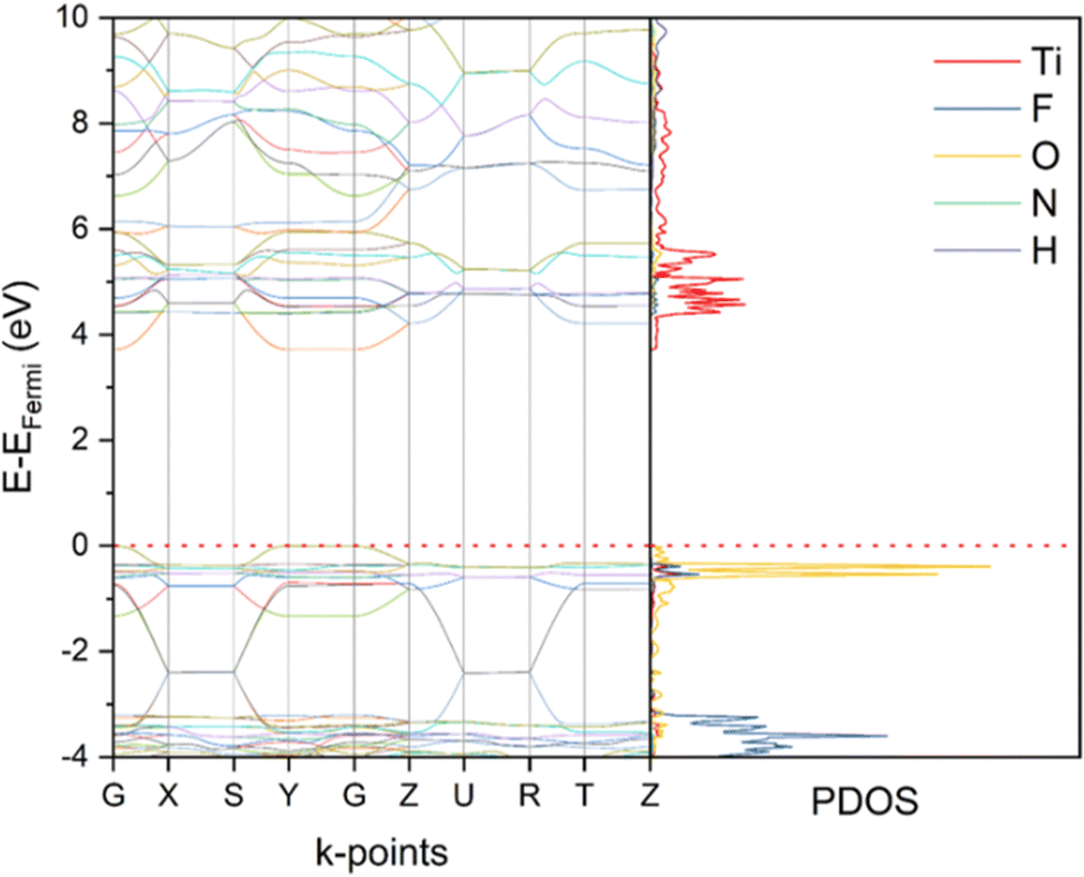 | ||
| Fig. 4 Computed band structures and corresponding PDOS of NH4TiOF3 using HSE06-D3 functionals after the single-point energy calculation. EFermi = −6.31 eV. | ||
 | ||
| Fig. 5 Computed density of states of NH4TiOF3 over each orbital, computed using HSE06-D3 functional. | ||
 | ||
| Fig. 6 COHP of NH4TiOF3 over Ti–O (red line) and Ti–F (blue line) bonds, computed based on single-point energy calculation using HSE06-D3 functional. A positive COHP value (negative in –COHP plot) represents anti-bonding interactions, while a negative COHP (positive in –COHP plot) denotes bonding interactions. | ||
Fig. S8 (ESI†) shows the computed band structure and PDOS based on the ground state structure after the geometry optimisation. Generally, the band structure and composition are similar to that based on the experimental structure after the single-point calculation. However, an enlarged band gap was obtained (5.60 eV vs. 3.72 eV, Table 1), and the variance is mainly from the top of the VB position (−7.75 eV vs. −6.31 eV, Table 1). The comparison of COHP (Fig. S9, ESI†) indicates that at the ground state, the VB of NH4TiOF3 contains more Ti–O anti-bonding character compared with the single-point energy calculation result. Comparing the geometry of the experimental data and after the geometry optimisation, octahedral distortion including the octahedral tilting and metal cation off-centre displacement is likely to be the main reason.41 Similar to other work, the effect is mainly on the overlap of orbitals.42,43
Electronic properties of (NH4)2TiOF4
The band structure of (NH4)2TiOF4 were also investigated based on the single-point energy calculations. The result with hybrid-functional HSE06-D3 is shown in Fig. 7 and those based on PBE-D3 and B3LYP-D3 are shown in Fig. S10 (ESI†). The K-point path in the first Brillouin zone is illustrated in Fig. S11 (ESI†). As we have observed for NH4TiOF3, all the functionals resulted in similar band structure and composition but different value of the band gap. Indirect band gaps of 2.98 eV, 4.64 eV and 4.46 eV were obtained from PBE-D3, B3LYP-D3 and HSE06-D3 respectively. The bottom of CB was found to locate at the Γ point while the maximum of VB was at the A point. However, the energy variance between the Γ point and A point at either the top of the VB or the bottom of the CB is negligible according to the computed band structures. So the band gap of (NH4)2TiOF4 can be practically treated as direct. Comparing with the direct optical band gap obtained from UV-Vis DRS (3.98 eV, Fig. 1(d)), HSE06-D3 also gave the most accurate estimation among all the functionals, and therefore was also used for further analysis of (NH4)2TiOF4. | ||
| Fig. 7 Computed band structures and corresponding PDOS of (NH4)2TiOF4 using HSE06-D3 functional after the single-point energy calculation. EFermi = −6.58 eV. | ||
According to results of PDOS over orbitals (Fig. 8) and COHP (Fig. 9), the CB of (NH4)2TiOF4 is mainly composed of the 3d states of Ti and 2p states of F with anti-bonding character, while the VB mainly originates from O 2p states, which are bonding with respect to Ti 3d states. The band dispersion is mainly observed along the Γ–Z, D–B, A–E and C2–Y2 directions, but more flat along other directions. As previously discussed, this anisotropy is closely related to the crystallochemical anisotropy. In the case of (NH4)2TiOF4, the strongest band dispersion is observed along the directions corresponding to the [010] direction, parallel to the chains of TiO2F4 octahedra.
 | ||
| Fig. 8 Computed density of states of (NH4)2TiOF4 over each orbital, computed using HSE06-D3 functional. | ||
 | ||
| Fig. 9 COHP of (NH4)2TiOF4 over Ti–O (red line) and Ti–F (blue line) bonds, computed based on single-point energy calculation using HSE06-D3 functional. | ||
The band structure, PDOS, COHP were also calculated after the geometry optimisation of (NH4)2TiOF4. Results are shown in Fig. S12 and S13 (ESI†). Similar to the observation for NH4TiOF3, the band structure and composition at the ground state is similar to that based on the experimental structure after the single-point calculation and the main difference comes from the band gap and specifically the top of the VB. However, the band gap variance in the case of (NH4)2TiOF4 is smaller than that of NH4TiOF3 (0.53 eV vs. 1.88 eV), consistent with less change in the geometry after the geometry optimisation and the resulting lower effect on the overlap of orbitals.
Comparison with anatase TiO2
Anatase TiO2 was also studied as a comparison. Single-point energy calculation was carried out using hybrid functional HSE06-D3 which performed the best for both NH4TiOF3 and (NH4)2TiOF4. The band gap was obtained as 3.49 eV, which is also close to the optical band gap of anatase TiO2 (∼3.2 eV).29 The corresponding band structure and PDOS are shown in Fig. 10 with the k-point path illustrated in Fig. S14 (ESI†). | ||
| Fig. 10 Computed band structures and PDOS of anatase using HSE06-D3 functional after the single-point energy calculation. EFermi = −6.09 eV. | ||
Based on the single-point energy calculation results for NH4TiOF3, (NH4)2TiOF4 and anatase using HSE06-D3 functional, a simplified diagram of their band structures can be drawn as Fig. 11. Compared with anatase, both NH4TiOF3 and (NH4)2TiOF4 have larger band gaps, which indicates their absorption of deep UV light. This is in good agreement with the UV-Vis DRS results. In addition, (NH4)2TiOF4 and NH4TiOF3 have successively deeper valence band than anatase, in line with the observation in the XPS valence band studies. However, comparing the band dispersion of NH4TiOF3 and (NH4)2TiOF4 with anatase (Fig. 4, 7 and 10), the layered structure of NH4TiOF3 and the chain structure of (NH4)2TiOF4 may limit the electron mobility in certain directions of both materials, demonstrated by the very flat valence and conduction bands near the band gap for these materials.
 | ||
| Fig. 11 A simplified band structure diagram of anatase TiO2, NH4TiOF3 and (NH4)2TiOF4. The top of the valence band (VB) and bottom of the conduction band (CB) values are taken from the single-point calculation results using HSE06-D3 functional. | ||
Photocatalysis tests
According to the observation in our previous work, sintering the immobilised (NH4)2TiOF4 to 250 °C can produce immobilised NH4TiOF3 consisting of nano-sized building blocks.14 This may provide a higher surface area of immobilised NH4TiOF3 than the direct synthesis on the substrates. Due to the similar positioning of the band gap between NH4TiOF3 and antase TiO2 from DFT calculations and the experimental UV-Vis DRS spectra, it is reasonable to check the photocatalytic performance of immobilised NH4TiOF3 under UV irradiation.As a proof of concept, an immobilised NH4TiOF3 sample converted from the immobilised (NH4)2TiOF4 was tested as photocatalyst in the photodegradation of RhB and MB. The XRD patterns of the as-prepared immobilised NH4TiOF3 and the sample after photodegradation reaction of RhB are provided in Fig. S15 (ESI†). No impurities can be observed before or after the photocatalysis reaction. Photocatalysis test results are shown in Fig. 12 and the 1st order rate constants were calculated and listed in Table S5 (ESI†). The immobilised benchmark TiO2 P25 has been demonstrated to be an excellent UV photocatalyst and has been widely studied accordingly.44 It is therefore unlikely that the immobilised NH4TiOF3 would exceed the performance of P25. Despite this however, NH4TiOF3 shows the ability to degrade organic dyes under UV irradiation with rate performance around half that of P25. In addition, the high adsorption of cationic dye MB (Table S6, ESI†) suggests a negatively charged surface of the immobilised NH4TiOF3 in water under the test conditions. However, to further understand the surface properties of NH4TiOF3, further experimental analyses and computational modelling are required.
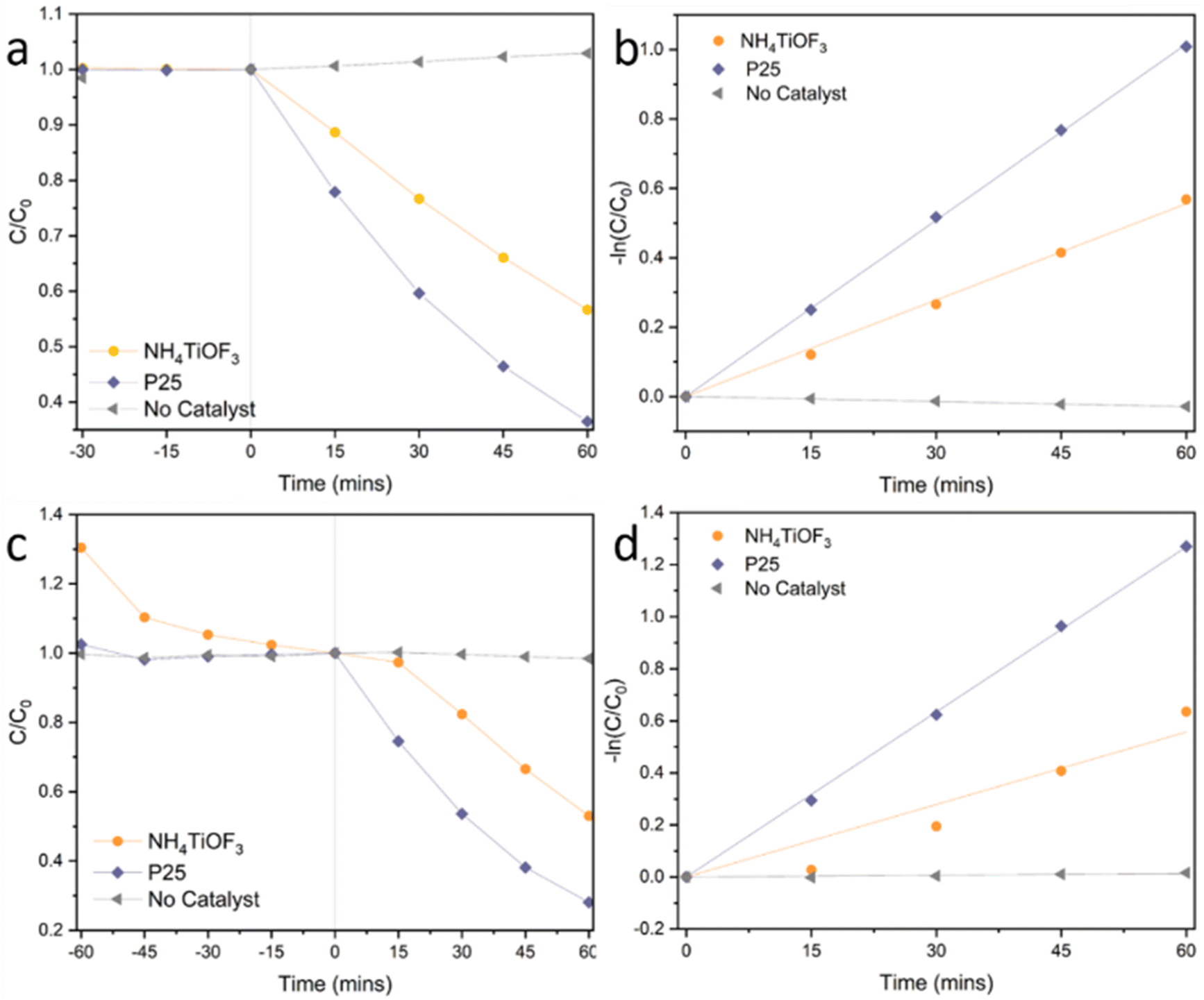 | ||
| Fig. 12 Photodegradation of (a) and (b) RhB and (c) and (d) MB by immobilised NH4TiOF3, compared with immobilised P25 and no catalyst. C is the concentration of the dye at different time point, while C0 is the concentration at the light-on point. | ||
The poorer photocatalytic activity of the immobilised NH4TiOF3 may be explained from different aspects. First, the commonly used UV light source gives peak intensity at 365 nm, which doesn’t match ideally with the adsorption spectrum of NH4TiOF3. In addition, the layered structure of NH4TiOF3 results in a poor electron mobility along certain crystalline direction and thus potentially inefficient charge transport from the bulk to the active sites at the surface. Inspired from this attempt, further improvement may be achieved by using a deeper UV light source, constructing appropriate orientation of NH4TiOF3 crystals to improve the overall electron mobility or doping with other elements to adjust the optical band gap.
Conclusions
DFT calculations have been applied to NH4TiOF3 and (NH4)2TiOF4 to study their electronic structure and properties. The results were compared with experimental characterizations including UV-Vis DRS and XPS using anatase as a comparison. Performing geometry optimisation on NH4TiOF3 and (NH4)2TiOF4 resulted in enlarged band gaps observed for both materials, which was associated with the distortion of TiO2F4 octahedra. From the single-point energy calculations, the hybrid HSE06 functional provided excellent agreement with the band gaps and valence band positions with respect to the experimental results. Compared with anatase TiO2, both NH4TiOF3 and (NH4)2TiOF4 have wider band gaps and deeper valence bands, which indicates the application of both materials to areas that require deep UV response. The direct or pseudo-direct band gaps also point towards application in optoelectronic areas. According to these experimental and computational results, a preliminary attempt was also made to use immobilised NH4TiOF3 as a photocatalyst for the degradation of organic dyes. A reasonable photocatalytic activity was observed and further improvement is believed to be possible by constructing appropriate orientation of NH4TiOF3 crystals or doping with other elements. Collectively, this work may inspire future work that can exploit in applications the specific semiconductor properties of NH4TiOF3 and (NH4)2TiOF4.Conflicts of interest
There are no conflicts to declare.Acknowledgements
B. Lei gratefully acknowledges China Scholarship Council and The University of Edinburgh for a PhD scholarship.Notes and references
- M. G. Ma and H. Cölfen, Curr. Opin. Colloid Interface Sci., 2014, 19, 56–65 CrossRef CAS.
- L. Zhou and P. Obrien, J. Phys. Chem. Lett., 2012, 3, 620–628 CrossRef CAS PubMed.
- B. Zhang, S. Cao, M. Du, X. Ye, Y. Wang and J. Ye, Catalysis, 2019, 9, 91 Search PubMed.
- L. Zhou, D. Smyth-Boyle and P. O’Brien, J. Am. Chem. Soc., 2008, 130, 1309–1320 CrossRef CAS PubMed.
- B. Lei, Y. Guo, H. Xie, J. Chen, X. Li, Y. Wu and L. Zhou, Cryst. Growth Des., 2019, 19, 5460–5465 CrossRef CAS.
- J. Patarin, F. Marcuccilli-Hoffner, H. Kessler and P. Daniels, Eur. J. Solid State Inorg. Chem., 1994, 31, 501–511 CAS.
- N. M. Laptash, I. G. Maslennikova and T. A. Kaidalova, J. Fluorine Chem., 1999, 99, 133–137 CrossRef CAS.
- O. Boytsova, I. Dovgaliuk, D. Chernyshov, A. Eliseev, P. O’Brien, A. J. Sutherland and A. Bosak, J. Appl. Crystallogr., 2019, 52, 23–26 CrossRef CAS.
- Y. Liu, Y. Zhang, H. Li and J. Wang, Cryst. Growth Des., 2012, 12, 2625–2633 CrossRef CAS.
- N. M. Laptash, E. B. Merkulov and I. G. Maslennikova, J. Therm. Anal. Calorim., 2004, 63, 197–204 CrossRef.
- B. Lv, L. Lu, X. Feng, X. Wu, X. Wang, X. Zou and F. Zhang, Ceram. Int., 2020, 46, 26689–26697 CrossRef CAS.
- Y. Liu, N. Jiang, J. Chen, X. Wang, H. Pan, H. Zhang, W. Zhang, Z. Wang, S. Luo, G. Huang and H. Sun, ACS Appl. Mater. Interfaces, 2020, 12, 20404–20413 CrossRef CAS PubMed.
- B. Lei, A. Valluvar Oli, A. Ivaturi and N. Robertson, Sustainable Energy Fuels, 2022, 6, 502–511 RSC.
- B. Lei and N. Robertson, Sol. RRL, 2023, 7(1), 2200831, DOI:10.1002/solr.202200831.
- Y. Guo, H. Li, J. Chen, X. Wu and L. Zhou, J. Mater. Chem. A, 2014, 2, 19589–19593 RSC.
- S. Ito, T. N. Murakami, P. Comte, P. Liska, C. Grätzel, M. K. Nazeeruddin and M. Grätzel, Thin Solid Films, 2008, 516, 4613–4619 CrossRef CAS.
- R. Dovesi, V. Saunders, C. Roetti, R. Orlando, C. M. Zicovich-Wilson, F. Pascale, B. Civalleri, K. Doll, N. Harrison, I. Bush, M. Llunel, M. Causà, Y. Noël, L. Maschio, A. Erba, M. Rérat and S. Casassa, CRYSTAL17 User's Manual, 2018.
- B. K. R. Dovesi, A. Erba, R. Orlando, C. M. Zicovich-Wilson, B. Civalleri, L. Maschio, M. Rerat, S. Casassa, J. Baima and S. Salustro.
- M. F. Peintinger, D. V. Oliveira and T. Bredow, J. Comput. Chem., 2013, 34, 451–459 CrossRef CAS PubMed.
- J. Heyd, G. E. Scuseria and M. Ernzerhof, J. Chem. Phys., 2003, 118, 8207 CrossRef CAS.
- P. Borlido, J. Schmidt, A. W. Huran, F. Tran, M. A. L. Marques and S. Botti, npj Comput. Mater., 2020, 6, 1–17 CrossRef.
- J. P. Perdew, K. Burke and M. Ernzerhof, Phys. Rev. Lett., 1996, 77, 3865 CrossRef CAS PubMed.
- A. D. Becke, J. Chem. Phys., 1993, 98, 5648 CrossRef CAS.
- C. Lee, W. Yang and R. G. Parr, Phys. Rev. B: Condens. Matter Mater. Phys., 1988, 37, 785 CrossRef CAS PubMed.
- S. Grimme, J. Antony, S. Ehrlich and H. Krieg, J. Chem. Phys., 2010, 132, 154104 CrossRef PubMed.
- H. J. Monkhorst and J. D. Pack, Phys. Rev. B: Solid State, 1976, 13, 5188 CrossRef.
- O. Boytsova, I. Dovgaliuk, D. Chernyshov, A. Eliseev, P. O’Brien, A. J. Sutherland and A. Bosak, J. Appl. Crystallogr., 2019, 52, 23–26 CrossRef CAS.
- I. Djerdj and A. M. Tonejc, J. Alloys Compd., 2006, 413, 159–174 CrossRef CAS.
- J. Zhang, P. Zhou, J. Liu and J. Yu, Phys. Chem. Chem. Phys., 2014, 16, 20382–20386 RSC.
- J. Han, M. Zarrabeitia, A. Mariani, M. Kuenzel, A. Mullaliu, A. Varzi, S. Passerini, J. Han, M. Zarrabeitia, A. Mariani, M. Kuenzel, A. Mullaliu, A. Varzi and S. Passerini, Adv. Mater., 2022, 34, 2201877 CrossRef CAS PubMed.
- H. Ozaki, N. Fujimoto, S. Iwamoto and M. Inoue, Appl. Catal., B, 2007, 70, 431–436 CrossRef CAS.
- L. Å. Näslund and I. Persson, Appl. Surf. Sci., 2022, 593, 153442 CrossRef.
- J. C. Yu, J. Yu, W. Ho, Z. Jiang and L. Zhang, Chem. Mater., 2002, 14, 3808–3816 CrossRef CAS.
- H. Sun, Y. Bai, W. Jin and N. Xu, Sol. Energy Mater. Sol. Cells, 2008, 92, 76–83 CrossRef CAS.
- P. Zhang, T. Tachikawa, M. Fujitsuka and T. Majima, ChemSusChem, 2016, 9, 617–623 CrossRef CAS PubMed.
- L. Zhou, D. Smyth Boyle and P. O’Brien, Chem. Commun., 2006, 144–146 Search PubMed.
- H. Benjamin, J. G. Richardson, S. A. Moggach, S. Afanasjevs, L. Warren, M. R. Warren, D. R. Allan, C. A. Morrison, K. V. Kamenev and N. Robertson, Phys. Chem. Chem. Phys., 2020, 22, 6677–6689 RSC.
- L. R. Warren, E. McGowan, M. Renton, C. A. Morrison and N. P. Funnell, Chem. Sci., 2021, 12, 12711–12718 RSC.
- Y. Liu, A. Kumar, Z. Fan, Y. Zhang, Q. Ke, K. Zeng, J. Wang, D. J. Singh and K. P. Ong, Appl. Phys. Lett., 2013, 102, 232903 CrossRef.
- R. G. Pearson and K. Eo-Ek, Proc. Natl. Acad. Sci. U. S. A., 1975, 72, 2104–2106 CrossRef CAS PubMed.
- F. Wang, I. Grinberg and A. M. Rappe, Appl. Phys. Lett., 2014, 104, 152903 CrossRef.
- R. Prasanna, A. Gold-Parker, T. Leijtens, B. Conings, A. Babayigit, H. G. Boyen, M. F. Toney and M. D. McGehee, J. Am. Chem. Soc., 2017, 139, 11117–11124 CrossRef CAS PubMed.
- I. Levin, E. Cockayne, V. Krayzman, J. C. Woicik, S. Lee and C. A. Randall, Phys. Rev. B: Condens. Matter Mater. Phys., 2011, 83, 094122 CrossRef.
- M. E. Simonsen, H. Jensen, Z. Li and E. G. Søgaard, J. Photochem. Photobiol., A, 2008, 200, 192–200 CrossRef CAS.
Footnote |
| † Electronic supplementary information (ESI) available. See DOI: https://doi.org/10.1039/d2cp05316k |
| This journal is © the Owner Societies 2023 |