First principles insights into the relative stability, electronic and catalytic properties of core–shell, Janus and mixed structural patterns for bimetallic Pd–X nano-alloys (X = Co, Ni, Cu, Rh, Ag, Ir, Pt, Au)†‡
Soumendu
Datta
 *,
Aishwaryo
Ghosh
and
Tanusri
Saha-Dasgupta
Satyendra Nath Bose National Centre for Basic Sciences, JD Block, Sector-III, Salt Lake City, Kolkata 700 106, India. E-mail: soumendu.datta@gmail.com
First published on 20th January 2023
Abstract
The three well-known orderings of the two constituting atomic species in a bimetallic nano-alloy – core–shell, Janus and mixed structural patterns – may be interconvertible depending on the synthesis conditions. Using first principles electronic structure calculations in the present work, we look for the microscopic origin for such structural transformation considering eight Pd-related bimetallic nano-alloys. Our analysis shows that it is the change in atom–atom covalency that is responsible for such structural transformation. Our study also reveals that the three patterns are distinctly identified in terms of total orbital hybridization. Finally, we have analyzed the trend in the relative catalytic activity for the three structures of each bimetallic nano-alloy using the d-band model. Our analysis indicates that the trend in the catalytic activity for the bimetallic Pd–X nano-alloys seems to be intermediate to those of the pristine Pd and Pt nano-clusters possessing similar structure and equal number of total atoms. Among the studied binary nano-alloys, the bimetallic Pd–Ni nano-alloy appears as the most suitable binary pair to develop a non-Pt catalyst.
1 Introduction
Compared to elemental nano-particles, multi-elemental nano-alloys are promising functional materials due to their superior practical uses in diverse areas, such as catalysis,1 optics,2 sensing,3 advanced bio-medicine,4 magnetic storage,5 which are basically driven by the synergism of their size, composition and chemical ordering-dependent properties.6,7 Depending on the ordering of the two species of atoms, the overall structure of a bimetallic nano-particle can be broadly classified into three main structural patterns – core–shell, Janus and mixed patterns.6 In a binary core–shell nano-alloy, a core of one species of atoms is covered by a shell of another elemental atom. In a Janus structure, two sub-clusters of the atoms from either elemental species are sandwiched side-by-side. Likewise, the atoms of two different species are intermixed throughout the structure of a mixed bimetallic nano-alloy. For a bimetallic nano-alloy, the preference to form either of the three structural patterns out of the atoms from the two constituting metallic species is primarily driven by several factors characterizing the two elemental species – notably atomic size-mismatch between the two species of atoms, difference of their bulk cohesive energies/surface energies, coordination difference in their bulk crystal structure, bulk miscibility and magnetism.6,8,9 For a core–shell bimetallic nano-alloy, more control over the ordering of the two species of atoms in the core and shell regions could also be achieved experimentally under kinetically and thermodynamically controlled reaction conditions.10On the other hand, it is interesting to note that the three structural patterns for a bimetallic nano-alloy of a fixed composition may also be interconvertible depending on some factors, especially between the core–shell and Janus structural patterns. Several studies have been carried out in the past to understand such structural inter-conversion. The main driving factors reported so far include – I. competition between bulk-like chemical interactions, surface segregation, and strain-driven segregation;11 II. the interplay of core size, shell thickness, asymmetric core position, and large difference of surface energies between the two constituting elements;12,13 III. size and chemical composition of the nano-alloy system;13,14 IV. synthesis conditions such as temperature and presence of a support;6 V. competition between the energetic and configurational entropic contributions.15 This prompted us to identify some relevant microscopic properties whose change is in synchronization with the simultaneous change in the relative stability among the three structures for a bimetallic nano-alloy of fixed composition.
Pd is a Pt-group metal and Pd-based bimetallic nano-alloys are promising due to increasing demand for developing stable non-Pt electro-catalysts that have comparable catalytic performance due to the low abundance and high cost of Pt. In this regard, Pd-based alloys are particularly preferred due to their similar electronic structure, comparable performance, better methanol tolerance, more resistance towards CO-poising and above all the lower cost of Pd than Pt.16 Alloying of Pd with 3d, 4d and 5d transition metal elements has received particular research attention to enhance the catalytic activity pertaining to different kinds of fuel cells.17–19 In the present work, we focus on eight Pd-based bimetallic nano-alloys, namely three bimetallic Pd-3d nano-alloys – Pd–Co, Pd–Ni and Pd–Cu; two bimetallic Pd-4d nano-alloys – Pd–Rh and Pd–Ag; and three bimetallic Pd-5d nano-alloys – Pd–Ir, Pd–Pt and Pd–Au. It should be noted that the eight alloying elements encompass magnetic elements – Co and Ni; catalytic elements – Rh, Ir and Pt; and plasmonic elements – Cu, Ag and Au.
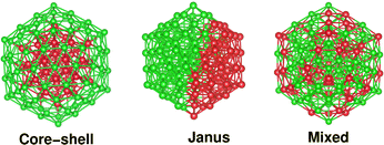
To prepare the three structural configurations containing a fixed number of total atoms and the same composition, we started from a large 147-atom sized icosahedral structure of a pristine Pd147 cluster and constructed the three initial structural patterns considering two compositions – Pd55X92 (i.e. Pd-poor) and Pd92X55 (i.e. Pd-rich) for each bimetallic Pd–X nano-alloy, where “X” indicates each of the remaining eight elements. Though the physical properties of a nano-system are size and shape dependent,20 our choice of an atomic shell structured icosahedron as the overall host structure is motivated by its high stability for the noble metal elemental nano-particles.21 Moreover, it is rather easy to construct the three structural patterns with the same composition, out of an icosahedron. Then, we optimized the three structures for each bimetallic nano-alloy. Considering the optimized structures, we have studied the relative stability among the three structural patterns for each bimetallic nano-alloy of either composition. Subsequently, we have analyzed the structural and electronic properties of the three patterns using first principles density functional theory (DFT) calculations and their variations along the bimetallic Pd–X nano-alloy series. Our analysis of Crystal Orbital Hamiltonian Populations22 indicates that the relative stability is mainly governed by the change in atom–atom covalency from one structural pattern to another for each bimetallic Pd–X nano-alloy of fixed composition. We note that the three patterns are also distinctly identified in terms of an orbital hybridization index. Finally, we have analyzed the trend in catalytic activity using the d-band model23 for the three structures of each bimetallic nano-alloy. Our analysis of the occupied d-band center's position indicates that the catalytic activity for most of the studied bimetallic Pd–X nano-alloys would lie in-between that of a pristine Pt147 and Pd147 cluster in either composition limit, except for the Pd-poor Pd–Ag nano-alloy. The overall analysis of both the relative stability and catalytic properties implies that the bimetallic Pd–Ni nano-alloy would be the most suitable candidate to design a non-Pt catalyst – particularly its Janus and mixed structures for the Pd-poor composition and the core–shell structure for the Pd-rich composition (with the Pd atoms at the surface). To cross-check the size effects within the motif of an atomic shell structured icosahedron, we have carried out additional calculations for a 55 atom sized bimetallic PdNi nano-alloy considering its two compositions, i.e. Pd13Ni42 (Pd-poor) and Pd42Ni13 (Pd-rich) nano-alloys, which confirm the trend observed for the 147 atom-sized binary Pd–X nano-alloys. Finally, we have confirmed the predicted trend of catalytic activity for the three structures of the bimetallic Pd–Ni nano-alloy relative to that of the pristine Pd147 cluster, by rigorous analysis of the absorption reaction with a CO molecule on their surface.
2 Construction of three structural patterns and computational details
It should be noted that the icosahedron-like concentric cell structure has been predicted previously as the ground state geometry for larger sized pristine Pd nano-clusters.24 An icosahedron of 147 atoms forms a third closed shell icosahedron with 55-atoms in the core and 92-atoms at the outer shell. Therefore, an initial core–shell structural pattern for a bimetallic X55Pd92 nano-alloy can be easily constructed from the pristine Pd147 cluster by replacing its 55 core atoms with the X elemental atoms. Likewise, an initial structure of Janus pattern for a bimetallic X55Pd92 nano-alloy is prepared by replacing a hemispherical fraction of Pd55 from one side, by 55 atoms of the X element, so that the X55 and Pd92 fractions are sandwiched side-by-side. Finally, the initial structure of a mixed pattern for a bimetallic X55Pd92 nano-alloy is formed by random mixing of the 55 X atoms with 92 atoms of Pd throughout the whole structure. Fig. 1 shows the initial structural pattern for a core–shell, Janus and mixed bimetallic nano-alloy with X55Pd92 composition. On the other hand, the initial structural patterns for the core–shell, Janus and mixed structures of a bimetallic Pd55X92 nano-alloy are obtained from those of the X55Pd92 nano-alloy by interchanging between the X atoms and Pd atoms. We have additionally considered 55 atom-sized bimetallic Ni–Pd clusters to cross-check the cluster-size effect.The calculations reported in this study were based on DFT within the framework of the pseudo-potential plane wave method, as implemented in the Vienna ab initio Simulation Package (VASP).25 We used the Projected Augmented Wave (PAW) pseudo-potential26,27 coupled with the generalized gradient approximation (GGA) to the exchange correlation energy functional as formulated by Perdew, Burke and Ernzerhof (PBE).28 The 3d as well as 4s electrons for atoms of Co, Ni and Cu; 5s as well as 4d electrons for atoms of Rh, Pd and Ag; and the 6s and 5d electrons for the atoms of Ir, Pt and Au were treated as the valence electrons. The wave functions were expanded in the plane wave basis set with the kinetic energy cut-off of 300 eV. For the cluster calculations, a simple cubic super-cell with each side of 28 Å was used with the periodic boundary conditions, where two neighboring clusters were kept separated by around 12 Å vacuum space. The large cell-size essentially makes the interaction between cluster images negligible. Reciprocal space integrations were carried out at the Γ point. All structures were optimized using the conjugate gradient and the quasi-Newtonian methods until all the force components were less than a threshold value of 0.001 eV Å−1. The convergence of the energies with respect to the cut-off as well as the k-mesh values were checked. Due to the presence of heavy 4d and 5d atoms, non-collinear DFT calculations including spin–orbit interactions were performed for all calculations.
3 Results and discussion
The major relevant properties of the constituting elements, which influence the formation of binary nano-alloys, are atomic radius, bulk cohesive energy and surface energy, and electro-negativity. Table 1 contains the values of these quantities for the constituent species. It is seen from Table 1 that the cohesive energy and surface energy of Cu, Ag and Au are lower with respect to the corresponding values of Pd, while the other elements have higher cohesive energy and surface energy. Furthermore, Ir (Cu) possesses the biggest (smallest) atomic radius and Au (Co) is associated with the most (least) electro-negativity. Ir (Ag) also possesses the highest (smallest) cohesive energy and surface energy. In the following, we have analyzed the optimized structures and the trend in relative stability, electronic and catalytic properties among the three structural patterns for each bimetallic nano-alloy.| Element | r (Å) | E c (eV per atom) | S (J m−2) | χ (Pauli scale) |
|---|---|---|---|---|
| a CRC Handbook of Chemistry and Physics, ed. D. R. Lide, CRC Press, Boca Raton, Florida, 84th edn, 2003. | ||||
| Co | 1.52 | 4.39 | 2.55 | 1.88 |
| Ni | 1.49 | 4.44 | 2.38 | 1.91 |
| Cu | 1.45 | 3.49 | 1.79 | 1.9 |
| Rh | 1.73 | 5.75 | 2.70 | 2.28 |
| Pd | 1.69 | 3.89 | 2.05 | 2.20 |
| Ag | 1.65 | 2.95 | 1.25 | 1.93 |
| Ir | 1.80 | 6.94 | 3.00 | 2.20 |
| Pt | 1.77 | 5.84 | 2.475 | 2.28 |
| Au | 1.74 | 3.81 | 1.50 | 2.54 |
3.1 Optimized structures
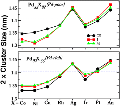
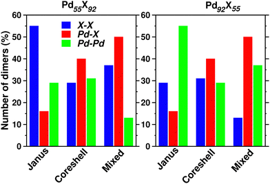
Upon structural optimization for the three structures of every bimetallic Pd–X nano-alloy, the overall icosahedral structural pattern remains intact for each structural pattern. However, the effective cluster sizes exhibit some variation along the Pd–X series. We define cluster size as the average distance between the cluster center and the outermost surface atoms. Details of our estimated cluster size for the Pd–X clusters with their respective optimized structure are given in the ESI.‡Fig. 2 shows the plot of our estimated cluster size of the three morphologies for each binary nano-cluster in both the composition limits. First, starting from an unoptimized cluster size of 0.703 nm (the same as the cluster size for the optimized pristine Pd147 cluster), it is seen that the optimized cluster sizes for the binary Pd–X clusters vary within a range of 0.66–0.73 nm. The overall trend of variation remains almost similar for both the compositions. As expected, the size for the Pd–Ni or Pd–Co cluster with their Pd-poor composition remains smaller due to their smaller atomic size. Then, the cluster size shows an increasing trend with the increasing atomic number of the X element. It is to be noted that the cluster size peaks for the binary Pd–Ag clusters. This could result from the smaller atom–atom interaction due to the presence of a filled 4d valence orbital of the Ag atom. Interestingly, we note that the variation of cluster size is qualitatively understandable from the variation of orbital hybridization as discussed in Section 3.3.In a bimetallic Pd–X nano-alloy, there are three types of nearest neighbor (NN) bonds-Pd–Pd, Pd–X and X–X. The number of a similar type of NN bonds for each structural pattern along the Pd–X nanoalloys within a fixed composition also remains approximately the same with varying X element. The plot of the overall percentage for the total number of X–X, Pd–X and Pd–Pd NN bonds with respect to the overall total NN bonds associated with each of the three structures constructed out of a 147 atom icosahedron is shown in Fig. 3 for either composition. Interestingly, we note that the three structural patterns are characterized by the dominance or deficiency of a specific type of NN bond. For the Pd55X92, i.e. Pd-poor nano-alloys, it is seen that:
• the optimized core–shell structure involves the most number of Pd–X NN bonds and the least number of X–X NN bonds,
• the optimized Janus structure involves the most number of X–X NN bonds and the least number of Pd–X NN bonds,
• the optimized mixed structure involves the most number of Pd–X NN bonds and the least number of Pd–Pd NN bonds
On the other hand, the sequence of NN bond types for the Pd92X55, i.e. Pd-rich nano-alloys, is
• the optimized core–shell structure involves the most number of Pd–X NN bonds and the least number of Pd–Pd NN bonds,
• the optimized Janus structure involves the most number of Pd–Pd NN bonds and the least number of Pd–X NN bonds,
• the optimized mixed structure involves the most number of Pd–X NN bonds and the least number of X–X NN bonds
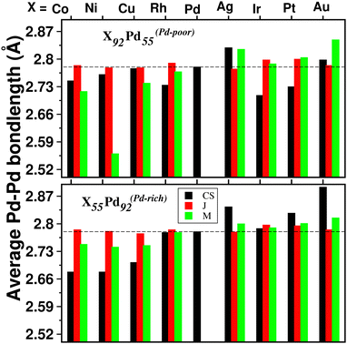
For a bimetallic Pd55X92 or Pd92X55 nano-alloy, the NN bond-length for each of the three types of NN bonds is also different in the optimized structures of the three patterns. Fig. 4 shows the variation of only 〈Pd−Pd〉 NN bond-length (“〈–〉” indicates averaged value) for the three optimized structures of each Pd–X nano-alloy to compare it with that of the pristine Pd147 nano-cluster. It is seen that the 〈Pd−Pd〉 NN bond-length for the Janus structures, especially for the Pd-rich composition, is less affected with respect to the 〈Pd−Pd〉 NN bond-length of the pristine Pd147 nano-cluster. For the other two structural patterns, it shows considerable variation for each Pd–X alloy in either composition. For example, in the case of alloying of Pd with the 3d element, for the Pd-poor composition, the 〈Pd−Pd〉 NN bond-length is reduced (compared to that of the pristine Pd147 nano-cluster) for the optimized mixed structure and the reduction is the most for the optimized mixed structure of the Pd55Ni92 nano-alloy. In the case of the Pd-rich composition of the Pd-3d nano-alloys, both the optimized core–shell and mixed structures have lower 〈Pd−Pd〉 NN bond-length and the reduction is comparatively more for the core–shell structure. In the case of alloying of Pd with the plasmonic elements like Ag and Au, it is seen that the 〈Pd−Pd〉 NN bond-length for both compositions has increased for the optimized core–shell and mixed structures and the enhancement is the most for the core–shell structure of the Au55Pd92 nano-alloy. However, the core–shell structure for the bimetallic Au55Pd92 nano-alloy with the Au-atoms at the core is not a stable structure as will be seen in the subsequent section.
3.2 Trend in relative stability
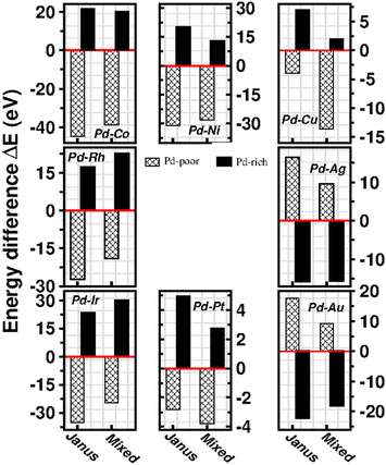
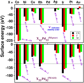
To analyze the relative stability among the three structures of a binary Pd–X nano-alloy with a fixed composition, we have calculated the total energy difference (ΔE) for the optimized Janus/mixed structure with respect to the optimized core–shell structure, i.e. ΔE = Ejanus/mixed − Ecore−shell; E being the DFT calculated total energy for the optimized geometry. A +ve ΔE means that the optimized core–shell structure with that chosen ordering for the two species of atoms is more stable, and −ve ΔE means that the optimized core–shell structure with such ordering, has lower stability than that of the optimized Janus/mixed structure. Therefore, if ΔE is +ve for both the optimized Janus and mixed structures, then the core–shell structure of that composition with that chosen ordering of the two atomic species, is the most stable structure for that binary nano-alloy. On the other hand, if ΔE is −ve for both the optimized Janus and mixed structures, then the core–shell structure of that composition and ordering, will be the least stable. Fig. 5 shows the plot of our calculated ΔE for both the compositions of each bimetallic Pd–X nano-alloy. It is seen that Pd-rich binary Pd–Co, Pd–Ni, Pd–Cu and Pd–Pt nano-alloys have a similar trend in the relative stability with respect to the order of preference among the three structural patterns, which is core–shell (Pd–shell) > mixed > Janus. Likewise, the order of the relative stability among the three structural patterns in case of the Pd-rich Pd–Rh and Pd–Ir nano-alloys is core–shell (Pd–shell) > Janus > mixed and that for the Pd-rich binary Pd–Ag and Pd–Au nano-alloys is Janus > mixed > core–shell (Pd–shell). Inversion of the composition affects the order of the relative stability among the three optimized structural patterns as seen for most of the Pd-poor binary nano-alloys. It is seen from Fig. 5 that the order of the relative stability for the Pd-poor bimetallic Pd–Co, Pd–Ni, Pd–Rh and Pd–Ir nanoalloys is similar to Janus > mixed > core–shell (Pd–core); for the Pd-poor bimetallic Pd–Cu and Pd–Pt nano-alloys, it is similar to mixed > Janus > core–shell (Pd–core); for the Pd-poor Pd–Ag and Pd–Au nano-alloys, the order of relative stability is core–shell (Pd–core) > mixed > Janus. For further analysis of the relative stability among the three structural patterns for each binary Pd–X nano-cluster of fixed composition, we have also calculated their formation energies,29,30 as given in Section S2 of the ESI.‡ According to our formulation, a negative formation energy implies a mixing trend between the two species of constituting atoms, while its positive value implies a segregated trend. This analysis shows that the formation energy for each bimetallic Pd–X cluster is most negative for the most stable of the three structures. Our next analysis aims to understand this observed trend in the relative stability in terms of elemental, atomic and electronic properties of the binary nano-alloys. , where E(AmBn) is the total energy of the binary AmBn nano-alloy and εA and εB are the bulk cohesive energies per atom of the A and B elements, respectively; Ns is the total number of surface atoms in the optimized structure. As we are dealing with icosahedral symmetry-based structures containing an equal number of surface atoms for each of the three structures in every binary nano-cluster studied in this work, the division by Ns is, therefore, immaterial in the present work. Regarding the effects of surface energy contribution on the relative stability, a higher surface energy usually corresponds to a lower stability and vice versa. Our calculated surface energy for the three structures of each bimetallic Pd–X nano-alloy is shown in Fig. 6. The order of energetic stability among the three structures is also mentioned in Fig. 6 for each binary Pd–X nano-alloy for comparison purposes. It is seen that the structure of the highest stability is associated with the least surface energy for most of the bimetallic nano-alloys in either composition. It should also be noted from Fig. 6 that the magnitude of the surface energy for the bimetallic Pd–Ag and Pd–Au nano-alloys is much smaller, especially for their Pd-poor composition, compared to that of the other bimetallic nano-alloys. This is in accordance with a known fact that Ag and Au atoms tend to segregate mostly at the surface in the case of the Ag or Au-related bimetallic nano-alloys.32
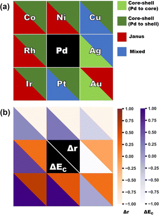
In order to clarify the importance of two factors for a bimetallic Pd–X nanoalloy, namely the difference between the two constituting elemental species of their atomic radii (i.e. Δr = r(X) − r(Pd)) and bulk cohesive energies (i.e. ΔEc = Ec(X) − Ec(Pd)), Fig. 7(a) displays the color-coded plot of the most stable structure for each bimetallic nano-alloy of either composition and Fig. 7(b) represents the color-coded plot of the values for the Δr and ΔEc of the corresponding (X,Pd) pair. In the case of either plot, each box except for the central box represents a binary Pd–X nano-alloy. Furthermore, each box is divided into two triangular parts which represent two different entities. In the case of Fig. 7(a), the lower-left triangle and the upper right-triangle of each box represent the stable structure for the Pd-poor and Pd-rich compositions, respectively, of a bimetallic Pd–X nano-alloy. In the case of Fig. 7(b), each box represents the same Pd–X pair as that of Fig. 7(a). However, it is important to note that the lower-left triangle and upper right triangle now represent the values of ΔEc and Δr, respectively, for the corresponding pair. It is seen from Fig. 7(b) that the binary 3d-Pd pairs have large −ve Δr and this is the main driving factor to decide the stable structure – in the Pd-rich composition, the core–shell structure with larger sized Pd-atoms in the shell acquired the most stability, while in the Pd-poor composition, a core–shell structure with the Pd-atoms in the shell is not allowed to form with our chosen composition in the icosahedral structure. Rather, the relative stability is mostly decided by ΔEc for the Pd-poor composition. Large ΔEc favors the Janus structure for the Pd-poor Pd–Co and Pd–Ni nano-alloys, while small ΔEc favors a mixed structure for the Pd-poor Pd–Cu nano-alloy. For the Rh–Pd, Ir–Pd and Pt–Pd pairs, there is competition between ΔEc and Δr as both are +ve. For Pd–Ir and Pd–Rh pairs, ΔEc dominates, which favors the core–shell structure with Pd-atoms at the surface for the Pd-rich composition and favors the Janus structure for the Pd-poor composition. For the Pd-rich Pd–Pt nano-alloy, ΔEc wins and stabilizes the core–shell structure with Pd-atoms at the surface. For the Pd-poor Pd–Pt combination, the situation becomes frustrated and the mixed structure gets stabilized. On the other hand, in the case of the Pd-poor Pd–Ag, Pd–Au nano-alloys, the relative stability is dominated by surface segregation of Ag/Au due to their lower surface energy as seen above. Here, the term “surface segregation” implies that the element between the two constituting species, possessing lower surface energy, tends to segregate at the surface of the nano-alloy.
For the bimetallic Pd55X92 (i.e. Pd-poor) nano-alloys, it is seen that:
• NJX−X > NMX−X > NC−SX−X
• NMX−Pd > NC−SPd−X > NJPd−X
• NC−SPd−Pd > NJPd−Pd > NMPd−Pd
For the bimetallic Pd92X55 (i.e. Pd-rich) nano-alloys, it is seen that:
• NC−SX−X > NJX−X > NMX−X
• NMX−Pd > NC−SPd−X > NJPd−X
• NJPd−Pd > NMPd−Pd > NC−SPd−Pd
We note that the relative bond strength and the relative number of various types of dimers in a binary nano-alloy can give a qualitative understanding about the trend in the calculated relative stability among the three structural patterns for that nano-alloy system. For example, consider the case of the bimetallic Pd–Co nano-alloy for which the order of bond strength for the three types of NN dimers is Co–Co > Pd–Co > Pd–Pd. In the case of the Pd-poor bimetallic Pd–Co nano-alloy, the order of dominance for the number of strongest Co–Co NN bonds in the three structures is NJCo−Co > NMCo−Co > NCSCo−Co. Interestingly, the order of relative stability follows the same trend, i.e. J > M > C–S for the Pd-poor Pd–Co nano-alloy. On the other hand, for the Pd-rich binary Pd–Co nano-alloy, we find that the total number of Pd–Co and Co–Co NN bonds in the three structures varies as NC−S(Co−Co)+(Pd−Co) > NM(Co−Co)+(Pd−Co) > NJ(Co−Co)+(Pd−Co). Again, the trend in the relative stability for the Pd-rich Pd–Co nano-alloy is C–S > M > J. We figure out such similarity for all the bimetallic nano-alloys of either composition, in the trend of variation between the order of relative stability and the order of dominance for a combination of some specific types of NN dimers. Does this similarity in the variation of the two quantities among the three structural patterns indicate some sort of relation between the relative stability and NN bond strength?
In order to investigate the change of atom–atom co-valency among the three structural patterns upon alloying of Pd nano-cluster with the atoms of different elements, we have analyzed the Integrated Crystal Orbital Hamiltonian Population (ICOHP)22 for the three structures of each bimetallic nano-alloy. COHP is the hopping-weighted density of states between two adjacent atoms and its negative value indicates bonding interactions. ICOHP is the energy integration of all COHP up to the energy of the highest occupied molecular orbital (HOMO) and it measures the strength of covalency for the bonds. We have calculated ICOHP averaging over all the NN interactions for each bimetallic Pd–X nano-alloy including the pristine Pd147 cluster. Our calculated ICOHP for the optimized structure of three patterns is shown in Fig. 8 as a function of electron energy for every bimetallic nano-alloy of both compositions. The plots are obtained by averaging the ICOHP values over both the spin channels for every nano-alloy. It is seen from the plot of ICOHP that the structure corresponding to the highest stability is mostly associated with the enhanced covalency (i.e. more −ve ICOHP) throughout the bonding region. To compare the values of ICOHP at the Fermi energy among the three structures for every bimetallic nano-alloy, we have calculated the difference of ICOHP for the optimized Janus/mixed structure with respect to the ICOHP for the optimized core–shell structure of the same system, i.e. ΔICOHP = ICOHP(Janus/mixed) − ICOHP(core−shell). A +ve ΔICOHP means that the optimized core–shell structure with our chosen ordering for the two species of atoms possesses enhanced covalency, and −ve ΔICOHP means that the optimized core–shell structure with such ordering, has lower covalency than that of the optimized Janus/mixed structure. It is to be noted that the formulation of ΔICOHP and the interpretation of its sign have similarities with those of ΔE as defined in Section 3.2. Fig. 8 also shows the plot of our calculated ΔICOHP for all the Pd-poor (patterned bars) and Pd-rich (filled bars) nano-alloys. From the plot of ΔICOHP, it is interesting to note that the ΔICOHP for each bimetallic nano-alloyed cluster exhibits a similar trend of variation as seen in the variation of ΔE in Fig. 5. It, therefore, clearly indicates a one-to-one correspondence between the relative stability and a change of atom–atom covalency among the three structures. That is, a change in the relative stability among the three structures is intrinsically driven by the change of the atom–atom covalency. The more stable structure is associated with a higher atom–atom covalency and it is the smallest for the least stable structure.
3.3 Microscopic characterization of the three morphologies
To characterize the three structural patterns for a bimetallic nano-alloy, one well-known quantity is the radial distribution function (RDF). The RDF for a bimetallic nano-structure is defined as the number of atoms NA,B(r) of species A or B in a shell at a distance between r and r + Δr from the center of the cluster42i.e. . In the case of core–shell/Janus binary A–B nano-structures, the first peaks in the plots of ρA and ρB are well separated by a radial distance. In other words, the probability distribution for bimetallic core–shell/Janus nanoparticles exhibits bimodal distributions, while bimetallic alloyed nano-particles display narrow size distributions in the plot of RDF.43 Furthermore, the ordering of the two elemental species in the core–shell structure could be perceived by analyzing the segregation energy.44 Likewise, a mixed structure is usually characterized by enhanced mixing energy and hetero-atomic bonds.6,45 It is, therefore, seen that the core–shell and Janus structural patterns of a bimetallic nano-alloy are not distinctly identified in terms of RDF or mixing energy. In this context, we find that the “Orbital Hybridization Index” could be a useful microscopic quantity that captures a clear distinction among the three structural patterns. As the constituting atomic species have nearly filled valence orbitals, then it is expected that the systems are associated with a large orbital hybridization. To quantify the total orbital hybridization, we have calculated the orbital hybridization index,45–47 defined as
  where k and l correspond to the orbital indices – s, p and d, and wIi,k (wIi,l) is the projection of i-th Kohn–Sham orbital onto the k (l) spherical harmonic centered at atom I, integrated over a sphere of specified radius. The spin index is implicit in the summation.
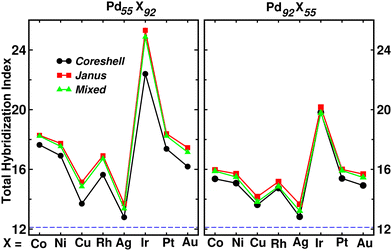
Fig. 9 shows the plot of total hybridization index (hsd + hpd + hsp) for each of the Pd55X92 (left) and Pd92X55 (right) clusters. The value of the total orbital hybridization index for the pristine Pd147 cluster is also marked with the dashed line for comparison with those of the bimetallic nano-alloys. It is seen that the total hybridization for each of the three structures for every bimetallic nano-alloy has enhanced in either composition compared to that of the pristine Pd147 cluster, due to the increase of itinerant electrons in the bimetallic nano-alloys. The enhancement of the total hybridization is the most for the bimetallic Pd–Ir nano-alloy due to the presence of more itinerant valence d-electrons of Ir, which results in more p–d and s–d hybridizations, and thereby the total hybridization. On the other hand, the enhancement of orbital hybridization for the Pd–Ag nano-alloy is the least due to reduced itinerancy of the valence d-electrons of Ag. It is seen that the variation of total hybridization index in Fig. 9 is well correlated with the variation of cluster size in Fig. 2 in the sense that a lower hybridization results a higher cluster size and vice versa. The interesting point to note from the plot of the total hybridization index within a fixed composition is that the optimized Janus structure for most of the studied bimetallic nano-alloys possesses relatively higher value compared to that of the optimized core–shell and mixed structures for the respective system. In addition, the optimized core–shell structure has the least total orbital hybridization index, while the optimized mixed structure has intermediate total orbital hybridization for each bimetallic cluster. The three structural patterns for a bimetallic nano-alloy, therefore, possess a clear trend in the variation of total orbital hybridization index – most for Janus, intermediate for mixed and least for core–shell patterns.
3.4 Trend in catalytic properties
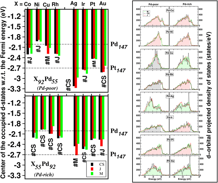
The catalytic activity of the catalysts for a given reaction relies on the activation barrier of the rate-determining step or absorption ability of an intermediate included in the rate-determining step.48,49 For a catalytic process over a transition metal, the adsorption energies of different molecules scale with each other as do the transition state energies and reaction energies.50–54 This underlying concept is the basis of the d-band model. Instead of determining the energy of the intermediates and transition states for each catalyst, the celebrated d-band center model proposed by Hammer and Norskov23 gives a straight forward way to relate the rate of catalytic activity to the absorption energy and thereby the electronic structure of the transition metal catalyst's surface. Therefore, the position of the d-band center with respect to the Fermi energy is regarded as a first order descriptor of the propensity of a transition metal catalyst to bind to absorbates. According to this model, the trend in binding of the absorbate on the surface of the catalyst is an effective indicator about the rate of the catalytic activity for the catalytic surface. For an efficient catalytic process, this bond-strength of the absorbate with the catalytic surface will not be too strong or too weak. This is due to the fact that if this bonding is very strong, then the barrier height for the desorption process, i.e. the removal of the absorbate from the catalytic surface after the reaction is very high. Likewise, if the bonding is very weak, then the barrier height for the absorption process is very high which limits the overall reaction kinetics too. In fact, this is readily understandable as the plot of the catalyst's activity against the binding of the absorbate results mostly in a so-called Volcano curve for efficient catalytic reactions.55 It should be mentioned that the Volcano plot gives an effective measure for catalytic activity, which has been extensively used for various heterogeneous catalytic reactions.56 The d-band center model is a more fundamental approach to predict catalytic activity as it correlates the absorbate–surface bond strength, i.e. the macroscopic catalytic performance, with the microscopic electronic structure of the surface atoms for the transition metal catalysts. According to this model, an up-shifting of the occupied d-band center towards the Fermi energy corresponds to a stronger absorption strength and vice versa. For our binary nano-alloys, we have calculated the position of the occupied d-band center as where ρ = d-density of states, E = the d-level energy and ρdE = the number of d-states in the energy interval E and E + dE. Our calculated position for the occupied d-band center of the three structures for each bimetallic nano-alloy, with respect to the respective EHOMO (fixed at zero), is plotted in Fig. 10. It should be noted here that the calculated d-band center position is averaged over both the spin channels. The corresponding values for the pristine Pd147 and Pt147 clusters are indicated with horizontal dashed lines to compare them with the d-center positions of the studied bimetallic nano-alloys. For further clarification, the d-orbital projected density of states (d-PDOS) for the three structures of each bimetallic nano-alloy is also shown in the right panel of Fig. 10 and the occupied d-states for the structure having the maximum up-shifting of the occupied d-states is marked with the shaded region.
From our plot of the occupied d-center position in Fig. 10, it is seen that the positions of the occupied d-band center for either composition of the bimetallic Pd–Ni nano-alloys, i.e. Pd55Ni92 and Pd92Ni55 nano-clusters, have up-shifted for each structure with respect to that of the pristine Pd147 cluster. This implies that the bimetallic Pd–Ni nano-alloy will have stronger interaction with the absorbate. Similar up-shifting is also found for the mixed structure of the Pd-rich bimetallic Pd–Cu nano-alloy, i.e. for the Pd92Cu55 cluster. For the rest of the studied bimetallic nano-alloys, the occupied d-band center positions fall in-between those of the pristine Pd147 and Pt147 clusters. Consequently, their catalytic activity is also expected to be intermediate of those of the pristine Pt147 and Pd147 clusters. Furthermore, it is clearly seen from Fig. 10 that the difference in the positions of the occupied d-band center among the three structures is very small for the bimetallic Pd–Ni and Pd–Pt nano-alloys in either composition limits. Therefore, it indicates that the catalytic activity for these systems is not affected much with the change of their structural patterns. In reality, the catalytic activity, however, depends mostly on the availability of the catalytically active sites on the surface. With respect to the importance of the structural pattern on the catalytic performance, our analysis of d-band center position suggests that:
II. the Janus structure will have strong absorbate–cluster interaction in the cases of the bimetallic Pd–Co, Pd–Ni and Pd–Pt nanoalloys,
III. the mixed structure in the cases of the bimetallic Pd–Ag, Pd–Au nanoalloys.
Considering the structure which has the most up-shifting of the occupied d-band center position, among the Pd-poor nano-alloys, i.e. the X92Pd55 nanoalloys, the predicted up-shifting order would be X = Ni(J) > Cu(C–S) > Co(J) > Rh(C–S) > Pt(J) > Au(M) > Ir(C–S) > Ag(M). Here “C–S” stands for core–shell structure, “J” for Janus structure and “M” for Mixed structure.
II. the mixed structure in the cases of the bimetallic Pd–Cu, Pd–Ag and Pd–Au nanoalloys.
Considering the structure which has the most up-shifting of the occupied d-band center position among the Pd-rich nano-alloys, i.e. the X55Pd92 nanoalloys, the predicted up-shifting order would be X = Cu(M) > Ni(J) > Co(J) > Rh(J) > Pt(J) > Au(M) > Ag(M) > Ir(J).
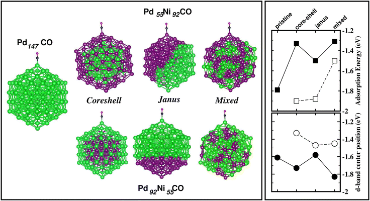
The energetically most stable structure for each bimetallic nano-alloy of either composition is also mentioned in Fig. 10 with the # symbol. In most of the cases, the catalytically active structure does not correspond to the energetically most stable structure. This is in accordance with the fact that a non-equilibrium system is prone to enhanced catalytic activity.57 Moreover, it is seen that the Janus structure appears more frequently as the catalytically most active structure, which may result from the presence of a large strained interface between two species of atoms in the Janus structure.58 According to our analysis of the occupied d-band center position, the bimetallic Pd–Ni nano-alloy has the most up-shifting of the occupied d-center towards its Fermi level for both compositions. For direct comparison of the trend towards catalytic activity relative to that of the pristine Pd147 cluster, we performed rigorous analysis of the absorption of a CO molecule on each structure of the bimetallic Pd–Ni nano-alloy of either composition. To simplify our analysis, we consider absorption of a carbon-monoxide molecule at the atop position on a least coordinated vertex site: on a surface Pd-site in the case of the pristine Pd147 cluster and the three structures of Pd-rich bimetallic Pd–Ni cluster, i.e. Pd92Ni55 cluster. In the case of the three structures of Pd55Ni92 cluster, we consider absorption on a surface Ni-site at the vertex position. The optimized CO-absorbed structures are shown in Fig. 11. It should be noted here that previous works also found that absorption of a CO molecule at the atop position on a Pd–surface, is energetically more favorable.59
Then, we calculated the absorption energy for the CO-absorbed systems using the formulation Eabs = E(NimPdnCO) − E(NimPdn) − E(CO). To understand the trend in the calculated absorption energy, we have also analyzed the occupied d-band center position for the absorption site. Our calculated absorption energy and the position of the occupied d-band center for the absorption site, are also shown in Fig. 11. First, it should be mentioned that our calculated absorption energy for the pristine Pd147 cluster [Eabs(Pd147) = 1.79 eV] is comparable with the previously calculated absorption energy of a CO molecule on a Pt(111) surface [Eabs(Pt(111)/CO) = 1.64 eV]60 or Pt55 nano-cluster [Eabs(Pt55CO) = 2.04–2.37 eV] by DFT-PBE calculations.59 From our plot of the calculated absorption energy in Fig. 11, it is seen that the overall magnitude of the absorption energy for the Pd-poor Pd–Ni nano-alloy is more than that of the Pd-rich Pd–Ni nano-alloy. This is due to the fact that the bond-strength of the CO molecule with a surface Ni atom is more than that with a surface Pd atom. The right panel of Fig. 11 also shows the position of the occupied d-band center relative to the Fermi energy for the atom at the absorption site. Interestingly, the occupied d-band center is up-shifted more for each structure of Pd-poor bimetallic Pd–Ni nano-alloy compared to that of the Pd-rich Pd–Ni nano-alloy, which is consistent with the enhanced absorption trend for the Pd-poor bimetallic Pd–Ni nano-alloy.
3.5 Exploring size effects
So far, the calculated results as discussed above are based on the cluster size of 147 atoms. In order to explore the possible cluster size effects on the studied properties, we have repeated the analysis of the relative stability in terms of energy difference, formation energy and surface energy; the trends in the orbital hybridization and catalytic activity considering a 55-atom sized icosahedral geometry only for the bimetallic Pd–Ni nano-alloy. It should be mentioned here that a 55-atom sized icosahedron is the second closed-shell structure containing 13 atoms inside and 42 atoms on the outermost surface. Therefore, we focus on the three structural patterns for two compositions – Pd13Ni42 (Pd-poor) and Pd42Ni13 (Pd-rich) nano-alloys. The calculated results are plotted in Fig. 12. It is seen that the predicted order of relative stability from the analysis of ΔE and formation energy, is J > M > CS for the Pd13Ni42 cluster and CS > M > J for the Pd42Ni13 nano-cluster. In addition, the observed trend in the relative stability is in accordance with the variation of their surface energy. Furthermore, the variation of orbital hybridization among the three structures of the 55-atom sized binary Pd–Ni nano-cluster also indicates the most total hybridization for the Janus structure and least for the core–shell structure. Moreover, the position of the occupied d-center with respect to the Fermi level indicates the same trend of catalytic activity among the three structures of the 55-atom PdNi nano-alloy as seen for the 147-atom binary PdNi cluster with either composition limit. Therefore, this analysis indicates that the cluster size has no significant effect on the overall trend of variation for the studied properties among the three structural patterns for the binary Pd–X nano-alloys.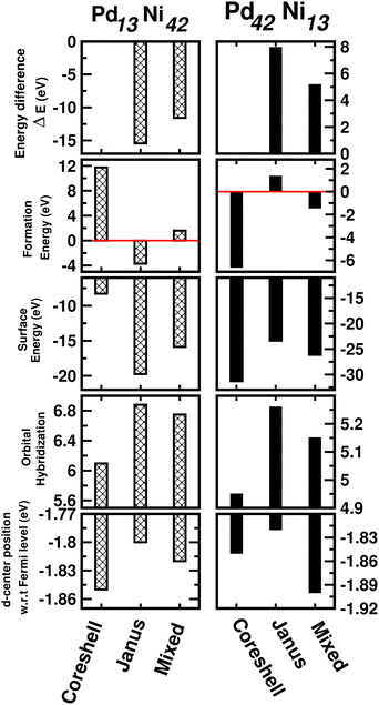 | ||
| Fig. 12 Plot of total energy difference as defined in Section 3.2, formation energy as defined in the ESI,‡ surface energy as defined in Section 3.2.1, orbital hybridization as defined in Section 3.3 and position of the d-band center as defined in Section 3.4 for the optimized core–shell, Janus and Mixed structures of the 55-atom sized bimetallic Pd–Ni cluster in both compositions, i.e. Pd13Ni42 (left panel) and Pd42Ni13 clusters (right panel). | ||
4 Summary and conclusions
Using DFT calculations, we have analyzed the relative structural stability, electronic and catalytic properties among the core–shell, Janus and mixed structural patterns for eight bimetallic Pd–X nano-alloys (X = Co, Ni, Cu, Rh, Ag, Ir, Pt, and Au) considering two compositions – a Pd-poor and a Pd-rich compositions. It is seen that the relative stability depends on the composition and the type of “X” element. The driving factors to determine the relative stability are found to be: the atomic-radius difference of the two constituting elemental species in the cases of Pd-3d pairs; competition of the differences in their atomic radii and also in their bulk cohesive energies for the bimetallic Pd–Rh, Pd–Ir and Pd–Pt pairs; and difference of surface energies in the case of Pd–Ag and Pd–Au pairs. Our analysis of Integrated Crystal Orbital Hamiltonian Population indicates that the relative structural stability among the three patterns is intrinsically governed by the change of atom–atom covalency – a more stable structure is associated with higher atom–atom covalency and it is smaller for the least stable structure. Furthermore, the three structures of each bimetallic Pd–X nano-alloy can be distinctly identified in terms of an orbital hybridization index – our analysis of total orbital hybridization index, shows that the Janus, mixed and core–shell structures are associated with the highest, intermediate and least total orbital hybridization, respectively. The trend in the catalytic activity for the bimetallic Pd–X nano-alloys is predicted by analyzing the shifting of the occupied d-band center position. We find that most of the Pd–X nano-alloys are expected to have catalytic activity in-between those of pristine Pt and Pd clusters of the same size. Among the three structures, the catalytically most active structure for the Pd–X nano-alloys is mostly different from the energetically most stable structure. The bimetallic Pd–Ni nano-alloy exhibits the most up-shifting of the occupied d-band center position, thereby implying stronger interaction with an absorbate molecule. Our analysis of absorption reaction for a CO molecule on a Pd–Ni cluster exhibits a similar trend of variation for the absorption energy as predicted from the analysis of the occupied d-band center shifting. To verify the cluster size effect on the studied properties, we have further repeated our analysis for two compositions of a 55-atom sized binary Pd–Ni cluster. Our study in the present work indicates that the bimetallic Pd–Ni nano-alloys are expected to be the best combination to develop stable and catalytically active non-Pt nano-alloys.Conflicts of interest
There are no conflicts to declare.Acknowledgements
T. S.-D. and S. D. acknowledge funding from J. C. Bose National Fellowship (JCB/2020/000004). AG acknowledges a DST-INSPIRE Fellowship for funding.References
- M. B. Gawande, A. Goswami, T. Asefa, H. Guo, A. V. Biradar, D.-L. Peng, R. Zboril and R. S. Varma, Chem. Soc. Rev., 2015, 44, 7540–7590 RSC.
- J. Lim, B. G. Jeong, M. Park, J. K. Kim, J. M. Pietryga, Y.-S. Park, V. I. Klimov, C. Lee, D. C. Lee and W. K. Bae, Adv. Mater., 2014, 26, 8034–8040 CrossRef CAS PubMed.
- J. Rick, M.-C. Tsai and B. J. Hwang, Nanomaterials, 2015, 6, 5, DOI:10.3390/nano6010005.
- K. McNamara, S. A. M. Tofail, N. D. Thorat, J. Bauer and J. J. E. Mulvihill, In Biomedical Applications of Nanoalloys. Nanoalloys: From Fundamentals to Emergent Applications, 2nd edn, ed. F. Calvo, Elsevier, 2020, pp. 381–432 Search PubMed.
- S. T. Selvan, P. K. Patra, C. Y. Ang and J. Y. Ying, Angew. Chem., Int. Ed., 2007, 46, 2448–2452 CrossRef CAS PubMed; S. Duan and R. Wang, Prog. Nat. Sci.: Mater. Int., 2013, 23(2), 113–126 CrossRef.
- R. Ferrando, J. Jellinek and R. L. Johnston, Chem. Rev., 2008, 108, 845–910 CrossRef CAS PubMed.
- I. Chakraborty and T. Pradeep, Chem. Rev., 2017, 117, 8208–8271 CrossRef CAS PubMed.
- L.-L. Wang and D. D. Johnson, J. Am. Chem. Soc., 2009, 131, 14023–14029 CrossRef CAS PubMed.
- A. Ghosh, S. Datta and T. Saha-Dasgupta, J. Phys. Chem. C, 2022, 126, 6847–6853 CrossRef CAS.
- S. F. Tan, G. Bisht, U. Anand, M. Bosman, X. E. Yong and U. Mirsaidov, J. Am. Chem. Soc., 2018, 140, 11680–11685 CrossRef CAS PubMed.
- J. M. Rahm and P. Erhart, J. Phys. Chem. C, 2018, 122, 28439–28445 CrossRef CAS.
- C. Langlois, Z. L. Li, J. Yuan, D. Alloyeau, J. Nelayah, D. Bochicchio, R. Ferrando and C. Ricolleau, Nanoscale, 2012, 4, 3381–3388 RSC.
- H. Peng, W. Qi, S. Li and W. Ji, J. Phys. Chem. C, 2015, 119, 2186–2195 CrossRef CAS.
- D. Bochicchio and R. Ferrando, Phys. Rev. B: Condens. Matter Mater. Phys., 2013, 87, 165435 CrossRef.
- E. Maras, F. Berthier and B. Legrand, J. Phys. Chem. C, 2016, 120, 22670–22680 CrossRef CAS.
- T. Wang, A. Chutia, D. J. L. Brett, P. R. Shearing, G. He, G. Chai and I. P. Parkin, Energy Environ. Sci., 2021, 14, 2639–2669 RSC.
- D. N. Olekszyszen, B. L. Albuquerque, D. de O. Silva, G. L. Tripodi, D. C. de Oliveira and J. B. Domingos, Nanoscale, 2020, 12, 1171 RSC; S. V. Myers, A. I. Frenkel and R. M. Crooks, Chem. Mater., 2009, 21, 4824–4829 CrossRef CAS.
- C. Zhu, J. Zeng, J. Tao, M. C. Johnson, I. Schmidt-Krey, L. Blubaugh, Y. Zhu, Z. Gu and Y. Xia, J. Am. Chem. Soc., 2012, 134, 15822–15831 CrossRef CAS PubMed; N. A. Khan, A. Uhl, S. Shaikhutdinov and H.-J. Freund, Surf. Sci., 2006, 600, 1849–1853 CrossRef.
- A. F. Carlsson, M. Baumer, T. Risse and H.-J. Freund, J. Chem. Phys., 2003, 119, 10885 CrossRef CAS; R. Raja, V. B. Golovko, J. M. Thomas, A. Berenguer-Murcia, W. Zhou, S. Xie and B. F. G. Johnson, Chem. Commun., 2005, 2026–2028, 10.1039/B418273A.
- S. Datta, M. Kabir and T. Saha-Dasgupta, J. Phys. Chem. C, 2008, 112, 8206–8214 CrossRef CAS; S. Datta, M. Kabir and T. Saha-Dasgupta, Phys. Rev. B: Condens. Matter Mater. Phys., 2012, 86, 115307 CrossRef.
- T. Teranishi and M. Miyake, Chem. Mater., 1998, 10(2), 594–600 CrossRef CAS; A. Front and C. Mottet, Theor. Chem. Acc., 2022, 141, 2 Search PubMed.
- S. Maintz, V. L. Deringer, A. L. Tchougreeff and R. Dronskowski, J. Comput. Chem., 2016, 37, 1030–1035 CrossRef CAS PubMed.
- J. K. Nørskov, F. Abild-Pedersen and T. Bligaard, Proc. Natl. Acad. Sci. U. S. A., 2011, 108, 937 CrossRef PubMed.
- S. Zhou, C. Wang and Y. Xia, Chem. Mater., 2022, 34(11), 5065–5073 CrossRef.
- Vienna ab initio simulation package (VASP), Technische Universität Wien, 1999 CrossRef CAS PubMed; G. Kresse and J. Hafner, Phys. Rev. B: Condens. Matter Mater. Phys., 1993, 47, 558 CrossRef CAS PubMed; G. Kresse and J. Furthmuller, Phys. Rev. B: Condens. Matter Mater. Phys., 1996, 54, 11169 CrossRef PubMed.
- P. E. Blöchl, Phys. Rev. B: Condens. Matter Mater. Phys., 1994, 50, 17953 CrossRef PubMed.
- G. Kresse and D. Joubert, Phys. Rev. B: Condens. Matter Mater. Phys., 1999, 59, 1758 CrossRef CAS.
- J. P. Perdew, K. Burke and M. Ernzerhof, Phys. Rev. Lett., 1996, 77, 3865 CrossRef CAS PubMed.
- L. G. Wang and A. Zunger, Phys. Rev. B: Condens. Matter Mater. Phys., 2003, 67, 092103 CrossRef.
- M. H. F. Sluiter, C. Colinet and A. Pasturel, Phys. Rev. B: Condens. Matter Mater. Phys., 2006, 73, 174204 CrossRef.
- S. Datta, M. Kabir, T. Saha-Dasgupta and D. D. Sarma, J. Phys. Chem. C, 2008, 112(22), 8206 CrossRef CAS; Z. Valizadeh and M. Abbaspour, J. Phys. Chem. Solids, 2020, 144, 109480 CrossRef.
- J. M. Rahm and P. Erhart, J. Phys. Chem. C, 2018, 122(49), 28439–28445 CrossRef CAS.
- Z. J. Wu, B. Han, Z. W. Dai and P. C. Jin, Chem. Phys. Lett., 2005, 403, 367–371 CrossRef CAS.
- A. Kant and B. Strauss, J. Chem. Phys., 1964, 41, 3806 CrossRef CAS.
- A. Crushow and K. M. Ervin, J. Chem. Phys., 1997, 106, 9580 CrossRef.
- C.-H. Chien, E. Blaisten-Barojas and M. R. Pederson, J. Chem. Phys., 2000, 112, 2301 CrossRef CAS.
- G. A. Bishea and M. D. Morse, J. Chem. Phys., 1991, 95, 5646 CrossRef CAS.
- E. A. Rohlfing and J. J. Valentini, J. Chem. Phys., 1986, 84, 6560 CrossRef CAS.
- E. Curotto, A. Matro, D. L. Freeman and J. D. Doll, J. Chem. Phys., 1998, 108, 729 CrossRef CAS.
- R. Fournier, J. Chem. Phys., 2001, 115, 2165 CrossRef CAS.
- J. Ho, K. M. Ervin, M. L. Polak, M. K. Gilles and W. C. Lineberger, J. Chem. Phys., 1991, 95, 4845 CrossRef CAS.
- F. Baletto, C. Mottet and R. Ferrando, Phys. Rev. B: Condens. Matter Mater. Phys., 2002, 66, 155420 CrossRef.
- G. D. Förster, M. Benoit and J. Lam, Phys. Chem. Chem. Phys., 2019, 21, 22774 RSC.
- L.-L. Wang and D. D. Jonson, J. Am. Chem. Soc., 2009, 131, 14023–14029 CrossRef CAS PubMed.
- S. Datta and T. Saha-Dasgupta, J. Phys.: Condens. Matter, 2013, 25, 225302 CrossRef PubMed.
- H. Häkkinen, M. Moseler and U. Landman, Phys. Rev. Lett., 2002, 89, 033401 CrossRef PubMed; S. Datta, AIP Adv., 2019, 9, 115316 CrossRef.
- C. M. Chang and M. Y. Chou, Phys. Rev. Lett., 2004, 93, 133401 CrossRef CAS PubMed; S. Datta, M. Kabir and T. Saha-Dasgupta, Phys. Rev. B: Condens. Matter Mater. Phys., 2011, 84, 075429 CrossRef.
- C. Stegelmann, A. Andreasen and C. T. Cambell, J. Am. Chem. Soc., 2009, 131, 8077 CrossRef CAS PubMed.
- R. Pestman, W. Chen and E. Hensen, ACS Catal., 2019, 9, 4189 CrossRef CAS.
- J. K. Nørskov, T. Bligaard, A. Logadottir, S. Bahn, L. B. Hansen, M. Bollinger, H. Bengaard, B. Hammer, Z. Sljivancanin, M. Mavrikakis, Y. Xu, S. Dahl and C. J. H. Jacobsen, J. Catal., 2002, 209, 275 CrossRef.
- A. Michaelides, Z.-P. Liu, C. J. Zhang, A. Alavi, D. A. King and P. Hu, J. Am. Chem. Soc., 2003, 125, 3704 CrossRef CAS PubMed.
- T. Bligaard, J. K. Nørskov, S. Dahl, J. Matthiesen, C. H. Christensen and J. Sehested, J. Catal., 2004, 224, 206 CrossRef CAS.
- F. Abild-Pedersen, J. Greeley, F. Studt, J. Rossmeisl, T. R. Munter, P. G. Moses, E. Skúlason, T. Bligaard and J. K. Nørskov, Phys. Rev. Lett., 2007, 99, 016104 CrossRef PubMed.
- E. M. Fernandez, P. G. Moses, A. Toftelund, H. A. Hansen, J. I. Martinez, F. Abild-Pedersen, J. Kleis, B. Hinnemann, J. Rossmeisl, T. Bligaard and J. K. Nørskov, Angew. Chem., Int. Ed., 2008, 47, 4683 CrossRef CAS PubMed.
- Z. W. Seh, J. Kibsgaard, C. F. Dickens, I. Chorkendorff, J. K. Norskov and T. F. Jaramillo, Science, 2017, 355(6321), 379 CrossRef PubMed.
- A. J. Medford, P. G. Morses, K. W. Jacobsen and A. A. Peterson, ACS Catal., 2022, 12(15), 9679 CrossRef CAS.
- R. Chen, S. Neri and L. J. Prins, Nat. Nanotechnol., 2020, 15, 868–875 CrossRef CAS PubMed.
- T. Kim, J. Park, Y. Hong, A. Oh, H. Baik and K. Lee, ACS Nano, 2019, 13, 11834 CrossRef CAS PubMed; H.-Y. He, Z. He and Q. Shen, Colloid Interface Sci. Commun., 2021, 45, 100509 CrossRef.
- D. Guedes-Sobrinho, R. L. H. Freire, A. S. Chaves and J. L. F. Da Silva, J. Phys. Chem. C, 2017, 121(49), 27721 CrossRef CAS.
- L. Schimka, J. Harl, A. Stroppa, A. Gruneis, M. Marsman, F. Mittendorfer and G. Kresse, Nat. Mater., 2010, 9, 741 CrossRef CAS PubMed; Y. Wang, S. de Gironcoli, N. S. Hush and J. R. Reimers, J. Am. Chem. Soc., 2007, 129, 10402 CrossRef PubMed.
Footnotes |
| † PACS number: 36.40.Cg, 73.22.−f, 71.15.Mb, 31.10.+z. |
| ‡ Electronic supplementary information (ESI) available. See DOI: https://doi.org/10.1039/d2cp04342d |
| This journal is © the Owner Societies 2023 |

