 Open Access Article
Pillared MOFs: structure and ring opening polymerization of cyclic esters†
Yi
Gong
a,
Fei
Chen
a,
Jethro
Beamish-Cook
a,
Mark R. J.
Elsegood
 b,
Max
Derbyshire
b,
Oliver
Rowe
c and
Carl
Redshaw
b,
Max
Derbyshire
b,
Oliver
Rowe
c and
Carl
Redshaw
 *a
*a
aDepartment of Chemistry, University of Hull, Hull, HU6 7RX, UK. E-mail: c.redshaw@hull.ac.uk
bChemistry Department, Loughborough University, Loughborough, Leicestershire LE11 3TU, UK
cSchool of Chemistry, University of East Anglia, Norwich, NR4 7TJ, UK
First published on 25th November 2022
Abstract
The solvothermal reaction of Zn(NO3)2·6H2O with 5-aminoisophthalic acid and 4,4′-bipyridyl (4,4′-bipy) led to the self-assembly of the known 3-D hybrid H-bonded/covalent structure {[Zn(5-AIP)(4,4′-bipy)0.5]·DMF}n (1·DMF), but with DMF here (rather than H2O as previously): an analogous reaction using the related 4,4′-azopyridine (4,4′-azopy) in place of 4,4′-bipyridyl afforded the structurally related framework {[Zn(5-AIP)(4,4′-azopy)0.5]·0.75DMF}n (2·0.75DMF). Similar solvothermal reactions of Co(NO3)·6H2O, Mn(NO3)·4H2O and Cd(NO3)·4H2O with 5-aminoisophthalate and the potential linkers 4,4′-bipy, 2-di(4-pyridyl)ethylene (DPE), and 4,4′-azopy afforded the porous 3-D structures {[Co2(NO3)2(5-AIP)(4,4′-bipy)2]·2EtOH}n (3·2EtOH), {[Co(5-AIP)(DPE)]·2DMF}n (4·2DMF), {[Co(5-AIP)(4,4′-azopy)]·2DMA}n (5·2DMA), {[Mn(5-AIP)(4,4′-bipy)]·2DMA}n (6·2DMA), {[Mn(5-AIP)(DPE)]·6DMF}n (7·6DMF), {[Mn(5-AIP)(4,4′-azopy)]·2.5DMF}n (8·2.5DMF), the previously reported {[Cd(5-AIP)(4,4′-bipy)]·3DMF}n (9·3DMF), {[Cd(5-AIP)(DPE)]·DMF}n (10), and {Cd(5-AIP)(4,4′-azopy)(DMF)}n (11), with structures 4–10 bearing the same network topologies with metal atoms and 5-AIP ligands in sheets, bipy ligands acting as pillars, and solvent molecules of crystallisation located around the bipy ligands. The activated MOFs were employed as catalysts for the ring opening polymerization (ROP) of ε-caprolactone and δ-valerolactone. ROPs were conducted as melts, and under N2 only 1 with δ-VL (∼93% conversion) was active. In the case of ε-CL under air, all the systems were active with 1, 2, and 11 affording >90% conversion. Molecular weights (Mn) were in the range 3760–17![[thin space (1/6-em)]](https://www.rsc.org/images/entities/char_2009.gif) 940 Da and the products formed were identified as both cyclic and linear PCL. For δ-VL, the catalysts performed somewhat better, with all systems (except 8) affording ∼90% conversion or more under air. Molecular weights (Mn) were in the range 2180–7940 and as for PCL, the products formed were identified as both cyclic and linear PCL.
940 Da and the products formed were identified as both cyclic and linear PCL. For δ-VL, the catalysts performed somewhat better, with all systems (except 8) affording ∼90% conversion or more under air. Molecular weights (Mn) were in the range 2180–7940 and as for PCL, the products formed were identified as both cyclic and linear PCL.
Introduction
MOFs with multiple types of organic linkers enable structural selectivity1 and are useful in a variety of applications, including gas storage and separation, as well as catalysis.2–4 The option to select linkers with different and possibly helpful functionalities increases the potential for the creation of multi-functional frameworks.5 A wide range of linkers, including di- and tri-carboxylate anionic linkers, have been reported in the literature. The usage of linear dipyridyls in conjunction with benzene dicarboxylic acids is of special interest in this work. One of the most thoroughly investigated systems is mixed-ligand systems using benzene-1,4-dicarboxylic acid (H2BDC) with a variety of neutral linkers.6–10When compared with the previously reported 2-D structures,11 those resulting from the use of the related ligand 5-aminoisophthalic acid (H2-5-AIP, Scheme 1) showed very similar binding modes, but with significant differences in the orientation of the 5-AIP units, resulting in 2-D sheets that can be further linked in to 3-D frameworks by the intercalation of linear dipyridyls. In a similar study, Jin et al. created lanthanide-based MOFs with mixed carboxylates of H2-5-AIP and oxalic acid.12 Interestingly, these MOFs have a one-dimensional ladder-like chain, a two-dimensional layer, and a three-dimensional framework, among other structural features. These 2-D sheets were created by reacting zinc nitrate hexahydrate with H2-5-AIP under hydrothermal conditions, yielding 5-AIP units attached to three zinc centres in a mono-dentate form at each carboxylate function and at the amine function. Each zinc connects to three 5-AIP units, forming a tetrahedral coordination geometry with terminally coordinated water molecules.13 Further metal–N bonds should allow the coordination of neutral pillaring linkers above and below the plane of the sheets, resulting in extended 3-D structures, by extending the coordination sphere by the choosing of metal ions that preferentially adopt octahedral geometries.14,15 These mixed-ligand MOFs also have good gas adsorption and separation characteristics. Chen et al. synthesized a zinc-based pillar-layer MOF that effectively separates CH4 and N2.16 In terms of CO2 uptake, a MOF constructed from Cu(NO3)2 and 5-AIP, where the amino group of the 5-AIP helps form the pillars of the network, exhibited CO2 uptake capabilities (at 1 atm CO2) of 79.94 cm3 g−1 at 273 K and 51.39 cm3 g−1 at 298 K, and showed good selectivity for CO2 over N2.17 Selectivity for the adsorption of CO2 over CH4 was exhibited for a MOF derived from 5-AIP and 4,4′-azopyridine (M = Zn).18
As a category of eco-friendly and biodegradable polymers, several studies have focused on the synthesis of polycaprolactone (PCL) and polyvalerolactone (PVL).19–21 The most common method for producing PCL or PVL is ring opening polymerization (ROP).22 In previous studies, both homogeneous and heterogeneous catalysts were utilised in the ROP of PCL, although homogeneous catalysts had a number of drawbacks.23 The initial disadvantages are the low conversions and the low molecular weight. Another problem, which cannot be ignored, is the toxicity. It is difficult to remove the residual metal in the polymer, which is undesirable when it is used as a biodegradable material. By comparison, heterogeneous catalysts have a more stable state and can be reused easily.24 MOFs are a feasible alternative as heterogeneous catalysts because of their large specific surface area and porous structures.25,26 However, there are only a few reports on employing MOFs as catalysts in the ROP of PCL or PVL.22–24,27 As a result, we investigated these pillared MOFs as catalysts.
Despite the fact that a number of reports on related systems have appeared since we began this work, we have not only presented a number of new structural additions to the 5-AIP MOF derived family using 4,4′-bipyridyl, 4,4′-azopyridine, or 1,2-di(4-pyridyl)ethylene as pillars (Scheme 1), but have also screened systems for their potential to act as pre-catalysts for the ring opening polymerization (ROP) of cyclic esters. We note that the use of MOFs for catalysis is now attracting increased attention.28–30
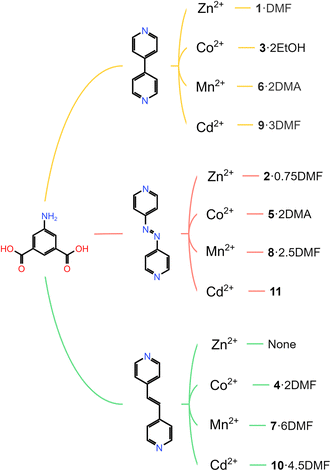 | ||
| Scheme 1 MOF family of 5-aminoisophthtalic acid (H2-5-AIP) and pillaring linkers (top) 4,4′-bipyridyl; (middle) 4,4′-azopyridine and (bottom) 1,2-bis(4-pyridyl)ethylene. | ||
Results and discussion
Zinc complexes
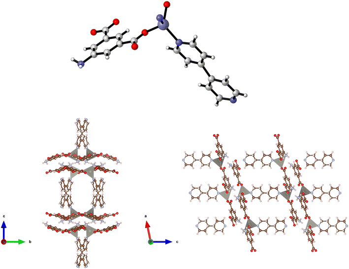
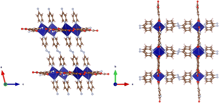
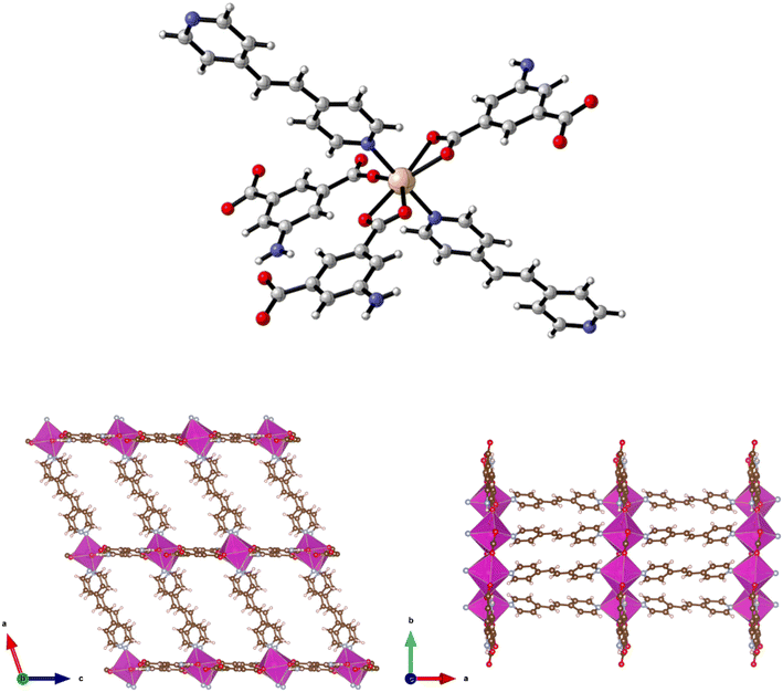
The synthesis of {[Zn(5-AIP)(4,4′-bipy)0.5]·DMF}n (1·DMF) was achieved through the solvothermal reaction of zinc nitrate hexahydrate with H2-5-AIP and 4,4′-bipyridyl in a DMF/MeOH mixture. The resultant colourless, hexagonal prisms were of sufficient quality to perform single crystal X-ray diffraction. Structural elucidation of 1·DMF revealed a hybrid covalent/H-bonded 3-dimensional network bearing the formula {[Zn(5-AIP)(4,4′-bipy)0.5]·DMF}n (1·DMF). In this example, extended 2-D sheets formed by the bridging of three zinc centres by each 5-AIP unit, via monodentate bonds at each carboxylate moiety and an N donor bond from the amino group, are linked into bilayers by 4,4′-bipyridyl units, giving rise to tetrahedral coordination geometry around the zinc centres (Fig. 1, top). Extensive hydrogen bonding observed between the amine hydrogens of each sheet and the non-coordinated carboxylate oxygen of the neighbouring sheet gives the 3-dimensional structure (Fig. 1, bottom).The PLATON squeeze procedure was used to model diffuse electron density in the voids of this framework, giving a total of 301 electrons per unit cell. This corresponds to a total of 8 DMF molecules per unit cell, or 1 per formula unit, which inhabit intersecting 1-dimensional channels situated parallel to the a and c axes, with no bonding interactions observed between the guest molecules and the framework. The binding motif observed here is analogous to the framework reported by Kongshaug et al., namely {[Zn(5-AIP)(4,4′-bipy)0.5]·3H2O}n, isolated from the reaction of H2-5-AIP with 4,4′-bipyridyl and zinc nitrate hexahydrate in a DMF/H2O mixture; however no hydrogen bonding was observed between the bilayers.31 Also reported were the analogous structures {[Zn(5-AIP)(DPE)0.5]·2.5H2O}n, {[Zn(5-AIP)(DPA)0.5]·2.5H2O}n and {[Zn(5-AIP)(DPP)0.5]·3H2O}n (where DPE = 1,2-di-4-pyridyl ethylene, DPA = 1,2-di-4-pyridylethane and DPP = 1,2-di-4-pyridylpropane). It is of particular interest that the use of neutral linkers of increasing length in this example does not have a profound effect on pore size. Due to the fixed orientation of the zinc tetrahedra on opposing walls of the bilayers, the longer dipyridyls are forced to adopt a bent conformation, and while this leads to a minor increase in the size of the small channels running parallel to the a axis, the large channels observed along the b axis exhibited dimensions of 3.5 × 6.7 Å2 in all four examples.
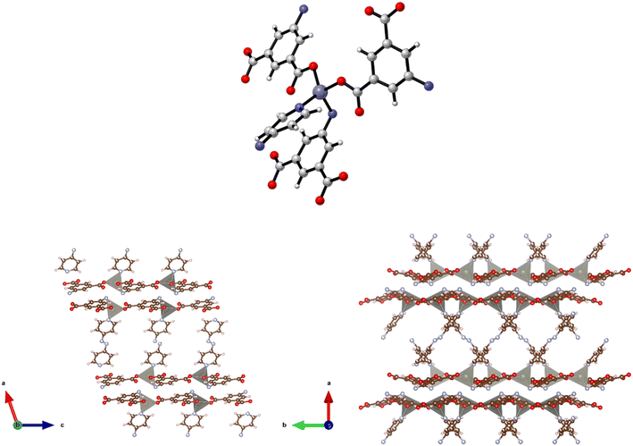
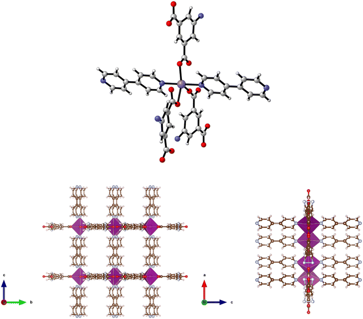
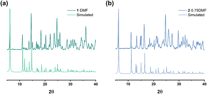
The preparation of {[Zn(5-AIP)(4,4′-azopy)0.5]·0.75DMF}n (2·0.75DMF) was achieved using the same reaction conditions as 1·DMF, but using 4,4′-azopy. Orange prisms suitable for single crystal X-ray diffraction were formed on cooling, however due to a twinning component which could not be resolved the data collected were of sufficient quality to only determine connectivity. Comparison of the collected powder X-ray diffraction pattern for this structure with the simulated pattern for 1 reveals distinct similarities in line spacing and intensity (Fig. 13). TGA and gas adsorption data also show similar behaviours. The framework, bearing the formula {[Zn(5-AIP)(4,4′-azopy)0.5]·0.75DMF}n, exhibits the same binding motif between the zinc centres and the organic linkers as 1·DMF, with tetrahedrally coordinated zinc atoms forming bonds to two carboxylate oxygens from independent 5-AIP molecules, the amine nitrogen of a third 5-AIP molecule, and the pyridinyl nitrogen of a 4,4′-azopy molecule (Fig. 2, top). Each 5-AIP molecule links three zinc centres via the monodentate coordination of each of the carboxylate groups and the amine nitrogen, forming infinite 2-D sheets observed in the b/c plane. The sheets are linked into pairs along the a axis by the coordination of the 4,4′-azopy linker to zinc centres at each of the pyridinyl nitrogen atoms (Fig. 2, bottom, left).
Due to the quality of the data set, the amine hydrogen atoms could not be located, however the proximity of the N(3) atoms to the O(2′) and O(4′) of neighbouring sheets (2.99 Å) offers evidence of strong hydrogen bonding interactions between the bilayer sheets, giving a 3-D hybrid H-bonded/covalent network analogous to that of 1. As with the examples reported by Kongshaug et al.,31 the use of the longer, neutral, pillaring linker has little effect on the size of the large pores, in this example situated parallel to the b axis, with the spacing between the 4,4′-azopy molecule dictated by the distance between the zinc atoms in the [Zn(5-AIP)]n sheets. When viewed along the c axis, however, the narrowing of the small pores by the orientation of the 4,4′-azopy molecules is revealed (Fig. 2, bottom, right). Again, due to the quality of the data set, guest solvent molecules could not be resolved by point atom observations and were modelled as areas of diffuse electron density by the PLATON squeeze procedure, giving 3 DMF molecules located in two small voids per unit cell, equating to 0.75 DMF molecules per formula unit.
Cobalt complexes
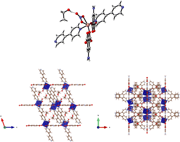
Solvothermal reactions of cobalt nitrate hexahydrate with H2-5-AIP and the bipyridyls 4,4′-bipyridyl (4,4′-bipy) or 4,4′-azopyridine (4,4′-azopy) in a DMF/EtOH mixture afforded two metal organic frameworks of structural formulae {[Co2(NO3)2(5-AIP)(4,4′-bipy)2]·2EtOH}n (3·2EtOH) and {[Co(5-AIP)(DPE)]·3DMF}n (4), respectively. Structure 3·2EtOH was isolated as purple prisms of suitable quality to perform single crystal X-ray diffraction. The structure is comprised of distorted octahedrally coordinated Co2+ ions bound in a monodentate fashion to two carboxylate functions, two pyridinyl nitrogen atoms and a chelating nitrate molecule (Fig. 3, top).Each carboxylate function forms a di-monodentate bridging coordination mode between two crystallographically equivalent Co2+ ions and, unlike the examples previously reported by Wang and co-workers,10 this metal–carboxylate binding motif is observed at both carboxylate functions of the 5-AIP linker, with 180° rotation of successive 5-AIP units giving extended 1-D chains. These chains are linked to their four nearest neighbours through the coordination of 4,4′-bipyridyl units which are approximately parallel to the a axis, but in two different, mutually angled, orientations, giving a herringbone motif and linking the chains into a 3-D structure (Fig. 3, bottom). Chelated nitrate molecules lie out of plane of the 5-AIP units, extending into one dimensional channels with dimensions of 7.08 × 4.18 Å observed parallel to the b axis, with each nitrate unit forming a hydrogen bond to guest ethanol molecules (Fig. 3, bottom, right).
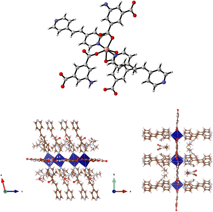
Structure 4·2DMF was also synthesised as purple prisms. However, due to severe and, not fully resolved, twinning problems, the single crystal X-ray diffraction data collected was sufficient only to establish connectivity. The space group for 4·3DMF seems to be P21/c with unit cell: a = 13.726(13), b = 16.881(14), c = 14.234(13), β = 104.396(19) which is consistent with the (pseudo)-isomorphic 5·2DMF, 7·6DMA, and 8·2.5DMF. Similarities observed in the powder X-ray patterns collected for this structure and the related 7 (see below) supported the view that they are isostructural and that the synthesis of the 3-D framework {[Co(5-AIP)(DPE)]·2DMF}n had been successful. This assertion is also supported by the similarities between the TGA data collected for this and the related structures and by elemental analysis. The structure of 4·2DMF is comprised of 6-coordinate, distorted octahedral Co2+ nodes coordinated to a single chelating carboxylate group, two monodentate carboxylate oxygens from different molecules, and two pyridinyl nitrogen atoms (Fig. 4, top).
The 2-D sheets generated by the interaction of the 5-AIP linker with the Co2+ nodes exhibiting the 32 membered macrometallocycles, located in the b/c plane, are the metal–carboxylate binding mechanism observed in this sample. Additionally, the proximity of N to O (2.83 Å) clearly indicates the presence of hydrogen bonding supporting the covalent bonding in this plane. Pillaring DPE linkers extend in the a direction, giving the 3-D structure (Fig. 4, bottom). It is of particular note that the larger void spaces resulting from the use of a longer dipyridyl linker allows the inclusion of larger guest molecules than in 3, with two disordered DMF molecules per formula unit inhabiting intersecting 1-D channels observed parallel to the b and c axes.
Reaction of H2-5-AIP with cobalt nitrate hexahydrate in the presence of 4,4′-azopy in a DMA/EtOH mixture afforded 5·2DMA as dark red prisms of suitable quality for structural elucidation by single crystal X-ray diffraction. This reveals a 3-D MOF of the formula {[Co(5-AIP)(4,4′-azopy)]·2DMA}n which is isostructural with 4·2DMF, bearing the same carboxylate binding motif, with both groups adopting bidentate coordination modes, one chelating to a single cobalt centre and the other exhibiting bridging behaviour between two metal nodes (Fig. 5). As with 4·2DMF, the proximity of the amine nitrogen N(5) to the carboxylate oxygens O(2A) and O(4B) clearly indicates the presence of hydrogen bonding interactions within the Co(5-AIP) sheets.
Coordination of the 4,4′-azopy linker above and below the plane of the Co(5-AIP) sheets gives the extended 3-D structure which bears intersecting channels of 7.47 × 9.80 Å and 3.38 × 9.80 Å observed parallel to the b and c axes respectively (Fig. 6). In the as-synthesised MOF, these channels contain highly disordered DMA molecules. These could not be refined using point atom observations, hence the PLATON squeeze procedure was performed, recovering 399 electrons per unit cell. This equates to 8 DMA molecules per unit cell, or 2 per formula unit.
Manganese complexes
Solvothermal reaction of H2-5-AIP with 4,4′-bipyridyl and Mn(NO3)2·4H2O in a DMA/ethanol mixture afforded yellow prisms of suitable quality for single crystal X-ray diffraction. Structural elucidation revealed an extended 3-D framework of the formula {[Mn(5-AIP)(4,4′-bipy)]·2DMA}n, (6·2DMA), which is isomorphous to the previously described {[Co(5-AIP)(DPE)]·3DMF}n (4·2DMF) and {[Co(5-AIP)(4,4′-azopy)]·2DMA}n (5·2DMA) structures (Fig. 7, top).In this example, the 5-AIP unit links Mn2+ ions in the a/b plane, with 4,4′-bipyridyl units linking these sheets in the c direction. Atoms N(2), C(6), C(7), and C(11) were modelled as disordered across the mirror in the a/b plane (Fig. 6, right). As with 4·2DMF, the proximity of the N(2) atom to O(1′) (2.91 Å) clearly indicates the presence of a hydrogen bonding interaction. Disordered DMA molecules were modelled using the PLATON squeeze procedure which recovered 410 electrons in one large void per unit cell. Given the point atom observations, 8 DMA molecules per unit cell, or two per formula unit, were considered reasonable, located in intersecting channels of 2.67 × 8.21 and 1.38 × 8.21 Å observed along the a and b axes respectively (Fig. 7, bottom).
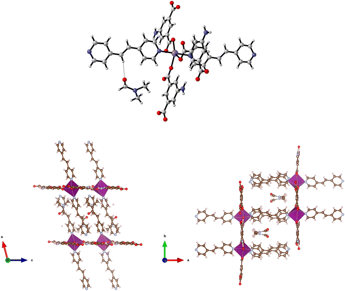
The solvothermal reaction of H2-5-AIP with DPE and Mn(NO3)2·4H2O also afforded yellow prisms of suitable quality for single crystal X-ray diffraction. Structure 7·6DMF is isostructural with 4·2DMF, 5·2DMA, and 6·2DMA with 2-D sheets of Mn(5-AIP) observed in the b/c plane being linked via the dipyridyl unit, giving the structural formula {[Mn(5-AIP)(DPE)]·6DMF}n (Fig. 8, top).
As with 4·2DMF, the use of a longer dipyridyl linker gives rise to the elongation of the pores in the a direction, giving intersecting one dimensional channels of 10.98 × 5.84 and 10.98 × 3.51 Å. As in 4·2DMF, this leads to the incorporation of a greater quantity of guest solvent molecules. A total of six DMF molecules are observed per formula unit. The first of these is well defined, due to the hydrogen bonding interaction of the aldehydic oxygen with the ethylene linkage of the dipyridyl unit and is refined as point atoms; however, the remaining five are disordered and are modelled using the PLATON squeeze procedure as diffuse areas of electron density. As with the other isostructural frameworks, the intersecting 1-D channels containing these guest DMF molecules are visible along the b and c axes (Fig. 8, bottom).
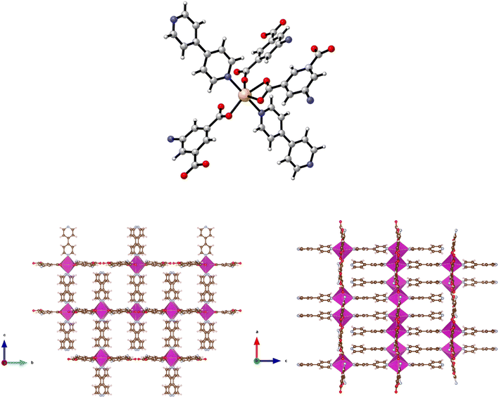
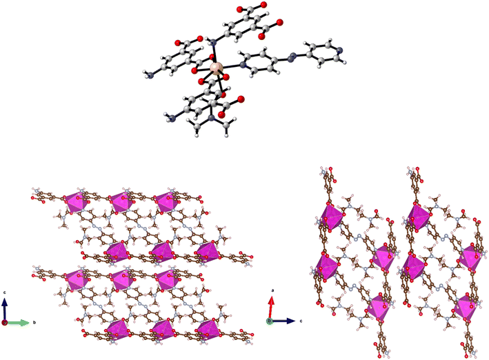
Reaction of H2-5-AIP and 4,4′-azopy with Mn(NO3)2·4H2O under solvothermal conditions also afforded a crystalline solid in good yield. Elemental analyses conducted on samples of the crystals which had been dried by heating to 120 °C under dynamic vacuum for 12 h gave the formula [Mn(5-AIP)(4,4′-azopy)], with the powder X-ray pattern collected for 8, mirroring the pattern simulated for the cobalt analogue of this structure, 5·2DMA, with similar line spacing and intensities observed for both structures. A single crystal X-ray diffraction study revealed a sheet structure in the b/c plane, with the azo ligands forming pillars between these sheets. One carboxylate group bridges pairs of Mn2+ ions, while the other chelates to the metal ion. The sheets are slightly undulating. The sheets are further stabilised by hydrogen bonds from the NH2 group to carboxylate oxygens at 3.18 and 2.95 Å. The DMF solvent of crystallisation lies between the pillars (Fig. 9).
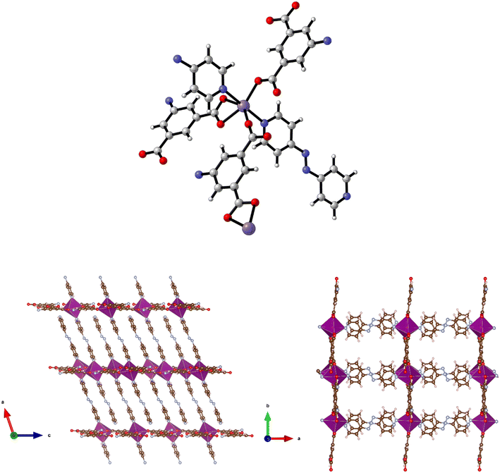 | ||
| Fig. 9 Top: The metal coordination environment in [Mn(5-AIP)(4,4′-azopy)] 8·2.5DMF. Bottom: Diagram of the extended structure of 8·2.5DMF (parallel to the b (left) and c (right) axes). | ||
There is some evidence of slight rocking disorder in the azo pillaring ligand, but this was not modelled as it was not too severe. Point atom analysis suggested 2–3 DMFs, all diffuse and disordered and these were modelled as a diffuse area of electron density by the PLATON squeeze procedure. Squeeze recovered 379 electrons per unit cell. DMF has 40 electrons, so there are approximately 10 DMFs per unit cell, or 2.5 per formula unit, i.e. [Mn(5-AIP)(4,4′-azopy)]·2.5DMF.
Cadmium complexes
Reaction of Cd(NO3)2·4H2O, H2-5-AIP and 4,4′-bipy in DMF/methanol afforded colourless prisms of 9·3DMF. The extended structure of 9·3DMF is formed by the coordination of 4,4′-bipy units in the apical positions of the metal nodes. These neutral linkers, observed parallel to the c axis, link 2-D [Cd(5-AIP)]n sheets into an extended 3-D framework exhibiting intersecting 1-D pores of 3.21 × 8.30 and 3.96 × 8.30 Å (Fig. 10). Badly disordered guest molecules situated inside these pores could not be resolved satisfactorily, however the PLATON squeeze procedure recovered 488 electrons situated in one void per unit cell, situated around the 4,4′-bipy linkers. This data, in conjunction with point atom observations, led to the conclusion that twelve DMF molecules per unit cell, or three per formula unit are present in the as-synthesised framework.The same reaction conditions as in the preparation of 7·6DMF but using cadmium nitrate tetrahydrate led to the isolation of colourless prisms of 10·4.5DMF. Single crystal X-ray diffraction of 10·4.5DMF revealed a related framework to the five described previously. However, minor differences are observed in the coordination modes of the carboxylate groups. In this example, the larger coordination sphere of Cd2+ allows the chelation of carboxylate moieties from two different 5-AIP units to each metal node, with one oxygen atom of each of these units bridging to a second Cd2+ centre. In this manner each metal centre bonds to three 5-AIP units in the a/b plane, with pyridinyl nitrogens bound in the apical positions giving hepta-coordinate metal centres exhibiting distorted pentagonal bipyramidal geometry (Fig. 11). The hydrogen atoms associated with each NH2 group were modelled in geometrically determined positions, and it is clear that these groups are involved in hydrogen bonding with the oxygen atoms of the neighbouring 5-AIP units due to the proximity to the NH2 group at 2.933(7) and 2.988(7) Å.
Solvothermal reaction of H2-5-AIP and 4,4′-azopyridine with Cd(NO3)2·4H2O afforded 11 as red prisms, which were of suitable quality for single crystal X-ray diffraction. Elucidation of the structure revealed very different topology to the frameworks detailed previously. In this example, each Cd2+ node has a pentagonal bipyramidal geometry, coordinating to two chelating carboxylate groups from different molecules and a pyridinyl nitrogen in the pentagonal plane, and to a DMF molecule and an amine nitrogen in the axial plane (Fig. 12, top).
Covalent bonding propagates in the a/c plane, forming bilayer sheets of Cd(5-AIP) linked via the coordinate bonding of the dipyridyl. As with the 3-D hybrid covalent/H-bonded frameworks 1 and 2, significant hydrogen bonding interactions between the bilayer sheets, in this example between the NH2 groups and two carboxylate oxygens, link them into the extended 3-D structure (Fig. 12, bottom). However, unlike the previous examples, there are no large voids filled with disordered solvent. Only one DMF molecule per formula unit is observed in this structure, located in the intersecting 1-D channels of dimensions 3.89 × 6.54 and 3.77 × 7.18 Å extending in the a and b axes, respectively, and acting as a ligand coordinated to the Cd2+ centre via the aldehyde oxygen.
PXRD results
A comparison of simulated and experimental PXRD data for complexes 1–2 is provided in Fig. 13 (3–11 are provided in Fig. S1†). Although the intensity of the peak varies, the majority of the observed results are in accord with their simulated patterns.IR results
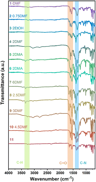
To further investigate the chemical bonding, infrared spectroscopy was performed (Fig. 14). Without the use of a solvent, all complexes were studied at ambient temperature. The bands between 3000 and 3350 cm−1 are ascribed to aromatic C–H stretching vibrations, whilst peaks near 1600 and 1500 cm−1 are attributed to the C![[double bond, length as m-dash]](https://www.rsc.org/images/entities/char_e001.gif) O groups. C–N stretching vibrations of the aromatic amine cause sharp peaks around 1300 cm−1. These IR results are consistent with the above structural analyses.
O groups. C–N stretching vibrations of the aromatic amine cause sharp peaks around 1300 cm−1. These IR results are consistent with the above structural analyses.
SEM results
Under an electron microscope, all of the complexes have various intriguing structures (Fig. 15). Different degrees of agglomeration occur for all complexes, with most exhibiting regular structures. The structures of 1·DMF, 3·2EtOH, and 9·3DMF are chunk-like, whereas the structure of 2·0.75DMF is crisp. MOF 4·2DMF is particle shaped. MOFs 5·2DMA and 10·4.5DMF are rod-like. MOFs 6·2DMA and 7·6DMF exhibit larger, more pronounced, rod-like structures, whilst 8·2.5DMF appears to adopt large, block-like clumps. Lozenge-shaped blocks are adopted by 11. Fig. S3† displays the mapping scanning of 1·DMF, which reveals that the metal is evenly dispersed throughout the complex.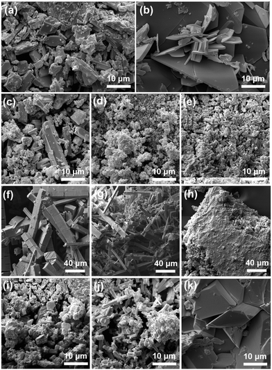 | ||
| Fig. 15 SEM patterns for (a) 1·DMF; (b) 2·0.75DMF; (c) 3·2EtOH; (d) 4·2DMF; (e) 5·2DMA; (f) 6·2DMA; (g) 7·6DMF; (h) 8·2.5DMF; (i) 9·3DMF; (j) 10·4.5DMF; (k) 11. | ||
Ring opening polymerization (ROP) studies
The MOFs herein were screened for their ability to act as catalysts for ring opening polymerization (ROP) of ε-caprolactone (ε-CL) and δ-valerolactone (δ-VL). The MOFs were activated by soaking with chloroform solution for 12 h, and then removing the solution and subsequently drying in a vacuum oven to remove remaining solvent. The activated MOFs are referred to below as catalysts 1–11. Using catalyst 1, the experimental conditions including temperature, solvent, atmosphere (N2 or air), and the ratio of [M]![[thin space (1/6-em)]](https://www.rsc.org/images/entities/char_2009.gif) :
:![[thin space (1/6-em)]](https://www.rsc.org/images/entities/char_2009.gif) [monomer] were optimized. When the ROP was conducted in solvent (normally toluene), all catalysts were inactive. A possible reason is that the solvent molecules occupy the channels in these MOFs and hamper monomer access to the metal sites. Therefore, all MOFs must be activated prior to the ROP procedure and then reacted with the monomer as a melt. Taking catalyst 1 as an example, the optimum conditions were found to be [M]
[monomer] were optimized. When the ROP was conducted in solvent (normally toluene), all catalysts were inactive. A possible reason is that the solvent molecules occupy the channels in these MOFs and hamper monomer access to the metal sites. Therefore, all MOFs must be activated prior to the ROP procedure and then reacted with the monomer as a melt. Taking catalyst 1 as an example, the optimum conditions were found to be [M]![[thin space (1/6-em)]](https://www.rsc.org/images/entities/char_2009.gif) :
:![[thin space (1/6-em)]](https://www.rsc.org/images/entities/char_2009.gif) [monomer] = 1
[monomer] = 1![[thin space (1/6-em)]](https://www.rsc.org/images/entities/char_2009.gif) :
:![[thin space (1/6-em)]](https://www.rsc.org/images/entities/char_2009.gif) 500 at 130 °C over 24 h under air (Table 1, entry 1–7). Note, all catalysts were inactive under nitrogen except for catalyst 1 with δ-VL. Table 1 shows the polymerization with ε-CL under air. Catalysts 1, 2, 6, and 11 revealed activity, with 1, 2, and 11 exhibiting high conversions of >90%. For the system employing catalyst 1, the afforded polycaprolactone (PCL) possessed the highest molecular weight (Mn = 7170 Da), whilst the narrowest molecular weight distribution (PDI = 1.66) was produced using catalyst 2. From the 1H NMR spectra (Fig. 16) of PCL, it was evident that both cyclic and linear polycaprolactone were formed. Similar results were obtained using the other catalysts (Fig. S5–S7, ESI†). The MALDI-TOF mass spectrum of the PCL afforded using catalyst 1 (Table 1, entry 3) is shown in Fig. 17, and peaks can be observed at m/z 6919.963 (n = 60), 7029.731 (n = 61), 7138.872 (n = 63), etc., which correspond to cyclic PCL with Na+ (m/z: 114.14 × n + 22.99). A minor family of peaks corresponds to linear PCL of formula (OH(CL)nH) with Na+ (m/z: 18.00 + 114.14 × n + 22.99). Similar results can be found for the MALDI-TOF mass spectra of the PCL catalyzed using catalysts 2, 6, and 11 (Fig. S8–S10, ESI†).
500 at 130 °C over 24 h under air (Table 1, entry 1–7). Note, all catalysts were inactive under nitrogen except for catalyst 1 with δ-VL. Table 1 shows the polymerization with ε-CL under air. Catalysts 1, 2, 6, and 11 revealed activity, with 1, 2, and 11 exhibiting high conversions of >90%. For the system employing catalyst 1, the afforded polycaprolactone (PCL) possessed the highest molecular weight (Mn = 7170 Da), whilst the narrowest molecular weight distribution (PDI = 1.66) was produced using catalyst 2. From the 1H NMR spectra (Fig. 16) of PCL, it was evident that both cyclic and linear polycaprolactone were formed. Similar results were obtained using the other catalysts (Fig. S5–S7, ESI†). The MALDI-TOF mass spectrum of the PCL afforded using catalyst 1 (Table 1, entry 3) is shown in Fig. 17, and peaks can be observed at m/z 6919.963 (n = 60), 7029.731 (n = 61), 7138.872 (n = 63), etc., which correspond to cyclic PCL with Na+ (m/z: 114.14 × n + 22.99). A minor family of peaks corresponds to linear PCL of formula (OH(CL)nH) with Na+ (m/z: 18.00 + 114.14 × n + 22.99). Similar results can be found for the MALDI-TOF mass spectra of the PCL catalyzed using catalysts 2, 6, and 11 (Fig. S8–S10, ESI†).
| Entry | Catalyst | [M]![[thin space (1/6-em)]](https://www.rsc.org/images/entities/char_2009.gif) : :![[thin space (1/6-em)]](https://www.rsc.org/images/entities/char_2009.gif) [monomer]a [monomer]a |
Temp. (°C) | Conv.b (%) | M n (g mol−1) | PDId |
|---|---|---|---|---|---|---|
| a [M] represents the concentration per metal (M = Zn, Co, Mn, Cd). b Conversion was confirmed by 1H NMR spectroscopy. c GPC analysis in THF at ambient temperature and polystyrene standards were used to calibrate the results (corrected by a factor of 0.56). d Polydispersity index (Mw/Mn) were calculated by GPC. e Time = 12 h. | ||||||
| 1 | 1 | 1![[thin space (1/6-em)]](https://www.rsc.org/images/entities/char_2009.gif) : :![[thin space (1/6-em)]](https://www.rsc.org/images/entities/char_2009.gif) 100 100 |
130 | 57.1 | 12![[thin space (1/6-em)]](https://www.rsc.org/images/entities/char_2009.gif) 470 470 |
1.68 |
| 2 | 1 | 1![[thin space (1/6-em)]](https://www.rsc.org/images/entities/char_2009.gif) : :![[thin space (1/6-em)]](https://www.rsc.org/images/entities/char_2009.gif) 250 250 |
130 | 86.2 | 5150 | 2.46 |
| 3 | 1 | 1![[thin space (1/6-em)]](https://www.rsc.org/images/entities/char_2009.gif) : :![[thin space (1/6-em)]](https://www.rsc.org/images/entities/char_2009.gif) 500 500 |
130 | 97.5 | 7170 | 2.08 |
| 4 | 1 | 1![[thin space (1/6-em)]](https://www.rsc.org/images/entities/char_2009.gif) : :![[thin space (1/6-em)]](https://www.rsc.org/images/entities/char_2009.gif) 750 750 |
130 | 29.9 | 7970 | 2.40 |
| 5 | 1 | 1![[thin space (1/6-em)]](https://www.rsc.org/images/entities/char_2009.gif) : :![[thin space (1/6-em)]](https://www.rsc.org/images/entities/char_2009.gif) 1000 1000 |
130 | 20.2 | 5530 | 1.31 |
| 6e | 1 | 1![[thin space (1/6-em)]](https://www.rsc.org/images/entities/char_2009.gif) : :![[thin space (1/6-em)]](https://www.rsc.org/images/entities/char_2009.gif) 500 500 |
130 | 75.2 | 5950 | 6.16 |
| 7 | 1 | 1![[thin space (1/6-em)]](https://www.rsc.org/images/entities/char_2009.gif) : :![[thin space (1/6-em)]](https://www.rsc.org/images/entities/char_2009.gif) 500 500 |
110 | 32.4 | 17![[thin space (1/6-em)]](https://www.rsc.org/images/entities/char_2009.gif) 940 940 |
1.34 |
| 8 | 2 | 1![[thin space (1/6-em)]](https://www.rsc.org/images/entities/char_2009.gif) : :![[thin space (1/6-em)]](https://www.rsc.org/images/entities/char_2009.gif) 500 500 |
130 | 92.3 | 3760 | 1.66 |
| 9 | 6 | 1![[thin space (1/6-em)]](https://www.rsc.org/images/entities/char_2009.gif) : :![[thin space (1/6-em)]](https://www.rsc.org/images/entities/char_2009.gif) 500 500 |
130 | 60.6 | 6280 | 1.80 |
| 10 | 11 | 1![[thin space (1/6-em)]](https://www.rsc.org/images/entities/char_2009.gif) : :![[thin space (1/6-em)]](https://www.rsc.org/images/entities/char_2009.gif) 500 500 |
130 | 96.9 | 6340 | 2.30 |
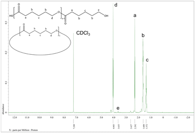 | ||
| Fig. 16 1H NMR spectrum of PCL (Table 1, entry 3). | ||
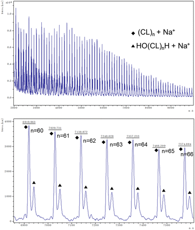 | ||
| Fig. 17 MALDI-TOF mass spectrum of PCL (Table 1, entry 3). | ||
Better results were exhibited for the ROP of δ-VL. All catalysts were active under air, and catalyst 1 was also active under nitrogen. In most cases (except 8), ∼90% or more conversion was achieved, with high molecular weights (Mn = 8200, Table 2, entry 2) and narrow molecular weight distribution (e.g. PDI = 1.31, Table 2, entry 7). End group analysis by 1H NMR spectroscopy revealed similar results to PCL, whereby cyclic PVL (Fig. 18), and other minor PVL families were observed (Fig. S11–S21†). The MALDI-TOF mass spectrum of the PVL obtained using catalyst 1 (Table 2, entry 1) is shown in Fig. 19, and signal peaks can be observed at m/z 6962.644 (n = 69), 7058.687 (n = 70), 7154.559 (n = 71), etc. corresponding to cyclic PVL with Na+ (m/z: 100.12 × n + 22.99). Minor peaks correspond to linear PVL of formula (OH(VL)nH or H3CO(VL)nH) with Na+ (m/z: 18.00 or 32.03 + 100.12 × n + 22.99). Similar results can be found in the MALDI-TOF mass spectra of PVL catalyzed by 1 under nitrogen and catalysts 2–11 under air (Fig. S23–S33†).
| Entry | Catalyst | Atma | Conv.b (%) | M n (g mol−1) | PDId |
|---|---|---|---|---|---|
a All conducted with different ratios [M]![[thin space (1/6-em)]](https://www.rsc.org/images/entities/char_2009.gif) : :![[thin space (1/6-em)]](https://www.rsc.org/images/entities/char_2009.gif) [monomer] in 1 [monomer] in 1![[thin space (1/6-em)]](https://www.rsc.org/images/entities/char_2009.gif) : :![[thin space (1/6-em)]](https://www.rsc.org/images/entities/char_2009.gif) 500, [M] in the ratio means each mol element (Zn, Co, Mn, Cd).
b Conversion was confirmed by 1H NMR spectroscopy.
c GPC analysis in THF at ambient temperature and polystyrene standards were used to calibrate the results (corrected by a factor of 0.58).
d Polydispersity index (Mw/Mn) were calculated by GPC. 500, [M] in the ratio means each mol element (Zn, Co, Mn, Cd).
b Conversion was confirmed by 1H NMR spectroscopy.
c GPC analysis in THF at ambient temperature and polystyrene standards were used to calibrate the results (corrected by a factor of 0.58).
d Polydispersity index (Mw/Mn) were calculated by GPC.
|
|||||
| 1 | 1 | Air | 92.7 | 7940 | 1.99 |
| 2 | 1 | N2 | 92.6 | 8200 | 1.71 |
| 3 | 2 | Air | 94.3 | 4240 | 1.74 |
| 4 | 3 | Air | 97.9 | 5920 | 1.60 |
| 5 | 4 | Air | 92.7 | 4890 | 1.65 |
| 6 | 5 | Air | 90.9 | 5030 | 1.90 |
| 7 | 6 | Air | 99.0 | 4980 | 1.31 |
| 8 | 7 | Air | 89.3 | 5610 | 1.86 |
| 9 | 8 | Air | 19.1 | 2180 | 1.37 |
| 10 | 9 | Air | 99.2 | 7270 | 2.36 |
| 11 | 10 | Air | 98.8 | 5260 | 2.41 |
| 12 | 11 | Air | 92.8 | 5230 | 1.72 |
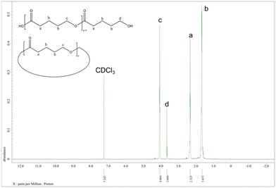 | ||
| Fig. 18 1H NMR spectrum of PVL (Table 2, entry 1). | ||
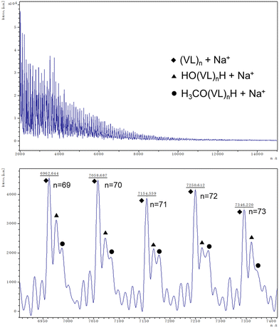 | ||
| Fig. 19 MALDI-TOF mass spectrum of PVL (Table 2, entry 1). | ||
Recyclability studies
Catalyst 1 was employed for the recyclability studies. The catalyst was retrieved from the polymers by washing with dichloromethane using the method reported by Verpoort et al.23 PXRD and IR spectra (Fig. 20) confirm that the catalyst retains its structural integrity after recycling. Table 3 shows catalyst 1 retains high activity (conversion ∼99%), however the PCL product exhibits decreased molecular weight and a wider molecular weight distribution after recycling.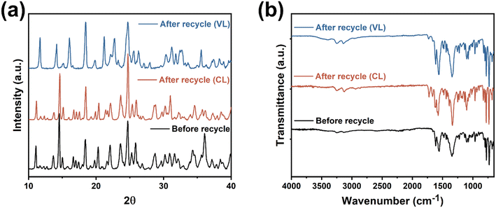 | ||
| Fig. 20 (a) Powder X-ray diffraction and (b) infrared radiation spectra of catalyst 1 before and after 1st recycle. | ||
| Cyclea | Monomer | Conv.b (%) | M n (g mol−1) | PDId |
|---|---|---|---|---|
a All conducted with ratios [Zn2+]![[thin space (1/6-em)]](https://www.rsc.org/images/entities/char_2009.gif) : :![[thin space (1/6-em)]](https://www.rsc.org/images/entities/char_2009.gif) [monomer] of 1 [monomer] of 1![[thin space (1/6-em)]](https://www.rsc.org/images/entities/char_2009.gif) : :![[thin space (1/6-em)]](https://www.rsc.org/images/entities/char_2009.gif) 500.
b Conversion was confirmed by 1H NMR spectroscopy.
c GPC analysis in THF at ambient temperature and polystyrene standards were used to calibrate the results (PCL was corrected by a factor of 0.56, PVL was corrected by a factor of 0.58).
d Polydispersity index (Mw/Mn) were calculated by GPC. 500.
b Conversion was confirmed by 1H NMR spectroscopy.
c GPC analysis in THF at ambient temperature and polystyrene standards were used to calibrate the results (PCL was corrected by a factor of 0.56, PVL was corrected by a factor of 0.58).
d Polydispersity index (Mw/Mn) were calculated by GPC.
|
||||
| 1 | CL | 99.3 | 9850 | 1.89 |
| 2 | CL | 98.4 | 5770 | 2.65 |
| 3 | CL | 98.9 | 5450 | 2.72 |
| 1 | VL | 99.6 | 9640 | 1.95 |
| 2 | VL | 99.4 | 6750 | 2.62 |
| 3 | VL | 99.6 | 5200 | 2.61 |
Kinetics studies
Kinetic studies using catalysts 1, 2, 6, and 11 for the ROP of ε-CL are shown in Fig. S34.† The slope (“b” in the figure) of the linear fit reflects the catalytic rate trend. It is evident that when catalyst 11 is employed as the catalyst for the ROP of ε-CL, the slope is greatest, suggesting that catalyst 11 has the largest rate trend, albeit with a significant induction period. Catalyst 1 exhibits comparable rate trends with catalyst 11, while catalyst 6 is the slowest.According to the slope of the linear plots from the kinetics studies for catalysts 1–11 (Fig. S35†), the rate trend of the ROP with δ-VL is 2 > 5 > 11 > 6 > 4 > 1 (under air) > 3 > 9 > 7 > 10 > 1 (under nitrogen) > 8. The results indicate that catalyst 2 is the best system for the ROP of δ-VL, given it has the highest rate trend and initiates the ROP without an induction period.
It is evident from the results that several catalysts (3–5, 7–10) are inactive in the ROP of ε-CL, but active in the ROP of δ-VL. Fig. S36† gives the structures of ε-CL and δ-VL monomer. It can be clearly seen that δ-VL monomer has a smaller molecular diameter than ε-CL, which will be beneficial in terms of accessing the active metal sites in the MOFs. However, the trend here for more facile ROP of δ-VL versus that of ε-CL, is in contrast to the thermodynamic parameters for these lactones.32
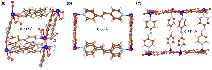
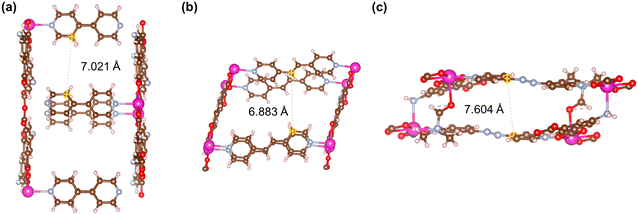
Fig. 21–24 show the repeating cells of catalysts 1–11, the dashed line between the two marked atoms was measured and approximately reflects the inter-pillar distance. It can be observed that those catalysts (3–5, 7–10) that have activities only in ROP with δ-VL have inter-pillar distance less than 7.1 Å. In comparison with other catalysts, catalyst 2 has the largest repeating cell inter-pillar distance (Fig. 21(b)). Therefore, catalyst 2 showed excellent performance both in ROP with ε-CL and δ-VL. By comparing the repeating cell inter-pillar distance of catalyst 3 (Fig. 22(a)) and 8 (Fig. 23(c)), despite having a smaller inter-pillar distance than catalyst 8, catalyst 3 exhibited higher conversion (Table 2) and rate trend (Fig. S35†). It could be attributed to the differences between the cobalt (catalyst 3) and manganese (catalyst 8) atoms.
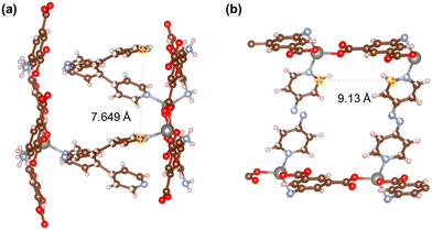 | ||
| Fig. 21 Repeating cells (each repeating cell in MOFs creates the topological structure, the repeating cells displayed here are without solvent molecules) of catalysts (a) 1 and (b) 2. | ||
Conclusion
In conclusion, eleven 2- and 3-D MOFs have been synthesised using the solvothermal reaction of 5-aminoisophthalic acid with the nitrates of zinc, cobalt, manganese, and cadmium in the presence of the neutral pillaring linkers 4,4′-bipyridyl, 4,4′-azopyridine, and 1,2-bis(4-pyridyl)ethylene. The MOFs have been structurally characterised, and their ability to act as catalysts for the ROP of ε-CL and δ-VL investigated. Only selected MOFs are active in the ROP of ε-CL, whereas all exhibit activity in the ROP of δ-VL. We tentatively attribute the differences in activity to steric hindrance. By measuring the inter-pillar distance of the repeat units of catalysts 1–11, it can be concluded that a inter-pillar distance greater than 7.2 Å is favourable for the ROP of ε-CL. Other factors are also at play, and the results suggest that for these 11 catalysts the ROP behaviour is influenced by both the metal ions present and the pore size of the repeat unit. Cyclic and linear PCL and PVL were identified by 1H NMR spectra and MALDI-TOF mass spectra. A kinetics study revealed the rate trend of the MOFs during catalysis. Catalyst 11{Cd(5-AIP)(4,4′-azopy)(DMF)}n in ROP of ε-CL and catalyst 2{[Zn(5-AIP)(4,4′-azopy)0.5]·DMF}n in ROP of δ-VL performed best. It is interesting to note that catalyst 1{[Zn(5-AIP)(4,4′-bipy)0.5]·DMF}n is active for the ROP of δ-VL whether under nitrogen or air.Conflicts of interest
There are no conflicts of interest to declare.Acknowledgements
The China Scholarship Council (CSC) is thanked for financial support to Yi Gong. We thank the UK National Crystallographic Service at Southampton for data collection on compounds 1·DMF, 2·0.75DMF, 4·2DMF and 10·4.5DMF. Dr. Martin J Taylor is thanked for helping with the BET data collection.References
- A. Dhakshinamoorthy, A. M. Asiri and H. Garcia, Catal. Sci. Technol., 2016, 6, 5238–5261 RSC.
- C. Shan, X. Zhang, S. Ma, X. Xia, Y. Shi and J. Yang, Colloids Surf., A, 2022, 636, 128108 CrossRef CAS.
- O. G. Nik, X. Y. Chen and S. Kaliaguine, J. Membr. Sci., 2012, 413–414, 48–61 CrossRef CAS.
- X. Gao, S. S. Zhang, H. Yan, Y. W. Li, Q. Y. Liu, X. P. Wang, C. H. Tung, H. Y. Ma and D. Sun, CrystEngComm, 2018, 20, 4905–4909 RSC.
- T. Fukushima, S. Horike, Y. Inubushi, K. Nakagawa, Y. Kubota, M. Takata and S. Kitagawa, Angew. Chem., Int. Ed., 2010, 49, 4820–4824 CrossRef CAS PubMed.
- A. Husain, P. Rani, Alisha, A. Sharma, T. Mondal, S. K. Saha, K. K. Bhasin, M. Trivedi and G. Kumar, CrystEngComm, 2020, 22, 5980–5986 RSC.
- N. K. Gupta, S. Kim, J. Bae and K. S. Kim, Chem. Eng. J., 2021, 411, 128536 CrossRef CAS.
- Y. Q. Chen, C. Cao, Y. Tian, S. J. Liu, X. Y. Qu, X. Z. Zhang, Q. Gao and M. Zhong, J. Solid State Chem., 2020, 286, 121314 CrossRef CAS.
- A. Chinthamreddy, R. Karreddula, G. K. Pitchika and M. S. SurendraBabu, J. Inorg. Organomet. Polym. Mater., 2021, 31, 1381–1394 CrossRef CAS.
- L. Wang, Y. Liu, J. Zhang and Y. Xia, Inorg. Nano-Met. Chem., 2020, 50, 1234–1238 CrossRef CAS.
- S. Ghosh, A. Sarkar, S. Chatterjee and H. P. Nayek, J. Solid State Chem., 2021, 296, 121929 CrossRef CAS.
- H. G. Jin, Y. Z. Yan, J. Li, Z. G. Gu, J. H. Chen, Y. T. Liu, Z. P. Zheng, Q. G. Zhan and Y. P. Cai, Inorg. Chem. Commun., 2012, 23, 25–30 CrossRef CAS.
- L. F. Song, C. H. Jiang, C. L. Jiao, J. Zhang, L. X. Sun, F. Xu, W. S. You, Z. G. Wang and J. J. Zhao, Cryst. Growth Des., 2010, 10, 5020–5023 CrossRef CAS.
- Z. P. Deng, Z. Y. Zhang, L. H. Huo, S. W. Ng, H. Zhao and S. Gao, CrystEngComm, 2012, 14, 6548–6558 RSC.
- Y. J. Hsieh, C. Zou, J. J. Chen, L. C. Lin and D. Y. Kang, Microporous Mesoporous Mater., 2021, 326, 111344 CrossRef CAS.
- Y. Chen, H. Wu, Y. Yuan, D. Lv, Z. Qiao, D. An, X. Wu, H. Liang, Z. Li and Q. Xia, Chem. Eng. J., 2020, 385, 123836 CrossRef CAS.
- N. Zhao, F. Sun, P. Li, X. Mu and G. Zhu, Inorg. Chem., 2017, 56, 6938–6942 CrossRef CAS PubMed.
- M. Y. Kan, J. H. Shin, C. T. Yang, C. K. Chang, L. W. Lee, B. H. Chen, K. L. Lu, J. S. Lee, L. C. Lin and D. Y. Kang, Chem. Mater., 2019, 31, 7666–7677 CrossRef CAS.
- T. Xing, M. R. J. Elsegood, S. H. Dale and C. Redshaw, Catalysts, 2021, 11, 1554–1573 CrossRef CAS.
- X. Zhang, K. Chen, M. Chicoma, K. Goins, T. J. Prior, T. A. Nile and C. Redshaw, Catalysts, 2021, 11, 1–19 CrossRef CAS.
- K. Wang, T. J. Prior and C. Redshaw, Chem. Commun., 2019, 55, 11279–11282 RSC.
- C. J. Chuck, M. G. Davidson, M. D. Jones, G. Kociok-Köhn, M. D. Lunn and S. Wu, Inorg. Chem., 2006, 45, 6595–6597 CrossRef CAS.
- F. Naz, M. Ciprian, B. Mousavi, S. Chaemchuen, M. Zhu, S. Yan and F. Verpoort, Eur. Polym. J., 2021, 142, 110127 CrossRef CAS.
- R. M. Abdur, B. Mousavi, H. M. Shahadat, N. Akther, Z. Luo, S. Zhuiykov and F. Verpoort, New J. Chem., 2021, 45, 11313–11316 RSC.
- W. G. Cui, G. Y. Zhang, T. L. Hu and X. H. Bu, Coord. Chem. Rev., 2019, 387, 79–120 CrossRef CAS.
- A. Tombesi and C. Pettinari, Inorganics, 2021, 9, 81–110 CrossRef CAS.
- F. Naz, F. Mumtaz, S. Chaemchuen and F. Verpoort, Catal. Lett., 2019, 149, 2132–2141 CrossRef CAS.
- O. Kholdeeva and N. Maksimchuk, Catalysts, 2021, 11, 1–23 CrossRef.
- A. Alzamly, M. Bakiro, S. Hussein Ahmed, L. A. Siddig and H. L. Nguyen, Coord. Chem. Rev., 2022, 462, 214522 CrossRef CAS.
- Y. Qin, X. Han, Y. Li, A. Han, W. Liu, H. Xu and J. Liu, ACS Catal., 2020, 10, 5973–5978 CrossRef CAS.
- K. O. Kongshaug and H. Fjellvåg, Inorg. Chem., 2006, 45, 2424–2429 CrossRef CAS.
- See Handbook of Ring Opening Polymerization, ed. P. Dubois, O. Coulembier and J.-M. Raquez, Wiley-VCH, 2009 Search PubMed.
Footnote |
| † Electronic supplementary information (ESI) available. CCDC 2207267–2207277. For ESI and crystallographic data in CIF or other electronic format see DOI: https://doi.org/10.1039/d2ce01317g |
| This journal is © The Royal Society of Chemistry 2023 |

