 Open Access Article
Creative Commons Attribution 3.0 Unported Licence
Optothermal rotation of micro-/nano-objects
Hongru
Ding
 a,
Zhihan
Chen
b,
Carolina
Ponce
a and
Yuebing
Zheng
 *ab
*ab
aWalker Department of Mechanical Engineering, The University of Texas at Austin, Austin, TX 78712, USA
bMaterials Science & Engineering Program and Texas Materials Institute, The University of Texas at Austin, Austin, TX 78712, USA. E-mail: zheng@austin.utexas.edu
First published on 25th January 2023
Abstract
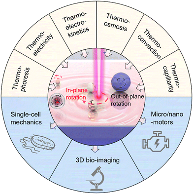
Due to its contactless and fuel-free operation, optical rotation of micro-/nano-objects provides tremendous opportunities for cellular biology, three-dimensional (3D) imaging, and micro/nanorobotics. However, complex optics, extremely high operational power, and the applicability to limited objects restrict the broader use of optical rotation techniques. This Feature Article focuses on a rapidly emerging class of optical rotation techniques, termed optothermal rotation. Based on light-mediated thermal phenomena, optothermal rotation techniques overcome the bottlenecks of conventional optical rotation by enabling versatile rotary control of arbitrary objects with simpler optics using lower powers. We start with the fundamental thermal phenomena and concepts: thermophoresis, thermoelectricity, thermo-electrokinetics, thermo-osmosis, thermal convection, thermo-capillarity, and photophoresis. Then, we highlight various optothermal rotation techniques, categorizing them based on their rotation modes (i.e., in-plane and out-of-plane rotation) and the thermal phenomena involved. Next, we explore the potential applications of these optothermal manipulation techniques in areas such as single-cell mechanics, 3D bio-imaging, and micro/nanomotors. We conclude the Feature Article with our insights on the operating guidelines, existing challenges, and future directions of optothermal rotation.
1. Introduction
Awarded the Nobel Prize in Physics 2018, optical tweezers have proved to be an effective instrument for non-contact spatial manipulation of micro/nanoparticles as well as living biological samples.1–8 On the basis of optical tweezers, various optical rotation platforms have been developed for exquisite control of micro/nanoscale targets over their rotational degrees of freedom using light (e.g., laser beams).9–11 The light-powered rotation, termed optical rotation, holds significant application potential in nano-torque sensing,12–14 nanosurgery,15,16 micro/nanofluidic systems,17,18 and so on. To achieve optical rotation, a dynamic intensity profile,19,20 nonlinear polarization,12,21,22 optical angular momenta,23,24 or radiation pressure25 is typically utilized to produce asymmetric light-matter interactions for the generation of optical torques. In addition, sophisticated designs are also required on the rotating targets, which typically possess on-demand geometry, optical birefringence, or specific compositions.26–29 The rigorous requirements for light beams and properties of particles largely restrict the broader applications of optical rotation. Moreover, the optical rotation of nanoparticles is extremely challenging as optical forces and torques decrease substantially with particle size.6 Though high-power light beams can be used for rotation at the nanoscale level, the resultant optical heating will lead to strong Brownian motions that significantly reduce the frequency stability of the rotation.30To overcome the bottlenecks of complex optics, limited applicability, and heat-induced instability of optical rotation, heat-mediated optical rotation, i.e., optothermal rotation, has been developed for rotary control of micro-/nano-objects by leveraging optical heating to generate thermal forces and torques. Over the past two decades, researchers have established multiple theories to describe the translational migration of colloids and living objects under temperature gradient fields.31–36 Consequently, different optothermal manipulation techniques have been developed,37–52 leading to applications in nanofabrication,53–58 chemical and biological sensing,59–61 and cargo delivery.62,63 Based on this, optothermal rotation has been further developed recently for precise and versatile rotations of colloidal particles and living cells with striking advantages such as low operation power, high applicability, and long working distance. Through the synergy of diverse light-induced thermal forces and/or optical forces, researchers, including us, manage to rotate objects of diverse sizes, materials, and shapes with low-power laser beams and simple optics for the growing demands in sophisticated biological measurements, imaging, and the development of nano-engines. This Feature Article focuses on the development of the optothermal rotation of micro/nanoscale objects in liquids (Fig. 1). We first introduce the fundamentals of different thermal forces that can drive stable optothermal rotation. Then, different approaches to achieving in-plane and out-of-plane rotation in respect of the substrates are reviewed based on their working mechanisms and various potential applications. Finally, we provide our perspectives on existing challenges and future directions of optothermal rotation.
2. Fundamental mechanisms
Different physical mechanisms for optothermal rotation in liquids are introduced in this section, including thermophoresis, thermoelectricity, thermo-electrokinetics, thermo-osmosis, thermal convection, and thermo-capillarity. The thermal forces originating from those optothermal phenomena are employed to control the translational movements of the targets and drive their stable rotation.2.1. Thermophoresis
Thermophoresis (also known as thermodiffusion or the Soret effect) is defined as the directed migration of tiny particles (e.g., ions, molecules, and colloidal particles) along a temperature gradient in liquids.64–67 The temperature gradient functions as a general force that directs the suspended particles to a cold or warm region at a certain velocity given by| u = DT∇T | (1) |
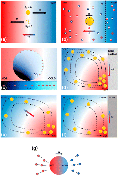 | ||
| Fig. 2 Schematics of physical mechanisms for heat-mediated optical manipulation: (a) thermophoresis, (b) thermoelectricity, (c) thermo-electrokinetics, (d) thermo-osmosis, (e) thermal convection, (f) thermo-capillarity, and (g) photophoresis. Adapted with permission.37 Copyright 2022, American Chemical Society. | ||
2.2. Thermoelectricity
Liquid thermoelectricity describes the generation of an electric field, i.e., a thermoelectric field, from the charge separation of ions in electrolyte solutions under a temperature field (Fig. 2b).38 In a thermal equilibrium state, cations couple with anions due to electrostatic interactions. While in a non-equilibrium state, a thermal gradient drives cations and anions with different speeds and directions, depending on the ions’ size and solvation energy.68 Additionally, the diffusion of molecules with high polarity (e.g., water) under a certain temperature can also lead to nanoscale separation of atoms with different electronegativity.69 These spatially separated charges (ions and atoms with partial charges) lead to a bulk thermoelectric field given by | (2) |
2.3. Thermo-electrokinetics
In analogy with optical electrokinetics, where the migration of colloids is induced by the non-uniform electric field based on a photoconductive substrate,70,71 thermo-electrokinetics describes a similar electrokinetic (EK) migration that stems from the electric fields from the temperature-responsive substrates (Fig. 2c).44,72 Most colloids are negatively charged due to their ionized acid groups on the surface.31 Similarly, substrates can carry surface charges by coating a thin layer of acid groups (e.g., carboxylic acids). In particular, the decrease of the temperature generally promotes the dissociation of the acid molecules (e.g., COO− and H+) according to the Van’t Hoff equation.73,74 Therefore, the surface-charge gradients of colloids and substrates can be tuned by the temperature field, which leads to an EK torque that can power the rotation of the colloids. The EK force is given by | (3) |
2.4. Thermo-osmosis
Thermo-osmosis describes the flow parallel with a surface under a temperature gradient, which is typically directed toward higher temperature regions (Fig. 2d). Specifically, excess hydrostatic pressure can be induced by a temperature gradient within an electric double layer near the surface. The gradient of the hydrostatic pressure is opposite to the temperature gradient and leads to a creeping flow parallel to the surface. Thus, when a colloidal particle stays in a temperature field, the force from the thermo-osmotic flow drives the particle moving in the opposite direction of the flow at the velocity31 | (4) |
2.5. Thermal convection
Thermal convection, known as natural convection, results from buoyance forces exerting on fluids with heat-induced density variations.77 Like the violent vibration of atoms in solids at high temperatures,78,79 fluid molecules scatter and separate in the vicinity of a hot spot, causing the fluid to be less dense. Due to buoyance forces, the less-dense fluid moves upward, and the cooler fluid gets denser and sinks (Fig. 2e). Meanwhile, the surrounding fluid moves toward the hot spot due to fluid continuity. Thermal convection is typically bulky and not suitable for single-particle manipulation. Therefore, optical heating upon laser illumination on light-absorbing nanostructures has been proposed to achieve localized temperature gradient fields for accurate control of thermal convection flows and delicate micro/nano-manipulation.80,812.6. Thermo-capillarity
Thermo-capillary flow is one type of Marangoni effect: mass transfer along a fluid–fluid interface happens due to the gradient of surface tension (Fig. 2f). Surface tension can be tuned by concentration, temperature, and electrical potential. The cool liquid that has a high surface tension can pull the surrounding warmer liquid that has a lower surface tension. This leads to a thermo-capillary flow, whose velocity is given by | (5) |
2.7. Photophoresis
Under illumination, directed movement of light-absorbing particles suspended in gas is referred to as photophoresis, which is caused by the interactions between the particles and the surrounding molecules. For instance, the asymmetric optical heating of a particle generates a non-uniform temperature field, where distinct forces from molecules in the cold and hot sides lead to a net force that drives the particle towards or away from the beam (Fig. 2g).88,89 Additionally, for a particle of a uniform temperature, its thermal accommodation coefficient difference can also induce photophoretic movements.903. Optothermal rotation techniques
Different applications of optothermal rotation are demonstrated with rational management of light, heat, and solutions in optothermal fluidic systems. This Feature Article focuses on the contributions of the Zheng Research Group to the recent progress in optothermal rotation. According to the relationship between the rotation axis and substrate, optothermal rotation can be classified into in-plane optothermal rotation and out-of-plane optothermal rotation, which both lead to different types of applications and are discussed separately in this section.3.1. In-plane rotation
To fill this gap, we have developed opto-thermophoretic platforms for both rotational and translational manipulation of synthesized and biological cells.49,96 The working principle of our platforms is illustrated in Fig. 3a. First, a real-time tailorable and reconfigurable temperature field is established upon the illumination of a laser beam on a uniform light-absorbing substrate (Fig. 3a(i)). Since the alignment of solvent molecules at the liquid-particle interface depends on the surrounding temperature (Fig. 3a(ii)), a gradient of interfacial entropy is then generated under the light-generated temperature field. According to Anderson's model, the entropy gradient causes an interfacial slip flow that exerts a thermophoretic force on the particle's surface.97 The thermophoretic velocity is given by32
 | (6) |
![[thin space (1/6-em)]](https://www.rsc.org/images/entities/char_2009.gif) ln
ln![[thin space (1/6-em)]](https://www.rsc.org/images/entities/char_2009.gif) ε/∂
ε/∂![[thin space (1/6-em)]](https://www.rsc.org/images/entities/char_2009.gif) ln
ln![[thin space (1/6-em)]](https://www.rsc.org/images/entities/char_2009.gif) T, is a function of interfacial entropy and the key for the modulation of opto-thermophoretic movement. For instance, we achieved on-demand opto-thermophoretic trapping of 1 μm polystyrene (PS) spheres in water as illustrated by Fig. 3a(iii).
T, is a function of interfacial entropy and the key for the modulation of opto-thermophoretic movement. For instance, we achieved on-demand opto-thermophoretic trapping of 1 μm polystyrene (PS) spheres in water as illustrated by Fig. 3a(iii).
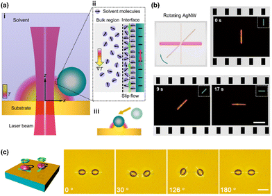 | ||
| Fig. 3 Opto-thermophoretic rotation techniques. (a) Working principle of opto-thermophoretic manipulation of colloids. (b) Opto-thermophoretic rotation of a silver nanowire by a thermoplasmon with a 532 nm laser beam. (c) Opto-thermophoretic rotation of two live yeast cells in water with two line-shaped laser beams at the wavelength of 532 nm. The light-absorbing substrate is the same as (b). Scale bars: (b) 5 μm and (c) 10 μm. (a and b) Adapted with permission.49 Copyright 2018, American Chemical Society. (c) Adapted with permission.96 Copyright 2017, American Chemical Society. | ||
The rotation of micro/nanoscale colloids can be achieved on this platform through geometric design and dynamic control of opto-thermophoretic potentials for torque generation. The optical rotation of metallic anisotropic nanoparticles has been achieved by exploiting optically aligning torque produced by laser beams with rotating linear polarization.9 A similar opto-thermophoretic aligning torque can be achieved by reshaping and steering the laser beams. Comprehensively, a line-shape beam spot can be obtained through the digital micromirror device (DMD), which leads to a line-shape opto-thermophoretic potential. This anisotropic potential can then capture anisotropic micro-/nano-objects at the beam spot and rotate them until the status of minimum energy is reached. By rotating the line-shape beam spot, a rotary anisotropic opto-thermophoretic potential well can be obtained, which continuously rotates targets through the dynamic minimum-energy status. As shown in Fig. 3b, a sliver (Ag) nanowire (12 μm × 100 nm) is rotated in isopropyl alcohol (IPA) by a rotary one-dimensional (1D) beam spot,49 where the offset between the position of the Ag nanowire and the minimum-energy position leads to a trapping torque. In addition to the synthesized particles, we have also achieved the rotation of live biological cells.96 In water, parallel rotation of two yeast cells at an angular resolution of one degree has been demonstrated (Fig. 3c). Moreover, our platform enables the rotation of bacteria such as Escherichia coli.
Compared with other optical rotation techniques, opto-thermophoretic rotation has shown its versatility in the dynamic rotation of low-dimensional objects of diverse sizes and materials using a single low-power beam. In addition, the opto-thermophoretic torque is not dictated by the refractive index contrast between the targets and surroundings, which is superior to traditional optical tweezers.
We have further extended the concept of opto-thermoelectric tweezers to an opto-thermoelectric rotation (Fig. 4a).98 To achieve the rotation, a self-sustained thermoelectric field should be established on target particles based on their non-uniform light-absorbing structures (e.g., particles with half-coated metal). Due to the significant difference in light absorption between the metal cap and the intrinsic part, a non-uniform temperature field is established in the vicinity of the particle under illumination (Fig. 4b). Accordingly, a thermoelectric field is produced from the separation between CTAC micelles and Cl− ions around the particle, which then impose the thermoelectric force to the particle. The interplay among the thermoelectric force, optical force, and Stokes drag force (Fig. 4c) leads to a torque that drives the orbiting movements of the particle (Fig. 4d and 4e). A high rotation rate of 80 rpm can be obtained by simply increasing the optical power to 3.2 mW for a higher thermoelectric field (Fig. 4f).
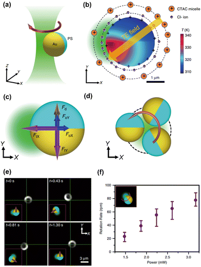 | ||
| Fig. 4 The opto-thermoelectric rotation technique. (a) 3D schematic illustration of an orbiting metal-coated Janus particle driven by a laser beam. (b) Simulated temperature distribution of a 2.7 μm Au/PS Janus particle under the illumination of a 532 nm beam at a power of 2 mW. The distribution of ions and the established thermoelectric field are illustrated as well. The orange and blue solid circles represent the CTAC micelles and Cl− ions, respectively. The orange arrow denotes the direction of the thermoelectric field. (c) Schematics of the thermoelectric force (purple), optical force (blue), and drag force (brown) acting on the Janus particle. (d) Two-dimensional (2D) schematics of the orbital movements of the particle powered by the beam. (e) Time-resolved dark-field images of the rotation of the Janus particle. (f) The measured rotation rate as a function of the optical power of the beam. Adapted with permission.98 Copyright 2020, Springer Nature. | ||
Furthermore, opto-thermoelectric swimmers are developed on the same platform, where rotary control with thermoelectric fields is utilized to achieve delicate control of swimming directions. Specifically, if the laser beam is switched for particle rotation to another loosely focused beam, the thermoelectric torque can be turned into a thermoelectric force pointing from the PS hemisphere to the Au hemisphere to induce the translational motion of the particle. Through the on-demand switch between two lasers, actively navigated swimming can be demonstrated by alternatively changing the propulsion and rotation states of the particles with a feedback control system. With the capability to control particles over all degrees of freedom in an automatic manner, opto-thermoelectric swimmers are foreseen to open novel horizons in micro/nanorobotics.
Recently, we have achieved stable and fast in-plane rotation of sub-100 nm light-absorbing particles via opto-thermocapillary forces (Fig. 5a).107 The key to opto-thermocapillary manipulation is the thin layer of polymers on the substrate, which can be selectively turned into a quasi-liquid phase upon laser irradiation and lead to thermocapillary flow.108 In this work, a solid layer of CTAC is placed between a glass substrate and 80 nm gold nanoparticles (AuNPs). Upon the illumination of a 660 nm laser beam on the AuNP, a localized phase transition of CTAC is triggered by the optical heating of the particle. As shown in Fig. 5b (top), a maximum temperature of 593.4 K is obtained on the illuminated AuNP at the optical power of 10 mW. A very thin layer of CTAC in the vicinity of the AuNP (<15 nm) is then heated above its phase transition temperature (505–510 K). Therefore, a localized liquid-air interface is formed around the illuminated particle. Owing to the multifaceted asymmetry of the AuNP, a temperature gradient exists at the liquid/air interface contacting the AuNP. Meanwhile, thermocapillary stress was generated on the particle's surface because of the interfacial surface tension gradient, with dγ/dT ∼ −0.097 mN m−1K−1. A considerable tangential opto-thermocapillary force can then be obtained to trigger an in-plane rotation (Fig. 5c), while the synergy of the capillary forces and optical forces maintains the stable orbital movements (Fig. 5d). Fig. 5e shows the real-time rotation of an 80 nm AuNP under laser excitation, whose statistic displacement results (Fig. 5f) indicate that the AuNP rotates stably in a circular orbit about the laser beam.
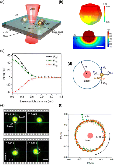 | ||
| Fig. 5 The opto-thermocapillary rotation technique. (a) 3D schematic illustration of an orbiting light-absorbing nanoparticle driven by a laser beam. (b) Top: Simulated 3D temperature distribution of an 80 nm AuNP under the illumination of a 660 nm beam at a power of 10 mW. Bottom: Simulated 2D temperature distribution of the CTAC film near the AuNP. Scale bar: 50 nm. (c) Simulated thermocapillary force (black squares) acting on the AuNP. The tangential and radial components of the force are denoted by red triangles and green circles, respectively. (d) Schematics of the thermocapillary force, optical force, and drag force acting on the AuNP particle. (e) Time-resolved dark-field optical images of an orbiting 80 nm AuNP. Optical power: 6 mW. Scale bar: 1 μm. (f) Centroid tracking of the rotating AuNP. Adapted with permission.107 Copyright 2022, American Chemical Society. | ||
This opto-thermocapillary rotation platform may open a novel path toward nanomachines. Contrary to other existing light-powered machines, our nanomachines have suppressed Brownian motion and could serve as fuel-free and gear-free engines to convert optical energy into mechanical work for various nano-electro-mechanical systems.
3.2. Out-of-plane rotation
Optothermal rotation techniques that enable out-of-plane micro/nanorotation (i.e., rotation of an object around an axis parallel to the substrate) are featured in this section. Compared to in-plane rotation, out-of-plane rotation finds a variety of unique applications in fields such as single-cell mechanics, 3D bio-imaging, and micro-/nano-surgery.16,109–115 However, out-of-plane rotation is known to be more challenging to accomplish especially for highly symmetric or isotropic targets.116 In the past five years, a few groups have proposed diverse strategies for out-of-plane rotation under broken symmetries generated in light-driven temperature fields.44,72,75,117–120To overcome these obstacles, we propose a universal rotation strategy based on opto-thermo-electrokinetic coupling, which enables the out-of-plane rotation of particles with diverse sizes, materials, and shapes using low-power and simple optics.72 The working principle of opto-thermo-electrokinetic rotation is illustrated in Fig. 6a. The particles and substrate are immersed in a solution containing polyethylene glycol (PEG) and phosphate-buffered saline (PBS). A single laser beam is used to create a local temperature field between the charged particle and a light-absorbing substrate with carboxylic acid-terminated alkanethiol self-assembled monolayers. Under the temperature gradient, all the ions and molecules diffuse from the hot to the cold region, leading to the charge separation of Na+ and Cl− ions, and the concentration gradient of PEG molecules (Fig. 6b). Moreover, the temperature gradient leads to the dissociation of acid functional groups on the substrate's and particle's surfaces (Fig. 6c),73,74 which results in the gradients of surface charge, respectively (Fig. 6d). Accordingly, the charge separation of Na+ and Cl− ions leads to a thermoelectric field, which exerts a repulsive thermoelectric force on the particle. Meanwhile, the concentration gradient of the PEG molecule results in an attractive depletion force to trap the particle around the laser beam.43,124 More importantly, the electrokinetic interaction between the surfaces of the particle and the substrate generates an accumulative force with the line of action not passing through the particle's centroid, which imposes a torque on the particle with the axis parallel to the substrate and finally drives its out-of-plane rotation. Under the illumination of a lower-power 532 nm beam, a 2.8 μm PS microsphere in a 5% PEG/5% PBS solution rotates in an out-of-plane manner at the rate of 32.0 rpm (Fig. 6e). The two bright spots are fluorescent nanobeads attached to the particle for the observation of out-of-plane rotation. In contrast to other optical rotation systems where the laser directly illuminates onto the object, the laser beam in our system can be positioned away from the rotary objects to reduce the optical damage.
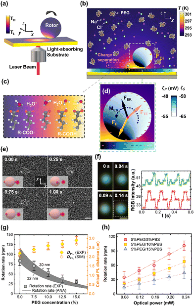 | ||
| Fig. 6 The opto-thermo-electrokinetic rotation technique. (a) 3D schematic illustration of the experimental setup. (b) Simulated 2D temperature distributions of the rotor, substrate, and surrounding liquid. Yellow arrows indicate discrete depletion forces on the rotor. (c) The temperature effect on the dissociation of carboxylic function groups. (d) Schematics of optothermal forces and torque on the rotor. The yellow, red, and black arrows denote the depletion, thermoelectric, and thermo-electrokinetic forces, respectively. A net torque (black curved arrow) can be generated on the particle at a certain position where a balance is reached among the three forces. The temperature-dependent distributions of negative charges on the surface of the particle and substrate are indicated by the “−” symbols. (e) Time-resolved fluorescent images of out-of-plane rotary 2.8 μm PS particles. Optical power: 78.4 μW. Scale bar: 2 μm. (f) Left: Real-time dark-field optical images of a rotating 300 nm PS/Au Janus particle. Right: Red-green-blue (RGB) intensity extracted from the dark-field optical images of the Janus particle. The white dashed rectangle in the left figure marks the selected area from which the RGB intensity is recorded. (g) Rotation rate and laser-particle distance (DP−L) of a 2.8 μm PS particle versus PEG concentration in 5% PBS solutions at an optical power of 196 μW. The grey squares and black lines are experimentally measured (indicated as “EXP”) and analytic (indicated as “ANA”) rotation rates, respectively. The gray region represents the rotation rates calculated as the particle-substrate gap ranges from 30 to 32 nm. The yellow diamonds and circles are measured and simulated (indicated as “SIM”) DP−L, respectively. The dashed line marks the threshold PEG concentration (5%), where the rotation rate reaches a maximum value. (h) The measured rotation rate of the PS particle in 5% PEG solutions with different PBS concentrations versus the optical power of the laser beam. The dashed lines are linear fittings of the measured values. Adapted with permission.72 Copyright 2022, American Association for the Advancement of Science. | ||
Our rotor platform displays general applicability to biological cells and synthetic particles of diverse materials, sizes, and shapes. For example, the out-of-plane rotation of a subwavelength PS/Au Janus has been achieved, whose rotation behavior is quantified by the real-time RGB signals from the scattered light of the particle (Fig. 6f). We have also explored the dependence of the rotation rate and DP−L on the PEG and PBS concentrations, and optical power. In detail, the rotation rate decreases with PEG concentration while DP−L shows an opposite trend (Fig. 6g). In addition, the rotation rate gradually decreases as the PBS concentration increases from 5% to 15%. Since thermo-electrokinetic interactions increase with the temperature gradient, a higher rotation rate can be obtained using a beam with a higher power (Fig. 6h).
In short, our platform shows advantages compared to conventional optical rotation platforms in terms of simplicity, universality, and biocompatibility. The rotation of homogenous and perfectly symmetric spheres is accomplished here, which has not been achievable until now in any other light-driven rotor platforms because of their restricted demands on the asymmetric shape12 or birefringence28 of particles. Furthermore, out-of-plane rotation of single biological cells, which has only been implemented via a high-power dual-beam system in the past, is accomplished here using a low-power laser beam. With its simple optical setup, wide applicability, and low-power operation, our rotor platform becomes promising in various scientific research studies and applications.
 | (7) |
More recently, we reported a new strategy for the out-of-plane rotation of single cells using opto-thermo-osmotic flows generated from light-absorbing substrates.117 The experimental setup is shown in Fig. 7a. Two laser beams (785 nm and 532 nm) are focused at the same position on the substrate for simultaneous trapping and rotation of a single cell. The substrate is carefully designed by depositing a large amount of sub-100 nm AuNPs on a glass slide to achieve localized temperature fields upon laser irradiation as well as obtain low surface charge for powerful thermo-osmotic flows. Meanwhile, the substrate has been designed to have high transparency for a 785 nm laser beam for a considerable trapping force. By rationally selecting an optical power intensity for the 785 nm beam, a single cell can first be stably trapped by the optical gradient force (Fig. 7b). Then, upon the illumination of the 532 nm beam, a nonuniform temperature field is established for the generation of the thermo-osmotic flow, which powers the out-of-plane rotation of the cell (Fig. 7c). The cross-section of the flow fields is shown in Fig. 6d. At the optical powers of 0.2 mW μm−2 (532 nm) and 1 mW μm−2 (785 nm), a rotation rate of ∼1 Hz is obtained. At higher optical powers, a higher rate can be obtained due to enhanced thermo-osmotic flows (Fig. 7e). With its precise control of single-cell rotation, the opto-thermo-osmotic platform may provide an effective solution to the measurement of the ligand-receptor binding kinetics at the single-cell level (see the inset of Fig. 7a).
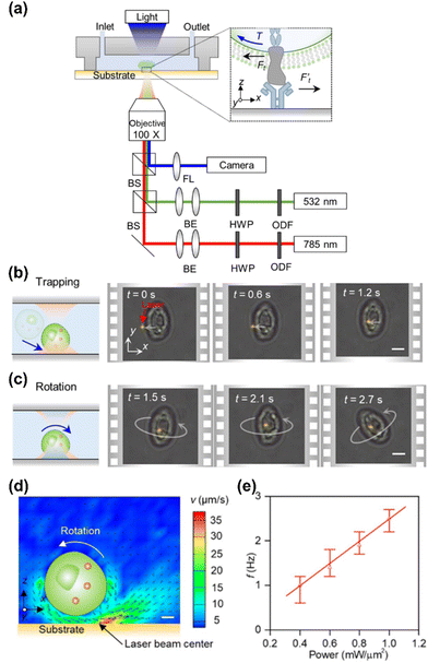 | ||
| Fig. 7 Opto-thermo-osmotic rotation techniques. (a) Experimental setup. HWP: half-wave plate. ODF: optical density filter. FL: focused lens. Inset: The receptors of the rotary cell interacting with the ligand molecules immobilized on the substrate. BS: beam splitter. BE: beam expander. (b) Schematics and time-resolved optical images showing the trapping of a yeast cell (S. cerevisiae) by a 785 nm beam. (c) Schematics and time-resolved optical images showing the stable rotation of the yeast cell with the secondary beam (532 nm). Scale bars: 5 μm. (d) Cross-sectional view of the simulated flow velocity in the vicinity of the cell. Scale bar: 1 μm. (e) The dependence of the rotational rate of the trapped cell on the optical power intensity of the 532 nm laser. The optical power intensity of the 785 nm beam is fixed at 1 mW μm−2. Adapted with permission.117 Copyright 2022, Springer Nature. | ||
3.3. Potential applications
Featuring simple optics, low power, and wide applicability to different objects, the optothermal rotation leads to a wide range of applications including single-cell mechanics, 3D bio-imaging, and micro/nanomotors.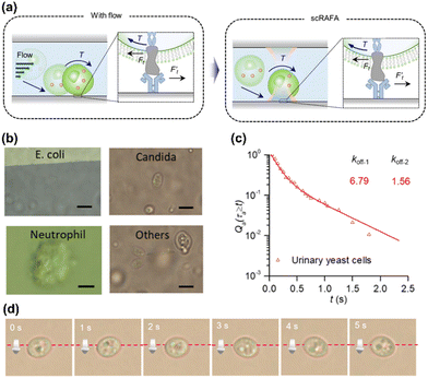 | ||
Fig. 8 Biological applications of optothermal rotation techniques. (a) Left: schematic illustration of the adhesion process of a cell. With a flow of biofluids (e.g., blood, urine), the cell will first attach to the endothelium cells as a substrate at an inclined angle. During the rolling, the receptors on the cell and the ligands on the substrate experience shear forces  . The curved arrow indicates the torque on the cell generated by the fluidic flow. Right: On the optothermal rotation platform, the cell suspended in liquid is first trapped on the functionalized substrate, mimicking the cell pre-attachment. Then, the measurement of the cell's shear adhesion kinetics can be obtained through the analysis of the light-driven out-of-plane rotation behavior of the cell. (b) Optical images of bacteria and cells trapped and rotated in clinical samples during the rolling adhesion measurement. Others: urinary organisms that we can hardly identify. Scale bars: 5 μm. (c) Qa (τa ≥ t), the fraction of chitin's transient adhesion with lifetime τa ≥ t, versus t for urinary yeast cells. The dissociate constants of the adhesion event (koff−1 = 6.79 s−1 and koff−1 = 1.56 s−1) were extracted by fitting the experimental data with double exponential decay curves. (d) Time-resolved optical images of a rolling yeast cell. (a–c) Adapted with permission.117 Copyright 2022, Springer Nature. (d) Adapted with permission.139 Copyright 2020, Institute of Electrical and Electronics Engineers. . The curved arrow indicates the torque on the cell generated by the fluidic flow. Right: On the optothermal rotation platform, the cell suspended in liquid is first trapped on the functionalized substrate, mimicking the cell pre-attachment. Then, the measurement of the cell's shear adhesion kinetics can be obtained through the analysis of the light-driven out-of-plane rotation behavior of the cell. (b) Optical images of bacteria and cells trapped and rotated in clinical samples during the rolling adhesion measurement. Others: urinary organisms that we can hardly identify. Scale bars: 5 μm. (c) Qa (τa ≥ t), the fraction of chitin's transient adhesion with lifetime τa ≥ t, versus t for urinary yeast cells. The dissociate constants of the adhesion event (koff−1 = 6.79 s−1 and koff−1 = 1.56 s−1) were extracted by fitting the experimental data with double exponential decay curves. (d) Time-resolved optical images of a rolling yeast cell. (a–c) Adapted with permission.117 Copyright 2022, Springer Nature. (d) Adapted with permission.139 Copyright 2020, Institute of Electrical and Electronics Engineers. | ||
4. Summary and outlook
As shown in Table 1, diverse optothermal rotation techniques are developed based on different working mechanisms, which can be implemented on different substrates (thermally responsive or not), in different media (e.g., surfactant solutions, biological media, or solid polymers), and to different target objects (e.g., colloidal particles or living cells). They can either have in-plane or out-of-plane rotation frequency ranging from Hz to kHz, which leads to various applications. We conclude this Feature Article by proposing a general guideline for selecting suitable optothermal rotation techniques in terms of different target objects, followed by a discussion about the existing challenges, and future opportunities in this field.| Techniques | Working principles | Rotation modes | Targets | Pros and cons | Ref. | ||
|---|---|---|---|---|---|---|---|
| Opto-thermophoretic rotation | Thermophoresis | In-plane | Microparticles, biological cells | √ Work in diverse liquids | 49 and 96 | ||
| × Need customized solutions for specific targets | |||||||
| Opto-thermoelectric rotation | Thermoelectricity | In-plane | Micro/nanoparticles | √ Work for most tiny particles | 98 | ||
| × Have limited biocompatibility | |||||||
| Opto-thermocapillary rotation | Thermo-capillarity | In-plane | Micro/nanoparticles | √ Work in solid-state | 107 | ||
| × Have limited biocompatibility | |||||||
| Opto-thermo-electrokinetic rotation | Thermo-electrokinetics | Out-of-plane | Micro/nanoparticles, biological cells | √ Work for most tiny particles and biological cells | 44 and 72 | ||
| × Need substrates with high surface charges | |||||||
| Opto-thermo-osmotic rotation | Thermo-osmosis | Out-of-plane/In-plane | Biological cells, microparticles | √ Allow single-cell characterizations in native liquids | 75, 117 and 125 | ||
| × Need proper coordination between two laser beams | |||||||
| Opto-thermo-convective rotation | Thermal convection | Out-of-plane | Microparticles, biological cells | √ Work for most particles in microscale and sub-millimetre-scale | 119 and 120 | ||
| × Is difficult for nanoscale rotation | |||||||
4.1. General guidelines
For the optimum performance, we provide general guidelines for the choices of proper optothermal rotation techniques for different target objects, including nanoparticles, microparticles, and biological cells.4.2. Challenges and opportunities
The main challenges of the current optothermal rotation techniques are the potential thermal damage and limited rotation rates. Though the optothermal rotation can minimize phototoxicity due to the low optical power, thermal stress from optical heating could lead to the photothermal degradation of delicate objects.146 In particular for optothermal convective and opto-thermo-capillary rotation techniques, higher optical powers are typically required compared to the other optothermal rotation techniques. In addition, it could be challenging to obtain an ultrahigh rotation rate (e.g., GHz) on an optothermal rotation platform. Intuitively, a larger rotation rate can be obtained from the higher optothermal torques powered by the higher optical power. However, the increasing temperature might reach the boiling point of the solution, where vapor bubbles can form and introduce strong Marangoni convection to suppress the optothermal torques. One possible solution to these two issues is to add a chip-size heat sink to lower the environmental temperature.147 Within a lower environmental temperature, the target temperature difference for the generation of optothermal torques can be obtained with a lower peak temperature, which can reduce the thermal damage and avoid the formation of vapor bubbles.40,96Optothermal rotation of objects down to a few nanometers or even atomic scale can be attractive to the study of virology and particle physics. Multiple optothermal effects have proven to be able to direct the migration of the particles with these small sizes.37 To implement the rotation of these extremely tiny objects, one promising strategy is to use the femtosecond laser in optothermal rotation techniques. Specifically, a femtosecond laser pulse can generate a highly localized and steeper temperature field. Under a higher temperature gradient, a more robust trap well and a larger optothermal torque can be produced, which is promising to achieve stable rotary control of nano-/atomic-scale items. Besides, due to the high energy density of a femtosecond laser beam, it can directly heat the liquid through nonlinear interactions to establish temperature fields. Thus, all existing optothermal rotation techniques can work without the requirement of light-absorbing substrates or objects, which further broadens the applicability of optothermal rotations.
We believe that, once the above-mentioned bottlenecks are overcome, more applications can be implemented by optothermal rotation. For instance, with the capability to noninvasively rotate smaller objects such as viruses, optothermal rotation can be used in single-virus mechanics. Specifically, the rolling adhesion of SARS-CoV-2 (∼0.1 μm) can be measured to help better understand the viral infection process. Another promising application is cell classification. Distinguishing different types of cells of high similarity is extremely challenging for existing optical imaging techniques. Optothermal rotation of cells integrated into standard optical microscopy will provide a collection of multiangle images at a high efficiency and, in combination with machine-learning-enhanced image analysis, could effectively reduce the quantity of the training samples and improve the classification accuracy.
Author contributions
H. D. and Y. Z. conceived the idea, designed the frame, and wrote the manuscript. Z. C. and C. P. assisted with the manuscript revision. Y. Z. supervised the project.Conflicts of interest
The authors declare no competing interests.Acknowledgements
H. D., Z. C., and Y. Z. acknowledge the financial support of the National Institute of General Medical Sciences of the National Institutes of Health (R01GM146962) and the National Science Foundation (NSF-ECCS-2001650). C. P. additionally acknowledges the financial support of UT Austin Undergraduate Research Fellowship.Notes and references
- D. G. Grier, Nature, 2003, 424, 810–816 CrossRef CAS PubMed.
- A. Ashkin, Nature, 1987, 330, 608–609 CrossRef.
- P. H. Jones, O. M. Maragò and G. Volpe, Optical Tweezers: Principles and Applications, Cambridge University Press, Cambridge, 2015 Search PubMed.
- C. J. Bustamante, Y. R. Chemla, S. Liu and M. D. Wang, Nat. Rev. Methods Primers, 2021, 1, 25 CrossRef CAS PubMed.
- L.-M. Zhou, Y. Shi, X. Zhu, G. Hu, G. Cao, J. Hu and C.-W. Qiu, ACS Nano, 2022, 16, 13264–13278 CrossRef CAS PubMed.
- A. Ashkin, J. M. Dziedzic, J. E. Bjorkholm and S. Chu, Opt. Lett., 1986, 11, 288–290 CrossRef CAS PubMed.
- A. Ashkin, J. M. Dziedzic and T. Yamane, Nature, 1987, 330, 769–771 CrossRef CAS PubMed.
- S. Sudhakar, M. K. Abdosamadi, T. J. Jachowski, M. Bugiel, A. Jannasch and E. Schäffer, Science, 2021, 371, eabd9944 CrossRef CAS PubMed.
- L. Shao and M. Käll, Adv. Funct. Mater., 2018, 28, 1706272 CrossRef.
- M. E. J. Friese, T. A. Nieminen, N. R. Heckenberg and H. Rubinsztein-Dunlop, Nature, 1998, 394, 348–350 CrossRef CAS.
- M. Liu, T. Zentgraf, Y. Liu, G. Bartal and X. Zhang, Nat. Nanotechnol., 2010, 5, 570–573 CrossRef CAS PubMed.
- J. Ahn, Z. Xu, J. Bang, P. Ju, X. Gao and T. Li, Nat. Nanotechnol., 2020, 15, 89–93 CrossRef CAS PubMed.
- A. Manjavacas, F. J. Rodríguez-Fortuño, F. J. García de Abajo and A. V. Zayats, Phys. Rev. Lett., 2017, 118, 133605 CrossRef PubMed.
- B. Strekha, S. Molesky, P. Chao, M. Krüger and A. W. Rodriguez, Phys. Rev. A, 2022, 106, 042222 CrossRef CAS.
- B. J. Nelson, I. K. Kaliakatsos and J. J. Abbott, Annu. Rev. Biomed. Eng., 2010, 12, 55–85 CrossRef CAS PubMed.
- Y. Alapan, U. Bozuyuk, P. Erkoc, A. C. Karacakol and M. Sitti, Sci. Rob., 2020, 5, eaba5726 CrossRef PubMed.
- Y. Li, X. Liu, X. Xu, H. Xin, Y. Zhang and B. Li, Adv. Funct. Mater., 2019, 29, 1905568 CrossRef CAS.
- U. G. Butaite, G. M. Gibson, Y. D. Ho, M. Taverne, J. M. Taylor and D. B. Phillips, Nat. Commun., 2019, 10, 1215 CrossRef PubMed.
- M. Kreysing, D. Ott, M. J. Schmidberger, O. Otto, M. Schurmann, E. Martin-Badosa, G. Whyte and J. Guck, Nat. Commun., 2014, 5, 5481 CrossRef CAS PubMed.
- F. Nan, X. Li, S. Zhang, J. Ng and Z. Yan, Sci. Adv., 2022, 8, eadd6664 CrossRef CAS PubMed.
- L. Tong, V. D. Miljkovic and M. Kall, Nano Lett., 2010, 10, 268–273 CrossRef CAS PubMed.
- F. Han, J. A. Parker, Y. Yifat, C. Peterson, S. K. Gray, N. F. Scherer and Z. Yan, Nat. Commun., 2018, 9, 4897 CrossRef PubMed.
- L. Paterson, M. P. MacDonald, J. Arlt, W. Sibbett, P. E. Bryant and K. Dholakia, Science, 2001, 292, 912–914 CrossRef CAS PubMed.
- J. E. Curtis and D. G. Grier, Phys. Rev. Lett., 2003, 90, 133901 CrossRef PubMed.
- E. Higurashi, H. Ukita, H. Tanaka and O. Ohguchi, Appl. Phys. Lett., 1994, 64, 2209–2210 CrossRef CAS.
- G. Vizsnyiczai, A. Buzas, B. Lakshmanrao Aekbote, T. Fekete, I. Grexa, P. Ormos and L. Kelemen, Biomed. Opt. Express, 2020, 11, 945–962 CrossRef CAS PubMed.
- T. Asavei, T. A. Nieminen, V. L. Y. Loke, A. B. Stilgoe, R. Bowman, D. Preece, M. J. Padgett, N. R. Heckenberg and H. Rubinsztein-Dunlop, New J. Phys., 2013, 15, 063016 CrossRef CAS.
- J. Ahn, Z. Xu, J. Bang, Y. H. Deng, T. M. Hoang, Q. Han, R. M. Ma and T. Li, Phys. Rev. Lett., 2018, 121, 033603 CrossRef CAS PubMed.
- A. Wittmeier, A. Leeth Holterhoff, J. Johnson and J. G. Gibbs, Langmuir, 2015, 31, 10402–10410 CrossRef CAS PubMed.
- F. van der Laan, R. Reimann, A. Militaru, F. Tebbenjohanns, D. Windey, M. Frimmer and L. Novotny, Phys. Rev. A, 2020, 102, 013505 CrossRef CAS.
- A. Würger, Rep. Prog. Phys., 2010, 73, 126601 CrossRef.
- S. A. Putnam, D. G. Cahill and G. C. Wong, Langmuir, 2007, 23, 9221–9228 CrossRef CAS PubMed.
- M. Braibanti, D. Vigolo and R. Piazza, Phys. Rev. Lett., 2008, 100, 108303 CrossRef PubMed.
- A. Wurger, Phys. Rev. Lett., 2008, 101, 108302 CrossRef PubMed.
- M. Reichl, M. Herzog, A. Gotz and D. Braun, Phys. Rev. Lett., 2014, 112, 198101 CrossRef PubMed.
- A. P. Bregulla, A. Wurger, K. Gunther, M. Mertig and F. Cichos, Phys. Rev. Lett., 2016, 116, 188303 CrossRef PubMed.
- Z. Chen, J. Li and Y. Zheng, Chem. Rev., 2022, 122, 3122–3179 CrossRef CAS PubMed.
- Z. Chen, P. S. Kollipara, H. Ding, A. Pughazhendi and Y. Zheng, Langmuir, 2021, 37, 1315–1336 CrossRef CAS PubMed.
- L. Lin, E. H. Hill, X. Peng and Y. Zheng, Acc. Chem. Res., 2018, 51, 1465–1474 CrossRef CAS PubMed.
- L. Lin, M. Wang, X. Peng, E. N. Lissek, Z. Mao, L. Scarabelli, E. Adkins, S. Coskun, H. E. Unalan, B. A. Korgel, L. M. Liz-Marzan, E. L. Florin and Y. Zheng, Nat. Photonics, 2018, 12, 195–201 CrossRef CAS PubMed.
- L. Lin, X. Peng, Z. Mao, X. Wei, C. Xie and Y. Zheng, Lab Chip, 2017, 17, 3061–3070 RSC.
- L. Lin, X. Peng, M. Wang, L. Scarabelli, Z. Mao, L. M. Liz-Marzan, M. F. Becker and Y. Zheng, ACS Nano, 2016, 10, 9659–9668 CrossRef CAS PubMed.
- H. R. Jiang, H. Wada, N. Yoshinaga and M. Sano, Phys. Rev. Lett., 2009, 102, 208301 CrossRef PubMed.
- H. Ding, Z. Chen, P. S. Kollipara, Y. Liu, Y. Kim, S. Huang and Y. Zheng, ACS Nano, 2022, 16, 10878–10889 CrossRef CAS PubMed.
- J. C. Ndukaife, A. V. Kildishev, A. G. Nnanna, V. M. Shalaev, S. T. Wereley and A. Boltasseva, Nat. Nanotechnol., 2016, 11, 53–59 CrossRef CAS PubMed.
- H. Ding, P. S. Kollipara, L. Lin and Y. Zheng, Nano Res., 2021, 14, 295–303 CrossRef PubMed.
- L. Lin, P. S. Kollipara, A. Kotnala, T. Jiang, Y. Liu, X. Peng, B. A. Korgel and Y. Zheng, Light: Sci. Appl., 2020, 9, 34 CrossRef CAS PubMed.
- E. H. Hill, J. Li, L. Lin, Y. Liu and Y. Zheng, Langmuir, 2018, 34, 13252–13262 CrossRef CAS PubMed.
- X. Peng, L. Lin, E. H. Hill, P. Kunal, S. M. Humphrey and Y. Zheng, J. Phys. Chem. C, 2018, 122, 24226–24234 CrossRef CAS.
- Y. Liu, L. Lin, B. Bangalore Rajeeva, J. W. Jarrett, X. Li, X. Peng, P. Kollipara, K. Yao, D. Akinwande, A. K. Dunn and Y. Zheng, ACS Nano, 2018, 12, 10383–10392 CrossRef CAS PubMed.
- J. Li, Z. Chen, Y. Liu, P. S. Kollipara, Y. Feng, Z. Zhang and Y. Zheng, Sci. Adv., 2021, 7, eabh1101 CrossRef CAS.
- H. Ding, P. S. Kollipara, A. Kotnala, Z. Chen and Y. Zheng, Proc. SPIE, 2021, 11798, 117981U Search PubMed.
- L. Lin, X. Peng, Z. Mao, W. Li, M. N. Yogeesh, B. B. Rajeeva, E. P. Perillo, A. K. Dunn, D. Akinwande and Y. Zheng, Nano Lett., 2016, 16, 701–708 CrossRef CAS PubMed.
- B. B. Rajeeva, M. A. Alabandi, L. Lin, E. P. Perillo, A. K. Dunn and Y. Zheng, J. Mater. Chem. C, 2017, 5, 5693–5699 RSC.
- L. Lin, S. Lepeshov, A. Krasnok, T. Jiang, X. Peng, B. A. Korgel, A. Alu and Y. Zheng, Mater. Today, 2019, 25, 10–20 CrossRef CAS PubMed.
- C. Zhao, P. J. Shah and L. J. Bissell, Nanoscale, 2019, 11, 16187–16199 RSC.
- M. S. Alam, Q. Zhan and C. Zhao, Nano Lett., 2020, 20, 5057–5064 CrossRef CAS PubMed.
- L. Lin, X. Peng and Y. Zheng, Chem. Commun., 2017, 53, 7357–7360 RSC.
- Y. Kim, H. Ding and Y. Zheng, Nano Lett., 2020, 20, 7020–7027 CrossRef CAS PubMed.
- A. Kotnala, P. S. Kollipara, J. Li and Y. Zheng, Nano Lett., 2020, 20, 768–779 CrossRef CAS PubMed.
- A. Kotnala, H. Ding and Y. Zheng, ACS Photonics, 2021, 8, 1673–1682 CrossRef CAS PubMed.
- M. Xuan, J. Shao, C. Gao, W. Wang, L. Dai and Q. He, Angew. Chem., Int. Ed., 2018, 57, 12463–12467 CrossRef CAS PubMed.
- S. Ghosh and A. Ghosh, Sci. Rob., 2018, 3, eaaq0076 CrossRef PubMed.
- R. Piazza and A. Guarino, Phys. Rev. Lett., 2002, 88, 208302 CrossRef PubMed.
- S. Wiegand, J. Phys.: Condens. Matter, 2004, 16, R357–R379 CrossRef CAS.
- W. Köhler and K. I. Morozov, J. Non-Equilib. Thermodyn., 2016, 41, 151–197 Search PubMed.
- Z. Kang, J. Chen, S. Y. Wu, K. Chen, S. K. Kong, K. T. Yong and H. P. Ho, Sci. Rep., 2015, 5, 9978 CrossRef CAS PubMed.
- N. Takeyama and K. Nakashima, J. Solution Chem., 1988, 17, 305–325 CrossRef CAS.
- F. Bresme, A. Lervik, D. Bedeaux and S. Kjelstrup, Phys. Rev. Lett., 2008, 101, 020602 CrossRef PubMed.
- Y. Zhao, H. S. Lai, G. Zhang, G. B. Lee and W. J. Li, Lab Chip, 2014, 14, 4426–4434 RSC.
- W. Liang, X. Yang, J. Wang, Y. Wang, H. Zhang, W. Yang and L. Liu, Opt. Lett., 2020, 45, 2454–2457 CrossRef CAS PubMed.
- H. Ding, P. S. Kollipara, Y. Kim, A. Kotnala, J. Li, Z. Chen and Y. Zheng, Sci. Adv., 2022, 8, eabn8498 CrossRef CAS PubMed.
- P. Atkins and J. de Paula, Physical Chemistry, Oxford University Press, 8th edn, 2006 Search PubMed.
- M. J. Blandamer, J. Burgess, P. P. Duce, R. E. Robertson and J. W. M. Scott, J. Chem. Soc., Faraday Trans. 1, 1981, 77, 2281–2286 RSC.
- X. Lou, N. Yu, R. Liu, K. Chen and M. Yang, Soft Matter, 2018, 14, 1319–1326 RSC.
- M. Franzl and F. Cichos, Nat. Commun., 2022, 13, 656 CrossRef PubMed.
- T. L. Bergman, T. L. Bergman, F. P. Incropera, D. P. Dewitt and A. S. Lavine, Fundamentals of heat and mass transfer, John Wiley & Sons, 2011 Search PubMed.
- D. Ma, H. Ding, H. Meng, L. Feng, Y. Wu, J. Shiomi and N. Yang, Phys. Rev. B, 2016, 94, 165434 CrossRef.
- H. Ding, G. Peng, S. Mo, D. Ma, S. W. Sharshir and N. Yang, Nanoscale, 2017, 9, 19066–19072 RSC.
- B. J. Roxworthy, A. M. Bhuiya, S. P. Vanka and K. C. Toussaint, Jr., Nat. Commun., 2014, 5, 3173 CrossRef PubMed.
- J. S. Donner, G. Baffou, D. McCloskey and R. Quidant, ACS Nano, 2011, 5, 5457–5462 CrossRef CAS PubMed.
- A. Girot, N. Danne, A. Wurger, T. Bickel, F. Ren, J. C. Loudet and B. Pouligny, Langmuir, 2016, 32, 2687–2697 CrossRef CAS PubMed.
- L. Lin, P. S. Kollipara and Y. Zheng, Mater. Today, 2019, 28, 49–62 CrossRef PubMed.
- Y. Liu, Z. Wu, P. S. Kollipara, R. Montellano, K. Sharma and Y. Zheng, ACS Nano, 2021, 15, 6448–6456 CrossRef CAS PubMed.
- G. Peng, H. Ding, S. W. Sharshir, X. Li, H. Liu, D. Ma, L. Wu, J. Zang, H. Liu, W. Yu, H. Xie and N. Yang, Appl. Therm. Eng., 2018, 143, 1079–1084 CrossRef CAS.
- E. Lee, D. Huang and T. Luo, Nat. Commun., 2020, 11, 2404 CrossRef CAS PubMed.
- E. Lee and T. Luo, Sci. Adv., 2020, 6, eaaz3646 CrossRef CAS PubMed.
- Y. I. Yalamov, V. B. Kutukov and E. R. Shchukin, J. Colloid Interface Sci., 1976, 57, 564–571 CrossRef CAS.
- O. Jovanovic, J. Quant. Spectrosc. Radiat. Transfer, 2009, 110, 889–901 CrossRef CAS.
- Z. Gong, Y.-L. Pan, G. Videen and C. Wang, J. Quant. Spectrosc. Radiat. Transfer, 2018, 214, 94–119 CrossRef CAS.
- S. Liu, L. Lin and H. B. Sun, ACS Nano, 2021, 15, 5925–5943 CrossRef CAS PubMed.
- S. Duhr and D. Braun, Proc. Natl. Acad. Sci. U. S. A., 2006, 103, 19678–19682 CrossRef CAS PubMed.
- F. M. Weinert and D. Braun, Phys. Rev. Lett., 2008, 101, 168301 CrossRef PubMed.
- M. Braun and F. Cichos, ACS Nano, 2013, 7, 11200–11208 CrossRef CAS PubMed.
- M. Braun, A. P. Bregulla, K. Gunther, M. Mertig and F. Cichos, Nano Lett., 2015, 15, 5499–5505 CrossRef CAS PubMed.
- L. Lin, X. Peng, X. Wei, Z. Mao, C. Xie and Y. Zheng, ACS Nano, 2017, 11, 3147–3154 CrossRef CAS PubMed.
- J. L. Anderson, Annu. Rev. Fluid Mech., 1989, 21, 61–99 CrossRef.
- X. Peng, Z. Chen, P. S. Kollipara, Y. Liu, J. Fang, L. Lin and Y. Zheng, Light: Sci. Appl., 2020, 9, 141 CrossRef PubMed.
- D. Vigolo, S. Buzzaccaro and R. Piazza, Langmuir, 2010, 26, 7792–7801 CrossRef CAS PubMed.
- L. Lin, J. Zhang, X. Peng, Z. Wu, A. C. H. Coughlan, Z. Mao, M. A. Bevan and Y. Zheng, Sci. Adv., 2017, 3, e1700458 CrossRef PubMed.
- P. S. Kollipara, L. Lin and Y. Zheng, J. Phys. Chem. C, 2019, 123, 21639–21644 CrossRef CAS PubMed.
- S. Nakata, Y. Iguchi, S. Ose, M. Kuboyama, T. Ishii and K. Yoshikawa, Langmuir, 1997, 13, 4454–4458 CrossRef CAS.
- J. Deng, M. Molaei, N. G. Chisholm, T. Yao, A. Read and K. J. Stebe, Curr. Opin. Colloid Interface Sci., 2022, 61, 101629 CrossRef CAS.
- A. Würger, J. Fluid Mech., 2014, 752, 589–601 CrossRef.
- H. Kim, S. Sundaram, J. H. Kang, N. Tanjeem, T. Emrick and R. C. Hayward, Proc. Natl. Acad. Sci. U. S. A., 2021, 118, e2024581118 CrossRef CAS PubMed.
- S. Nagelberg, J. F. Totz, M. Mittasch, V. Sresht, L. Zeininger, T. M. Swager, M. Kreysing and M. Kolle, Phys. Rev. Lett., 2021, 127, 144503 CrossRef CAS PubMed.
- J. Li, P. S. Kollipara, Y. Liu, K. Yao, Y. Liu and Y. Zheng, ACS Nano, 2022, 16, 8820–8826 CrossRef CAS PubMed.
- J. Li, Y. Liu, L. Lin, M. Wang, T. Jiang, J. Guo, H. Ding, P. S. Kollipara, Y. Inoue, D. Fan, B. A. Korgel and Y. Zheng, Nat. Commun., 2019, 10, 5672 CrossRef CAS PubMed.
- A. B. Yasunaga and I. T. S. Li, Sci. Adv., 2021, 7, eabe6984 CrossRef CAS PubMed.
- I. T. S. Li, T. Ha and Y. R. Chemla, Sci. Rep., 2017, 7, 44502 CrossRef CAS PubMed.
- X. Ding, S. C. Lin, B. Kiraly, H. Yue, S. Li, I. K. Chiang, J. Shi, S. J. Benkovic and T. J. Huang, Proc. Natl. Acad. Sci. U. S. A., 2012, 109, 11105–11109 CrossRef CAS PubMed.
- D. Ahmed, A. Ozcelik, N. Bojanala, N. Nama, A. Upadhyay, Y. Chen, W. Hanna-Rose and T. J. Huang, Nat. Commun., 2016, 7, 11085 CrossRef CAS PubMed.
- S. Jeon, S. Kim, S. Ha, S. Lee, E. Kim, S. Y. Kim, S. H. Park, J. H. Jeon, S. W. Kim, C. Moon, B. J. Nelson, J.-Y. Kim, S.-W. Yu and H. Choi, Sci. Rob., 2019, 4, eaav4317 CrossRef PubMed.
- D. Ahmed, T. Baasch, N. Blondel, N. Laubli, J. Dual and B. J. Nelson, Nat. Commun., 2017, 8, 770 CrossRef PubMed.
- T. Tang, Y. Hosokawa, T. Hayakawa, Y. Tanaka, W. Li, M. Li and Y. Yalikun, Engineering, 2022, 10, 110–126 CrossRef.
- L. Huang, P. Zhao, F. Liang and W. Wang, Methods Cell Biol., 2018, 148, 97–116 Search PubMed.
- Y. Liu, H. Ding, J. Li, X. Lou, M. Yang and Y. Zheng, eLight, 2022, 2, 13 CrossRef PubMed.
- M. Heidari, A. Bregulla, S. Muinos Landin, F. Cichos and R. von Klitzing, Langmuir, 2020, 7775–7780, DOI:10.1021/acs.langmuir.0c00461.
- L. Dai, Z. Ge, N. Jiao and L. Liu, Small, 2019, e1902815, DOI:10.1002/smll.201902815.
- S. Kumar, M. Gunaseelan, R. Vaippully, A. Kumar, M. Ajith, G. Vaidya, S. Dutta and B. Roy, Biomed. Opt. Express, 2020, 11, 3555 CrossRef CAS PubMed.
- M. Xie, J. K. Mills, Y. Wang, M. Mahmoodi and D. Sun, IEEE Trans. Autom. Sci. Eng., 2016, 13, 543–551 Search PubMed.
- M. Xie, A. Shakoor, C. Li and D. Sun, Int. J. Robust Nonlinear Control, 2019, 29, 4859–4871 CrossRef.
- M. Xie, A. Shakoor, Y. Shen, J. K. Mills and D. Sun, IEEE Trans. Biomed. Eng., 2019, 66, 199–207 Search PubMed.
- Y. T. Maeda, T. Tlusty and A. Libchaber, Proc. Natl. Acad. Sci. U. S. A., 2012, 109, 17972–17977 CrossRef CAS PubMed.
- W. Bai, M. Shao, J. Zhou, Q. Zhao, F. Ji and M. C. Zhong, Rev. Sci. Instrum., 2022, 93, 084902 CrossRef CAS PubMed.
- N. V. Churaev, B. V. Derjaguin and V. M. Muller, Surface forces, Springer Science & Business Media, 2013 Search PubMed.
- D. Braun and A. Libchaber, Phys. Rev. Lett., 2002, 89, 188103 CrossRef PubMed.
- S. Duhr, S. Arduini and D. Braun, Eur. Phys. J. E: Soft Matter Biol. Phys., 2004, 15, 277–286 CrossRef CAS PubMed.
- V. Brasiliense, P. Berto, P. Aubertin, E. Maisonhaute, C. Combellas, G. Tessier, A. Courty and F. Kanoufi, ACS Nano, 2018, 12, 10833–10842 CrossRef CAS PubMed.
- H. Cong, F. C. Loo, J. Chen, Y. Wang, S. K. Kong and H. P. Ho, Biosens. Bioelectron., 2019, 133, 236–242 CrossRef CAS PubMed.
- L. Dai, D. Lin, X. Wang, N. Jiao and L. Liu, ACS Appl. Mater. Interfaces, 2020, 12, 57587–57597 CrossRef CAS PubMed.
- C. R. Monks, B. A. Freiberg, H. Kupfer, N. Sciaky and A. Kupfer, Nature, 1998, 395, 82–86 CrossRef CAS PubMed.
- C. Zhu, G. Bao and N. Wang, Annu. Rev. Biomed. Eng., 2000, 2, 189–226 CrossRef CAS PubMed.
- Z. Zhang and D. Ahmed, Light: Sci. Appl., 2022, 11, 266 CrossRef CAS PubMed.
- D. Wrapp, N. Wang, K. S. Corbett, J. A. Goldsmith, C. L. Hsieh, O. Abiona, B. S. Graham and J. S. McLellan, Science, 2020, 367, 1260–1263 CrossRef CAS PubMed.
- J. Yang, S. J. L. Petitjean, M. Koehler, Q. Zhang, A. C. Dumitru, W. Chen, S. Derclaye, S. P. Vincent, P. Soumillion and D. Alsteens, Nat. Commun., 2020, 11, 4541 CrossRef CAS PubMed.
- J. Swoger, P. Verveer, K. Greger, J. Huisken and E. H. Stelzer, Opt. Express, 2007, 15, 8029–8042 CrossRef PubMed.
- T. Kolb, S. Albert, M. Haug and G. Whyte, J. Biophotonics, 2015, 8, 239–246 CrossRef CAS PubMed.
- H. Ding, Z. Chen and Y. Zheng, 2020 Conference on Lasers and Electro-Optics (CLEO), 2020, pp. 1–2.
- L. Xu, F. Mou, H. Gong, M. Luo and J. Guan, Chem. Soc. Rev., 2017, 46, 6905–6926 RSC.
- Z. Liang and D. Fan, Sci. Adv., 2018, 4, eaau0981 CrossRef PubMed.
- D. Fan, Z. Yin, R. Cheong, F. Q. Zhu, R. C. Cammarata, C. L. Chien and A. Levchenko, Nat. Nanotechnol., 2010, 5, 545–551 CrossRef CAS PubMed.
- H. Zhou, C. C. Mayorga-Martinez, S. Pane, L. Zhang and M. Pumera, Chem. Rev., 2021, 121, 4999–5041 CrossRef CAS PubMed.
- Q. You, Y. Wang, Z. Zhang, H. Zhang, T. Tsuchiya and O. Tabata, Appl. Opt., 2020, 59, 1627–1632 CrossRef PubMed.
- M. Han, B. Kim, H. Lim, H. Jang and E. Kim, Adv. Mater., 2020, 32, e1905096 CrossRef PubMed.
- A. Blazquez-Castro, Micromachines, 2019, 10, 507 CrossRef PubMed.
- X. Hao, B. Peng, G. Xie and Y. Chen, Appl. Therm. Eng., 2016, 100, 170–178 CrossRef.
| This journal is © The Royal Society of Chemistry 2023 |

