 Open Access Article
Dome-shaped mode lasing from liquid crystals for full-color lasers and high-sensitivity detection†
Rui
Duan‡
a,
Zitong
Zhang‡
a,
Lian
Xiao
a,
Tianhua
Ren
a,
Xuehong
Zhou
 a,
Yi Tian
Thung
a,
Van Duong
Ta
a,
Yi Tian
Thung
a,
Van Duong
Ta
 *b,
Jun
Yang
*c and
Handong
Sun
 *a
*a
aDivision of Physics and Applied Physics, School of Physical and Mathematical Sciences, Nanyang Technological University, 637371, Singapore. E-mail: HDSun@ntu.edu.sg
bDepartment of Optical Devices, Le Quy Don Technical University, Hanoi 100000, Vietnam. E-mail: duong.ta@lqdtu.edu.vn
cGuangdong Provincial Key Laboratory of Information Photonics Technology, College of Information Engineering, Guangdong University of Technology, Guangzhou 510006, China. E-mail: yangj@gdut.edu.cn
First published on 13th January 2023
Abstract
In this communication, we report a new class of oscillation mode, dome-shaped mode (DSM), in liquid crystal (LC) microlasers. A record high Q-factor over 24![[thin space (1/6-em)]](https://www.rsc.org/images/entities/char_2009.gif) 000 is achieved in LC soft-matter microlasers. We successfully presented a proof-of-concept demonstration of red, green, blue (RGB) LC-DSM microlaser pixels with a 74% broader achievable color gamut than the standard RGB color space. Besides, the detection limit for acetone vapor molecules is as low as 0.5 ppm, confirming the excellent potential of the proposed LC-DSM microlaser in ultra-high sensitivity detection.
000 is achieved in LC soft-matter microlasers. We successfully presented a proof-of-concept demonstration of red, green, blue (RGB) LC-DSM microlaser pixels with a 74% broader achievable color gamut than the standard RGB color space. Besides, the detection limit for acetone vapor molecules is as low as 0.5 ppm, confirming the excellent potential of the proposed LC-DSM microlaser in ultra-high sensitivity detection.
Optical microresonators are one of the most important building blocks for soft-matter microlasers due to their unique ability to confine photons within ultra-small volumes.1–5 In the past two decades, resonators including whispering-gallery-mode (WGM) cavities,6–9 Fabry–Perot (F–P) cavities,10,11 and photonic crystal cavities12,13 have been explored. Although these various resonators have exerted their respective advantages in numerous cutting-edge applications, such as miniaturized lasers, laser displays, and sensing detection, there remains an imminent need to further optimize the quality (Q)-factors and lasing thresholds.
Recently, liquid crystals, a typical kind of soft-matter materials, saw breakthroughs in areas from laser-based biosensing and imaging, to photonic integrated circuits, inspired by their ultra-high interfacial sensitivity and excellent optoelectronic properties.14–19 However, the weak mechanical stability and high scattering loss of conventional laser cavities for soft-matter materials such as LCs and polymers have become innegligible issues. To date, the lasing Q-factor of most soft-matter microlasers is restricted to the order of 103, which poses one of the greatest hindrances to the further development of soft-matter photonics and their applications.1,15 Hence, there is an urgency to find a feasible solution to overcome the constraints of the development of soft-matter lasers.
Herein, for the first time, a new class of optical mode, dome-shaped mode (DSM), in the hemispherical nematic LC 4′-pentyl-4-biphenylcarbonitrile (5CB) resonators is achieved through the one-step inkjet-printing technique. Different from the conventional F–P mode and WGM, the combined contributions of the total internal reflection of the light along the cavity surface and the strong vertical reflection from the substrate form the DSMs with a unique dome-shaped oscillatory path. The proposed LC-DSM microlaser achieves a lasing Q-factor of over 24![[thin space (1/6-em)]](https://www.rsc.org/images/entities/char_2009.gif) 000, clinching a new record in soft-matter microlasers.
000, clinching a new record in soft-matter microlasers.
In this work, we have realized the size-controlled array preparation of DSM microlasers. A proof-of-concept demonstration of red, green, blue (RGB) DSM microlaser pixels with 74% broader achievable color gamut than the standard RGB color space is presented. In the aspects of sensing, the strong system response of acetone gas with a concentration as low as 0.5 ppm was observed, preliminarily confirming the excellent potential of the proposed LC-DSM microlaser in ultra-high sensitivity and quantitative sensing detection.
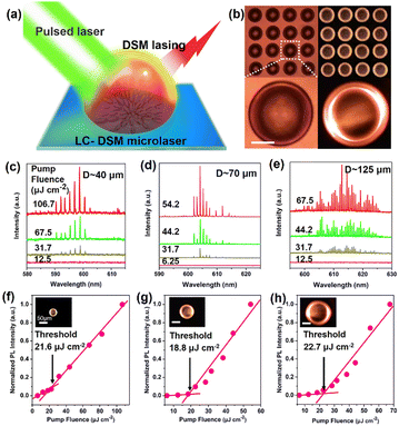
Ultrasonic vibration-assisted inkjet-printing was selected for the fabrication of size-controllable LC-DSM microlaser arrays (Fig. S1, ESI†). Fig. 1(a) illustrates the basic principle of the DSMs formed in the LC hemispherical microcavity on the distributed Bragg reflector (DBR) substrate. The combined contributions of total internal reflection of the light along the cavity surface and the strong vertical reflection from the highly reflective DBR substrate form the DSMs with a unique dome-shaped oscillatory path. From our studies, a larger contact angle (>80°) between the cavity and the substrate generally leads to DSM lasing with higher Q-factors owing to the better mode confinement (detailed discussion will be carried out later). The size of the individual LC-DSM microcavity can be readily controlled by using glass needles with different tip diameters (Fig. 1(b) and Fig. S2–S4, ESI†). Before commencing the inkjet-printing process, a thin hydrophobic layer was uniformly spread on the DBR surface. The introduction of the functional layer induces the hydrophobic effect, making the contact angle formed at the interface between the cavity and the substrate as high as 85° (see Experimental and simulation section and Fig. S6, ESI†).
Fig. 1(c)–(e) depicts the power-dependent PL spectra of individual DSM microlasers with different bottom diameters. Some circulating light with a specific frequency conforming to the resonant conditions is continuously amplified by total internal reflection on the surface of the cavity. Increasing the pump power to the critical value induces the sudden appearance of sharp and comb-like discrete peaks, indicating the evolution from spontaneous emission to lasing. As shown in Fig. 1(f)–(h), the knee-joint-like nonlinear increase in emission intensity with pump intensity further demonstrates the lasing phenomenon and defines the lasing threshold. Benefiting from the large refractive index contrast (Δn ∼ 0.70) between the LC cavity and the ambient medium as well as the uniquely smooth cavity surface, the light confinement of the DSMs cyclic oscillation in the resonator is effectively guaranteed. The lasing thresholds of the three series of LC microlasers are close, all around ∼20 μJ cm−2. Above the laser threshold, the dazzling bright spots on both sides of the spherical crown of LC droplets appear, which is significantly different from the bright ring of the WGMs (Fig. 1(f)–(h), inset). As shown in Table S1 (ESI†), the lasing threshold of the proposed DSM microlaser is at least one order of magnitude lower than that of other types of liquid and soft-matter microlasers.
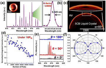
Despite tremendous efforts made to improve the lasing performance in soft-matter laser arrays, most works focus only on the advancement of precise patterning while the low Q-factor (mostly limited to the order of 103) as well as poor stability still thwarts the upgrading of soft-matter microlaser networks. Notably, as displayed in Fig. 2(a) and (b) and Table S1 (ESI†), the Q-factor of the proposed LC-DSM microlaser exceeds 24![[thin space (1/6-em)]](https://www.rsc.org/images/entities/char_2009.gif) 000, creating a record-high lasing Q-factor in the state-of-the-art liquid microlaser devices. The Q-factor of the LC-WGM microlaser with 35° contact angle is only ∼2200, which is one-tenth of that in the case of DSM lasing operation. Apart from the low Q-factor, the lasing threshold of the LC-WGM microlaser was determined to be ∼105.4 μJ cm−2, which is 5 times that of the DSM counterpart lasers (Fig. S8 and S9, ESI†). In fact, for the WGM cavity, the contact surface between the cavity wall and the substrate is not actually a strict circle, but irregular. Although WGMs can be excited, the irregular geometric profile of the cavity increases the energy loss substantially. But for DSMs, the surface tension makes the surface of the cavity in the air absolutely smooth, which makes the performance of the DSM laser much better than that of the WGM laser.
000, creating a record-high lasing Q-factor in the state-of-the-art liquid microlaser devices. The Q-factor of the LC-WGM microlaser with 35° contact angle is only ∼2200, which is one-tenth of that in the case of DSM lasing operation. Apart from the low Q-factor, the lasing threshold of the LC-WGM microlaser was determined to be ∼105.4 μJ cm−2, which is 5 times that of the DSM counterpart lasers (Fig. S8 and S9, ESI†). In fact, for the WGM cavity, the contact surface between the cavity wall and the substrate is not actually a strict circle, but irregular. Although WGMs can be excited, the irregular geometric profile of the cavity increases the energy loss substantially. But for DSMs, the surface tension makes the surface of the cavity in the air absolutely smooth, which makes the performance of the DSM laser much better than that of the WGM laser.
The DSM mechanism and the reason for the high Q-factor are further revealed by numerical simulations (see ESI† for details of the simulation parameters and methods). Fig. 2(c) displays the simulated electric field distribution in a typical LC-DSM cavity with a bottom diameter of 40 μm. As expected, the circulating light resonates strongly along the side surface of the cavity and the highly reflective DBR substrate to form the DSMs. The localized electric field magnification region indicates that almost all the light field is effectively confined inside the cavity, with a small portion penetrating through the interface as an evanescent field. Furthermore, the good agreement between the theoretical and experimental results of free spectral range also verifies the mechanism of DSMs (Fig. S10, ESI†). Notably, quantitative analysis of the normalized electric field intensity (Fig. S11, ESI†) reveals that only 1.46% of the energy of the light field penetrates into the air layer, which clearly elucidates the underlying mechanism of the LC-DSM laser with ultra-high lasing Q-factor. In summary, all comparison results demonstrate the unique advantages of DSM in our paradigm, both in terms of Q-factor and lasing threshold. Furthermore, Fig. S12 (ESI†) reveals the distribution of the cavity field when the contact angle is 80° and 75°. As the contact angle decreases, the DSMs are difficult to maintain, which proves the importance of large contact angle to energy constraints. In fact, when the angle is further reduced (∼70°), the laser intensity of the DSMs will be significantly stronger than the WGMs when both of them exist in cavities at the same time (Fig. S13, ESI†). Besides the lasing threshold and Q-factor, another key factor restricting the practicability of the soft matter microcavity is the poor lasing output stability. Fig. 2(d) demonstrates the evolution of the output intensity of our LC-DSM microlaser excited over 100![[thin space (1/6-em)]](https://www.rsc.org/images/entities/char_2009.gif) 000 times under continuous excitation with strong nanosecond pumping (∼10 Pth). The results revealed that up to ∼30% of the initial intensity of the laser output was retained after more than 100
000 times under continuous excitation with strong nanosecond pumping (∼10 Pth). The results revealed that up to ∼30% of the initial intensity of the laser output was retained after more than 100![[thin space (1/6-em)]](https://www.rsc.org/images/entities/char_2009.gif) 000 strong pumping cycles. Besides, all lasing peaks were most stabilized at their initial positions during the measurement.
000 strong pumping cycles. Besides, all lasing peaks were most stabilized at their initial positions during the measurement.
The polarization properties of microlasers play an extremely important role in flat-panel displays, vector beams, and optical modulation. The strong contrast between the lasing intensities corresponding to different rotation angles (θ) of the linear polarizer clearly shows a good polarization dependence of the LC-DSM microlaser emission (Fig. 2(e) and (f)). Furthermore, the optical images of the microlaser under different θ indicate that the LC-DSM belongs to the transverse electric mode, and the electric field oscillation direction is parallel to the cavity surface (Fig. S14, ESI†). The polarization factor R is determined to be 0.85, which is significantly higher than that of WGM microlasers.9,20
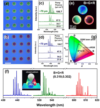
Lasers with a wide range of selectable wavelengths are highly pursued in lighting technologies and portable flat panel display industries owing to their wide color gamut, high saturation, and good contrast ratio. To conceptually demonstrate the feasibility of the LC-DSM microlaser arrays with an extremely wide tuning emission range, we utilized a similar technique to fabricate green- and blue-emitting arrays by integrating a mixture of the respective dyes and LC on DBR substrates with high reflectivity in the corresponding wavelength bands (Fig. 3(a) and (b)). With the increment of the pump fluence, the appearance of sharp lasing peaks in the emission spectra (Fig. 3(c) and (d)) manifests the occurrence of lasing actions in these green and blue LC-DSM microlasers. Notably, benefiting from the high refractive index of 5CB and inherently remarkable Q-factor of DSMs, the lasing thresholds of both green and blue arrays were as low as ∼27.4 μJ cm−2 and ∼33.4 μJ cm−2, respectively (Fig. S16, ESI†), which is essential for self-emissive high-quality laser sub-pixel sectors. Fig. 3(e) displays the photoluminescence image of a tri-chromatic pixel microunit composed of blue (B), green (G), and red (R) DSM microlasers. Afterward, these three primary sub-pixel lasers were pumped simultaneously to successfully generate a balanced white laser composed of tri-color lasing emissions (Fig. 3(f)), with their calculated chromaticity distributions presented in Fig. 3(g) and Table S2 (ESI†). The CIE1931 coordinates of the tri-color laser array presented in the chromaticity diagram, which are very close to those of CIE standard white illuminant D6541, clearly indicate the actualization of a full-color laser. Given the color gamut area in Fig. 3(g), our fabricated panchromatic LC-DSM microlasers could cover 74% more perceived colors than the standard RGB space. Such a wide color gamut fully demonstrates the advantages of LC-DSM microlaser arrays in realizing vivid display panels with high color saturation and provides valuable inspiration for the development of next-generation flat-panel laser displays.
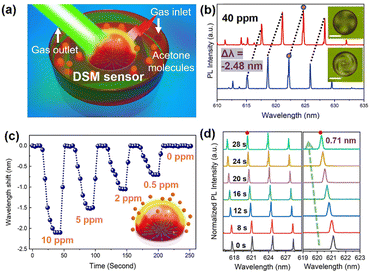
Besides the potential in full-color displays, biochemical molecular detection is another important ability of proposed LC-DSM microlasers. The real-time monitoring detection of acetone vapor molecules as target molecules was carried out (Fig. 4(a)). For conventional resonators, acetone molecules will only be strongly attached to the cavity surface, thus affecting the refractive index of the environmental medium.21,22 Interestingly, for our LC-DSM cavity, the attachment of acetone also affects the orientational behaviors of the LC molecules at the cavity surface, thereby further amplifying the disturbance caused by the target. As shown in Fig. 4(b), the polarized optical images of the LC-DSM microcavity changed significantly after the introduction of 40 ppm acetone vapor. A spectral blue shift of 2.48 nm was also observed, confirming the preliminary feasibility of the acetone molecular monitoring. To explore the detectability of the LC-DSM sensor to gas molecules, acetone vapor of different concentrations (from 0 ppm to 10 ppm) is circulated into the detection chamber. With the decrease of the acetone concentration, the initial response rate of the system gradually slows down, and the wavelength shift response also weakens accordingly (Fig. 4(c)). Surprisingly, the LC-DSM sensing system still has a strong spectral response of 710 pm in the 30s monitoring window for acetone vapor as low as 0.5 ppm (Fig. 4(d)). Due to the performance limitation of the gas generator, we did not continue to reduce the concentration of acetone vapor. Nevertheless, our practical detection result is at least 2 orders of magnitude better than that of the WGM-based sensors and most of the chemiresistive sensors.21,23 Therefore, the LC-DSM microlaser will provide a new ultra-high sensitive and quantitative method for detecting biochemical molecules.
In summary, we have developed functional full-color LC-DSM microlaser arrays and a high-sensitivity sensor for the first time with ultra-high Q-factor exceeding 24![[thin space (1/6-em)]](https://www.rsc.org/images/entities/char_2009.gif) 000 and lasing threshold down to ∼20 μJ cm−2. The three-primary RGB laser pixel unit was successfully demonstrated and finally achieved an ultra-wide color gamut 74% larger than the standard RGB space. Besides, the actual detection limit for acetone vapor is as low as 0.5 ppm, indicating that the DSM microlaser has excellent potential in the application of high-sensitivity detection. In addition, benefiting from the current advances in gain materials, we believe that DSM lasers have good potential to achieve wavelength tuning,1,24 upconversion emission,25 and CW pumped3,9,26 lasing emission in the future.
000 and lasing threshold down to ∼20 μJ cm−2. The three-primary RGB laser pixel unit was successfully demonstrated and finally achieved an ultra-wide color gamut 74% larger than the standard RGB space. Besides, the actual detection limit for acetone vapor is as low as 0.5 ppm, indicating that the DSM microlaser has excellent potential in the application of high-sensitivity detection. In addition, benefiting from the current advances in gain materials, we believe that DSM lasers have good potential to achieve wavelength tuning,1,24 upconversion emission,25 and CW pumped3,9,26 lasing emission in the future.
This work is supported by A*Star-AME-IRG-A20E5c0083, NRF-CRP23-2019-0007. V. D. T. acknowledges the support from the Vietnam National Foundation for Science and Technology Development (NAFOSTED) under grant number 103.03-2021.62. J. Y. also acknowledges the support from the National Science Fund for Distinguished Young Scholars of China (61925501), the Guangdong Introducing Innovative and Entrepreneurial Teams (2019ZT08X340) and Introducing Leading Talents (2019CX01X010) of “The Pearl River Talent Recruitment Program” of Guangdong Province.
Conflicts of interest
There are no conflicts to declare.Notes and references
- V. D. Ta, Y. Wang and H. D. Sun, Adv. Opt. Mater., 2019, 7, 1900057 CrossRef.
- J. Mysliwiec, A. Szukalska, A. Szukalski and L. Sznitko, Nanophotonics, 2021, 10, 2309–2346 CrossRef CAS.
- Y. Wang, X. M. Li, J. Z. Song, L. Xiao, H. B. Zeng and H. D. Sun, Adv. Mater., 2015, 27, 1701 CrossRef PubMed.
- K. J. Vahala, Nature, 2003, 424(6950), 839–846 CrossRef CAS PubMed.
- W. Zhang, J. Yao and Y. S. Zhao, Acc. Chem. Res., 2016, 49, 1691–1700 CrossRef CAS PubMed.
- S. Yang, Y. Wang and H. D. Sun, Adv. Opt. Mater., 2015, 3, 1136 CrossRef CAS.
- N. Toropov, G. Cabello, M. P. Serrano, R. R. Gutha, M. Rafti and F. Vollmer, Light: Sci. Appl., 2021, 10, 42 CrossRef CAS PubMed.
- B.-B. Li, W. R. Clements, X.-C. Yu, K. Shi, Q. Gong and Y.-F. Xiao, Proc. Natl. Acad. Sci. U. S. A., 2014, 111, 14657 CrossRef CAS PubMed.
- R. Duan, Z. T. Zhang, L. Xiao, X. Zhao, Y. T. Thung, L. Ding, Z. Liu, J. Yang, V. D. Ta and H. D. Sun, Adv. Mater., 2022, 34, 2108884 CrossRef CAS PubMed.
- J. Maskoun, N. Gheshlaghi, F. Isik, S. Delikanli, O. Erdem, E. Y. Erdem and H. V. Demir, Adv. Mater., 2021, 33, 2007131 CrossRef CAS PubMed.
- C. Zhang, C.-L. Zou, H. Dong, Y. Yan, J. Yao and Y. S. Zhao, Sci. Adv., 2017, 3, e1700225 CrossRef PubMed.
- Y. Ota, R. Katsumi, K. Watanabe, S. Iwamoto and Y. Arakawa, Commun. Phys., 2018, 1, 86 CrossRef.
- Y. Akahane, T. Asano, B.-S. Song and S. Noda, Nature, 2003, 425, 944 CrossRef CAS PubMed.
- I. H. Lin, D. S. Miller, P. J. Bertics, C. J. Murphy, J. J. de Pablo and N. L. Abbott, Science, 2011, 332, 1297 CrossRef CAS PubMed.
- R. Duan, X. L. Hao, Y. Z. Li and H. Y. Li, Sens. Actuators, B, 2020, 308, 127672 CrossRef CAS.
- B. Li, Y. Guo, Y. Jiang, J.-M. Lin, Q. Hu and L. Yu, Chem. Commun., 2021, 57, 8909–8912 RSC.
- S. Zhong and C. H. Jang, Biosens. Bioelectron., 2014, 59, 293–299 CrossRef CAS PubMed.
- C. L. Wang, C. Y. Gong, Y. F. Zhang, Z. Qiao, Z. Y. Yuan, Y. Gong, G. E. Chang, W. C. Tu and Y. C. Chen, ACS Nano, 2021, 15, 11126 CrossRef CAS PubMed.
- M. Papič, U. Mur, K. P. Zuhail, M. Ravnik, I. Musevic and M. Humar, Proc. Natl. Acad. Sci. U. S. A., 2021, 118, e2110839118 CrossRef PubMed.
- V. D. Ta, R. Chen and H. D. Sun, Adv. Mater., 2012, 24, OP60 CrossRef CAS PubMed.
- V. D. Ta, R. Chen, D. Nguyen and H. D. Sun, Appl. Phys. Lett., 2013, 102, 031107 CrossRef.
- M. Gao, C. Wei, X. Lin, Y. Liu, F. Hu and Y. S. Zhao, Chem. Commun., 2017, 53, 3102 RSC.
- A. A. Baharuddin, B. C. Ang, A. S. M. A. Haseeb, Y. C. Wong and Y. H. Wong, Mater. Sci. Semicond. Process., 2019, 103, 104616 CrossRef CAS.
- C. F. Liu, H. Lin, D. Z. Ji, Q. Yu, S. G. Chen, Z. M. Guo, Q. Luo, X. Liu and W. Y. Lai, J. Semicond., 2023, 44(3), 032601 Search PubMed.
- Y. Jiang, K. F. Li, K. Gao, H. Lin, H. L. Tam, Y. Y. Liu, Y. Shu, K. L. Wong, W. Y. Lai, K. W. Cheah and W. Huang, Angew. Chem., Int. Ed., 2021, 60, 10007 CrossRef CAS PubMed.
- Y. Jiang, Y. Y. Liu, X. Liu, H. Lin, K. Gao, W. Y. Lai and W. Huang, Chem. Soc. Rev., 2020, 49, 5885–5944 RSC.
Footnotes |
| † Electronic supplementary information (ESI) available. See DOI: https://doi.org/10.1039/d2cc06518e |
| ‡ Contributed equally to this work. |
| This journal is © The Royal Society of Chemistry 2023 |


