
 Open Access Article
 This Open Access Article is licensed under a
 Creative Commons Attribution 3.0 Unported Licence
Azo-functionalised metal–organic framework for charge storage in sodium-ion batteries†
Aamod V.
Desai
 ab,
Valerie R.
Seymour
bc,
Romy
Ettlinger
a,
Atin
Pramanik
a,
Alexis G.
Manche
ab,
Daniel N.
Rainer
a,
Paul S.
Wheatley
a,
John M.
Griffin
bc,
Russell E.
Morris
*ab and
A. Robert
Armstrong
*ab
ab,
Valerie R.
Seymour
bc,
Romy
Ettlinger
a,
Atin
Pramanik
a,
Alexis G.
Manche
ab,
Daniel N.
Rainer
a,
Paul S.
Wheatley
a,
John M.
Griffin
bc,
Russell E.
Morris
*ab and
A. Robert
Armstrong
*ab
aEastChem School of Chemistry, University of St Andrews, North Haugh, St Andrews, KY16 9ST, UK. E-mail: rem1@st-andrews.ac.uk; ara@st-andrews.ac.uk
bThe Faraday Institution, Quad One, Harwell Science and Innovation Campus, Didcot, OX11 0RA, UK
cDepartment of Chemistry, Lancaster University, Lancaster, LA1 4YB, UK
First published on 30th December 2022
Abstract
Sodium-ion batteries (NIBs) are emerging as promising devices for energy storage applications. Porous solids, such as metal–organic frameworks (MOFs), are well suited as electrode materials for technologies involving bulkier charge carriers. However, only limited progress has been made using pristine MOFs, primarily due to lack of redox-active organic groups in the materials. In this work a azo-functional MOF, namely UiO-abdc, is presented as an electrode compound for sodium-ion insertion. The MOF delivers a stable capacity (∼100 mA h g−1) over 150 cycles, and post-cycling characterisation validates the stability of the MOF and participation of the azo-group in charge storage. This study can accelerate the realisation of pristine solids, such as MOFs and other porous organic compounds, as battery materials.
Energy storage devices are gaining ever greater prominence in the quest for global energy security.1 In this regard, Na-ion battery (NIB) technology promises to contribute significantly owing to the greater abundance of sodium and its widespread availability, and subsequent lower costs.2,3 Although the chemistry of NIBs is similar to lithium-ion batteries (LIBs), direct transition of electrode materials is found to be unfeasible.4 For instance, on the anode side, graphite and some inorganic solids are less suited for NIBs because of issues of incompatibility or large volume expansion.5,6 This has opened the scope for investigating other classes of electrode materials.
Materials based on small, redox-active organic molecules have commanded greater attention in recent years on account of sustainable raw materials, tuneable structures and properties, and relative ease of synthesising the active phase.7–9 The domain of organic compounds for charge storage in rechargeable batteries is widening with several functional groups, such as carbonyl, azo, imine etc.10 being identified as suitable candidates. However, small organic molecules or alkali-metal coordination polymers are seen to lack long term cycling stability and are usually not porous enough for rapid and reversible insertion of bulky species, such as sodium-ions.
Metal–organic frameworks (MOFs) and covalent organic frameworks (COFs) have emerged as attractive class of functional porous materials, which are built from organic molecules. Typically, porous architectures are favourable for charge storge applications as they offer fast ion diffusion and ability to insert ions with little change in volume.11–13 For battery applications, MOFs, which are long-range network solids containing metal units or clusters and connected by multi-dentate organic ligands, have previously been tested as pristine compounds, composites, or derived solids.14,15 Among them, MOF-derived materials have thus far caught most attention as electrode materials. By identifying MOFs containing the appropriate building units, there is plenty of scope for the rich and growing library of MOFs to be used for charge storage applications.16 Successful implementation of this approach will not only deliver an outline to design such compounds with higher specific capacities, but also save an additional energy-intensive processing step for conversion or functionalisation.
Azo-functionalised organic molecules are reported to store charge by insertion of two Na-ions per active site.17–22 From the perspective of MOF chemistry, such a functional group as part of the organic ligand should not be too close to the coordination bond forming groups or the dense SBUs (secondary building units). This would allow their participation in the redox reactions to boost the achievable capacities. To test this hypothesis and tap into the domain of porous MOFs with functional linkers for charge storage, herein we study an azo-functionalised Zr(IV)-based MOF, namely UiO-abdc (where, abdc stands for 4,4′-azobenzene dicarboxylate) (Fig. 1a), as electrode material in sodium-ion batteries. The selection of UiO-abdc was also influenced by its chemical stability and robust mechanical properties.23–26 The MOF exhibited stable cycling at low current rates and the sodium-ion insertion/deinsertion was characterised using several techniques to understand the role of azo-group for charge storage.
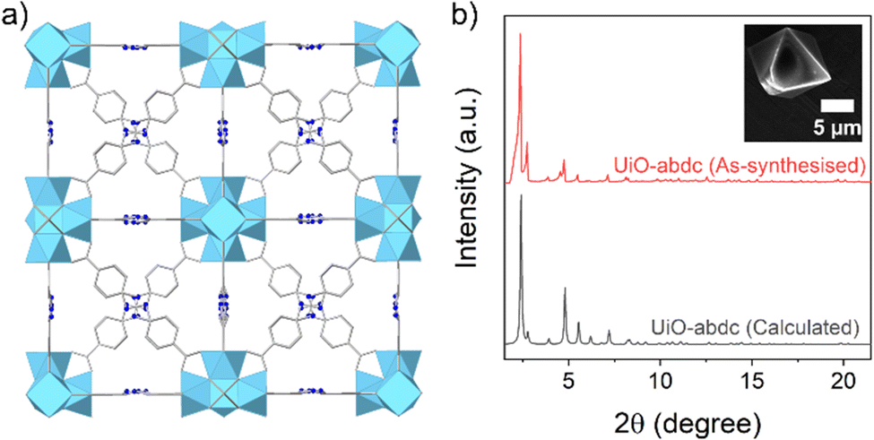 | ||
| Fig. 1 (a) Packing diagram for UiO-abdc (Refcode for the crystal structure: MAFWEY.24 H-atoms are omitted for clarity. Colour codes: C, grey; O, grey; N, bright blue; Zr, sky blue). (b) PXRD pattern (Mo Kα1) for the as-synthesised phase (red), compared to the calculated profile (grey) and (inset) SEM image of a single particle of UiO-abdc. | ||
UiO-abdc was prepared using a previously reported method.25 The agreement of the PXRD (powder X-ray diffraction) pattern with the calculated profile validated the formation of the target material (Fig. 1b). The FT-IR (Fourier transform infrared) spectrum for UiO-abdc comprised of signals present in the linker (Fig. S1, ESI†). SEM (scanning electron microscopy) images exhibited the formation of micron-sized particles with the typical octahedron morphology (Fig. 1b inset, S2). The TGA (thermogravimetric analysis) profile followed the previously observed25 thermal stability (∼450 °C) for this compound (Fig. S3, ESI†). Low temperature N2 adsorption (77 K) also validated the successful synthesis with a calculated BET area of 2838 m2 g−1 (Fig. S4, ESI†), that corroborated well with the previous report.25 The pristine MOF was found to have Raman-active vibrational modes (Fig. 3a). Solid-state NMR – proton 1H and carbon 13C, further validated the formation of the target material, with the presence of anticipated signals corresponding to the organic linker (Fig. S13 and S14, ESI†). The pair of relatively narrow peaks at ∼7.8 ppm in the 1H spectrum for the pristine powder correspond to the protons attached to the aromatic rings. The region 0–4 ppm contained a collection of peaks at ∼0.4 ppm and a peak at 3.3 ppm. Protons of Zr–OH groups have been assigned for similar MOFs to the region 0–3 ppm.27,28 The 13C spectrum for the pristine powder contained five main peaks, as expected for the number of chemically distinct sites in the linker. There is some broadening at the base of the narrow peaks. This could be due to disorder/motion of the linker, or free linker. The 5 peaks have isotropic chemical shifts δiso of 171.6, 154.9, 135.8, 129.8, and 121.2 ppm, which can be assigned to COO−, CN, C(COO), CH, and CH, respectively.
To test the electrochemical behaviour of UiO-abdc, electrodes were prepared by grinding MOF powders with conductive carbon (Super C65) and using a water-soluble binder, carboxymethyl cellulose (CMC), in a ratio of 6![[thin space (1/6-em)]](https://www.rsc.org/images/entities/char_2009.gif) :3:1 respectively. SEM images of this phase showed the presence of well distributed MOF crystallites anchored within the carbon matrix (Fig. S5, ESI†). The Raman spectrum also validated the retention of signals from the MOF upon preparation of electrode (Fig. 3a). Likewise, both 1H and 13C NMR spectra showed presence of all the signals from the pristine solid in the electrode phase (Fig. S13 and S14, ESI†).
:3:1 respectively. SEM images of this phase showed the presence of well distributed MOF crystallites anchored within the carbon matrix (Fig. S5, ESI†). The Raman spectrum also validated the retention of signals from the MOF upon preparation of electrode (Fig. 3a). Likewise, both 1H and 13C NMR spectra showed presence of all the signals from the pristine solid in the electrode phase (Fig. S13 and S14, ESI†).
Initially, galvanostatic charge–discharge cycling was carried out at a current density of 10 mA g−1. A capacity of 180 mA h g−1 was observed in the first discharge (Fig. S6, ESI†). A significant irreversible capacity was noticed for the first cycle (Fig. S6, ESI†), which could be ascribed to the formation of solid–electrolyte interface (SEI) layer and irreversible insertion of Na-ions in the carbon.29 Thereafter, a stable discharge capacity of ∼100 mA h g−1 was observed over 150 cycles, with high Coulombic efficiencies (Fig. S7, ESI†). The voltage curves comprised of a short plateau between 1.2 to 1.7 V (Fig. S6, ESI†), and the differential capacity plot for the initial cycles further confirmed the participation of the azo-group17 for charge storage with a prominent redox couple (Fig. 2a and Fig. S8, ESI†). The remaining voltage trace had a sloping profile with another plateau at lower potential (Fig. S6 and S8, ESI†). This indicates the participation of the porosity from the MOF for inserting excess ions as well as contribution from the conductive additive. It has previously been observed that UiO-based MOFs with no redox-active nodes are able to reversibly insert alkali metal ions to a limited extent.30–32 Also, based on the cell prepared using only the conductive carbon and binder (Fig. S9, ESI†), partial contribution from the additive could be ascribed towards the total capacity.
 | ||
| Fig. 2 (a) Zoomed plot of differential capacity for UiO-abdc in 3rd cycle obtained at a current rate of 10 mA g−1. (b) Rate performance for UiO-abdc, cycled 5 times at each different current rate. | ||
To examine the electrochemical behaviour further, the electrodes were also cycled at 25 mA g−1. The second cycle discharge capacity was ∼88 mA h g−1 which remained stable over 150 cycles, with stable Coulombic efficiencies (Fig. S10, ESI†). The rate performance was tested by cycling the cell from 10 mA g−1 up to 1 A g−1 (Fig. 2b). It is worth noting that all the initial capacity was fully recovered when the current was reduced back to 10 mA g−1 after cycling at a very high current density (1 A g−1). Although there is scope to improve the achievable specific capacities, relative to benchmark solids, the cycling stability and smooth rate capability further endorses the potential of functional pristine MOFs.
Subsequently, the MOF was characterised post-cycling by multiple techniques. The ex situ PXRD patterns after the first discharge and first charge validated the retention of the framework and absence of any crystalline decomposition products (Fig. S11, ESI†). The SEM images after 1 cycle showed retention of octahedron shaped crystallites. After 5 cycles, the PXRD pattern further reinforced the structural integrity, which was also supported by the SEM images of the corresponding phase. To further probe the material after cycling, ex situ Raman spectroscopy was employed. Although the strong stretching peak for the N![[double bond, length as m-dash]](https://www.rsc.org/images/entities/char_e001.gif) N bond17 is masked, a discernible decrease in the intensity for peaks at 927 cm−1 and 1182 cm−1 was observed upon first sodiation (Fig. 3a). Interestingly, after charging up to 2.5 V, the peaks fully reappeared suggesting complete reversibility of Na-ion insertion within the material. The other peaks present in the pristine material were found to be relatively unchanged at both the steps. To better understand the changing vibrational modes, a test molecule resembling the linker in UiO-abdc was optimised using DFT and a simulated Raman spectrum was generated for it (Fig. S12, ESI†).
N bond17 is masked, a discernible decrease in the intensity for peaks at 927 cm−1 and 1182 cm−1 was observed upon first sodiation (Fig. 3a). Interestingly, after charging up to 2.5 V, the peaks fully reappeared suggesting complete reversibility of Na-ion insertion within the material. The other peaks present in the pristine material were found to be relatively unchanged at both the steps. To better understand the changing vibrational modes, a test molecule resembling the linker in UiO-abdc was optimised using DFT and a simulated Raman spectrum was generated for it (Fig. S12, ESI†).
 | ||
| Fig. 3 (a) Raman spectra for UiO-abdc, dried electrode before cycling, after 1st discharge (0.01 V) and after 1st charge (2.5 V) [laser source – 532 nm]. (b) 23Na MAS NMR spectra (12.5 kHz MAS, 9.4 T). From bottom to top: electrode after 1st discharge, electrode after 1st charge, MOF soaked in electrolyte then washed, blank (no MOF) after 1st discharge. | ||
The two peaks at 914 cm−1 and 1178 cm−1 in the simulated pattern mainly relate to the vibrations involving the C–C bonds in the phenyl rings, which consequently cause the motions for the C–N bond. In the predicted pattern for the sodiated form of this molecule, the above peaks of interest reduce in intensity. The decrease in intensities can be correlated to the corresponding changes in the profile for UiO-abdc upon sodiation, that are linked to the locked motion of the azo group.
Solid-state NMR spectroscopy was also performed for samples post-cycling. The 1H spectra broadened after cycling, indicating variation in the local environment (Fig. S13, ESI†). This could arise from disorder of the linker, due to the presence of sodium and its effect on the structure, or the presence of paramagnetic radical groups in the structure which have previously been observed during lithiation of organic anodes.33 Additional peaks in the region 0–4 ppm are likely to be from residual electrolyte/SEI. As for the 1H spectra, the peaks in 13C spectra broadened indicating variation in the local environment (Fig. S14, ESI†). The 23Na MAS NMR spectra for the cycled electrodes showed two overlapping peaks and were similar for the two states of charge (Fig. 3b).
The 1st discharge spectrum with proton decoupling had some differences to that, with a small additional feature, indicating an additional sodium environment, that is more associated with protons, of those in the MOF framework. 23Na spectra were also recorded for the 1st discharge of a cell without the MOF and a MOF sample soaked in the electrolyte and washed. These showed that some Na is retained from residual electrolyte, although much lower signal intensity than for the other samples, and peak maximum moved to lower chemical shift. This suggests that some of the 23Na signal observed in the spectra for the MOF electrode powders relates to sodium inserted (or adsorbed) into the conductive carbon, or SEI/electrolyte, which is irreversible or present upon cycling regardless of state of charge.
In summary, the potential of pristine MOFs having only an azo-functionalised organic ligand, as electrode materials is demonstrated in a Zr(IV)-based MOF – UiO-abdc. The electrode delivered a stable moderate capacity of ∼100 mA h g−1 over 150 cycles at a low current rate. Detailed characterisation using ex situ Raman and solid-state NMR spectroscopy further reinforced the participation of the azo group and pores in the MOF for charge storage. We believe that these findings will enable further exploration of the rich library of MOFs as battery electrode materials and propel research on functional porous organic solids.
This work was supported by Faraday Institution (Grant – FIRG018). We are grateful to Engineering and Physical Sciences Research Council (EPSRC) for the Light Element Facility Grant (EP/T019298/1) and Strategic Equipment Resource Grant (EP/R023751/1). The authors thank Dr Gavin Peters (University of St. Andrews) for his assistance with TGA measurement.
Conflicts of interest
There are no conflicts to declare.Notes and references
- T. M. Gür, Energy Environ. Sci., 2018, 11, 2696–2767 RSC.
- J. Y. Hwang, S. T. Myung and Y. K. Sun, Chem. Soc. Rev., 2017, 46, 3529–3614 RSC.
- N. Tapia-Ruiz, A. R. Armstrong, H. Alptekin, M. A. Amores, H. Au, J. Barker, R. Boston, W. R. Brant, J. M. Brittain, Y. Chen, M. Chhowalla, Y.-S. Choi, S. I. R. Costa, M. Crespo Ribadeneyra, S. A. Cussen, E. J. Cussen, W. I. F. David, A. V. Desai, S. A. M. Dickson, E. I. Eweka, J. D. Forero-Saboya, C. P. Grey, J. M. Griffin, P. Gross, X. Hua, J. T. S. Irvine, P. Johansson, M. O. Jones, M. Karlsmo, E. Kendrick, E. Kim, O. V. Kolosov, Z. Li, S. F. L. Mertens, R. Mogensen, L. Monconduit, R. E. Morris, A. J. Naylor, S. Nikman, C. A. O’Keefe, D. M. C. Ould, R. G. Palgrave, P. Poizot, A. Ponrouch, S. Renault, E. M. Reynolds, A. Rudola, R. Sayers, D. O. Scanlon, S. Sen, V. R. Seymour, B. Silván, M. T. Sougrati, L. Stievano, G. S. Stone, C. I. Thomas, M.-M. Titirici, J. Tong, T. J. Wood, D. S. Wright and R. Younesi, J. Phys. Energy, 2021, 3, 031503 CrossRef CAS.
- P. K. Nayak, L. Yang, W. Brehm and P. Adelhelm, Angew. Chem., Int. Ed., 2018, 57, 102–120 CrossRef CAS PubMed.
- Y. Li, Y. Lu, P. Adelhelm, M. M. Titirici and Y. S. Hu, Chem. Soc. Rev., 2019, 48, 4655–4687 RSC.
- W. Zhang, F. Zhang, F. Ming and H. N. Alshareef, EnergyChem, 2019, 1, 100012 CrossRef.
- J. J. Shea and C. Luo, ACS Appl. Mater. Interfaces, 2020, 12, 5361–5380 CrossRef CAS PubMed.
- P. Poizot, J. Gaubicher, S. Renault, L. Dubois, Y. Liang and Y. Yao, Chem. Rev., 2020, 120, 6490–6557 CrossRef CAS PubMed.
- D. N. Rainer, A. V. Desai, A. R. Armstrong and R. E. Morris, J. Mater. Chem. A, 2021, 9, 27361–27369 RSC.
- Y. Lu, Q. Zhang, L. Li, Z. Niu and J. Chen, Chem, 2018, 4, 2786–2813 CAS.
- A. E. Baumann, D. A. Burns, B. Liu and V. S. Thoi, Commun. Chem., 2019, 2, 86 CrossRef.
- C. Li, L. Liu, J. Kang, Y. Xiao, Y. Feng, F.-F. Cao and H. Zhang, Energy Storage Mater., 2020, 31, 115–134 CrossRef.
- E. Wang, M. Chen, X. Guo, S.-L. Chou, B. Zhong and S.-X. Dou, Small Methods, 2020, 4, 1900163 CrossRef CAS.
- W. H. Bin and L. X. W. (David), Sci. Adv., 2017, 3, eaap9252 CrossRef PubMed.
- R. Zhao, Z. Liang, R. Zou and Q. Xu, Joule, 2018, 2, 2235–2259 CrossRef CAS.
- Z. Liu, F. Zheng, W. Xiong, X. Li, A. Yuan and H. Pang, SmartMat, 2021, 2, 488–518 CrossRef CAS.
- C. Luo, G.-L. Xu, X. Ji, S. Hou, L. Chen, F. Wang, J. Jiang, Z. Chen, Y. Ren, K. Amine and C. Wang, Angew. Chem., Int. Ed., 2018, 57, 2879–2883 CrossRef CAS PubMed.
- C. Luo, O. Borodin, X. Ji, S. Hou, K. J. Gaskell, X. Fan, J. Chen, T. Deng, R. Wang, J. Jiang and C. Wang, Proc. Natl. Acad. Sci. U. S. A., 2018, 115, 2004–2009 CrossRef CAS PubMed.
- G. Zhao, Y. Zhang, Z. Gao, H. Li, S. Liu, S. Cai, X. Yang, H. Guo and X. Sun, ACS Energy Lett., 2020, 5, 1022–1031 CrossRef CAS.
- M. K. Shehab, K. S. Weeraratne, T. Huang, K. U. Lao and H. M. El-Kaderi, ACS Appl. Mater. Interfaces, 2021, 13, 15083–15091 CrossRef CAS PubMed.
- T. Shimizu, T. Mameuda, H. Toshima, R. Akiyoshi, Y. Kamakura, K. Wakamatsu, D. Tanaka and H. Yoshikawa, ACS Appl. Energy Mater., 2022, 5, 5191–5198 CrossRef CAS.
- T. Shimizu, N. Tanifuji and H. Yoshikawa, Angew. Chem., Int. Ed., 2022, 61, e202206093 CAS.
- L. T. M. Hoang, L. H. Ngo, H. L. Nguyen, H. T. H. Nguyen, C. K. Nguyen, B. T. Nguyen, Q. T. Ton, H. K. D. Nguyen, K. E. Cordova and T. Truong, Chem. Commun., 2015, 51, 17132–17135 RSC.
- C. L. Hobday, R. J. Marshall, C. F. Murphie, J. Sotelo, T. Richards, D. R. Allan, T. Düren, F.-X. Coudert, R. S. Forgan, C. A. Morrison, S. A. Moggach and T. D. Bennett, Angew. Chem., Int. Ed., 2016, 55, 2401–2405 CrossRef CAS PubMed.
- R. J. Marshall, C. L. Hobday, C. F. Murphie, S. L. Griffin, C. A. Morrison, S. A. Moggach and R. S. Forgan, J. Mater. Chem. A, 2016, 4, 6955–6963 RSC.
- H. D. Cornell, Y. Zhu, S. Ilic, N. E. Lidman, X. Yang, J. B. Matson and A. J. Morris, Chem. Commun., 2022, 58, 5225–5228 RSC.
- S. Devautour-Vinot, G. Maurin, C. Serre, P. Horcajada, D. Paula da Cunha, V. Guillerm, E. de Souza Costa, F. Taulelle and C. Martineau, Chem. Mater., 2012, 24, 2168–2177 CrossRef CAS.
- M. C. Lawrence, C. Schneider and M. J. Katz, Chem. Commun., 2016, 52, 4971–4974 RSC.
- C. Bommier and X. Ji, Small, 2018, 14, 1703576 CrossRef PubMed.
- B. Tang, S. Huang, Y. Fang, J. Hu, C. Malonzo, D. G. Truhlar and A. Stein, J. Chem. Phys., 2016, 144, 194702 CrossRef PubMed.
- R. Malik, M. J. Loveridge, L. J. Williams, Q. Huang, G. West, P. R. Shearing, R. Bhagat and R. I. Walton, Chem. Mater., 2019, 31, 4156–4165 CrossRef CAS.
- A. Tang, X. He, H. Yin, Y. Li, Y. Zhang, S. Huang and D. G. Truhlar, J. Phys. Chem. C, 2021, 125, 9679–9687 CrossRef CAS.
- M. Armand, S. Grugeon, H. Vezin, S. Laruelle, P. Ribière, P. Poizot and J.-M. Tarascon, Nat. Mater., 2009, 8, 120–125 CrossRef CAS PubMed.
Footnote |
| † Electronic supplementary information (ESI) available: Experimental details, material characterisation, electrochemical studies. See DOI: https://doi.org/10.1039/d2cc06154f. The research data underpinning this publication can be accessed at https://doi.org/10.17630/e06b0d3a-6dc5-4ea6-b865-0324094d2edd |
| This journal is © The Royal Society of Chemistry 2023 |